

Page 1

Service Guide
3DUW1XPEHU(
$SULO
)RU:DUUDQW\LQIRUPDWLRQUHIHUWRWKHEDFNRIWKHPDQXDO
&RS\ULJKW$JLOHQW7HFKQRORJLHV,QF
$OO5LJKWV5HVHUYHG
$JLOHQW($DQG($
'&3RZHU6XSSOLHV
Page 2

The Agilent E3633A and Agilent E3634A are high performance 200 watt singleoutput dual range programmable DC power supplies with both GPIB and RS232 interfaces. The combination of bench-top and system features in these
power supplies provides versatile solutions for your design and test
requirements.
Convenient bench-top features
• Single-output dual range
• Easy-to-use knob control settings
• Highly visible vacuum-fluorescent display meters
• High accuracy and high resolution
• Remote voltage sensing
• Overvoltage and overcurrent protection
• Output on/off
• Excellent load and line regulation and low ripple and noise
• Operating states storage
• Portable, ruggedized case with non-skid feet
• Front and Rear output terminals
• Retrieving/Scrolling error messages on the display
Flexible system features
• GPIB (IEEE-488) and RS-232 interfaces are standard
• SCPI (Standard Commands for Programmable Instruments) compatibility
• I/O setup easily done from front-panel
• Software calibration, no internal adjustments required
Agilent E3633A and E3634A
DC Power Supplies
Page 3

The Front Panel at a Glance
1 8V/20A range selection key (E3633A)
25V/7A range selection key (E3634A)
2 20V/10A range selection key (E3633A)
50V/4A range selection key (E3634A)
3 Overvoltage protection key
4 Overcurrent protection key
5 Display limit key
6 Recall operating state key
2
7 Store operating state/Local key
8 Error/Calibrate key
9 I/O Configuration/Secure key
10 Output On/Off key
11 Control knob
12 Resolution selection keys
13 Voltage/current adjust selection key
Page 4

1 8V/20A* or 25V/7A** range selection key Selects the 8V/20A or 25V/7A
range and allows the full rated output to 8V/20A or 25V/7A.
2 20V/10A* or 50V/4A** range selection key Selects the 20V/10A or
50V/4A range and allows the full rated output to 20V/10A or 50V/4A.
3 Overvoltage protection key Enables or disables the overvoltage protection
function, sets trip voltage level, and clears the overvoltage condition.
4 Overcurrent protection key Enables or disables the overcurrent protection
function, sets trip current level, and clears the overcurrent condition.
5 Display limit key Shows voltage and current limit values on the display and
allows knob adjustment for setting limit values.
6 Recall operating state key Recalls a previously stored operating state from
location ‘‘1’’, ‘‘2’’, or ‘‘3’’.
7 Store operating state / Local key
1
Stores an operating state in location ‘‘1’’,
‘‘2’’, or ‘‘3’’ / or returns the power supply to local mode from remote interface
mode.
8 E r ror / Cal ibrate k e y
2
Displays error codes generated during operation, selftest and calibration / or enables calibration mode (the power supply must be
unsecured before performing calibration). See Service Guide for more details
on calibration.
9 I/O Configuration / Secure key
3
Configures the power supply for remote
interfaces / or secure or unsecure the power supply for calibration. See
Service Guide for more details on how to secure or unsecure the power supply.
10 Output On/Off key Enables or disables the power supply output. This key
toggles between on and off.
11 Control knob Increases or decreases the value of the blinking digit by turning
clockwise or counter clockwise.
12 Resolution selection keys Move the blinking digit to the right or left.
13 Voltage/current adjust selection key Selects the knob control function for
voltage or current adjustment.
1
The key can be used as the ‘‘Local’’ key when the power supply is in the remote
interface mode.
2
You can enable the ‘‘calibration mode’’ by holding down this key when you
turn on the power supply.
3
You can use it as the ‘‘Secure’’ or ‘‘Unsecure’’ key when the power supply is
in the calibration mode.
*For Agilent E3633A Model **For Agilent E3634A Model
3
Page 5
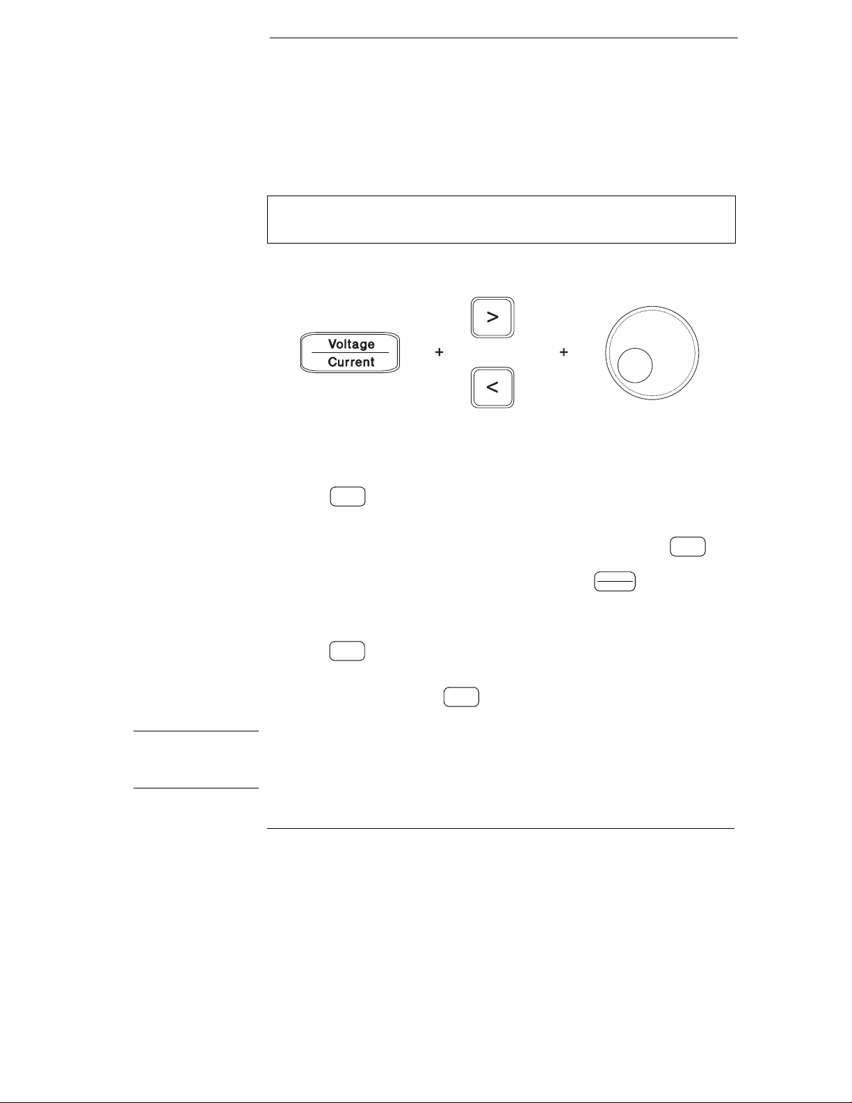
Front-Panel Voltage and Current Limit Settings
You can set the voltage and current limit values from the front panel using the
following method.
Use the voltage/current adjust selection key, the resolution selection keys,
and the control knob to change the voltage and current limit values.
1 Select the desired range using the range selection keys after turning on the
power supply.
2 Press the
3 Move the blinking digit to the appropriate position using the resolution
selection keys and change the blinking digit value to the desired voltage limit
by turning the control knob. If the display limit times out, press the key
again.
4 Set the knob to current control mode by pressing the key.
5 Move the blinking digit to the appropriate position using the resolution
selection keys and change the blinking digit value to the desired current limit
by turning the control knob.
6 Press the
will go to output monitoring mode automatically to display the voltage and
current at the output or the display will go to output monitoring mode
immediately by pressing the
Display
key to show the limit values on the display.
Limit
Volt ag e
Current
Output
key to enable the output. After about 5 seconds, the display
On/Off
Output
key again.
On/Off
Display
Limit
Note All front panel keys and controls can be disabled with remote interface commands.
The Agilent E3633A and Agilent E3634A must be in "Local" mode for the front panel
keys and controls to function.
4
Page 6
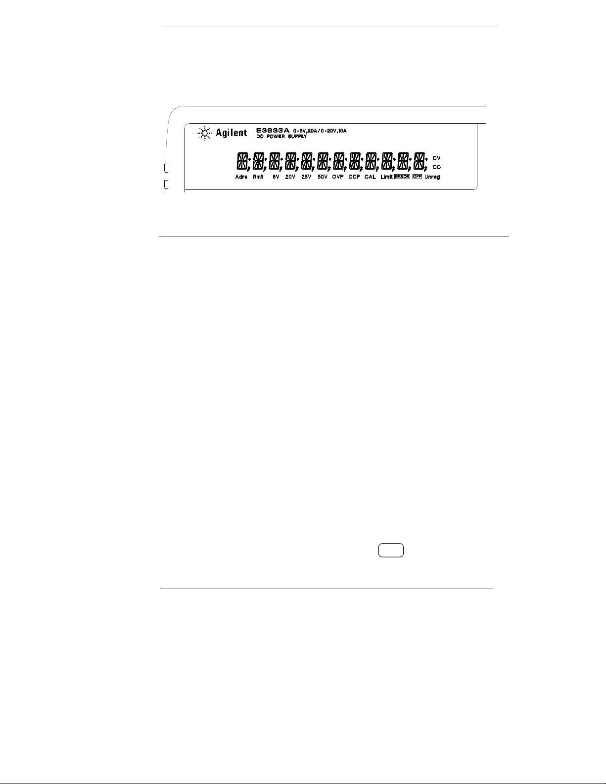
Display Annunciators
Adrs Power supply is addressed to listen or talk over a remote interface.
Rmt Power supply is in remote interface mode.
8V Shows the 8V/20A range is selected. (Agilent E3633A model)
20V Shows the 20V/10A range is selected. (Agilent E3633A model)
25V Shows the 25V/7A range is selected. (Agilent E3634A model)
50V Shows the 50V/4A range is selected. (Agilent E3634A model)
OVP The overvoltage protection function is enabled when the
annunciator turns on or the overvoltage protection circuit has
caused the power supply to shutdown when the annunciator blinks.
OCP The overcurrent protection function is enabled when the
annunciator turns on or the overcurrent protection circuit has
caused the power supply to shutdown when the annunciator blinks.
CAL The power supply is in calibration mode.
Limit The display shows the limit values of voltage and current.
ERROR Hardware or remote interface command errors are detected and
the error bit has not been cleared.
OFF The output of the power supply is disabled (For more information,
see page 52 in the User’s Guide).
Unreg The output of the power supply is unregulated (output is neither CV
nor CC).
CV The power supply is in constant voltage mode.
CC The power supply is in constant current mode.
To review the display annunciators, hold down key as you turn on
Display
Limit
the power supply.
5
Page 7

The Rear Panel at a Glance
1 Power-line voltage setting
2 Power-line fuse-holder assembly
3 AC inlet
5 GPIB (IEEE-488) interface connector
6 RS-232 interface connector
7 Rear output terminals
4 Power-line module
Use the front-panel key to:
I/O
Config
• Select the GPIB or RS-232 interface (see chapter 3 in User’s Guide).
• Set the GPIB bus address (see chapter 3 in User’s Guide).
• Set the RS-232 baud rate and parity (see chapter 3 in User’s Guide).
6
Page 8

In This Book
This is the Service Guide for your Agilent E3633A and E3634A DC power
supplies. Unless otherwise stated, the information in this manual applies to
both two models.
Specifications Chapter 1 lists the power supply’s specifications and
describes how to interpret these specifications.
Quick Start Chapter 2 prepares the power supply for use and helps you get
familiar with the front panel features.
Calibration Procedures Chapter 3 provides performance verification and
calibration procedures.
Theory of Operation Chapter 4 describes block and circuit level theory
related to the operation of the power supply.
Service Chapter 5 provides guidelines for returning your power supply to
Agilent Technologies for servicing, or for servicing it yourself.
Replaceable Parts Chapter 6 contains a detailed parts list of the power
supply.
Backdating Chapter 7 describes the difference between this manual and
older issues of this manual.
Schematics Chapter 8 co ntains th e po wer sup ply ’s sch ematic s, disasse mbly
drawings, and component locator drawings.
If you have questions relating to the operation of the power supply, call
1-800-452-4844 in the United States, or contact your nearest Agilent
Technologies Sales Office.
If your Agilent E3633A or Agilent E3634A fails within three years of purchase,
Agilent will repair or replace it free of charge. Call 1-800-258-5165 ("Express
Exchange") in the United States, or contact your nearest Agilent Technologies
Sales Office.
7
Page 9

8
Page 10

Contents
Chapter 1 Specifications
Performance Specifications - - - - - - - - - - - - - - - - - - - - - - - - - - - - - 11
Supplemental Characteristics - - - - - - - - - - - - - - - - - - - - - - - - - - - 13
Chapter 2 Quick Start
To Prepare the Power Supply for Use - - - - - - - - - - - - - - - - - - - - - 23
To Check the Rated Voltages of the Power Supply - - - - - - - - - - - 25
To Check the Rated Currents of the Power Supply - - - - - - - - - - 26
To Use the Power Supply in Constant Voltage Mode - - - - - - - - - 28
To Use the Power Supply in Constant Current Mode - - - - - - - - - 30
To Store and Recall the Instrument State - - - - - - - - - - - - - - - - - - 32
To Program Overvoltage Protection - - - - - - - - - - - - - - - - - - - - - - 34
Setting the OVP Level and Enable the OVP Circuit - - - - - - - - 34
Checking OVP Operation - - - - - - - - - - - - - - - - - - - - - - - - - - - - 35
Clearing the Overvoltage Condition - - - - - - - - - - - - - - - - - - - - 35
To Program Overcurrent Protection - - - - - - - - - - - - - - - - - - - - - - 37
Setting the OCP Level and Enable the OCP Circuit - - - - - - - - 37
Checking OCP Operation - - - - - - - - - - - - - - - - - - - - - - - - - - - - 38
Clearing the Overcurrent Condition - - - - - - - - - - - - - - - - - - - - 38
To Rack Mount the Power Supply - - - - - - - - - - - - - - - - - - - - - - - - 40
Contents
Chapter 3 Calibration Procedures
Agilent Technologies Calibration Services - - - - - - - - - - - - - - - - - 45
Calibration Interval - - - - - - - - - - - - - - - - - - - - - - - - - - - - - - - - - - - - 45
Automating Calibration Procedures - - - - - - - - - - - - - - - - - - - - - - 46
Test Considerations - - - - - - - - - - - - - - - - - - - - - - - - - - - - - - - - - - - 46
Recommended Test Equipment - - - - - - - - - - - - - - - - - - - - - - - - - - 47
Performance Verification Tests - - - - - - - - - - - - - - - - - - - - - - - - - - 48
Self-Test - - - - - - - - - - - - - - - - - - - - - - - - - - - - - - - - - - - - - - - - - - 48
Performance Verification Tests - - - - - - - - - - - - - - - - - - - - - - - 48
Measurement Techniques- - - - - - - - - - - - - - - - - - - - - - - - - - - - - - - 49
Setup for Most Tests - - - - - - - - - - - - - - - - - - - - - - - - - - - - - - - - 49
Electronic Load - - - - - - - - - - - - - - - - - - - - - - - - - - - - - - - - - - - - 49
General Measurement Techniques - - - - - - - - - - - - - - - - - - - - - 50
Current-Monitoring Resistor- - - - - - - - - - - - - - - - - - - - - - - - - - 50
Programming - - - - - - - - - - - - - - - - - - - - - - - - - - - - - - - - - - - - - - 50
9
Page 11

Contents
Contents
Chapter 3 Calibration Procedures (Continued)
Constant Voltage (CV) Verifications- - - - - - - - - - - - - - - - - - - - - - - 51
Constant Voltage Test Setup - - - - - - - - - - - - - - - - - - - - - - - - - - 51
Voltage Programming and Readback Accuracy - - - - - - - - - - - 51
CV Load Effect (Load Regulation) - - - - - - - - - - - - - - - - - - - - - 52
CV Source effect (Line Regulation)- - - - - - - - - - - - - - - - - - - - - 53
CV PARD (Ripple and Noise) - - - - - - - - - - - - - - - - - - - - - - - - - 54
Load Transient Response Time - - - - - - - - - - - - - - - - - - - - - - - - 55
Constant Current (CC) Verifications - - - - - - - - - - - - - - - - - - - - - - 56
Constant Current Test Setup - - - - - - - - - - - - - - - - - - - - - - - - - - 56
Current Programming and Readback Accuracy - - - - - - - - - - - 56
CC Load Effect (Load Regulation) - - - - - - - - - - - - - - - - - - - - - 57
CC Source Effect (Line Regulation) - - - - - - - - - - - - - - - - - - - - 58
CC PARD (Ripple and Noise) - - - - - - - - - - - - - - - - - - - - - - - - - 58
Common Mode Current Noise - - - - - - - - - - - - - - - - - - - - - - - - - - - 59
Performance Test Record for Agilent E3633A and E3634A - - - - 60
CV Performance Test Record - - - - - - - - - - - - - - - - - - - - - - - - - 60
CC Performance Test Record - - - - - - - - - - - - - - - - - - - - - - - - - 60
Calibration Security Code - - - - - - - - - - - - - - - - - - - - - - - - - - - - - - - 61
To Unsecure the Power Supply for Calibration - - - - - - - - - - - 62
To Unsecure the Power Supply Without the Security Code - 63
Calibration Count - - - - - - - - - - - - - - - - - - - - - - - - - - - - - - - - - - - - - 64
Calibration Message - - - - - - - - - - - - - - - - - - - - - - - - - - - - - - - - - - - 64
General Calibration/Adjustment Procedure - - - - - - - - - - - - - - - - - 65
Front Panel Voltage and Current Calibration - - - - - - - - - - - - - 66
Aborting a Calibration in Progress - - - - - - - - - - - - - - - - - - - - - - - - 71
Calibration Record for Agilent E3633A/E3634A - - - - - - - - - - - - - 72
Error Messages - - - - - - - - - - - - - - - - - - - - - - - - - - - - - - - - - - - - - - - 73
An Example program of Excel 97 for Calibration - - - - - - - - - - - - 75
Chapter 4 Theory of Operation
10
Block Diagram Overview - - - - - - - - - - - - - - - - - - - - - - - - - - - - - - - 85
AC Input and Bias Supplies- - - - - - - - - - - - - - - - - - - - - - - - - - - - - - 87
Floating Logic - - - - - - - - - - - - - - - - - - - - - - - - - - - - - - - - - - - - - - - - 88
D-to-A Converter - - - - - - - - - - - - - - - - - - - - - - - - - - - - - - - - - - - - - - 90
A-to-D Converter - - - - - - - - - - - - - - - - - - - - - - - - - - - - - - - - - - - - - - 91
Power Mesh and Control- - - - - - - - - - - - - - - - - - - - - - - - - - - - - - - - 92
Earth-Referenced Logic - - - - - - - - - - - - - - - - - - - - - - - - - - - - - - - - 94
Front Panel - - - - - - - - - - - - - - - - - - - - - - - - - - - - - - - - - - - - - - - - - - 94
Page 12

Contents
Chapter 5 Service
Operating Checklist - - - - - - - - - - - - - - - - - - - - - - - - - - - - - - - - - - - 97
Is the Power Supply Inoperative? - - - - - - - - - - - - - - - - - - - - - - 97
Does the Power Supply Fail Self-Test?- - - - - - - - - - - - - - - - - - 97
Types of Service Available - - - - - - - - - - - - - - - - - - - - - - - - - - - - - - 98
Standard Repair Service (worldwide) - - - - - - - - - - - - - - - - - - 98
Express Exchange (U.S.A. only)- - - - - - - - - - - - - - - - - - - - - - - 98
Repacking for Shipment - - - - - - - - - - - - - - - - - - - - - - - - - - - - - - - - 99
Electrostatic Discharge (ESD) Precautions - - - - - - - - - - - - - - - 100
Surface Mount Repair - - - - - - - - - - - - - - - - - - - - - - - - - - - - - - - - - 100
To Replace the Power-Line Fuse - - - - - - - - - - - - - - - - - - - - - - - - 100
To Disconnect the Output Using an External Relay - - - - - - - - - 101
Installation Procedure - - - - - - - - - - - - - - - - - - - - - - - - - - - - - - 101
Troubleshooting Hints - - - - - - - - - - - - - - - - - - - - - - - - - - - - - - - - 102
Unit is Inoperative - - - - - - - - - - - - - - - - - - - - - - - - - - - - - - - - - 102
Unit Reports Errors 740 to 750 - - - - - - - - - - - - - - - - - - - - - - - 102
Unit Fails Self-Test - - - - - - - - - - - - - - - - - - - - - - - - - - - - - - - - 102
Bias Supplies Problems - - - - - - - - - - - - - - - - - - - - - - - - - - - - - 103
Self-Test Procedures- - - - - - - - - - - - - - - - - - - - - - - - - - - - - - - - - - 104
Power-On Self-Test - - - - - - - - - - - - - - - - - - - - - - - - - - - - - - - - 104
Complete Self-Test - - - - - - - - - - - - - - - - - - - - - - - - - - - - - - - - 104
Contents
Chapter 6 Replaceable Parts
Replaceable Parts - - - - - - - - - - - - - - - - - - - - - - - - - - - - - - - - - - - - 108
To Order Replaceable Parts - - - - - - - - - - - - - - - - - - - - - - - - - 108
Backdating and Part Changes - - - - - - - - - - - - - - - - - - - - - - - - 108
E3633/E3634-60002 Main PC Assembly - - - - - - - - - - - - - - - - - - - 109
E3633-60003 Front-Panel Display PC Assembly - - - - - - - - - - - - 119
E3633-60011 Front Frame Assembly - - - - - - - - - - - - - - - - - - - - - 120
E3633A/E3634A Power Supply Assembly - - - - - - - - - - - - - - - - - 120
Manufacturer’s List - - - - - - - - - - - - - - - - - - - - - - - - - - - - - - - - - - - 121
Chapter 7 Backdating
Chapter 8 Schematics
11
Page 13

Contents
Contents
12
Page 14

1
Specifications
Page 15

Specifications
The performance specifications are listed in the following pages.
Specifications are warranted in the temperature range of 0 to 40°C with a
resistive load. Supplemental characteristics, which are not warranted but
are descriptions of performance determined either by design or testing.
Chapter 3 ‘‘Calibration Procedures’’ contains procedures for verifying the
performance specifications.
14
Page 16
Chapter 1 Specifications
Performance Specifications
Performance Specifications
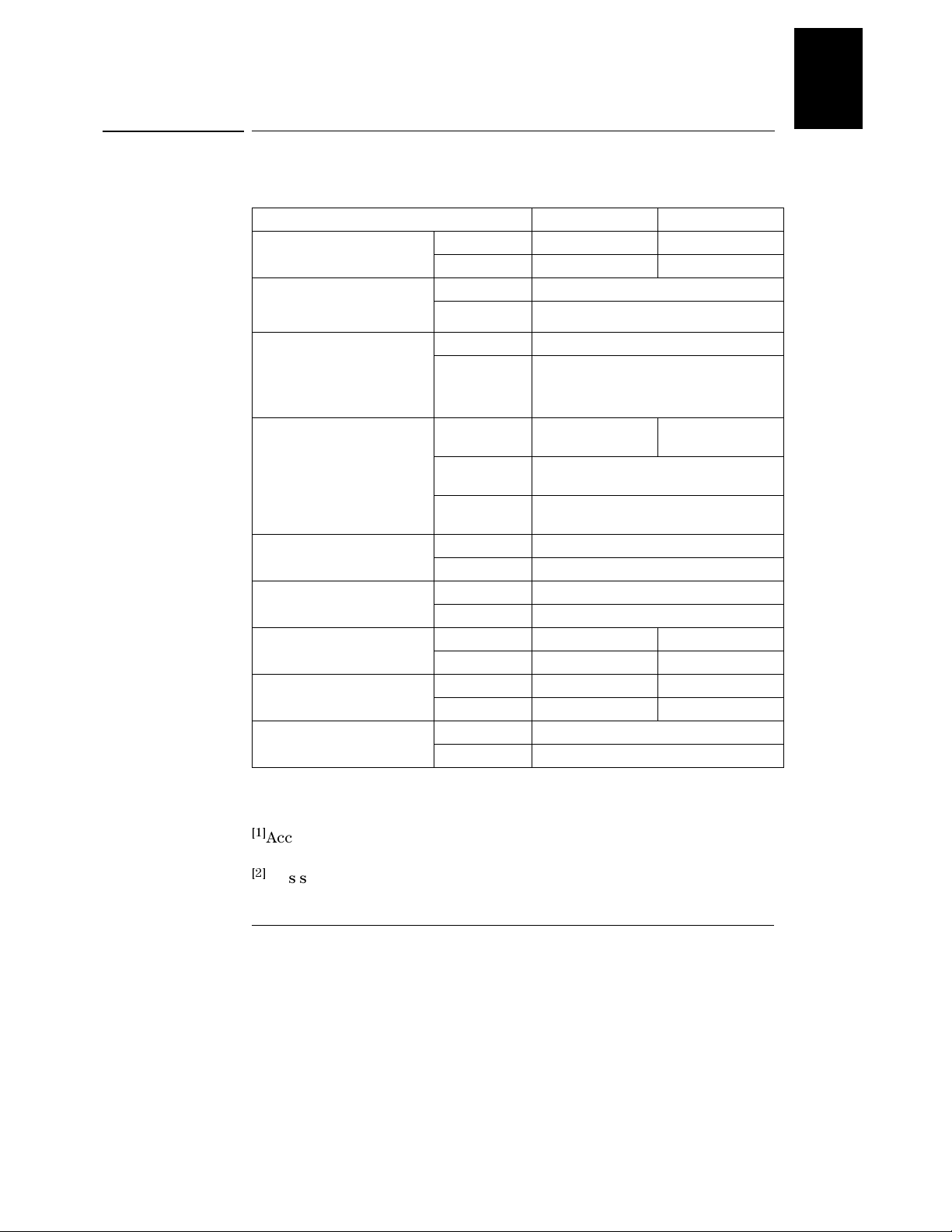
Table 1-1. Performance Specifications
Parameter Agilent E3633A Agilent E3634A
Output Ratings
(@ 0 °C - 40 °C)
Programming Accuracy
12 months (@ 25 °C ± 5 °C),
±(% of output + offset)
Readback A ccuracy
12 months (over GPIB and
RS-232 or front panel with
respect to actual output @ 25 °C
± 5 °C), ±(% of output + offset)
Ripple and Noise
(with outputs ung rounded, or
with either output terminal
grounded, 20 Hz to 20 MHz)
Load Regulation,
±(% of output + offset)
Line Regulation,
±(% of output + offset)
Programming Resolution Voltage 1 mV 3 mV
Readback Resolution Voltage 0.5 mV 1.5 mV
Front Panel Resolution Voltage 1 mV
[1] [2]
Low Range 0 to +8 V/0 to 20 A 0 to +25 V/0 to 7 A
High Range 0 to +20 V/0 to 10 A 0 to +50V/0 to 4 A
[1]
Voltage 0.05% + 10 mV
Current 0.2% + 10 mA
Voltage 0.05% + 5 mV
Current 0.15% + 5 mA
Normal mode
voltage
Normal mode
current
Common mode
current
Voltage <0.01% + 2 mV
Current <0.01% + 250 uA
Voltage <0.01% + 2 mV
Current <0.01% + 250 uA
Current 1 mA 0.5 mA
Current 1 mA 0.5 mA
Current 1 mA (< 10A), 10mA (
<0.35 mV rms and
3 mV p-p
<2 mA rms
<1.5 uA rms
<0.5 mV rms and
3 mV p-p
≥ 10A)
1
>@
$FFXUDF\VSHFLILFDWLRQVDUHDIWHUDQKRXUZDUPXSZLWKQRORDGDQG
FDOLEUDWLRQDW&
>@
7KLVVSHFLILFDWLRQPD\GHJUDGHZKHQWKHXQLWLVVXEMHFWHGWRDQ5)ILHOG
! 9PHWHU
15
Page 17

Chapter 1 Specifications
Performance Specifications
Transient Response Time
Less than 50 msec for output to recover to within 15 mV following a change in
output current from full load to half load or vice versa
Command Processing Time
Average time for output voltage to begin to change after receipt of digital data
when the power supply is connected directly to the GPIB or RS-232 is less than
100 msec
OVP and OCP Accuracy, ±(% of output + offset)
OVP 0.5% + 0.5 V
OCP 0.5% + 0.5 A
Activation time : Average time for output to start to drop after OVP or OCP
condition occurs.
OVP <1.5 msec when the trip voltage is equal or greater than 3 V
<10 msec when the trip voltage is less than 3 V
OCP <10 msec
16
Page 18
Chapter 1 Specifications
Supplemental Characteristics
Supplemental Characteristics
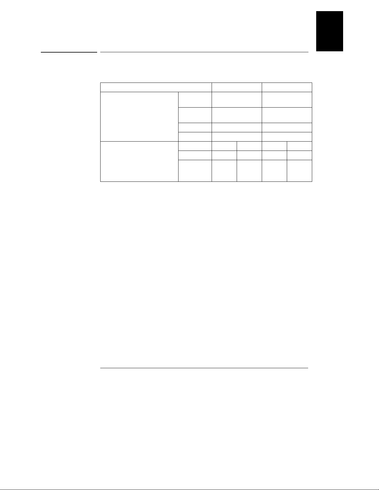
Table 1-2. Supplemental Characteristics
Parameter Agilent E3633A Agilent E3634A
Output Programming Range
(maximum programmable values)
Voltage Programming
Speed: Maximum time required
for output voltage to settle within
1% of its total excursion (for
resistive load). Excludes
command processing time.
Low Range 0 to +8.24 V/
0 to 20.6 A
High Range 0 to +20.6 V/
0 to 10.3 A
OVP 1 V to 22 V 1 V to 55 V
OCP 0 A to 22 A 0 A to 7.5 A
Full Load No Load Full Load No Load
Up 95 msec 45 msec 80 msec 100 msec
Down 30 msec 450 msec 30 msec 450 msec
0 to +25.75 V/
0 to 7.21 A
0 to +51.5V/
0 to 4.12 A
1
Remote Sensing Capability
Voltage drop Up to 0.7 V per each lead
Load regulation Add 5 mV to spec for each 1-volt change in the + output
lead due to load current changes.
Load voltage Subtract voltage drop in load leads from specified output
voltage rating.
Temperature Coefficient, ±(% of output + offset)
Maximum change in output/readback per °C after a 30-minute warm-up
Voltage 0.01% + 3 mV
Current 0.02% + 3 mA
Stability, ±(% of output + offset)
Following 1 hour warm-up, change in output over 8 hours under constant load,
line, and ambient temperature
Voltage 0.02% + 1 mV
Current 0.1% + 1 mA
17
Page 19

Chapter 1 Specifications
Supplemental Characteristics
Output Voltage Overshoot
During turn-on or turn-off of ac power, output plus overshoot will not exceed
1 V if the output control is set to less than 1 V. If the output control is set to
1 V or higher, there is no overshoot.
Programming Language
SCPI (Standard Commands for Programmable Instruments)
State Storage Memory
Three (3) user-configurable stored states
Recommended Calibration Interval
1 year
Output Terminal Isolation (maximum, from chassis ground)
±60 Vdc when connecting shorting conductors without insulation to the
(+) output to the (+) sense and the (-) output and the (-) sense terminals.
±240 Vdc when connecting insulated shorting conductors to the (+) output
to the (+) sense and the (-) output and the (-) sense terminals.
AC Input Ratings (selectable via rear panel selector)
std 115 Vac ± 10%, 47 to 63 Hz
opt 0E3 230 Vac ± 10%, 47 to 63 Hz
opt 0E9 100 Vac ± 10%, 47 to 63 Hz
Maximum Input Power
700 VA with full load
Cooling
Fan cooled
Operating Temperature
0 to 40 °C for full rated output. At higher temperatures, the output current is
derated linearly to 50% at 55 °C maximum temperature.
18
Page 20
Chapter 1 Specifications
Supplemental Characteristics
Storage Temperature
-20 to 70 °C for storage environment.
Environmental Conditions
Designed for indoor use in an installation category II, pollution degree 2
environment. Designed to operate at a maximum relative humidity of 95 %
and at altitudes of up to 2000 meters.
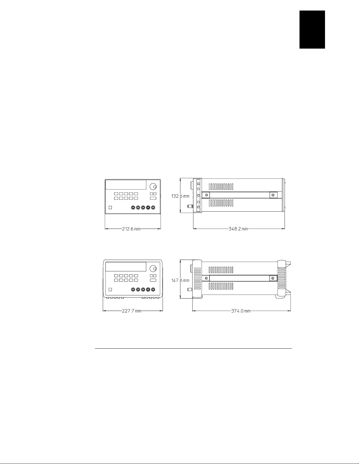
Dimensions*
213 mmW x 133 mmH x 348 mmD (8.4 x 5.2 x 13.7 in)
*See below for detailed information.
Weight
Net 9.5 kg (21 lb)
Shipping 12 kg (26 lb)
1
Figure 8-1. Dimensions of Agilent E3633A and E3634A Power Supplies
19
Page 21

Chapter 1 Specifications
Supplemental Characteristics
20
Page 22

2
Quick Start
Page 23

Quick Start
One of the first things you will want to do with your power supply is to become
acquainted with its front panel. Written procedures in this chapter prepare the
power supply for use and familiarize you with most front-panel operations.
• The power supply is shipped from the factory configured in the front-panel
operation mode. At power-on, the power supply is automatically set to
operate in the front-panel operation mode. When in this mode, the frontpanel keys can be used. When the power supply is in remote operation mode,
you can return to front-panel operation mode at any time by pressing the
Store
(Local) key if you did not previously send the front-panel lockout
Local
command. A change between front-panel and remote operation modes will
not result in a change in the output parameters.
• The power supply has two output ranges. This feature allows more voltage
at a lower current or more current at a lower voltage. The desired output
range is selected from the front panel or over the remote interfaces. The
20V for the E3633A and 25V or 50V for the E3634A annunciator indicates
or
the presently selected range.
• When you press key (the
Display
Limit
Limit annunciator flashes), the display of
the power supply goes to the limit mode and the present limit values will
be displayed. In this mode, you can also observe the change of the limit
values when adjusting the knob. If you press the key again or let the
Display
Limit
display time-out after several seconds, the power supply will return the
display to the meter mode (the
Limit annunciator turns off). In this mode,
the actual output voltage and current will be displayed.
• The output of the power supply can be enabled or disabled from the front
panel by pressing key. When the output is off, the
Output
On/Off
OFF annunciator
turns on and the output is disabled.
• The display provides the present operating status of the power supply with
annunciators and also informs the user of error codes. For example, the
power supply is operating in CV mode in the 8V/20A* or 25V/7A** range and
controlled from the front panel, then the
CV and 8V* or 25V** annunciators
will turn on. If, however, the power supply is remotely controlled, the
annunciator will also turn on, and when the power supply is being addressed
over GPIB interface, the
Adrs annunciator will turn on. See “Display
Annunciators’’ on page 5 for more information.
8V
Rmt
*For Agilent E3633A Model **For Agilent E3634A Model
22
Page 24

Chapter 2 Quick Start
To Prepare the Power Supply for Use
To Prepare the Power Supply for Use
The following steps help you verify that the power supply is ready for use.
Power
Output
On/Off
1 Check the list of supplied items.
Verify that you have received the following items with your power supply. If
anything is missing, contact your nearest Agilent Technologies Sales Office.
One power cord for your location.
One User’s Guide.
This Service Guide.
Certificate of Calibration.
2 Verify that the correct power-line voltage setting is selected and that
the correct power-line fuse is installed.
The line voltage is set to 100, 115 or 230 Vac from the factory according to the
input power option selected when you ordered the power supply. Change the
voltage setting if it is not correct for your location (see the next page for
detailed information). For 100 or 115 Vac operation, the correct fuse is 6.3 AT
(Agilent part number 2110-1030) and for 230 Vac operation, the correct fuse is
3.15 AT (Agilent part number 2110-1031).
3 Connect the power cord and turn on the power supply.
A power-on self-test occurs automatically when you turn on the power supply.
The front-panel display will light up while the power supply performs its
power-on self- test. After performing the self-test, the power supply will go into
the power-on / reset state; the output is disabled (the
on); the 8V/20A* or 25V/7A** range is selected (the
OFF annunciator turns
8V* or 25V** annunciator
turns on); the knob is selected for voltage control.
Notice that the
OVP and OCP annunciators also turn on.
4 Enable the outputs.
Output
Press key to enable the outputs. The
On/Off
8V* or 25**, OVP, OCP, and CV annunciators are lit. The flashing digit can be
OFF annunciator turns off and the
adjusted by turning the knob. Notice that the display is in the meter mode.
‘‘Meter mode’’ means that the display shows the actual output voltage and
current.
2
*For Agilent E3633A Model **For Agilent E3634A Model
23
Page 25

Chapter 2 Quick Start
To Prepare the Power Supply for Use
1
Remove the power cord. Remove the
fuse-holder assembly with a flat-blade
screwdriver from the rear panel.
2
Install the correct line fuse. Remove
the power-line voltage selector from the
power-line module.
100 or 115 Vac, 6.3 AT fuse
230 Vac, 3.15 AT fuse
3
Rotate the power-line voltage selector
until the correct voltage appears.
4
Replace the power-line voltage selector
and the fuse-holder assembly in the rear
panel.
100, 115, or 230 Vac
Install the correct fuse and verify that the correct line voltage appears in the
window.
24
Page 26

Power
Output
On/Off
Chapter 2 Quick Start
To Check the Rated Voltages of the Power Supply
To Check the Rated Voltages of the Power Supply
The following procedures check to ensure that the power supply produces its
rated voltage output with no load and properly responds to operation from the
front panel.
For each step, use the keys shown on the left margins.
1 Turn on the power supply.
The power supply will go into the power-on / reset state; the output is disabled
OFF annunciator turns on); the 8V/20A* or 25V/7A** range is selected (the
(the
8V* or 25V** annunciator turns on); and the knob is selected for voltage control.
2 Enable the outputs.
OFF annunciator turns off and the 8V* or 25V**, OVP, OCP, and CV
The
annunciators are lit. The flashing digit can be adjusted by turning the knob.
Notice that the display is in the meter mode. “Meter mode’’ means that the
display shows the actual output voltage and current.
2
3 Check that the front-panel voltmeter properly responds to knob
control.
Turn the knob clockwise or counter clockwise to check that the voltmeter
responds to knob control and the ammeter indicates nearly zero.
1
4 Ensure that the voltage can be adjusted from zero to the maximum
rated value.
Adjust the knob until the voltmeter indicates 0 volts and then adjust the knob
until the voltmeter indicates ‘‘8.0 volts’’* or ‘‘25.0 volts’’**.
1
You can use the resolution selection keys to move the flashing digit to the
right or left when setting the voltage.
*For Agilent E3633A Model **For Agilent E3634A Model
25
Page 27

Power
Output
On/Off
Display
Limit
Volt ag e
Current
Chapter 2 Quick Start
To Check the Rated Currents of the Power Supply
To Check the Rated Currents of the Power Supply
The following procedures check to ensure that the power supply produces its
rated current outputs with a short and properly responds to operation from
the front panel.
For each step, use the keys shown on the left margins.
1 Turn on the power supply.
The power supply will go into the power-on / reset state; the output is disabled
OFF annunciator turns on); the 8V/20A* or 25V/7A** range is selected (the
(the
8V* or 25V** annunciator turns on); and the knob is selected for voltage
control.
2 Connect a short across (+) and (-) output terminals with an insulated
test lead.
3 Enable the outputs.
OFF annunciator turns off and the 8V* or 25V**, OVP, and OCP
The
annunciators turn on. The
resistance of the test lead. The flashing digit can be adjusted by turning the
knob. Notice that the display is in the meter mode. “Meter mode’’ means that
the display shows the actual output voltage and current.
4 Adjust the voltage limit value to 1.0 volt.
Set the display to the limit mode (the
the voltage limit to 1.0 volt to assure CC operation. The
light.
5 Check that the front-panel ammeter properly responds to knob control.
Set the knob to the current control, and turn the knob clockwise or counter
clockwise when the display is in the meter mode (the
Check that the ammeter responds to knob control and the voltmeter indicates
nearly zero (actually, the voltmeter will show the voltage drop caused by the
test lead).
CV or CC annunciator is lit depending on the
Lmt annunciator will be flashing). Adjust
CC annunciator will
Lmt annunciator is off).
*For Agilent E3633A Model **For Agilent E3634A Model
26
Page 28

Chapter 2 Quick Start
To Check the Rated Currents of the Power Supply
1
6 Ensure that the current can be adjusted from zero to the maximum
rated value.
Adjust the knob until the ammeter indicates 0 amps and then until the ammeter
indicates ‘‘20.0 amps’’* or ‘‘7.0 amps’’**.
Note If an error has been detected during the output checkout procedures, the ERROR
annunciator will turn on. See “Error Messages’’ for more information, starting on
page 123 in chapter 5 of the User’s Guide.
2
1
You can use the resolution selection keys to move the flashing digit to the
right or left when setting the voltage.
*For Agilent E3633A Model **For Agilent E3634A Model
27
Page 29
Power
Display
Limit
Chapter 2 Quick Start
To Use the Power Supply in Constant Voltage Mode
To Use the Power Supply in Constant Voltage Mode
To set up the power supply for constant voltage (CV) operation, proceed as
follows.
For each step, use the keys shown on the left margin.
1 Connect a load to the desired output terminals.
With power-off, connect a load to the desired output terminals.
2 Turn on the power supply.
The power supply will go into the power-on / reset state; the output is disabled
OFF annunciator turns on); the 8V/20A* or 25V/7A** range is selected (the
(the
8V* or 25V** annunciator turns on); and the knob is selected for voltage control.
20V,10A 50V,4A
Press * or ** key to operate the power supply in the 20V/10A* or
50V/4A** range before proceeding to the next step. The
annunciator turns on.
3 Set the display to the limit mode.
Notice that the
Limit annunciator flashes, indicating that the display is in the
limit mode. When the disp lay is in the limit mode, you can see the voltage and
current limit values of the power supply.
20V* or 50V**
Volt ag e
Current
In constant voltage mode, the voltage values between the meter and
limit modes are the same, but the current values are not. Moreover, if the
display is in the meter mode, you cannot see the change of current limit
value when adjusting the knob. We recommend that you should set the
display to “limit” mode to see the change of current limit value in the
constant voltage mode whenever adjusting the knob.
1
4 Adjust the knob for the desired current limit.
Check that the
Limit annunciator still flashes. Set the knob for current control.
The second digit of the ammeter will be flashing. The flashing digit can be
changed using the resolution selection keys and the flashing digit can be
adjusted by turning the knob. Adjust the knob to the desired current limit.
1
You can use the resolution selection keys to move the flashing digit to the
right or left when setting current.
*For Agilent E3633A Model **For Agilent E3634A Model
28
Page 30

Chapter 2 Quick Start
To Use the Power Supply in Constant Voltage Mode
Volt ag e
Current
1
5 Adjust the knob for the desired output voltage.
Check that the
Limit annunciator still flashes. Set the knob for voltage control.
The second digit of the voltmeter will be flashing. Change the flashing digit
using the resolution selection keys and adjust the knob to the desired output
voltage.
Display
Limit
6 Return to the meter mode.
Display
Press key or let the display time-out after several seconds to return to
Limit
the meter mode. Notice that the
Limit annunciator turns off and the display
shows “OUTPUT OFF” message.
Output
On/Off
7 Enable the output.
OFF annunciator turns off and the 8V* (or 25V**) or 20V* (or 50V**), OVP,
The
OCP and CV annunciators are lit. Notice that the display is in the meter mode.
In the meter mode, the display shows the actual output voltage and current.
8 Verify that the power supply is in the constant voltage mode.
If you operate the power supply in the constant voltage (CV) mode, verify that
CV annunciator is lit. If the CC annunciator is lit, choose a higher current
the
limit.
Note During actual CV operation, if a load change causes the current limit to be exceeded,
the power supply will automatically crossover to the constant current mode at the
preset current limit and the output voltage will drop proportionately.
2
1
You can use the resolution selection keys to move the flashing digit to the
right or left when setting the current.
*For Agilent E3633A Model **For Agilent E3634A Model
29
Page 31

Power
Display
Limit
Chapter 2 Quick Start
To Use the Power Supply in Constant Current Mode
To Use the Power Supply in Constant Current Mode
To set up the power supply for constant current (CC) operation, proceed as
follows.
1 Connect a load to the output terminals.
With power-off, connect a load to the (+) and (-) output terminals.
2 Turn on the power supply.
The power supply will go into the power-on / reset state; the output is disabled
OFF annunciator turns on); the 8V/20A* or 25V/7A** range is selected (the
(the
8V* or 25V** annunciator turns on); and the knob is selected for voltage control.
20V,10A 50V,4A
Press * or ** key to operate the power supply in the 20V/10A* or
50V/4A** range before proceeding to the next step. The
annunciator turns on.
3 Set the display to the limit mode.
Notice that the
Limit annunciator flashes, indicating that the display is in the
limit mode. When the disp lay is in the limit mode, you can see the voltage and
current limit values of the selected supply.
20V* or 50V**
In constant current mode, the current values between the meter mode
and limit mode are the same, but the voltage values are not. Moreover, if
the display is in the meter mode, you cannot see the change of voltage
limit value when adjusting the knob. We recommend that you should set
the display to “limit” mode to see the change of voltage limit value in the
constant current mode whenever adjusting the knob.
1
4 Adjust the knob for the desired voltage limit.
Check that the
Limit annunciator still flashes and the second digit of voltmeter
flashes to indicate the knob is selected for voltage control. The flashing digit
can be changed using the resolution keys and the flashing digit can be adjusted
by turning the knob. Adjust the knob for the desired voltage limit.
1
You can use the resolution selection keys to move the flashing digit to the
right or left when setting the voltage.
*For Agilent E3633A Model **For Agilent E3634A Model
30
Page 32

Chapter 2 Quick Start
To Use the Power Supply in Constant Current Mode
Volt ag e
Current
1
5 Adjust the knob for the desired output current.
Check that the
Limit annunciator still flashes. Set the knob for current control.
The second digit of the ammeter will be flashing. Change the flashing digit using
the resolution selection keys and adjust the knob to the desired output current.
Display
Limit
6 Return to the meter mode.
Display
Press key or let the display time-out after several seconds to return the
Limit
meter mode. Notice that the
Limit annunciator turns off and the display shows
“OUTPUT OFF” message.
Output
On/Off
7 Enable the output.
OFF annunciator turns off and the 8V* (or 25V**) or 20V* (or 50V**), OVP,
The
OCP and CC annunciators are lit. Notice that the display is in the meter mode.
In the meter mode, the display shows the actual output voltage and current.
8 Verify that the power supply is in the constant current mode.
If you operate the power supply in the constant current (CC) mode, verify that
CC annunciator is lit. If the CV annunciator is lit, choose a higher voltage
the
limit.
Note During actual CC operation, if a load change causes the voltage limit to be exceeded,
the power supply will automatically crossover to constant voltage mode at the preset
voltage limit and the output current will drop proportionately.
2
1
You can use the resolution selection keys to move the flashing digit to the
right or left when setting the voltage.
*For Agilent E3633A Model **For Agilent E3634A Model
31
Page 33

Store
Chapter 2 Quick Start
To Store and Recall the Instrument State
To Store and Recall the Instrument State
You can store up to three different operating states in non-volatile memory.
This also enables you to recall the entire instrument configuration with just a
few key presses from the front panel.
The memory locations are supplied with the reset states from the factory for
front-panel operation. Refer to the description of
page 96 in the User’s Guide for more information.
The following steps show you how to store and recall an operating state.
1 Set up the power supply for the desired operating state.
The storage feature “remembers” output range selection, the limit value
settings of voltage and current, output on/off state, OVP and OCP on/off state,
and OVP and OCP trip levels.
2 Turn on the storage mode.
Three memory locations (numbered 1, 2 and 3) are available to store the
operating states. The operating states are stored in non-volatile memory and
are remembered when being recalled.
command, starting on
*RST
STORE 1
This message appears on the display for approximately 3 seconds.
3 Store the operating state in memory location “3”.
Turn the knob to the right to specify the memory location 3.
STORE 3
To cancel the store operation, let the display time-out after about 3 seconds
or press any other function key except the key. The power supply returns
to the normal operating mode and to the function pressed.Save the operating
state.
32
Store
Page 34

Chapter 2 Quick Start
To Store and Recall the Instrument State
Store
Recall
Recall
4 Save the operating state.
The operating state is now stored. To recall the stored state, go to the following
steps.
DONE
5 Turn on the recall mode.
Memory location “1” will be displayed in the recall mode.
RECALL 1
This message appears on the display for approximately 3 seconds.
6 Recall the stored operating state.
Turn the knob to the right to change the displayed storage location to 3.
RECALL 3
If this setting is not followed within 3 seconds with key stroke, the power
supply returns to normal operating mode and will not recall the instrument
state 3 from memory.
7 Restore the operating state.
The power supply should now be configured in the same state as when you
stored the state on the previous steps.
Recall
2
DONE
This message appears on the display for approximately 1 second.
33
Page 35

Power
Output
On/Off
Over
Vol ta ge
Chapter 2 Quick Start
To Program Overvoltage Protection
To Program Overvoltage Protection
Overvoltage protection guards the load against output voltages that reach a
specified value greater than the programmed protection level. It is
accomplished by shorting the output via an internal SCR when the trip level is
set to equal or greater than 3 volts, or by programming the output to 1 volt
when the trip level is set to less than 3 volts.
The following steps show how to set the OVP trip level, how to check OVP
operation, and how to clear overvoltage condition.
Setting the OVP Level and Enable the OVP Circuit
1 Turn on the power supply.
The power supply will go into the power-on / reset state; the output is disabled
OFF annunciator turns on); the 8V/20A* or 25V/7A** range is selected (the
(the
8V* or 25V** annunciator turns on); and the knob is selected for
2 Enable the output.
OFF annunciator turns off and the display will go to the meter mode.
The
3 Enter the OVP menu and set the trip level.
voltage
control.
Over
Vol ta ge
LEVEL 22222.0V (E3633A)
LEVEL 55555.0V (E3634A)
You will see the above message on the display when you enter the OVP menu.
Adjust the control knob for the desired OVP trip level.
Note that you cannot set the trip levels to lower than 1.0 volt.
4 Enable the OVP circuit.
OVP ON
You will see the above message after pressing key.
*For Agilent E3633A Model **For Agilent E3634A Model
34
Over
Vol ta ge
Page 36

Over
Vol ta ge
Chapter 2 Quick Start
To Program Overvoltage Protection
5 Exit the OVP menu.
CHANGED
The “CHANGED” message is highlighted for a second to show that the new
OVP trip level is now in effect. If the OVP settings are not changed, “NO
CHANGE” will be displayed. The power supply will exit the OVP menu and the
display will return to the meter mode. Check that the
OVP annunciator turns
on.
Checking OVP Operation
To check OVP operation, raise the output voltage to near the trip point. Then
very gradually increase the output by turning the knob until the OVP circuit
trips. This will cause the power supply output to drop to near zero, the
annunciator to blink, and the
CC annunciator to turn on. The “OVP TRIPPED”
message also appears on the display.
Clearing the Overvoltage Condition
When the OVP condition occurs (the “OVP TRIPPED” message is shown on
the display), the
voltage source such as a battery, disconnect it first. Clear the overvoltage
condition by adjusting output voltage level or by adjusting OVP trip level.
The following steps show how to clear the overvoltage condition and get back
to normal mode operation. In the following steps, the display will go back to
“OVP TRIPPED” if you let the display time out after about several seconds.
• Adjust output voltage level
OVP annunciator flashes. When it was caused by an external
2
OVP
Display
Limit
Over
Vol ta ge
1 Lower the output voltage level.
Lower the output voltage level below the OVP trip point after pressing
key. The
OVP and Limit annunciators are blinking.
2 Move to the clear mode.
OVP
OVP CLEAR
OVPOVP
Over
Press key twice to move to the OVP CLEAR mode. The “OVP ON”
Vol ta ge
Display
Limit
message appears on the display. Turn the knob to the right until the above
message appears on the display.
35
Page 37

Over
Vol ta ge
Over
Vol ta ge
Over
Vol ta ge
Over
Vol ta ge
Chapter 2 Quick Start
To Program Overvoltage Protection
3 Clear the overvoltage condition and exit this menu.
Now, when you press key again, the “DONE” message is displayed for a
s ec o nd a n d th e
OVP annunciator will not blink any more. The output will return
Over
Vol ta ge
to meter mode.
• Adjust OVP trip level
1 Raise the OVP trip level.
Over
Press key and turn the knob to raise the OVP trip level.
Vol ta ge
2 Move to the OVP CLEAR mode.
OVP
OVP CLEAR
OVPOVP
Over
Press key to move to the OVP CLEAR mode. The “OVP ON” message
Vol ta ge
appears on the display. Turn the knob to the right until the above message
appears on the display.
3 Clear the overvoltage condition and exit this menu.
Now, when you press key again, the “DONE’’ message is displayed for
a second and the
Over
Vol ta ge
OVP annunciator will not blink any more. The output will
return to the meter mode.
36
Page 38

Power
Output
On/Off
Over
Current
Chapter 2 Quick Start
To Program Overcurrent Protection
To Program Overcurrent Protection
Overcurrent protection guards the load against output currents that reach a
specified value greater than the programmed protection level. It is
accomplished by programming the output current to zero.
The following steps show how to set the overcurrent protection trip level, how
to check OCP operation and how to clear overcurrent condition.
Setting the OCP Level and Enable the OCP Circuit
1 Turn on the power supply.
The power supply will go into the power-on / reset state; the output is disabled
OFF annunciator turns on); the 8V/20A* or 25V/7A** range is selected (the
(the
8V* or 25V** annunciator turns on); and the knob is selected for voltage control.
2 Enable the output.
OFF annunciator turns off and the display will go to the meter mode.
The
3 Enter the OCP menu and set the trip level.
2
Over
Current
LEVEL 22222.0 A
LEVEL 7777.5 A
(E3633A)
(E3634A)
You will see the above message on the display when you enter the OCP menu.
Adjust the knob for the desired OCP trip level.
4 Enable the OCP circuit.
OCP ON
You will see the above message after pressing the key.
*For Agilent E3633A Model **For Agilent E3634A Model
Over
Current
37
Page 39

Over
Current
Chapter 2 Quick Start
To Program Overcurrent Protection
5 Exit the OCP menu.
CHANGED
The “CHANGED” message is displayed for a second to show that the new OCP
trip level is now in effect. If the OCP settings are not changed, “NO CHANGE”
will be displayed. The power supply will exit the OCP menu and the display
will return to the meter mode. Check that the
OCP annunciator turns on.
Checking OCP Operation
To check OCP operation, raise the output current to near the trip point. Then
very gradually increase the output by turning the knob until the OCP circuit
trips. This will cause the power supply’s output current to drop to zero and the
OCP annunciator to blink. The “OCP TRIPPED” message also appears on the
display.
Clearing the Overcurrent Condition
When the OCP condition occurs (the “OCP TRIPPED” message is shown on
the display), the
voltage sources such as a battery, disconnect it first. Clear the overcurrent
condition by adjusting output current level or by adjusting OCP trip level.
The following steps show how to clear the overcurrent condition and get back
to normal mode operation. In the following steps, the display will go back to
“OCP TRIPPED” if you let the display time out after about several seconds.
OCP annunciator flashes. When it was caused by external
Display
Limit
Over
Current
• Adjust output current level
1 Lower the output current level.
Display
Press key and set the knob for current control by pressing key,
Limit
Volt ag e
Current
then lower the output current level below the OCP trip point.
2 Move to the clear mode.
OCP
OCP CLEAR
OCPOCP
Over
Press key twice to move to the OCP CLEAR mode. The “OCP ON”
Current
message appears on the display. Turn the knob to the right until the above
message appears on the display.
38
Page 40

Over
Current
Over
Current
Over
Current
Chapter 2 Quick Start
To Program Overcurrent Protection
3 Clear the overcurrent condition and exit this menu.
Now, when you press key again, the “DONE’’ message is displayed for
a second and the
Over
Current
OCP annunciator will not blink any more. The output will
return to meter mode. The knob is selected for current control.
Notice that the power supply is operated in the constant current (CC) mode.
2
• Adjust OCP trip level
1 Raise the OCP trip level.
Over
Press key and turn the knob to raise the OCP trip level.
Current
2 Move to the OCP CLEAR mode.
OCP
OCP CLEAR
OCPOCP
Over
Current
Press the ke y to move to the OCP CLEA R mode. The “OCP ON” me ssage
Over
Current
appears on the display. Turn the knob to the right until the above message
appears on the display.
3 Clear the overcurrent condition and exit this menu.
Now, when you press key again, the “DONE’’ message is displayed for
Over
Current
a second and the OCP annunciator will not blink any more. The output will
return to the meter mode.
39
Page 41

Chapter 2
Quick Start
To Rack Mount the Power Supply
To Rack Mount the Power Supply
The power supply can be mounted in a standard 19-inch rack cabinet using one
of three optional kits available. A rack-mounting kit for a single instrument is
available as Option 1CM (P/N 5063-9243). Installation instructions and
hardware are included with each rack-mounting kit. Any Agilent System II
instrument of the same size can be rack-mounted beside the Agilent E3633A
or E3634A DC power supply.
Remove the front and rear bumpers before rack-mounting the power supply.
To remove the rubber bumper, stretch a corner and then slide it off.
To rack mount a single instrument, order adapter kit 5063-9243.
40
Page 42

Chapter 2
Quick Start
To Rack Mount the Power Supply
To rack mount two instruments of the same depth side-by-side, order
lock-link kit 5061-9694 and flange kit 5063-9214.
2
To install two instruments in a sliding support shelf, order support shelf
5063-9256, and slide kit 1494-0015.
41
Page 43

Chapter 2 Quick Start
To Rack Mount the Power Supply
42
Page 44

3
Calibration Procedures
Page 45

Calibration Procedures
This chapter contains procedures for verification of the power supply’s
performance and calibration (adjustment). The chapter is divided into the
following sections:
• Agilent Technologies Calibration Services, on page 45
• Calibration Interval, on page 45
• Automating Calibration Procedures, on page 46
• Test Considerations, on page 46
• Recommended Test Equipment, on page 47
• Performance Verification Tests, on page 48
• Measurement Techniques, starting on page 49
• Constant Voltage (CV) Verifications, starting on page 51
• Constant Current (CC) Verifications, starting on page 56
• Common Mode Current Noise, on page 59
• Performance Test Record for Agilent E3633A/E3634A, on page 60
• Calibration Security Code, starting on page 61
• Calibration Count, on page 64
• Calibration Message, on page 64
• General Calibration/Adjustment Procedure, starting on page 65
• Aborting a Calibration in Progress, on page 71
• Calibration Record for Agilent E3633A/E3634A, on page 72
• Error Messages, starting on page 73
• An Example Program of Excel 97 for Calibration, starting on page 75
The performance verification tests for constant voltage (CV) and constant
current (CC) operations use the power supply’s specifications listed in
chapter 1, ‘‘Specifications,’’ starting on page 13.
44
Page 46

Chapter 3 Calibration Procedures
Agilent Technologies Calibration Services
Note If you calibrate the power supply over the remote interface, you must send the *RST
command to the power supply or turn the power supply off and on again after
performing a calibration to ensure proper power supply operation.
Closed-Case Electronic Calibration The power supply features closedcase electronic calibration since no internal mechanical adjustments are
required for normal calibration. The power supply calculates correction
factors based upon the input reference value you enter. The new correction
factors are stored in non-volatile memory until the next calibration adjustment
is performed. (Non-volatile memory does not change when power has been
off or after a remote interface reset.)
Agilent Technologies Calibration Services
When your power supply is due for calibration, contact your local Agilent
Technologies Service Center for a low-cost calibration. The Agilent E3633A
and E3634A power supplies are supported on calibration processes which
allow Agilent Technologies to provide this service at competitive prices.
3
Calibration Interval
The power supply should be calibrated on a regular interval determined by the
accuracy requirements of your application. A 1-year interval is adequate for
most applications. Agilent Technologies does not recommend extending
calibration intervals beyond 1 year for any application. Agilent Technologies
recommends that complete re-adjustment should always be performed at the
calibration interval. This will increase your confidence that the Agilent E3633A
and E3634A will remain within specification for the next calibration interval.
This criteria for re-adjustment provides the best long-term stability.
45
Page 47

Chapter 3 Calibration Procedures
Automating Calibration Procedures
Automating Calibration Procedures
You can automate the complete verification procedures outlined in this chapter
if you have access to programmable test equipment. You can program the
instrument configurations specified for each test over the remote interface.
You can then enter readback verification data into a test program and compare
the results to the appropriate test limit values.
You can also enter calibration constants from the remote interface. Remote
operation is similar to the local front-panel procedure. You can use a computer
to perform the adjustment by first selecting the required setup. The calibration
value is sent to the power supply and then the calibration is initiated over the
remote interface. The power supply must be unsecured prior to initiating the
calibration procedure. An example program of Excel 97 for calibration over
the GPIB interface is listed at the end of this chapter.
For further details on programming the power supply, see chapters 3 and 4 in
the Agilent E3633A and E3634A User’s Guide.
Test Considerations
To ensure proper instrument operation, verify that you have selected the
correct power-line voltage prior to attempting any test procedure in this
chapter. See page 24 in chapter 2 for more information.
Ensure that all connections of terminals (both front panel and rear panel) are
removed while the power supply internal self-test is being performed.
For optimum performance verification, all test procedures should comply with
the following recommendations:
• Assure that the calibration ambient temperature is stable and between 20°C
and 30°C.
• Assure ambient relative humidity is less than 80%.
• Allow a 1-hour warm-up period before verification or calibration.
• Use short cables to connect test set-ups.
Caution The tests should be performed by qualified personnel. During performance
verification tests, hazardous voltages may be present at the outputs of the power
supply.
46
Page 48

Chapter 3 Calibration Procedures
Recommended Test Equipment
Recommended Test Equipment
The test equipment recommended for the performance verification and
adjustment procedures is listed below. If the exact instrument is not available,
use the accuracy requirements shown to select substitute calibration
standards. If you use equipment other than that recommended in Table 3-1, you
must recalculate the measurement uncertainties for the actual equipment
used.
Table 3-1. Recommended Test Equipment
Instrument Requirements Recommended
GPIB controller Full GPIB or RS-232 capabilities Agilent 82341C
Oscilloscope 100 MHz with 20 MHz bandwidth Agilent 54602B Display transient response
RMS Voltmeter 20 Hz to 20 MHz Measure rms ripple & noise
Coaxial cable Agilent 10502A Measure rms ripple & noise
BNC female to
banana plug adapter
Digital Voltmeter Resolution: 0.1 mV
Accuracy: 0.01%
Electronic Load Voltage Range: 60 Vdc
Current Range: 60 Adc
Open and Short Switches
Transient On/Off
(0.4
Resistive Loads
)
(R
L
Current monitoring
Resistor (Shunt)
9, 300 W/2.0 9, 300 W)* Measure ripple and noise
(3.5 9, 300 W/12.5 9, 300 W)**
(0.01
9, 0.01%)
[1]
Model
interface card
Agilent 1251-2277 Measure rms ripple & noise
Agilent 34401A Measure dc voltages
Agilent 60502B Measure load and line
ISOTEK Co.
Model: A-H
Programming and readback
accuracy
and ripple & noise waveform
regulations and transient
response time.
Constant current test setup
Use
3
[1]
It is recommended to use a current monitoring resistor after calibration to
find the accurate resistance.
*For Agilent E3633A Model **For Agilent E3634A Model
47
Page 49

Chapter 3 Calibration Procedures
Performance Verification Tests
Performance Verification Tests
The performance verification tests use the power supply’s specifications listed
in chapter 1, ‘‘Specifications’’, starting on page 13.
You can perform two different levels of performance verification tests:
• Self-Test A series of internal verification tests that provide high
confidence that the power supply is operational.
• Performance Verification Tests These tests are used to verify that the
power supply is operating as specified in the performance specifications.
Self-Test
A power-on self-test occurs automatically when you turn on the power supply.
This limited test assures you that the power supply is operational.
The complete self-test is enabled by holding down key (actually any front
panel keys except key) as you turn on the power supply and hold down
Error
the key until you hear a long beep. The self-test will begin when you release
the key following the beep. The complete self-test takes approximately two
seconds to execute.
You can also perform a self-test from the remote interface (see chapter 3 in
the Agilent E3633A and E3634A User’s Guide).
• If the self-test is successful, ‘‘PASS’’ is displayed on the front panel.
• If the self-test fails, ‘‘FAIL’’ is displayed and the
on. If repair is required, see chapter 5, ‘‘Service’’, for further details.
• If self-test passes, you have a high confidence that the power supply is
operational.
Recall
ERROR annunciator turns
Performance Verification Tests
These tests should be used to verify the power supply’s specifications
following repairs to specific circuits. The following sections explain all
verification procedures in detail. All of the performance test limits are shown
in each test.
48
Page 50

Chapter 3 Calibration Procedures
Measurement Techniques
Measurement Techniques
Setup for Most Tests
Most tests are performed at the front terminals as shown in the following
figure. Measure the dc voltage directly at the (+) and (-) terminals on the front
panel.
3
Figure 3-1. Performance Verification Test Setup
Electronic Load
Many of the test procedures requ ire the use of a var iable load resistor c apab le
of dissipating the required power. Using a variable load resistor requires that
switches should be used to connect, disconnect, and short the load resistor.
An electronic load, if available, can be used in place of a variable load resistor
and switches. The electronic load is considerably easier to use than load
resistors. It eliminates the need for connecting resistors or rheostats in parallel
to handle power, it is much more stable than carbon-pile load, and it makes
easy work of switching between load conditions as is required for the load
regulation and load response tests. Substitution of the electronic load requires
minor changes to the test procedures in this chapter.
49
Page 51

Chapter 3 Calibration Procedures
Measurement Techniques
General Measurement Techniques
To achieve best results when measuring load regulation, peak to peak voltage,
and transient response time of the power supply, measuring devices must be
connected through the hole in the neck of the binding post at (A) while the
load resistor is plugged into the front of the output terminals at (B). A
measurement made across the load includes the impedance of the leads to the
load. The impedance of the load leads can easily be several orders of the
magnitude greater than the power supply impedance and thus invalidate the
measurement. To avoid mutual coupling effects, each measuring device must
be connected directly to the output terminals by separate pairs of leads.
Figure 3-2. Front Panel Terminal Connections (Side View)
Current-Monitoring Resistor
To eliminate output current measurement error caused by the voltage drops
in the leads and connections, connect the current monitoring resistor between
the (-) output terminal and the load as a four-terminal device. Connect the
current-monitoring leads inside the load-lead connections directly at the
monitoring points on the resistor element (see R
in Figure 3-1).
M
Programming
Most performance tests can be performed from the front panel. However, an
GPIB or RS-232 controller is required to perform the voltage and current
programming accuracy and readback accuracy tests.
The test procedures are written assuming that you know how to program the
power supply either from the front panel or from an GPIB or RS-232 controller.
Complete instructions on front panel and remote programming are given in the
Agilent E3633A and E3634A User’s Guide.
50
Page 52

Chapter 3 Calibration Procedures
Constant Voltage (CV) Verifications
Constant Voltage (CV) Verifications
Constant Voltage Test Setup
If more than one meter or if a meter and an oscilloscope are used, connect
each to the (+) and (-) terminals by a separate pair of leads to avoid mutual
coupling effects. Use coaxial cable or shielded 2-wire cable to avoid noise pickup on the test leads.
Voltage Programming and Readback Accuracy
This test verifies that the voltage programming and GPIB or RS-232 readback
functions are within specifications. Note that the readback values over the
remote interface should be identical to those displayed on the front panel.
You should program the power supply over the remote interface for this test
to avoid round off errors.
1 Turn off the power supply and connect a digital voltmeter between the (+) and
(-) terminals of the output to be tested as shown in Figure 3-1.
2 Turn on the power supply. Select the 20V/10A* or 50V/4A** range and enable
the output by sending the commands:
VOLT:RANG P20V (E3633A)
VOLT:RANG P50V (E3634A)
OUTP ON
3 Program the output voltage to zero volt and current to full rated value
(10.0 A)* or (4.0 A)** by sending the commands:
VOLT 0
CURR 10 (E3633A)
CURR 4 (E3634A)
4 Record the ou tput voltage r eading o n the digital v oltmeter (DVM) . The reading
should be within the limit of (0 V ± 10 mV). Also, note that the
Rmt annunciators are on.
and
5 Readback the output voltage over the remote interface by sending the
command:
MEAS:VOLT?
6 Record the value displayed on the controller. This value should be within the
limit of (DVM ±5 mV).
CV, Adrs, Limit,
3
*For Agilent E3633A Model **For Agilent E3634A Model
51
Page 53

Chapter 3 Calibration Procedures
Constant Voltage (CV) Verifications
7 Program the output voltage to full rated value (20.0 V)* or (50.0 V)** by sending
the command:
VOLT 20.0 (E3633A)
VOLT 50.0 (E3634A)
8 Record the ou tput voltage r eading o n the digital v oltmeter (DVM) . The reading
should be within the limit of (20 V ± 20 mV)* or (50 V ± 35mV)**.
9 Readback the output voltage over the remote interface by sending the
command:
MEAS:VOLT?
10 Record the value displayed on the controller. This value should be within the
limit of (DVM ± 15 mV)* or (DVM ± 30 mV)**.
CV Load Effect (Load Regulation)
This test measures the change in the output voltage resulting from a change in
the output current from full to no load.
1 Turn off the power supply and connect a digital voltmeter between the (+) and
(-) terminals of the output as shown in Figure 3-1.
2 Turn on the power supply. Select the 20V/10A* or 50V/4A** range, enable the
output, and set the display to the limit mode. When the display is in the limit
mode, program the output current to the full rated value (10.0 A)* or (4.0 A)**
and the voltage to the full rated value (20.0 V)* or (50.0 V)**.
3 Operate the electronic load in constant current mode and set its current to
(10.0 A)* or (4.0 A)**. Check that the front panel
If not lit, adjust the load so that the output current drops slightly until the
annunciator lights. Record the output voltage reading on the digital voltmeter.
4 Operate the electronic load in open mode (input off). Record the output voltage
reading on the digital voltmeter again. The difference between the digital
voltmeter readings in steps (3) and (4) is the CV load regulation. The difference
of the readings should be within the limit of (4 mV)* or (7 mV)**.
CV annunciator remains lit.
CV
*For Agilent E3633A Model **For Agilent E3634A Model
52
Page 54

Chapter 3 Calibration Procedures
Constant Voltage (CV) Verifications
CV Source effect (Line Regulation)
This test measures the change in output voltage that results from a change in
ac line voltage from the minimum value (10% below the nominal input voltage)
to maximum value (10% above the nominal input voltage).
1 Turn off the power supply and connect a digital voltmeter between the (+) and
(-) terminals of the output to be tested as shown in Figure 3-1.
2 Connect the ac power line through a variable voltage transformer.
3 Turn on the power supply. Select the 20V/10A* or 50V/4A** range, enable the
output, and set the display to the limit mode. When the display is in the limit
mode, program the current to the full rated value (10.0 A)* or (4.0 A)** and the
voltage to full rated value (20.0 V)* or (50.0 V)**.
4 Operate the electronic load in constant current mode and set its current to
(10.0 A)* or (4.0 A)**. Check that the
adjust the load so that the output current drops slightly until the
annunciator lights.
5 Adjust the transformer to low line voltage limit (104 Vac for nominal 115 Vac,
90 Vac for nominal 100 Vac, or 207 Vac for nominal 230 Vac). Record the output
reading on the digital voltmeter.
6 Adjust the transformer to high line voltage (127 Vac for nominal 115 Vac, 110
Vac for nominal 100 Vac, or 253 Vac for nominal 230 Vac). Record the voltage
reading on the digital voltmeter. The difference between the digital voltmeter
readings in steps (5) and (6) is the CV line regulation. The difference of the
readings should be within the limit of (4 mV)* or (7 mV)**.
CV annunciator remains lit. If not lit,
CV
3
*For Agilent E3633A Model **For Agilent E3634A Model
53
Page 55

Chapter 3 Calibration Procedures
Constant Voltage (CV) Verifications
CV PARD (Ripple and Noise)
Periodic and random deviations (PARD) in the output (ripple and noise)
combine to produce a residual ac voltage superimposed on the dc output
voltage. CV PARD is specified as the rms or peak-to-peak output voltage in the
frequency range from 20 Hz to 20 Mhz.
• VRMS measurement techniques:
When measuring Vrms ripple and noise, the monitoring device should be
p lu g ge d i nt o th e fr on t of th e te rm i na ls a t ( B) in F i gu r e 3 -2 . Us e t h e c oa xi a l c ab le
and BNC female to banana plug adapter to connect the monitor device to the
power supply. To reduce the measurement error caused by common mode
noise, it is recommended that you use a common mode choke between the
cable and the BNC adapter. The common mode choke is constructed by
inserting coaxial cable into Ferrite Toroidal core. The load resistor should be
connected to the terminal at (A) in Figure 3-2. Twisted leads between the load
resistor and the power supply helps reduce noise pickup for these
measurements.
1 Turn off the power supply and connect the output to be tested as shown in
Figure 3-1 to an oscilloscope (ac coupled) between (+) and (-) terminals. Set
the oscilloscope to AC mode and bandwidth limit to 20 MHz. Connect a
resistive load (2.0
2 Turn on the power supply. Select the 20V/10A* or 50V/4A** range, enable the
output, and set the display to the limit mode. When the display is in the limit
mode, program the current to the full rated value (10.0 A)* or (4.0 A)** and the
voltage to the full rated value (20.0 V)* or (50.0 V)**.
3 Check that the front panel
down slightly.
4 Note that the waveform on the oscilloscope does not exceed the peak-to-peak
limit of 3 mV.
5 Disconnect the oscilloscope and connect the ac rms voltmeter in its place
according to the VRMS measurement techniques above. The rms voltage
reading does not exceed the rms limit of 0.35 mV* or 0.5 mV**.
)* or (12.5 )** to the terminal at (A) in Figure 3-2.
CV annunciator remains lit. If not lit, adjust the load
*For Agilent E3633A Model **For Agilent E3634A Model
54
Page 56

Chapter 3 Calibration Procedures
Constant Voltage (CV) Verifications
Load Transient Response Time
This test measures the time for the output voltage to recover to within 15 mV
of nominal output voltage following a load change from full load to half load,
or half load to full load.
1 Turn off the power supply and connect the output to be tested as shown in
Figure 3-1 with an oscilloscope. Operate the electronic load in constant current
mode.
2 Turn on the power supply. Select 20V/10A* or 50V/4A** range, enable the
output, and set the display to the limit mode. When the display is in the limit
mode, program the current to the full rated value (10.0 A)* or (4.0 A)** and the
voltage to the full rated value (20.0 V)* or (50.0 V)**.
3 Set the electronic load to transient operation mode between one half of the
output’s full rated value and the output’s full rated value at a 1 kHz rate with
50% duty cycle.
4 Set the oscilloscope for ac coupling, internal sync, and lock on either the
positive or negative load transient.
5 Adjust the oscilloscope to display transients as shown in Figure 3-3. Note that
the pulse width (t2 - t1) of the transients at 15 mV from the base line is no more
than 50
msec for the output.
3
Figure 3-3. Transient Response Time
*For Agilent E3633A Model **For Agilent E3634A Model
55
Page 57

Chapter 3 Calibration Procedures
Constant Current (CC) Verifications
Constant Current (CC) Verifications
Constant Current Test Setup
Follow the general setup instructions in the ‘‘Measurement Techniques’’
section, starting on page 50 and the specific instructions will be given in the
following paragraphs.
Current Programming and Readback Accuracy
This test verifies that the current programming and GPIB or RS-232 readback
functions are within specifications. Note that the readback values over the
remote interface should be identical to those displayed on the front panel. The
accuracy of the current monitoring resistor must be 0.01% or better.
You should program the power supply over the remote interface for this test
to avoid round off errors.
1 Turn off the power supply and connect a 0.01
) across the output to be tested and a digital voltmeter across the current
(R
M
monitoring resistor (R
2 Turn on the power supply. Select the 8V/20A* or 25V/7A** range and enable
the output by sending the commands:
VOLT:RANG P8V (E3633A)
VOLT:RANG P25V (E3634A)
OUTP ON
3 Program the output voltage to full rated voltage (8.0 V)* or (25.0 V)** and
output current to zero amps by sending the commands:
VOLT 8 (E3633A)
VOLT 25 (E3634A)
CURR 0
4 Divide the voltage drop (DVM reading) across the current monitoring resistor
) by its resistance to convert to amps and record this value (IO). This value
(R
M
should be within the limit of (0 A ± 10 mA). Also, note that the
Rmt annunciators are on.
and
5 Readback the output current over the remote interface by sending the
command:
MEAS:CURR?
).
M
current monitoring resistor
CC, Adrs, Limit,
*For Agilent E3633A Model **For Agilent E3634A Model
56
Page 58

Chapter 3 Calibration Procedures
Constant Current (CC) Verifications
6 Record the value displayed on the controller. This value should be within the
limit of (I
7 Program the output current to the full rated value (20.0 A)* or (7.0 A)** by
sending the command:
CURR 20.0 (E3633A)
CURR 7.0 (E3634A)
8 Divide the voltage drop (DVM reading) across the current monitoring resistor
(R
M
should be within the limit of (20 A ± 50 mA)* or (7A ± 24 mA)**.
9 Readback the output current over the remote interface by sending the
command:
MEAS:CURR?
10 Record the value displayed on the controller. This value should be within the
limit of (I
± 5 mA).
O
) by its resistance to convert to amps and record this value (IO). This value
± 35 mA)* or (IO ± 15.5 mA)**.
O
CC Load Effect (Load Regulation)
Th is test m e asures th e change in ou tput curr ent r e sulti ng fr om a change in th e
load from full rated output voltage to short circuit.
1 Turn off the power supply and connect the output to tested as shown in
Figure 3-1 with the digital voltmeter connected across the 0.01
monitoring resistor (R
2 Turn on the power supply. Select the 8V/20A* or 25V/7A** range, enable the
output, and set the display to the limit mode. When the display is in the limit
mode, program the output voltage to the full rated value (8.0 V)* or (25.0 V)**
and the output current to the full rated value (20.0 A)* or (7.0 A)**.
3 Set the voltage of the electronic load to (6.0 V)* or (23.0 V)** to operate it in
constant voltage mode since a voltage drop occurs on the load wires when
(20.0 A)* or (7.0 A)** flows on the load wires. Check that the
i s o n. If it i s n o t, ad ju st th e l oa d so th at th e o u tp u t v ol ta g e d ro ps s li gh tl y. Re c or d
the current reading by dividing the voltage reading on the digital voltmeter by
the resistance of the current monitoring resistor.
4 Operate the electronic load in short (input short) mode. Record the current
reading again by dividing the voltage reading on the digital voltmeter by the
resistance of the current monitoring resistor. The difference between the
current readings in step (3) and (4) is the load regulation current. The
difference of the readings should be within the limit of (2.25 mA)* or
(0.95 mA)**.
).
M
current
CC annunciator
3
*For Agilent E3633A Model **For Agilent E3634A Model
57
Page 59

Chapter 3 Calibration Procedures
Constant Current (CC) Verifications
CC Source Effect (Line Regulation)
This test measures the change in output current that results from a change in
ac line voltage from the minimum value (10% below the nominal input voltage)
to the maximum value (10% above nominal voltage).
1 Turn off the power supply and connect the output to be tested as shown in
Figure 3-1 with the digital voltmeter connected across the current monitoring
resistor (R
2 Connect the ac power line through a variable voltage transformer.
3 Turn on the power supply. Select the 8V/20A* or 25V/7A** range, enable the
output, and set the display to the limit mode. When the display is in the limit
mode, program the voltage to the full rated value (8.0 V)* or (25.0 V)** and the
current to the full rated value (20.0 A)* or (7.0 A)**.
4 Operate the electronic load in constant voltage mode and set its voltage to
(8.0 V)* or (25.0 V)**. Check that the
adjust the load so that the output voltage drops slightly until the
annunciator lights.
5 Adjust the transformer to low line voltage limit (104 Vac for nominal 115 Vac,
90 Vac for nominal 100 Vac, or 207 Vac for nominal 230 Vac). Record the output
current reading by dividing the voltage reading on the digital voltmeter by the
resistance of the current monitoring resistor.
6 Adjust the transformer to 10% above the nominal line voltage (127 Vac for a
115 Vac nominal input, 110 Vac for a 100 Vac nominal input or 253 Vac for a
230 Vac nominal input). Record the current reading again by dividing the
voltage reading on the digital voltmeter by the resistance of the current
monitoring resistor. The difference between the current readings in step (5)
and (6) is the load regulation current. The difference of the readings should be
within the limit of (2.25 mA)* or (0.95 mA)**.
).
M
CC annunciator remains lit. If not lit,
CC
CC PARD (Ripple and Noise)
Periodic and random deviations (PARD) in the output (ripple and noise)
combine to produce a residual ac current, as well, as an ac voltage
superimposed on the dc output. CC PARD is specified as the rms output current
in a fr eq ue nc y ra ng e 2 0 H z t o 2 0 M Hz wi th th e p ow er su pply in co ns ta nt cu rr ent
operation.
1 Turn off the power supply and connect the output to be tested as shown in
Figure 3-1 with a load resistor (0.4
Connect a rms voltmeter across the current monitoring resistor 0.01
only a resistive load for this test.
*For Agilent E3633A Model **For Agilent E3634A Model
58
)* or (3.5 )** across output terminals.
. Use
Page 60

Chapter 3 Calibration Procedures
Common Mode Current Noise
2 Turn on the power supply. Select the 8V/20A* or 25V/7A** range, enable the
output, and set the display to the limit mode. When the display is in the limit
mode, program the current to full rated value (20.0 A)* or (7.0 A)** and the
voltage to the full rated value (8.0 V)* or (25.0 V)**.
3 The output current should be at the full rated rating with the CC annunciator
on. If not lit, adjust the load so that the output voltage drops slightly until the
CC annunciator lights.
4 Divide the reading on the rms voltmeter by the load resistance to obtain rms
current. The readings should be within the limit of 2 mA.
Common Mode Current Noise
The common mode current is that ac current component which exists between
the output or output lines and chassis ground. Common mode noise can be a
problem for very sensitive circuitry that is referenced to earth ground. When
a circuit is referenced to earth ground, a low level line-related ac current will
flow from the output terminals to earth ground. Any impedance to earth ground
will create a voltage drop equal to the output current flow multiplied by the
impedance.
1 Turn off the power supply and connect a 100 k
capacitor in parallel between the (-) terminal and chassis ground.
2 Connect a digital voltmeter across R
3 Turn on the power supply. Select the 8V/20A* or 25V/7A** range, enable the
output, and set the display to the limit mode. When the display is in the limit
mode, program the output to the full rated value (8.0 V and 20.0 A)* or (25.0 V
and 7.0 A)**.
4 Record the voltage across R
resistance (DVM reading/100 k
and convert it to current by dividing by the
S
.
S
). Note that the current is less than 1.5 A.
resistor (R
) and a 2200 pF
S
3
*For Agilent E3633A Model **For Agilent E3634A Model
59
Page 61

Chapter 3 Calibration Procedures
Performance Test Record for Agilent E3633A and E3634A
Performance Test Record for Agilent E3633A and E3634A
CV Performance Test Record
Test Description Models Actual Result
CV Programming Accuracy @ 0
volts (DVM reading)
CV Readback Accuracy @ 0 volts both DVM + 0.0050 V DVM - 0.0050 V
CV Programming Accuracy
@ Full Scale (DVM reading)
CV Readback Accuracy @ Full Scale (E3633A) DVM + 0.0150 V DVM - 0.0150 V
CV Load Effect (Load Regulation) Maximum change: < (4 mV)* or (7 mV)**
CV Source Effect (Line Regulation) Maximum change: < (4 mV)* or (7 mV)**
CV PARD (Normal mode) < 3 mV p-p, (350 mV)* or (500 mV)** rms
Load Transient Response Time both < 50 msec
both +0.0100 V -0.0100 V
(E3633A) +20.0200 V 19.9800 V
(E3634A) +50.0350 V 49.9650 V
(E3634A) DVM + 0.0300 V DVM - 0.0300 V
Upper Limit Lower Limit
Specifications
CC Performance Test Record
Test Description Models Actual Result
CC Programming Accuracy
@ 0 amps (I
CC Readback Accuracy @ 0 amps both I
CC Programming Accuracy
@ Full Scale (I
CC Readback Accuracy @ Full Scale (E3633A) I
CC Load Effect (Load Regulation) Maximum change: < (2.25 mA)* or (0.95 mA)**
CC Source Effect (Line Regulation) Maximum change: < (2.25 mA)* or (0.95 mA)**
CC PARD (Normal mode) both < 2 mA rms
CC PARD (Common mode) both < 1.5 mA rms
)
O
)
O
*For Agilent E3633A Model **For Agilent E3634A Model
both +0.0100 A -0.0100 A
(E3633A) 20.0500 A 19.9500 A
(E3634A) 7.0230 A 6.9770 A
(E3634A) I
Upper Limit Lower Limit
+ 0.0050 A IO - 0.0050 A
O
+ 0.0350 A IO - 0.0350 A
O
+ 0.0155 A IO - 0.0155 A
O
60
Specifications
Page 62

Chapter 3 Calibration Procedures
Calibration Security Code
Calibration Security Code
This feature allows you to enter a security code (electronic key) to prevent
accidental or unauthorized calibrations of the power supply. When you first
receive your power supply, it is secured. Before you can calibrate the power
supply, you must unsecure it by entering the correct security code. A procedure
to unsecure the power supply is given on the following page.
• The security code is set to ‘‘HP003633’’* or ‘‘HP003634’’** when the power
supply is shipped from the factory. The security code is stored in non-
volatile memory, and does not change when power has been off or after a
remote interface reset.
• To secure the power supply from the remote interface, the security code
may contain up to 12 alphanumeric characters as shown below. The first
character must be a letter, but the remaining characters can be letters or
numbers. You do not have to use all 12 characters but the first character
must always be a letter.
A _ _ _ _ _ _ _ _ _ _ _ (12 characters)
3
• To secure the power supply from the remote interface so that it can be
unsecured from the front panel, use the eight-character format shown
below. The first two characters must be ‘‘H P’’ and the remaining characters
must be numbers. Only the last six characters are recognized from the front
panel, but all eight characters are required. To unsecure the power supply
from the front panel, omit the ‘‘HP’’ and enter the remaining numbers as
shown on the following pages.
HP _ _ _ _ _ _ (8 characters)
• If you forget your security code, you can disable the security feature by
adding a jumper inside the power supply, and then entering a new code.
See the procedure on page 63.
*For Agilent E3633A Model **For Agilent E3634A Model
61
Page 63

Error
Calibrate
Chapter 3 Calibration Procedures
Calibration Security Code
To Unsecure the Power Supply for Calibration
The power supply can use a calibration security code to prevent unauthorized
or accidental calibration. This procedure shows you how to unsecure the
power supply for calibration from the front panel.
1 Turn on the front-panel calibration mode.
SECURED
I/O
Config
Secure
Turn on the calibration mode by holding down (Calibrate) key as you
Error
Calibrate
turn on the power supply and hold down the key until you hear a long beep.
If the power supply is secured, you will see the above message from the front
panel for approximately one second. The ‘‘CAL MODE’’ message is then
displayed on the front panel.
I/O
2 Move to the security code by pressing (Secure) key.
Config
Secure
000000000 CODE
3 Enter the security code using the knob and resolution selection keys.
003633 CODE
003634 CODE
The security code is set to ‘‘HP003633’’* or ‘‘HP003634’’** when the power
supply is shipped from the factory. The security code is stored in non-volatile
memory and does not change when the power has been off or after a remote
interface reset.
• To enter the security code from the front panel, enter only the last six
digits.
• To enter the security code from the remote interface, you may enter up to
12 characters.
Use the resolution selection keys to move left or right between digits. Use the
knob to change the digits. Notice that the security code may be different if the
security code has been changed from the default setting.
(E3633A)
(E3634A)
*For Agilent E3633A Model **For Agilent E3634A Model
62
Page 64

I/O
Config
Secure
Power
Chapter 3 Calibration Procedures
Calibration Security Code
4 Unsecure the power supply.
UNSECURED
I/O
The power supply is unsecured when you press (Secure) key. You will
Config
Secure
se e the above message from th e front pa nel f or one seco nd. T h e ‘‘CAL MOD E ’’
message is displayed on the front panel after above message.
5 Turn off the calibration mode.
Turn off the power supply to exit the calibration mode.
To re-secure the power supply (following calibration), perform this
procedure again.
To Unsecure the Power Supply Without the Security Code
To unsecure the power supply without the correct security code (when you
forget the security code), follow the steps below. See ‘‘Electrostatic Discharge
(ESD) Precautions’’ in chapter 5 before beginning this procedure.
1 Disconnect the power cord and all load connections from the power supply.
2 Remove the instrument cover. Refer to the disassembly drawing on page 127.
3 Connect the power cord and turn on the calibration mode by holding down
Error
(Calibrate) key as you turn on the power supply and hold down the key
Calibrate
until you hear a long beep. Be careful not to touch the power line connections.
4 Apply a short between the two exposed metal pads on JP5 (located near U13).
The JP5 is outlined with a circle on the component locator drawing on page 128.
5 While maintainin g the short, move to the security c ode and e nter any un secure
code in the calibration mode. The power supply is now unsecured.
6 Remove the short at JP5. (An error occurs if not removed.)
7 Turn off and reassemble the power supply.
Now you can enter a new security code. Be sure you take note of the new
security code.
3
63
Page 65

Chapter 3 Calibration Procedures
Calibration Count
Calibration Count
The calibration count feature provides an independent ‘‘serialization’’ of your
calibrations. You can determine the number of times that your power supply
has been calibrated. By monitoring the calibration count, you can determine
whether an unauthorized calibration has been performed. Since the value
increments by one for each calibration parameter (see Table 3-2 on the next
page), a complete calibration increases the value by 5 counts.
• The calibration count is stored in non-volatile memory and does not change
when power has been off or after a remote interface reset. Your power
supply was calibrated before it left the factory. When you receive the power
supply, read the calibration count to determine its value.
• The calibration count increments up to a maximum of 32,767 after which it
wraps around to 0. No way is provided to program or reset the calibration
count.
Calibration Message
You can use the calibration message feature to record calibration information
about your power supply. For example, you can store such information as the
last calibration date, the next calibration due date, the power supply’s serial
number, or even the name and phone number of the person to contact for a
new calibration.
You can record and read information in the calibration message from the
remote interface only.
• The calibration message may contain up to 40 characters.
• The calibration message is stored in non-volatile memory and does not
change when power has been off or after a remote interface reset.
• Remote Interface Operation
CAL:SEC:STAT {OFF|ON},
CAL:SEC:CODE
CAL:STR
CAL:STR?
See “Calibration Overview”, starting on page 68 in chapter 3 of the User’s
Guide for more details.
<new code> Change the security code
<quoted string> Store the calibration message
<code> Secure or unsecure the power supply
Query the calibration information
64
Page 66

Chapter 3 Calibration Procedures
General Calibration/Adjustment Procedure
General Calibration/Adjustment Procedure
The calibration procedures from the front panel are described in this section.
For voltage calibration, disconnect all loads from the power supply and
connect a DVM across the output terminals. For current calibration,
disconnect all loads from the power supply, connect an appropriate current
monitoring resistor 0.01
across the terminals of the monitoring resistor.
Note that the power supply should be calibrated after 1-hour warm-up with
no load connected.
The following table shows calibration parameters and points which should be
used to calibrate the output voltage and current.
Table 3-2. Parameters for Calibration
Calibration
Parameter
CAL SETUP 1 Voltage
CAL SETUP 2 OVP None
CAL SETUP 3 Current
CAL SETUP 4 OCP None
9 across the output terminals, and connect a DVM
Voltage/
Current
Calibration Point
mnemonic
V LO
V MI
V HI
I LO
I MI
I HI
3
Note You can terminate any CAL SETUP without changing its calibration constants by
turning off power.
Note Perform the voltage calibration prior to the OVP calibration and the current
calibration prior to the OCP calibration.
65
Page 67

Error
Calibrate
Chapter 3 Calibration Procedures
General Calibration/Adjustment Procedure
Front Panel Voltage and Current Calibration
1 Unsecure the power supply.
To calibrate the voltage and current, you must unsecure the power supply
according to the procedure given on page 62.
2 Disconnect all loads from the power supply and connect a DVM across
output terminals.
3 Turn on the calibration mode.
CAL MODE
Error
Calibrate
Error
Calibrate
Turn on the calibration mode by holding down (Calibrate) key as you
Error
Calibrate
turn on the power supply and hold down the key until you hear a long beep.
Make sure that the power supply is in ‘‘CV’’ mode. If the power supply is not
in ‘‘CV’’ mode, an error occurs.
Voltage and OVP Calibration
4 Move down a level to the voltage calibration mode.
CAL SETUP 1
The display shows the above message to indicate that the power supply is ready
for voltage calibration.
5 Calibrate DAC and select the low voltage calibration point.
30 LEFT
The ‘‘START BITCAL’’ message is displayed for about 3 seconds to indicate
that the power supply is ready for DAC calibration. Then it counts down
numbers from 30 to 0.
V LO 0.5555000 V
Then, the display shows the low voltage calibration point.
66
Page 68

Chapter 3 Calibration Procedures
General Calibration/Adjustment Procedure
6 Read the DVM and change the low voltage value on the display to match
the measured voltage.
For example, if the DVM reading is 0.4500 V, adjust the voltage to 0.4500 V using
the knob and resolution selection keys.
V LO 0.4500 V
Error
Calibrate
Error
Calibrate
7 Pressing (Calibrate) key saves the change and selects the middle
Error
Calibrate
voltage calibration point. (‘‘V MI 25.000V’’ - E3634A model)
V MI 10000.000 V (E3633A)
If th e entered number is within an acceptabl e range, a n ‘‘E NTERED’’ message
appears for one second. If the entered number is not correct, an ‘‘MIN VALUE’’
or ‘‘MAX VALUE’’ message appears for one second and the display shows the
low voltage calibration point again. The display now shows the middle voltage
calibration point.
8 Read the DVM and change the middle voltage value on the display to
match the measured voltage.
For example, if the DVM reads 10.001 V, adjust the voltage to 10.001 V using
the knob and arrow keys.
V MI 10.001 V
9 Pressing (Calibrate) key saves the changes and selects the high
voltage calibration point. (‘‘V HI 49.500 V’’ - E3634A model)
Error
Calibrate
3
V HI 19999.500 V (E3633A)
If th e entered number is within an acceptabl e range, a n ‘‘E NTERED’’ message
appears for one second. If the entered number is not correct, an ‘‘MIN VALUE’’
or ‘‘MAX VALUE’’ message appears for one second and the display shows the
middle voltage calibration point again. The display now shows the high voltage
calibration point.
67
Page 69

Chapter 3 Calibration Procedures
General Calibration/Adjustment Procedure
10 Read the DVM and change the high voltage value on the display to match
the measured voltage.
For example, if the DVM reads 19.495 V, adjust the voltage to 19.495 V using
the knob and arrow keys.
V HI 19.495 V
Error
Calibrate
Error
Calibrate
11 Pressing (Calibrate) key saves the new voltage calibration
Error
Calibrate
constants, and goes to the OVP calibration mode.
CAL SETUP 2
A ‘‘CALIBRATING’’ message appears for one second to indicate that the
voltage calibration is progressing and new voltage calibration constants of
‘‘SETUP 1’’ are stored. Then, the display shows above message to indicate that
the power supply is ready for the OVP calibration.
If th e c al ib ra tion fa il s, a ‘ ‘D AC C AL FAI L’’ or ‘‘ AD C CA L FA IL’ ’ m es sa ge app ea rs
for one second and the display shows the ‘‘CAL SETUP 1’’ for voltage
calibration again.
Current and OCP Calibration
12 Pressing (Calibrate) key saves the new calibration constants for
Error
Calibrate
OVP circuit and goes to the current calibration mode.
CAL SETUP 3
A ‘‘CALIBRATING’’ message appears for about several seconds to indicate that
the OVP calibration is progressing and new calibration constants of ‘‘SETUP
2’’ are stored. Then, the display shows the above message to indicate that the
power supply is ready for the current calibration.
Connect an appropriate shunt 0.01 9 across the output terminals, and
connect a digital voltmeter across the shunt resistor for the current
calibration.
68
Page 70

Error
Calibrate
Chapter 3 Calibration Procedures
General Calibration/Adjustment Procedure
If the calib ration fa ils, a ‘‘ OVP CAL FAIL’’ mess age appea rs fo r one secon d and
the display shows the ‘‘CAL SETUP 2’’ for OVP calibration again.
13 Select the low current calibration point.
(‘‘I LO 0.200 A’’ - E3634A model)
I LO 0.500 A (E3633A)
The display shows the low current calibration point.
Error
Calibrate
14 Read the DVM and change the low current value on the display to match
the computed current (DVM reading
by shunt resistance).
For example, if the computed value is 0.499 A, adjust the current to 0.499 A
using the knob and arrow keys.
Notice that you should wait for the DVM reading to stabilize for accurate
calibration.
I LO 0.499 A
15 Pressing the ‘‘Calibrate’’ key saves the change and selects the middle
current calibration point. (‘‘I MI 3.500 A’’ - E3634A model)
I MI 10.000 A (E3633A)
If th e entered number is within an acceptabl e range, a n ‘‘E NTERED’’ message
appears for one second. If the entered number is not correct, an ‘‘MIN VALUE’’
or ‘‘MAX VALUE’’ message appears for one second and the display shows the
low current calibration point again. The display now shows the middle current
calibration point.
16 Read the DVM and change the middle current value on the display to
match the computed current (DVM reading
For example, if the computed value is 9.999 A, adjust the current to 9.999 A
using the knob and arrow keys.
Notice that you should wait for the DVM reading to stabilize for accurate
calibration.
by shunt resistance).
3
I MI 9.999 A
69
Page 71

Error
Calibrate
Chapter 3 Calibration Procedures
General Calibration/Adjustment Procedure
17 Pressing the ‘‘Calibrate’’ key saves the change and selects the high
current calibration point. (‘‘I HI 6.900 A’’ - E3634A model)
I HI 19.500 A (E3633A)
If th e entered number is within an acceptabl e range, a n ‘‘E NTERED’’ message
appears for one second. If the entered number is not correct, an ‘‘MIN VALUE’’
or ‘‘MAX VALUE’’ message appears for one second and the display shows the
m id dl e c u rr e nt ca li b ra ti on p oi nt ag a in . T he di sp l ay no w s h ow s t he h ig h c ur r en t
calibration point
18 Read the DVM and change the high current value on the display to
match the computed current (DVM reading ¸ by shunt resistance).
For example, if the computed value is 19.499 A, adjust the current to 19.499 A
using the knob and arrow keys.
Notice that you should wait for the DVM reading to stabilize for accurate
calibration.
Error
Calibrate
I HI 19.499 A
19 Pressing the ‘‘Calibrate’’ key saves the new calibration constants for
the output current and goes to the OCP calibration mode.
CAL SETUP 4
A ‘‘CALIBRATING’’ message appears for one second to indicate that the
current calibration is progressing and new calibration constants of ‘‘SETUP 3’’
are stored. Then, the display shows the above message to indicate that the
power supply is ready for the OCP calibration.
If the calibration fails, an ‘‘DAC CAL FAIL’’ or ‘‘ADC CAL FAIL’’ message
appears for one second and the display shows the ‘‘CAL SETUP 3’’ for current
calibration again.
70
Page 72

Error
Calibrate
Power
Chapter 3 Calibration Procedures
Aborting a Calibration in Progress
20 Pressing the ‘‘Calibrate’’ key saves the new OCP calibration constants
and return to the calibration mode.
CAL MODE
A ‘‘CALIBRATING’’ message appears for several seconds to indicate that the
OCP calibration is progressing and new OCP calibration constants of ‘‘SETUP
4’’ are stored. Then the display will return to the calibration mode.
If the calibration fails, a ‘‘OCP CAL FAIL’’ message appears for one second and
the display shows the ‘‘CAL SETUP 4’’ for OCP calibration again.
Turn off the power supply to exit the calibration mode.
Aborting a Calibration in Progress
Sometimes it may be necessary to abort a calibration after the procedure has
already been initiated. You can abort a calibration at any time by turning the
power supply off from the front panel. When performing a calibration from the
remote interface, you can abort a calibration by issuing a remote interface
device clear message or by pressing the front-panel ‘‘Local’’ key.
3
71
Page 73

Chapter 3 Calibration Procedures
Calibration Record for Agilent E3633A/E3634A
Calibration Record for Agilent E3633A/E3634A
Step Calibration Description
1 Unsecure the power supply (see page 62).
Turn on ‘‘CAL MODE’’ (hold down ‘‘Calibrate’’ and ‘‘Power’’ keys as
2
you turn on the power supply until you hear a long beeps).
3 Move down menu to ‘‘CAL SETUP 1’’ (press ‘‘Calibrate’’ key). Voltage Calibration
Calibrate DAC and select the low point for voltage calibration; ‘‘START
BITCAL’’ appears for about 3 seconds and the display counts down
4
numbers from 30 to 0. Then, ‘‘V LO 0.5000 V’’ appears on the display
(press ‘‘Calibrate’’ key and wait about 30 seconds; then change the
display to match the DVM reading).
‘‘V MI 10.000 V’’* or ‘‘V MI 25.000 V’’** appears on the display (press
5
‘‘Calibrate’’ key; then change the display to match the DVM reading).
‘‘V HI 19.500 V’’* or ‘‘V HI 49.500 V’’** appears on the display (press
6
‘‘Calibrate’’ key; then change the display to match the DVM reading).
7 ‘‘CAL SETUP 2’’ now appears on the display (press ‘‘Calibrate’’ key). V OVP calibration
‘‘CAL SETUP 3’’ now appears on the display (press ‘‘Calibrate’’ key;
8
then connect 0.01
‘‘I LO 0.500 A’’* or ‘‘I LO 0.200 A’’** appears on the display (press
9
‘‘Calibrate’’ key; then change the display to match the computed current
through the resistor).
‘‘I MI 10.00 A’’* or ‘‘I MI 3.500 A’’** appears on the display (press
10
‘‘Calibrate’’ key; then change the display to match the computed current
through the resistor).
9 resistor across the output terminals).
Measurement
Mode (DVM)
Supply Being
Adjusted
DAC and low voltage
V
point calibration
Middle voltage point
V
calibration
High voltage point
V
calibration
Current calibration
Low current point
A
calibration
Middle current point
A
calibration
‘‘I HI 19.5000 A’’* or ‘‘I HI 6.900 A’’** appears on the display (press
11
‘‘Calibrate’’ key; then change the display to match the computed current
through the resistor).
12 ‘‘CAL SETUP 4’’ now appears on the display (press ‘‘Calibrate’’ key). A OCP calibration
13 Press ‘‘Calibrate’’ key, then press ‘‘Power’’ switch. Exit CAL MODE
*For Agilent E3633A Model **For Agilent E3634A Model
High current point
A
calibration
72
Page 74

Chapter 3 Calibration Procedures
Error Messages
Error Messages
The following tables are abbreviated lists of error messages for the E3633A
and E3634A. The errors listed are the most likely errors to be encountered
during calibration and adjustment. A more complete list of error messages and
descriptions is contained in chapter 5 of the E3633A and E3634A User’s Guide.
System Error Messages
Error Error Messages
-330 Self-test failed
-350 Too many errors
501 Isolator UART framing error
502 Isolator UART overrun error
511 RS-232 framing error
512 RS-232 overrun error
513 RS-232 parity error
514 Command allowed only with RS-232
521 Input buffer overflow
522 Output buffer overflow
550 Command not allowed in local
3
Self-Test Error Messages
Error Error Messages
601 Front panel does not respond
602 RAM read/write failed
603 A/D sync stuck
604 A/D slope convergence failed
605 Cannot calibrate rundown gain
606 Rundown gain out of range
607 Rundown too noisy
608 Serial configuration readback failed
624 Unable to sense line frequency
625 I/O processor does not respond
626 I/O processor failed self-test
630 Fan test failed
631 System DAC test failed
632 Hardware test failed
73
Page 75

Chapter 3 Calibration Procedures
Error Messages
Calibration Error Messages
Error Error Messages
701 Cal security disabled by jumper
702 Cal secured
703 Invalid secure code
704 Secure code too long
705 Cal aborted
708 Cal output disabled
712 Bad DAC cal data
713 Bad readback cal data
714 Bad OVP cal data
715 Bad OCP cal data
716 Bad DAC DNL error correction data
717 Cal OVP or OCP status enabled
718 Gain out of range for gain error correction
740 Cal checksum failed, secure state
741 Cal checksum failed, string data
742 Cal checksum failed, store/recall data in location 0
743 Cal checksum failed, store/recall data in location 1
744 Cal checksum failed, store/recall data in location 2
745 Cal checksum failed, store/recall data in location 3
746 Cal checksum failed, DAC cal constants
747 Cal checksum failed, readback cal constants
748 Cal checksum failed, GPIB address
749 Cal checksum failed, internal data
750 Cal checksum failed, DAC DNL error correction data
74
Page 76

Chapter 3 Calibration Procedures
An Example program of Excel 97 for Calibration
An Example program of Excel 97 for Calibration
This section contains an Excel Macros (Visual BasicÒ for Applications)
program for calibration over the GPIB interface. This program makes software
adjustments to the E3633A power supply using a current shunt and a digital
multimeter which is connected to the controller. In this program a 0.001 ohm
current shunt is used. Be sure to change the value of the variable ‘‘shunt’’ to
the value of the current shunt used and the GPIB address for the power supply
and the digital voltmeter.
'**************************************************************************************
'This program was written on a PC with Excel Macros (Visual Basic
'for Windows 95 or Windows NT 4.0. It will make software adjustments to the E3633A
'Power Supply on the GPIB bus using a Agilent 34401A Digital Multimeter and a current
'shunt. In the program a 0.001 ohm current shunt is used to measure current. Be sure to
'change the value of the variable ‘shunt’ to the value of the current shunt used.
'**************************************************************************************
Global id_power As Long
Global id_DMM As Long
Global power As Long
Global DMM As Long
Global Const VI_SUCCESS = &H0&
Global Const VoltageMin = 0
Global Const VoltageMid = 1
Global Const VoltageMax = 2
Global Const CurrentMin = 3
Global Const CurrentMid = 4
Global Const CurrentMax = 5
Sub Calibration_Click()
Dim shunt As Single 'Current shunt value in Ohms
Dim UserAnswer 'User response
Range("B4:B6").ClearContents
If OpenPort = False Then
ClosePort
Exit Sub
End If
InitializeDevice
EnableOVPandOCP False
If CheckSecurity = False Then
ClosePort
Exit Sub
End If
Ò
for Applications)
Continued on next page
3
75
Page 77

Chapter 3 Calibration Procedures
An Example program of Excel 97 for Calibration
If DacErrorCorrection = False Then
ClosePort
Exit Sub
End If
shunt = 0.001 'Change the current shunt value
UserAnswer = MsgBox("Voltage & OVP calibration. Connect the output to the DMM",
vbYesNo + vbQuestion, "E3633A Calibration")
If UserAnswer = vbNo Then
ClosePort
Exit Sub
End If
Range("B4").Select
ActiveCell.Value = "Begin Voltage Calibration"
StartCalibration VoltageMin, True, shunt 'Set output to minimum voltage cal
ActiveCell.Value = "End Minimum Voltage Calibration"
StartCalibration VoltageMid, True, shunt 'Set output to middle voltage cal
ActiveCell.Value = "End Middle Voltage Calibration"
StartCalibration VoltageMax, True, shunt 'Set output to maximum voltage cal
ActiveCell.Value = "End Maximum Voltage Calibration"
Message = SendSCPI(power, "Syst:Err?")
If InStr(Message, "0") Then
ActiveCell.Value = "Voltage Calibration Complete"
Else
ActiveCell.Value = Message
ClosePort
Exit Sub
End If
OVPandOCPCalibration True
UserAnswer = MsgBox("Connect the Current shunt to the DMM input to measure a current.
Connect the output to the shunt.", vbYesNo + vbQuestion, "E3633A Calibration")
If UserAnswer = vbNo Then
ClosePort
Exit Sub
End If
ActiveCell.Value = "Begin Current Calibration"
StartCalibration CurrentMin, False, shunt 'Set output to minimum current cal
ActiveCell.Value = "End Minimum Current Calibration"
StartCalibration CurrentMid, False, shunt 'Set output to middle current cal
Continued on next page
76
Page 78

Chapter 3 Calibration Procedures
An Example program of Excel 97 for Calibration
ActiveCell.Value = "End Middle Current Calibration"
StartCalibration CurrentMax, False, shunt 'Set output to maximum current cal
ActiveCell.Value = "End Maximum Current Calibration"
OVPandOCPCalibration False
Message = SendSCPI(power, "Syst:Err?")
If InStr(Message, "0") Then
ActiveCell.Value = "Current Calibration Complete"
Else
ActiveCell.Value = Message
ClosePort
Exit Sub
End If
EnableOVPandOCP True
SaveDate
ActiveCell.Value = "Calibration Complete"
Message = SendSCPI(power, "*RST")
ClosePort
End Sub
Private Function OpenPort() As Boolean 'Open communications on GPIB
Dim Power_Address As String
Dim DMM_Address As String
Dim Error As Long
Power_Address = "5" 'Select power supply GPIB address between 0 to 30
DMM_Address = "22" 'Select DMM GPIB address between 0 to 30
Error = viOpenDefaultRM(id_power) 'Open the power supply VISA session
If OpenPort = CheckError(Error, "Open ID Error to Power Supply") Then
Exit Function
End If
Error = viOpenDefaultRM(id_DMM) 'Open the DMM VISA session
If OpenPort = CheckError(Error, "Open ID Error to Digital Multi Meter") Then
Exit Function
End If
Error = viOpen(id_power, "GPIB0::" & Power_Address & "::INSTR", 0, 1000, power)
If OpenPort = CheckError(Error, "Unable Open to Power Supply") Then
Exit Function
End If
Error = viOpen(id_DMM, "GPIB0::" & DMM_Address & "::INSTR", 0, 1000, DMM)
If OpenPort = CheckError(Error, "Unable Open to Digital Multi Meter") Then
Exit Function
End If
OpenPort = True
End Function
Continued on next page
3
77
Page 79

Chapter 3 Calibration Procedures
An Example program of Excel 97 for Calibration
Private Function InitializeDevice()
SendSCPI power, "*Cls"
SendSCPI DMM, "*Rst" 'Set power-on condition for DMM
SendSCPI power, "*Rst" 'Set power-on condition for power supply
End Function
Private Function CheckError(Error As Long, Message As String) As Boolean
If Error < VI_SUCCESS Then
ActiveCell.Value = Message
CheckError = False 'Exit Calibration
Else
CheckError = True
End If
End Function
Private Function ClosePort()
Dim Error As Long
Error = viClose(power)
Error = viClose(id_power)
Error = viClose(DMM)
Error = viClose(id_DMM)
End Function
Private Function EnableOVPandOCP(bEnable As Boolean)
If bEnable Then
SendSCPI power, "Volt:Prot:Stat On"
SendSCPI power, "Curr:Prot:Stat On"
Else
SendSCPI power, "Volt:Prot:Stat Off"
SendSCPI power, "Curr:Prot:Stat Off"
End If
End Function
'This routine send a SCPI command string to the GPIB port.
'If the command contains a question mark, the response is read, and returned
Private Function SendSCPI(device As Long, command As String) As String
Dim commandString As String
Dim ReturnString As String
Dim crlfpos As Integer
Dim ReadBuffer As String * 512
Dim actual As Long
Dim Error As Long
commandString = command & Chr$(10)
Continued on next page
78
Page 80

Chapter 3 Calibration Procedures
An Example program of Excel 97 for Calibration
Error = viWrite(device, ByVal commandString, Len(commandString), actual)
If InStr(commandString, "?") Then
Error = viRead(device, ByVal ReadBuffer, 512, actual)
ReturnString = ReadBuffer
crlfpos = InStr(ReturnString, Chr$(0))
If crlfpos Then
ReturnString = Left(ReturnString, crlfpos - 2)
End If
SendSCPI = ReturnString
End If
End Function
Private Function delay(delay_time As Single) 'This routine is used to create delays
Dim Finish As Single
Finish = Timer + delay_time
Do
Loop Until Finish <= Timer
End Function
Private Function CheckSecurity() As Boolean
Dim Message As String
Dim SecurityCode As String
Message = SendSCPI(power, "Cal:Str?")
Range("B5").Select
ActiveCell.Value = Message
Message = SendSCPI(power, "Cal:Count?")
Range("B6").Select
ActiveCell.Value = Message
Range("B4").Select
SecurityCode = "HP003633"
SendSCPI power, "Cal:Sec:Stat Off," & SecurityCode
Message = SendSCPI(power, "Cal:Sec:Stat?")
3
If InStr(Message, "1") Then
ActiveCell.Value = "Unable to Unsecure the Power Supply"
CheckSecurity = False
Else
Message = SendSCPI(power, "Syst:Err?")
If InStr(Message, "0") Then
CheckSecurity = True
Else
ActiveCell.Value = Message
CheckSecurity = False
End If
End If
End Function
Continued on next page
79
Page 81

Chapter 3 Calibration Procedures
An Example program of Excel 97 for Calibration
Private Function DacErrorCorrection() As Boolean
Dim Message As String
SendSCPI power, "Output On" 'Turn on the power supply output
SendSCPI power, "Cal:Dac:Error"
For I = 1 To 27
delay 1
ActiveCell.Value = "Waitting for " & Str$(27 - I) & "secs"
Next I
SendSCPI power, "Output Off" 'Turn off the power supply output
Message = SendSCPI(power, "Syst:Err?")
If InStr(Message, "0") Then
ActiveCell.Value = "DAC DNL Error Correction completed for power supply"
DacErrorCorrection = True
Else
ActiveCell.Value = Message
DacErrorCorrection = False
End If
End Function
Private Function StartCalibration(mode As Integer, bVolt As Boolean, shunt As Single)
Dim DMMdata As Single
SendSCPI power, "Output On" 'Turn on the power supply output
Select Case mode
Case VoltageMin
SendSCPI power, "Cal:Volt:Level Min" 'Set output to minimum cal value
Case VoltageMid
SendSCPI power, "Cal:Volt:Level Mid" 'Set output to middle cal value
Case VoltageMax
SendSCPI power, "Cal:Volt:Level Max" 'Set output to maximum cal value
Case CurrentMin
SendSCPI power, "Cal:Curr:Level Min" 'Set output to minimum cal value
Case CurrentMid
SendSCPI power, "Cal:Curr:Level Mid" 'Set output to middle cal value
Case CurrentMax
SendSCPI power, "Cal:Curr:Level Max" 'Set output to maximum cal value
End Select
delay 4
DMMdata = SendSCPI(DMM, "Meas:Volt:DC?") 'measure output
80
Continued on next page
Page 82

Chapter 3 Calibration Procedures
An Example program of Excel 97 for Calibration
If bVolt Then
'Send the measured voltage value to the power supply
SendSCPI power, "Cal:Volt:Data " & Str(DMMdata)
Else
'Send the measured current value to the power supply
SendSCPI power, "Cal:Curr:Data " & Str(DMMdata / shunt)
End If
SendSCPI power, "Output Off" 'Turn off the power supply output
End Function
Private Function OVPandOCPCalibration(bVolt As Boolean)
SendSCPI power, "Output On" 'Turn on the power supply output
If bVolt Then
ActiveCell.Value = " Begin OVP Calibration"
SendSCPI power, "Cal:Volt:Prot" 'Perform OVP circuit calibration
Else
ActiveCell.Value = " Begin OCP Calibration"
SendSCPI power, "Cal:Curr:Prot" 'Perform OCP circuit calibration
End If
delay 9
SendSCPI power, "Output Off" 'Turn off the power supply output
End Function
Private Function SaveDate()
Dim Message As String
'calibration string enclosed in quotes
Message = "Cal:Str " & Chr(34) & Date & Chr(34)
SendSCPI power, Message
Message = SendSCPI(power, "Cal:Str?")
Range("B5").Select
ActiveCell.Value = Message
Message = SendSCPI(power, "Cal:Count?")
Range("B6").Select
ActiveCell.Value = Message
Range("B4").Select
3
End Function
End of Program
81
Page 83

Chapter 3 Calibration Procedures
An Example program of Excel 97 for Calibration
Declaration for Windows 95/NT 4.0
Declare Function viOpenDefaultRM Lib "visa32.dll" (instrumentHandle As Long) As Long
Declare Function viOpen Lib "visa32.dll" (ByVal instrumentHandle As Long, _
ByVal viDesc As String, ByVal mode As Long, ByVal timeout As Long, _
vi As Long) As Long
Declare Function viClose Lib "visa32.dll" (ByVal vi As Long) As Long
Declare Function viWrite Lib "visa32.dll" (ByVal vi As Long, ByVal Buffer As String,
ByVal count As Long, retCount As Long) As Long
Declare Function viRead Lib "visa32.dll" (ByVal vi As Long, ByVal Buffer As String, _
ByVal count As Long, retCount As Long) As Long
82
Page 84

4
Theory of Operation
Page 85

Theory of Operation
This chapter provides block diagram level descriptions of the power supply.
The descriptions provide a basic understanding of circuit operation and are
intended as an aid in troubleshooting. It is assumed in the following discussions
that you are familiar with the operating and programming instructions
presented in the E3633A and E3634A User’s Guide. Subjects covered include
the following:
• Block Diagram Overview, starting on page 85
• AC Input and Bias Supplies, on page 87
• Floating Logic, starting on page 88
• D-to-A Converter, on page 90
• A-to-D Converter, on page 91
• Power Mesh and Control, starting on page 92
• Earth-Referenced Logic, on page 94
• Front Panel, on page 94
84
Page 86

Chapter 4 Theory of Operation
Block Diagram Overview
Block Diagram Overview
This discussion pertains to the block diagram on the next page. The power
supply’s circuitry is divided into two major blocks: the floating circuitry and
the earth referenced circuitry. All power mesh and control circuits, display
circuit, and digital circuits are contained in the floating circuitry. This circuitry
also contains the power supply’s main controller. The earth referenced
circuitry provides the interface between the user and the power supply.
The floating circuitry can be viewed in four pieces; the DAC system, the digital
logic section (floating logic), the power mesh and control section, and the front
panel (display and keyboard) section.
The floating logic receives digital signals from the earth-referenced logic and
the DAC converts them to analog signals which are sent to the power control
circuits in order to program the power supply’s output voltage and current.
The power supply can also be commanded to send measurement and status
data back to the remote interface controller and/or the VFD (vacuum
fluorescent display) display on the front panel. The data is processed and sent
back via the floating logic and earth-referenced logic.
The power mesh and control circuits contains voltage and current control
circuits which allows the power supply to operate in either the constant voltage
(CV) or constant current (CC) mode. The control circuits compare the power
supply’s output voltage or current with the programmed value and generates
a control signal which varies the conduction of the series pass transistor to
raise or lower the output as required.
The front panel circuits consist of VFD control, display high voltage drivers,
and keyboard scanning. Communication between the front panel and floating
logic circuits is accomplished through a 4-wire bi-directional serial interface.
The earth referenced circuitry uses a controller configured as a slave to the
main controller. This controller establishes external I/O communication with
the main controller through a bi-directional, optically isolated, serial
communications link. The earth referenced controller controls low-level GPIB
(IEEE-488) and RS-232 interface operation.
Separate reference and bias supplies are provided for the floating and ground
reference circuitry. The front panel operates from the floating circuitry with
its logic common different from the main controller logic common.
4
85
Page 87

Chapter 4 Theory of Operation
Block Diagram Overview
Block Diagram
86
Page 88

Chapter 4 Theory of Operation
AC Input and Bias Supplies
AC Input and Bias Supplies
Referring to the schematic shown on pages 129 and 130, the ac mains are
connected by a fused power module. This module incorporates the functions
of mains connection, fusing, and line voltage selection (100/115/230 Vac). The
line voltage selection function of the module selects which primary winding
of power transformer is energized. The transformer secondary windings are
connected to the main pc board through connectors.
The bias supplies are consists of three sections; +5 Vdc and -5.1 Vdc for the
power circuits and floating logic; ±17.4 Vdc for the display; and +5 Vdc for the
earth referenced logic. Power-on reset signals are provided by the +5 Vdc
supply of the floating logic.
The ±17.4 Vdc for the display circuits are produced by rectifier CR8, filter
capacitors C18 and C19, and voltage regulators U12 and U16. A separate
winding of transformer provides a center tapped 6 Vrms filament supply for
the display.
The floating +5 Vdc is produced from the separate winding of transformer. The
+5_REF signal is derived from +15 Vdc supply and the TURN_ON RESET signal
is derived from +5 Vdc supply. The FAN FAIL signal is asserted when the fan
current through R20 is not detected. The TURN_ON RESET signal holds the
main controller and other logic in a reset state until the +5 Vdc logic power is
fully operational. This signal is generally active only following application of
line power to the instrument.
The +5V dc earth referenced supply is produced by rectifier CR4, filter
capacitor C23, and regulator U9. The GPIB (IEEE-488) and RS-232 computer
interfaces are powered from this supply.
4
87
Page 89

Chapter 4 Theory of Operation
Floating Logic
Floating Logic
Referring to the schematic shown on page 132, the floating common logic
controls operation of the entire instrument. All output functions and bus
command interpretation is performed in the main controller U19. The front
panel and the earth referenced logic operate as slaves to U19. The floating
common logic is comprised of the main controller U19, custom gate array U20,
the program ROM U13, RAM U14, calibration EEPROM U15, and the 12 MHz
clock oscillator. Non-volatile EEPROM U15 stores calibration constants,
calibration secure code, calibration count, and store/recall variables. Poweron reset is provided to the main controller by the voltage regulator U10.
The main controller U19 is a 16-bit micro controller. It controls such features
as receive and transmit serial port, timer/counter ports, and selectable input
10-bit successive approximation A-to-D converter ports.
A conventional address/data bus is used to transfer data between the main
controller and external ROM and RAM. When the address latch enable (ALE)
signal goes high, address data is present on the address/data bus. ASIC U20
latches the address data and decodes the correct chip enable (low true) for
external ROM and RAM accesses and for read/write accesses to the internal
registers of U20. The system memory map is shown below.
0000H - 1FF7
- 1FFF
1FF8
H
2000
- FFFF
H
H
H
H
U14 32k x 8 RAM
U20 Gate Array
U13 Program ROM
Program ROM U13 contains four 64k x 8 data banks of data. Banks are selected
by controlling A16 and A17 ROM address bits directly from the main controller
port bits.
Custom gate array U20 performs address latching and memory map decoding
functions as discussed above. In addition, U20 contains a variety of internal
read/write registers. The read (XRD) and write (XWR) signals transfer data out
of and into U20 when it is addressed. There are four internal registers in U20:
an internal configuration register, an 8 bit counter register, a serial transmit/
receive register, and an internal status register.
Th e c ou nt er r eg is te r is u se d t o ca pt ur e t he A DC slo pe co un t at th e C OM P i np ut .
The COMP input functions as both a clocked comparator and the slope counter
input for the ADC. In both cases the counter register captures the lower 8 bits
of a 24-bit counter. The upper 16 bits of the count are captured by the SYNC
input to U19.
88
Page 90

Chapter 4 Theory of Operation
Floating Logic
The serial register is used to send and receive serial data bytes from the main
controller to the DAC system, or to communicate with the front panel
controller. The serial register is multiplexed to these two circuits. The
transmission rate is selected to 1.5 M bits/second for the DAC system and
93.75 k bits/second for communication with the front panel controller. The
general serial interface is a 3-bit interface as shown below.
U20 Internal Signal Configuration Signals Front Panel Signals
Serial Clock SERCK XFPSK
Data OUT (send) SERDAT FPDI
Data IN (receive) SERRBK FPDO
Serial data is received simultaneously as serial data is clocked out. Front panel
data is exchanged in both directions whenever a byte is sent from U20. The
input data of DAC is strobed to outputs by U19 signal SERSTB. Interrupts from
the front panel are detected by U20 and signaled to the CHINT. The main
controller FPINT signals the front panel controller that U20 has data to send.
The power supply’s calibration data are stored in a 256 x 16 bit non-volatile
electrically erasable ROM U15. This non-volatile ROM read/write data is
accessed by a 4-bit serial protocol controlled by U19.
The main controller has an on-chip 10-bit successive approximation ADC. The
FLASH input is used to sample the residual charge on the main integrating ADC
output of U25.
Port bits are also configured to measure the input power line frequency
(LSENSE). Frequencies from 55 Hz to 66 Hz are measured as 60 Hz. All other
line input frequencies are assumed to be 50 Hz.
The main controller communicates with the earth referenced controller U1
through an optically isolated (U2 and U5) asynchronous serial link. Data is sent
in an 11-bit frame at a rate of 187.5 k bits/ second. When the RS-232 interface
is selected, data is sent across the isolated link at 93.75 k bits/second. The 11bit data frame is configured for one start bit, eight data bits, one control bit,
and one stop bit.
4
89
Page 91

Chapter 4 Theory of Operation
D-to-A Converter
D-to-A Converter
Referring to the schematic shown on page 131, all reference voltages of power
circuits are derived from the internal voltage reference of system DAC U22.
The system DAC track/hold amplifier outputs are used to provide controllable
reference voltages to power circuits. The system DAC is programmed and
responds to the main controller via internal 3-wire serial data bus SERCLK,
SERRBK, and SERSTB. The system DAC is multiplexed to 6 track/hold
amplifiers through U26. Each track/hold amplifier is refreshed approximately
every 1 msec to maintain its output setting. Changes to track/hold amplifier
outputs are accomplished by dwelling on that position for an extended period.
90
Page 92

Chapter 4 Theory of Operation
A-to-D Converter
A-to-D Converter
Referring to the schematic shown on page 131, the analog-to-digital converter
(ADC) is used to change dc voltages into digital information. The circuitry
consists of an integrator amplifier (U25 and U28), current steering switch U32,
resistors (R72, R73, and R98), voltage reference U31, ADC controller U20, and
residue ADC in U19.
The ADC method used by the power supply is called multislope III. Multislope
III is a charge balancing continuously integrating analog-to-digital converter.
The input voltage continuously forces charge onto the integrator capacitors
C50 and C52 through R73.
Switch U32 steers fixed positive or negative reference currents onto the
integrator capacitors to cancel, or balance the accumulated input charge. The
l e ve l s hi f t ed (R 9 9 a n d R 10 0 ) o ut p u t o f t he i n te g ra t o r i s c h ec k e d e v er y 2 . 66 m s ec
by the U20 COMP input. Logic state machines in U20 control the U32 current
steering to continuously seek an approximate 2.5 V level on the integrator
amplifier output, FLASH. If the ADC input voltage is between ±15 V, the
integrator output (FLASH) will remain within the 0 V to 5 V range of the U19
on-chip ADC. The U19 ADC input (FLASH) is clamped to 0 V or 5 V by R47 and
CR14 to protect U19.
The integrator amplifier is formed by U25 and U28. Resistors R60 and R61
affect the amplifier stability. Amplifier oscillation may occur if their values are
incorrect. Amplifier U28 improves the offset voltage characteristics of
integrator amplifier U25.
Each analog-to-digital conversion occurs continuously. The ADC starts by
clearing the integrator slope count in U20. At the end of the integration period,
the slope count is latched. The slope count provides the most significant bits
of the input volta ge conversion. The lea st significant bits are converte d by the
on-chip ADC of U19.
U40 provides a stable +5 V reference voltage for ADC. U31A amplifies the
voltage reference to +10 V while amplifier U31B inverts the +10 V reference to
-10 V. The reference voltage forces precision slope currents for the integrating
ADC through R72 and R98.
4
91
Page 93

Chapter 4 Theory of Operation
Power Mesh and Control
Power Mesh and Control
Refer to the schematics shown on page 129.
For the power mesh and control circuit, the preregulator which is controlled
by the phase control circuits is added ahead of the series pass transistor to
minimize the power dissipated at the series pass transistor by controlling the
dc level across the input filter capacitor, depending on the output voltage.
For the dual range of output, a controlled transformer tap switching is used.
It is accomplished by two SCR and one bridge diode and the SCR control circuit
in t he po we r c ir cui t; C R1 7, CR 19, an d C R4 4. By tu rn in g o n o r off th e S CR , t he se
circuits allow the input capacitors (C39, C46, and C74) to charge to one of two
discrete voltage levels, depending on the output voltage required. When all
SCR’s are not fired, the bridge diode conducts and the lowest voltage of two
discrete voltage levels is developed across the input filter capacitors.
The SCR control circuit determines whether SCR is to be fired by monitoring
the output voltage and comparing this value against internally derived
reference levels.
The series pass transistor is part of the feedback loop which consists of the
driver and the Constant Voltage/Constant Current error amplifier. This
feedback loop provides ‘’fine and fast’’ regulation of the output while the
feedback loop which is controlled by transformer tap switching handles large,
relatively slow, and regulation demands.
The series pass transistor is made to alter its conduction to maintain a constant
output voltage or current. The voltage developed across the current sampling
resistors is the input to the constant current error amplifier. The constant
voltage error amplifier obtains its input from differential amplifier which
senses the output voltage. Any changes in output voltage or current are
detected and amplified by the constant voltage or constant current error circuit
and applied to the series pass transistor in the correct phase and amplitude to
counteract the change in output voltage or current.
92
Page 94

Chapter 4 Theory of Operation
Power Mesh and Control
Two error amplifiers are included in a CV/CC supply, one for controlling output
voltage, the other for controlling output current. Since the constant voltage
amplifier tends to achieve zero output impedance and alters the output current
whenever the load resistance changes, while the constant current amplifier
causes the output impedance to be infinite and changes the output voltage in
response to any load resistance change, it is obvious that the two amplifiers
can not operate simultaneously. For any given value of load resistance, the
power supply must act either as a constant voltage source or as a constant
current source - it can not be both; transfer between these two modes is
accomplished at a value of load resistance equal to the ratio of the output
voltage control setting to the output current control setting.
Full protection against any overload condition is inherent in the Constant
Voltage/Constant Current design principle since there is not any load condition
that can cause an output which lies outside the operating region. For either
constant voltage or constant current operation, the proper choice of front
panel voltage and current limit settings insures optimum protection for the
load device as well as full protection for the power supply.
The diodes connected across the output terminals in reverse polarity protect
the output electrolytic capacitor and the series pass transistors from the effects
of a reverse voltage applied across the output terminals.
4
93
Page 95

Chapter 4 Theory of Operation
Earth-Referenced Logic
Earth-Referenced Logic
Referring to the schematic shown on page 133, the earth referenced logic
circuits schematic provides all rear panel input/output capability.
Microprocessor U1 handles GPIB (IEEE-488) control through bus interface
chip U6 and bus receiver/driver chips U3 and U11. The RS-232 interface is also
controlled through microprocessor U1. RS-232 transceiver chip U19 provides
the required level shifting to approximate ±9 volt logic levels through on-chip
charge-pump power supplies using C3 and C9. Communication between the
earth referenced logic interface circuits and the floating logic is accomplished
through an optically-isolated bi-directional serial interface. Isolator U5 couples
data from U1 to processor U19. Isolator U2 couples data from U19 to
microprocessor U1.
Front Panel
Referring to the schematic shown on page 135, the front panel circuits consist
of vacuum fluorescent display control, display high voltage drivers, and
keyboard scanning. Communication between the front panel and floating logic
circuits is accomplished through a 4-wire bi-directional serial interface. The
main controller U19 can cause a hardware reset to front-panel controller by
signal IGFPRES. The front panel logic operates from -12.4 volts (logic 1) and -
17.4 volts (logic 0). The front panel logic high supply (-12.4 volts) is produced
by the -17.4 volts bias supply and the voltage regulator U2 on the front panel
board. The four serial communication signals are level shifted by the
comparator U8 from the floating logic 0 V to 5 V levels to the -17.4 V to -12.4 V
levels present on the front panel assembly. U2 acts as the serial shift register
interface for the front-panel controller U5 on the front panel board.
Display anode and grid voltages are +17.4 volts for an ‘’on’’ segment and -17.4
volts for an ‘’off’’ segment. The -11.2 V cathode bias for the display is provided
by filament winding center tap bias circuit VR1, R18, and C25 on the main
board. Keyboard scanning is accomplished through a conventional scanned
row-column key matrix. Keys are scanned by outputting data at front-panel
controller U5 port pins P0.0 through P0.3 to poll each key column for a key
press. Column read-back data are read by the microprocessor at port pins P1.0
through P1.3 for decoding and communication to the floating logic circuits.
94
Page 96

5
Service
Page 97

Service
This chapter discusses the procedures involved for returning a failed power
supply to Agilent Technologies for service or repair. Subjects covered include
the following:
• Operating Checklist, on page 97
• Types of Service Available, starting on page 98
• Repacking for shipment, on page 99
• Electrostatic Discharge (ESD) Precautions, on page 100
• Surface Mount Repair, on page 100
• To Replace the Power-Line Fuse, on page 100
• To Disconnect the Output Using an External Relay, on page 101
• Troubleshooting Hints, starting on page 102
• Self-Test Procedures, starting on page 104
96
Page 98

Chapter 5 Service
Operating Checklist
Operating Checklist
Before returning your power supply to Agilent Technologies for service or
repair check the following items:
Is the Power Supply Inoperative?
Verify that the ac power cord is connected to the power supply.
Verify that the front-panel power switch is depressed.
Verify that the power-line fuse is installed:
Use the 6.3 AT, 250 V fuse for 100 or 115 Vac operation.
Use the 3.15 AT, 250 V fuse for 230 Vac operation.
Verify the power-line voltage setting.
See ‘‘To prepare the power supply for use’’ on page 23.
Does the Power Supply Fail Self-Test?
Verify that the correct power-line voltage is selected.
See ‘‘To prepare the power supply for use’’ on page 23.
Remove all load connections to the power supply.
Ensure that all terminal connections are removed while the self-test is
performed.
5
97
Page 99

Chapter 5 Service
Types of Service Available
Types of Service Available
If your power supply fails within three years of original purchase, Agilent
Technologies will repair or replace it free of charge. If your unit fails after your
three year warranty expires, Agilent will repair or replace it as a very
competitive price. Agilent will make the decision locally whether to repair or
replace your unit.
Standard Repair Service (worldwide)
Contact your nearest Agilent Service Center. They will arrange to have your
power supply repaired or replaced.
Express Exchange (U.S.A. only)
You can receive a replacement Agilent E3633A or E3634A via overnight
shipment for low downtime.
1 Call 1-800-258-5165 and ask for ‘‘Express Exchange.’’
• You will be asked for your shipping address and a credit card number to
guarantee return of your failed power supply.
• If you do not return your failed power supply within 45 days, your credit
card will be billed for a new Agilent E3633A or E3634A.
• If you choose not to supply a credit card number, you will be asked to send
your failed unit to a designated Agilent Service Center. After the failed unit
is received, Agilent will send your replacement unit.
2 Agilent will immediately send a replacement Agilent E3633A or
E3634A to you via overnight shipment.
• The replacement unit will have a different serial number than your failed
unit.
• If you can not accept a new serial number for the replacement unit, use the
Standard Repair Service option described above.
• If your failed unit was ‘‘in-warranty,’’ your replacement unit continues the
original three year warranty period. You will not be billed for the
replacement unit as long as the failed unit is received by Agilent.
• If your three year warranty has expired, Agilent will bill you for the Agilent
E3633A or E3634A exchange price - less than a new unit price. Agilent
warrants exchange units against defects for 90 days.
98
Page 100

Chapter 5 Service
Repacking for Shipment
Repacking for Shipment
For the Express Exchange Service described on the previous page, return your
failed Agilent E3633A or E3634A to the designated Agilent Service Center using
the shipping carton of the exchange unit. A shipping label will be supplied.
Agilent will notify you when your failed unit has been received.
If the instrument is to be shipped to Agilent for service or repair, be sure to:
• Attach a tag to the power supply identifying the owner and indicating the
required service or repair. Include the instrument model number and full
serial number.
• Place the power supply in its original container with appropriate packaging
material.
• Secure the container with strong tape or metal bands.
If the original shipping container is not available, place your unit in a container
which will ensure at least 4 inches of compressible packaging material around
all sides for the power supply. Use static-free packaging materials to avoid
additional damage to your unit.
Agilent Technologies recommends that you always insure shipments.
5
99
 Loading...