

Page 1

User’s Guide
Part Number: E3632-90001
October 2007.
For Safety information, Warranties, and Regulatory information,
see the pages behind the Index.
© Copyright Agilent Technologies, Inc. 2000-2007
All Rights Reserved.
Agilent E3632A
DC Power Supply
Page 2

The Agilent E3632A is a high performance 120 watt-dual range DC power
supply with GPIB and RS- 232 interfaces. The combinatio n of bench-top and
system features in this power supply provides versatile solutions for your
design and test requirements.
Convenient bench-top features
• Dual range
• Easy-to-us e knob control settings
• Highly visible vacuum-fluorescent display meters
• High accuracy and high resolution
• Remote voltage sensing
• Overvoltage and overcurrent protection
• Output on/off
• Excellent load and line regulation and low rip ple and noise
• Operating states storage
• Portable, ruggedized case with non-sk id feet
Flexible system features
• GPIB (IEEE-488) and RS-232 interfaces are standard
• SCPI (Standard Commands for Programmable Instruments) compatibility
• I/O setup easily done from front-panel
• Software calibration, no internal adjustments required
Agilent E3632A
DC Power Supply
Page 3
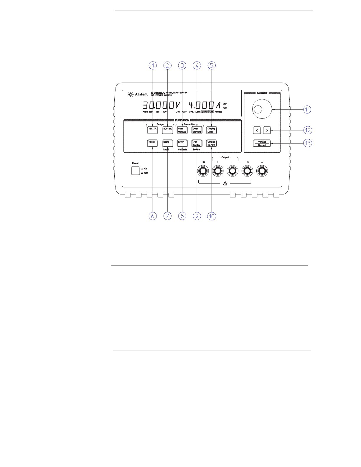
The Front Panel at a Glance
1 15V/7A range selection key
2 30V/4A range selection key
3 Overvoltage protection key
4 Overcurrent protection key
5 Display limit key
6 Recall operating state key
7 Store operating state/Local key
8 Error/Calibrate key
9 I/O Configuration/Secure key
10 Output On/Off key
11 Control knob
12 Resolution selection keys
13 Voltage/current adjust selection key
2
Page 4

1 15V/7A range selection key Selects the 15V/7A range and allows the full rated output
to 15V/7A.
2 30V/4A range selection key Selects the 30V/4A range and allows the full rated output
to 30V/4A.
3 Overvoltage protection key Enables or disables the overvoltage protection function,
sets trip voltage level, and clears the overvoltage condition.
4 Overcurrent protection key Enables or disables the overcurrent protection function,
sets trip current level, and clears the overcurrent condition.
5 Display limit key Shows voltage and current limit values on the display and allows
knob adjustment for setting limit values.
6 Recall operating state key Recalls a previously stored operating state from location
‘‘1’’, ‘‘2’’, or ‘‘3’’.
7 Store operating state / Local key1 Stores an operating state in location ‘‘1’’, ‘‘2’’, or
‘‘3’’ / or returns the power supply to local mode from remote interface mode.
8 Error / Calibrate key2 Displays error codes generated during operation, self-test and
calibration / or enables calibration mode (the power supply must be unsecured before
performing calibration). See Service Guide for more details on calibration.
9 I/O Configuration / Secure key3 Configures the power supply for remote interfaces
/ or secure or unsecure the power supply for calibration. See Service Guide for more
details on how to secure or unsecure the power supply.
10 Output On/Off key Enables or disables the power supply output. This key toggles
between on and off.
11 Control knob Increases or decreases the value of the blinking digit by turning
clockwise or counter clockwise.
12 Resolution selection keys Move the blinking digit to the right or left.
13 Voltage/current adjust selection key Selects the knob control function for voltage
or current adjustment.
1
The key can be used as the ‘‘Local’’ key when the power supply is in the remote
interfac e mode.
2
You can enable the ‘‘calibration mode’’ by holding down this key when you turn on
the power supply.
3
You can use it as the ‘‘Secure’’ or ‘‘Unsecure’’ key when the power supply is in the
calibration mode.
3
Page 5
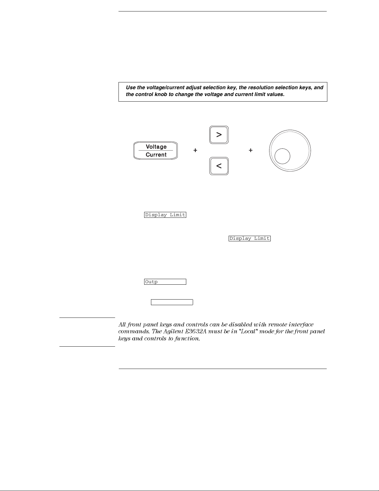
Front-Panel Voltage and Current Limit Settings
You can set the voltage and current limit values from the front panel using the
following method.
Use the voltage/current adjust selection key, the resolution selection keys, and
the control knob to change the voltage and current limit values.
1 Select the desired range using the range selection keys after turning on the power
supply.
2 Press the key to show the limit values on the display.
3 Move the blinking digit to the appropriate position using the resolution selection keys
and change the blinking digit value to the desired voltage limit by turning the control
knob. If the display limit times out, press the
4 Set the knob to current control mode using the voltage/current adjust selection key.
5 Move the blinking digit to the appropriate position using the resolution selection keys
and change the blinking digit value to the desired current limit by turning the control
knob.
6 Press the key to enable the output. After about 5 seconds, the
display will go to output monitoring mode automatically to display the voltage and
current at the output or the display will go to output monitoring mode immediately by
pressing the
Display Limit
Output On/Off
Output On/Off
key again.
Display Limit
key again.
Note
All front panel keys and controls can be disabled with remote interface
commands. The Agilent E3632A must be in "Local" mode for the front panel
keys and controls to function.
4
Page 6
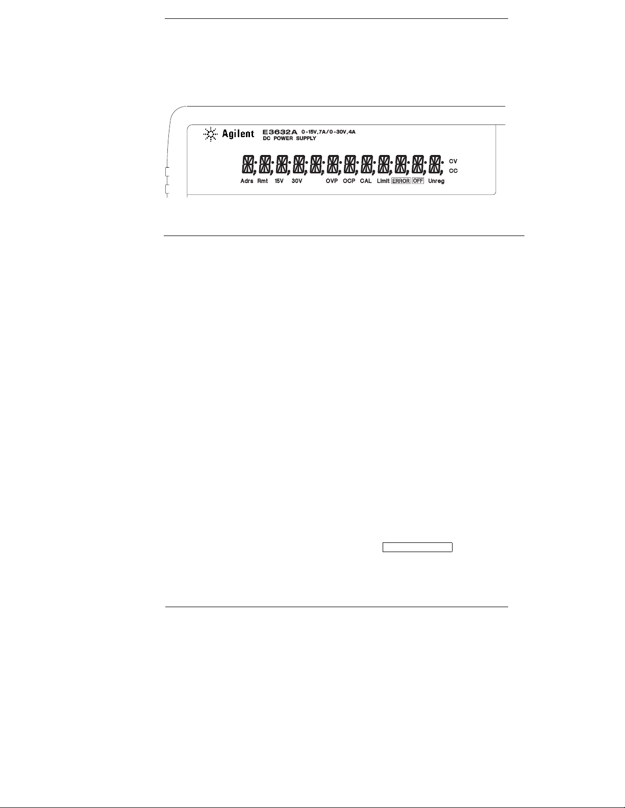
Display Annunciators
Adrs Power supply is addressed to listen or talk over a remote interface.
Rmt Power supply is in remote interface mode.
15V Shows the 15V/7A range is selected.
30V Shows the 30V/4A range is selected.
OVP The overvoltage protection function is enabled when the annunciator
OCP The overcurrent protection function is enabled when the annunciator
CAL The power supply is in calibration mode.
Limit The display shows the limit values of voltage and current.
ERROR Hardware or remote interface command errors are detected and the error
OFF The output of the power supply is disabled (See page 52 for more
Unreg The output of the power supply is unregulated (output is neither CV
CV The power supply is in constant voltage mode.
CC The power supply is in constant current mode.
turns on or the overvoltage protection circuit has caused the power
supply to shutdown when the annunciator blinks.
turns on or the overcurrent protection circuit has caused the power
supply to shutdown when the annunciator blinks.
bit has not been cleared.
information).
nor CC).
To review the display annunciators, hold down key as you
Display Limit
turn on the power supply.
5
Page 7
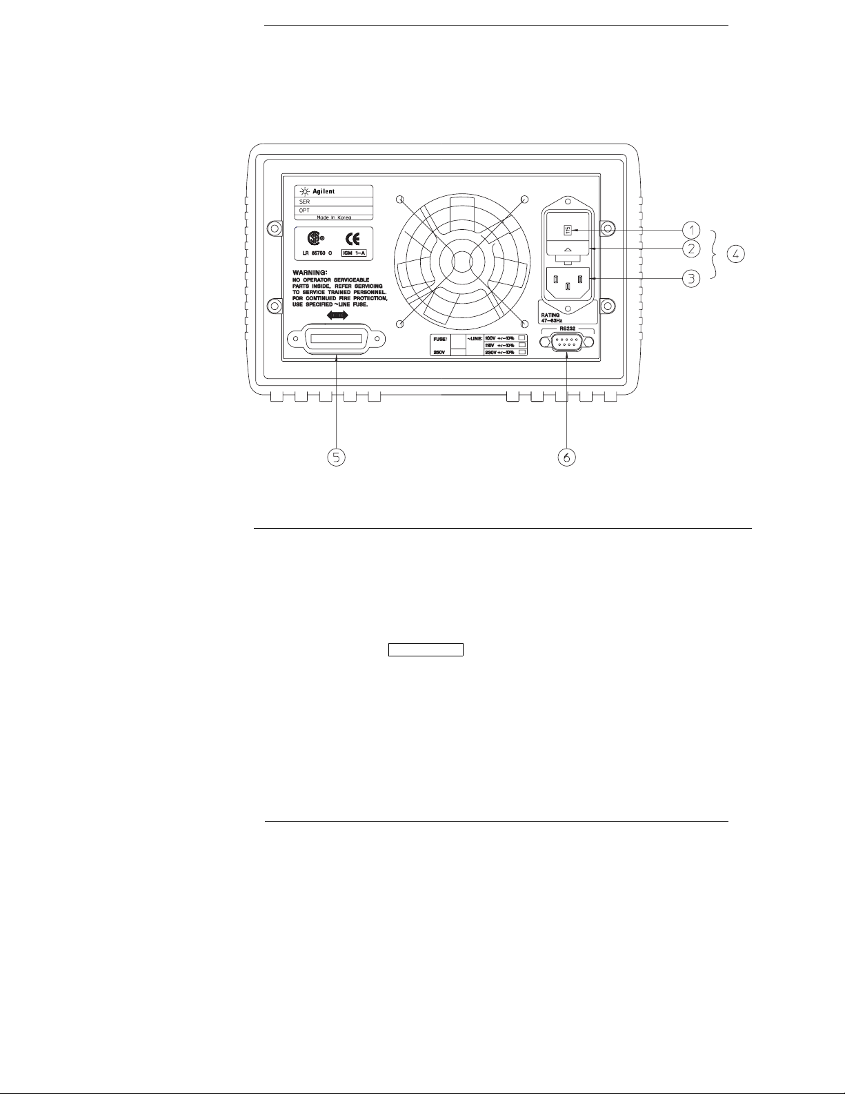
The Rear Panel at a Glance
1 Power-line voltage setting
2 Power-line fuse-holder assembly
3 AC inlet
Use the front-panel key to:
• Select the GPIB or RS-232 interface (see chapter 3).
• Set the GPIB bus address (see chapter 3).
• Set the RS-232 baud rate and parity (see chapter 3).
I/O Config
4 Power-line module
5 GPIB (IEEE-488) interface connector
6 RS-232 interface connector
6
Page 8
In This Book
General Information
supply. This chapter also provides instructions for checking your power
supply, connecting to ac power, and selecting power-line voltage.
Initial Operation
outputs and properly responds to operation from the front panel.
Front-Panel Operation
keys and how they are used to operate the power supply from the front panel.
This chapter also shows how to configure the power supply for the remote
interface and gives a brief introduction to the calibration features.
Remote Interface Reference
you program the power supply over the remote interface. This chapter also
explains how to program for status reporting.
Error Messages
working with the power supply. Each listing contains information to help you
diagnose and solve the problem.
Application Programs
to help you develop programs for your application.
Tut or ia l
gives specific details on the operation and use of the A gilent E3632A power
supply.
Specifications
Chapter 7 describes basic operation of linear power supplies and
Chapter 1 contains a general description of your power
Chapter 2 ensures that the power supply develops its rated
Chapter 3 describes in detail the use of front-panel
Chapter 4 contains reference information to help
Chapter 5 lists the error messages that may appear as you are
Chapter 6 contains some remote interface applications
Chapter 8 lists the power supply’s specifications.
If you have questions re la ting to the operation of the power suppl y, call
1-800-829-4444
Technologies Sales Office.
If your Agilen t E3632 A fail s withi n one ye ar of purc has e, A gilen t will
repair or re pl ace it free of charge . C all 1 -800-258-5165 ("Ex press
Exchan ge") in the United States , or con tact your near es t Agil ent
Technologies Sales Office.
in the United States, or contac t your ne are st A gile nt
7
Page 9

8
Page 10
Contents
Chapter 1 Gen e ral In form a tio n
Safety Considerations 14
Safety and EMC Requirements 14
Options and Accessories 15
Options 15
Accessories 15
Description 16
Installation 19
Initial Inspection 19
Cooling and Location 19
Input Power Requirements 22
Power-Line Cord 22
Power-Line Voltage Selection 22
Chapter 2 Initial Operation
Preliminary Checkout 27
Power-On Checkout 28
Output Checkout 29
Voltage Output Checkout 29
Current Output Checkout 30
Chapter 3 Fron t- Pa n el Ope rat ion
Front-Panel Operation Overview 35
Constant Voltage Operation 36
Constant Current Operation 38
Storing and Recalling Operating States 40
Programming Overvoltage Protection 42
Setting the OVP Level and Enable the OVP Circuit 42
Checking OVP Operation 43
Clearing the Overvoltage Condition 43
Programming Overcurrent Protection 45
Setting the OCP Level and Enable the OCP Circuit 45
Checking OCP Operation 46
Clearing the Overcurrent Condition 46
Remote Voltage Sensing 48
CV Regulation 48
Output Rating 48
Output Noise 48
Stability 49
Remote Voltage Sensing Connections 49
Contents
9
Page 11
Contents
Contents
Chapter 3 Front-Panel Operation (continued)
Disabling the Output 50
Disablin g the Output Using an External Relay 51
Knob Locking 51
System-Rel ated Operations 52
Self-Test 52
Error Conditions 53
Display Control 54
Firmw are Revisi on Query 55
SCPI Language Version 55
Remote Interface Configuration 56
Remote Interface Selection 56
GPIB Address 57
Baud Rate Selection (RS-232) 57
Parity Selection (RS-232) 57
To Set the GPIB Address 58
To Set the Baud Rate and Parity (RS-232) 59
GPIB Interface Configuration 61
RS-232 Interface Configuration 62
RS-232 Configurati on Overview 62
RS-232 Data Frame Format 62
Connection to a Computer or Terminal 63
DTR / DSR Handshake Protocol 64
RS-232 Troubles hooti ng 65
Calibration Overview 66
Calibration Security 66
Calibration Count 70
Calibration Message 70
10
Page 12
Contents
Chapter 4 Remote Interface Reference
SCPI Command Summary 73
Simplified Programming Overview 78
Using the APPLy Command 78
Using the Low-Level Commands 78
Reading a Query Response 79
Selecting a Trigger Source 79
Power Supply Programm ing Ranges 80
Using the APPLy Command 81
Output Setting and Operation Commands 82
Triggering Comm ands 89
Trigger Source Choices 89
Triggering Comm ands 91
System-Related Commands 92
Calibration Commands 96
RS-232 Interface Commands 99
The SCPI Status Registers 100
What is an
What is an
SCPI Status System 101
The Questionable Status Register 102
The Standard Event Register 103
The Status Byte Register 104
Using Service Request (SRQ) and Serial POLL 105
Using *STB? to Read the Status Byte 106
Using the Message Available Bit (MAV) 106
To Interrupt Your Bus Controll er Usi ng SRQ 106
To Determine When a Command Sequence is Com pl eted 107
Using *OPC to Signal When Data is in the Output Buffer 107
Status Reporting Commands 108
An Introduction to the SCPI Language 111
Command Format Used in This Manual 112
Command Separators 113
Using the
Querying Parameter Settings 114
SCPI Command Terminators 114
IEEE-488.2 Co mm on Co mm ands 114
SCPI Parameter Types 115
Halting an Output in Progress 116
SCPI Conformance Information 117
IEEE-488 Conformance Information 120
Event
Register? 100
Enable
MIN
and
Register? 100
MAX
Parameters 113
Contents
11
Page 13
Contents
Contents
Chapter 5 Error Messages
Execution Errors 123
Self-Test Errors 128
Calibration Errors 129
Chapte r 6 Applic a tio n Pro gra m s
C++ Example for GPIB(IEEE 488) 133
Excel 5.0 Example for Windows 3.1 and GPIB 135
Chapter 7 Tutorial
Overview of Agilent E3632A Operation 141
Output Characteristics 143
Unregulated State 145
Unwanted Signals 145
Connecting the Load 147
Output Isolation 147
Multiple Loads 147
Remote Voltage Sensing 148
Load Consideration 149
Extending the Voltage and Current Range 151
Series Connections 151
Parallel Connections 151
Remote Programming 152
Reliability 154
12
Chapter 8 Specifications
Performance Specifications 157
Supplemental Ch aracteristi cs 159
Index
163
Page 14

1
General Information
Page 15

General Information
This chapter provides a general description of your power supply . This chapter
also contains instructions for initial inspection, location and cooling for bench
and rack operation, selecting the power-line voltage, and connecting your
power supply to ac power.
Safety Considerations
This power supply is a Safety Class I instrument, which means that it has a
protective earth terminal. That terminal must be connected to earth ground
through a power source with a 3-wire ground receptacle.
Before installation or operation , check the power supply and review this
manual for safety markings and instructions. Safety information for specific
procedures is located at the appropriate places in this manual. See also
‘‘
Safety
’’ at the beginning of this manual for general safety information.
Safety and EMC Requirements
This power supply is designed to comply with the following safety and EMC
(Electromagnetic Compatibility) requirements:
• IEC 1010-1(1990)/EN 61010-1(1993) + A2 (1995): Safety Requirements for
Electrical Equipment for Measurement, Control, and Laboratory Use
• CSA C22.2 No.1010.1-92: Safety Requirements for Electrical Equipment for
Measurement, Control, and Laboratory Use
• UL 1244: Electrical and Electric Measuring and Testing Equipment
• EMC Directive 89/336/EEC
• Low Voltage Directive: 73/23/EEC
• EN 55011(1991) Group I, Class A/CISPR II(1990): Limits and Methods of
Radio Interface Characteristics of Industrial, Scientific, and Medical(ISM)
Radio-Frequency Equipment.
• EN50082-1(1992):
IEC 801-2(1991): Electrostatic Discharge Requirements
IEC 801-3(1984): Radiated Electromagnetic Fi eld Requi rements
IEC 801-4(1988): Electrical Fast Transient/Burst Requirements
• ICES/NMB-001
This ISM device complies with Canadian ICES-001.
Cet appareil ISM est conforme à la norme NMB-001 du Canada.
14
Page 16
Chapter 1 General Information
Options and Accessories
Options and Accessories
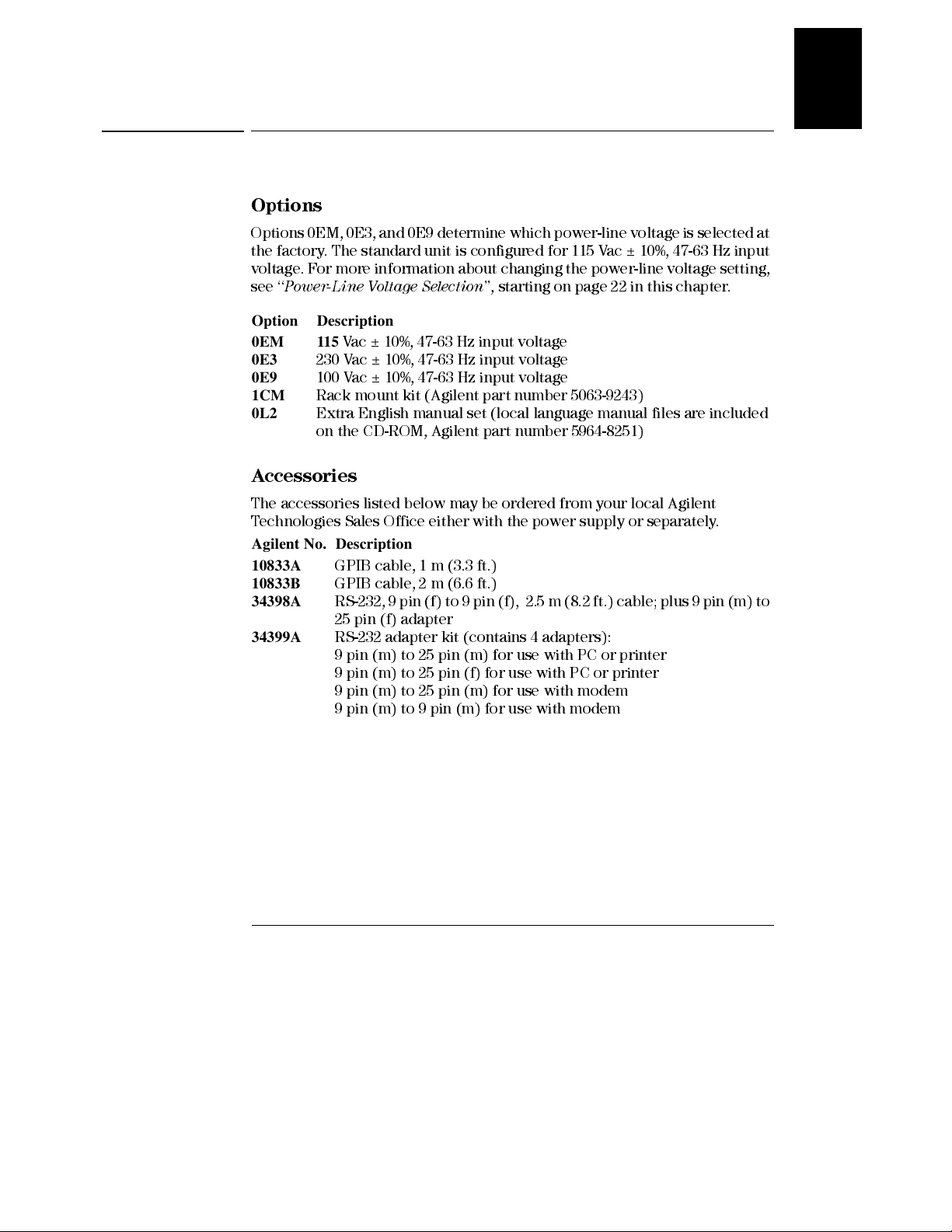
Options
Options 0EM, 0E3, and 0E9 determine which power-line voltage is selected at
the factory. The standard unit is configured for 115 Vac ± 10%, 47-63 Hz input
voltage. For more information about changing the power-line voltage setting,
see ‘‘
Power-Line Voltage Selection
Option Description
0EM 115
0E3
0E9
1CM
0L2
Vac ± 10%, 47-63 Hz input voltage
230 Vac ± 10%, 47-63 Hz input voltage
100 Vac ± 10%, 47-63 Hz input voltage
Rack mount kit (Agilent part number 5063-9243)
Extra English manual set (local language manual fil es are included
on the CD-ROM, Agi lent part number 5964-8251)
Accessories
’’, starting on page 22 in this chapter.
1
The accessories listed below may be ordered from your local Agilent
Technologies Sales Office either with the power supply or separately.
Agilent No. Description
10833A
10833B
34398A
34399A
GPIB cable, 1 m (3.3 ft.)
GPIB cable, 2 m (6.6 ft.)
RS-232, 9 pin (f) to 9 pin (f), 2.5 m (8.2 ft.) cable; plus 9 pin (m) to
25 pin (f) adapter
RS-232 adapter kit (contains 4 adapters):
9 pin (m) to 25 pin (m) for use with PC or printer
9 pin (m) to 25 pin (f) for use with PC or printer
9 pin (m) to 25 pin (m) for use with modem
9 pin (m) to 9 pin (m) for use with modem
15
Page 17
Chapter 1 General Information
Description
Description
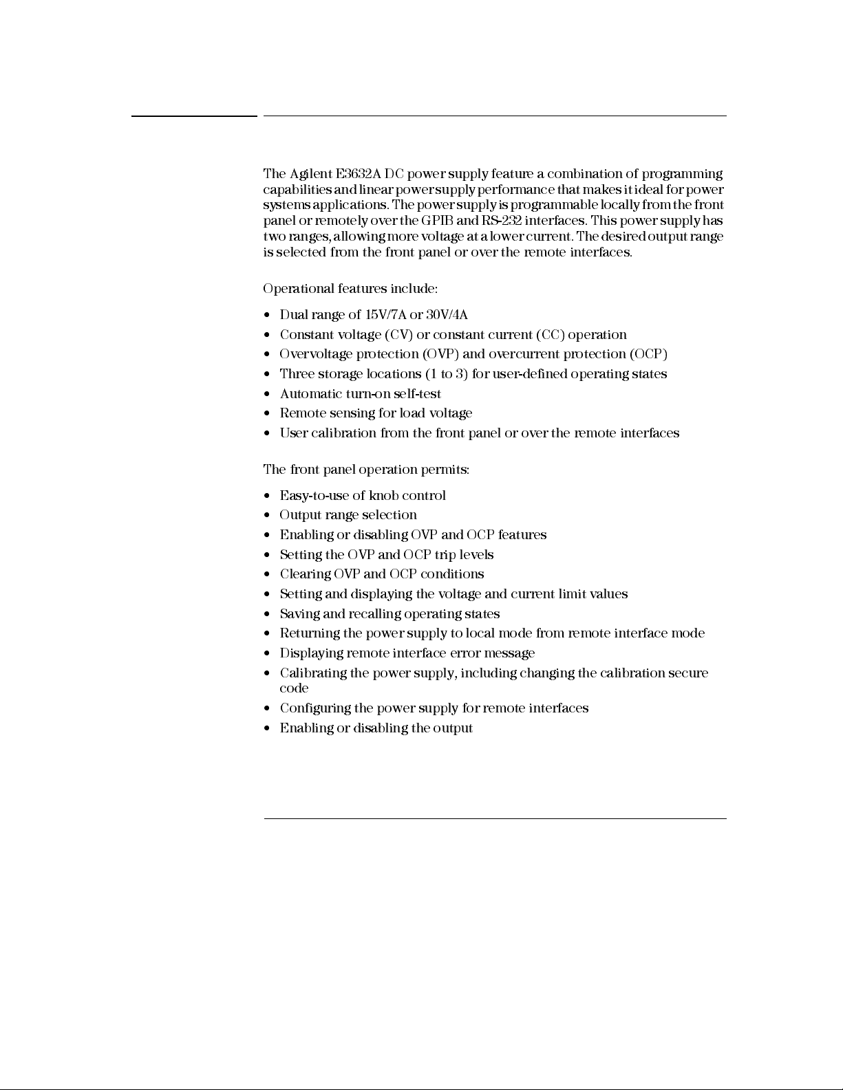
The Agilent E3632A DC power supply feature a combination of programming
capabilities and linear power supply performance that makes it ideal for power
systems applications. The power supply is programmable locally from the front
panel or remotely over the GPIB and RS-232 interfaces. This power supply has
two ranges, allowing more voltage at a lower current. The desired output range
is selected from the front panel or over the remote interfaces.
Operational features include:
• Dual range of 15V/7A or 30V/4A
• Constant voltage (CV) or constant current (CC) operation
• Overvoltage protection (OVP) and overcurrent protection (OCP)
• Three storage locations (1 to 3) for user-defined operating states
• Automatic turn-on self-test
• Remote sensing for load voltage
• User calibration from the front panel or over the remote interfaces
The front panel operation permits:
• Easy-to-use of knob control
• Output range selection
• Enabling or disabling OVP and OCP features
• Setting the OVP and OCP trip levels
• Clearing OVP and OCP conditions
• Setting and displaying the voltage and current limit values
• Saving and recalling operating states
• Returning the power supply to local mode from remote interface mode
• Displaying remote interface error message
• Calibrating the power supply, includ ing changing the calibration secure
code
• Configuring the power supply for remote interfaces
• Enabling or disabling the output
16
Page 18
Chapter 1 General Information
Description
When operated over the remote interface, the power supply can be both a
listener and a talker. Using an external controller, you can instruct the power
supply to set the output and to send the status data back over the GPIB or RS-
232. Capabilities include the following features:
• Voltage and current programming
• Voltage and current readback
• Present and stored status readback
• Programming syntax error detection
• Complete self-test
The front-panel VFD (Vacuum-Fluorescent Display) incl udes :
1
• Displaying actual values of output voltage and current (
• Or displaying the limit values of voltage and current (
• Checking the operating status from the annunciators
• Checking the type of error from the error codes (messages)
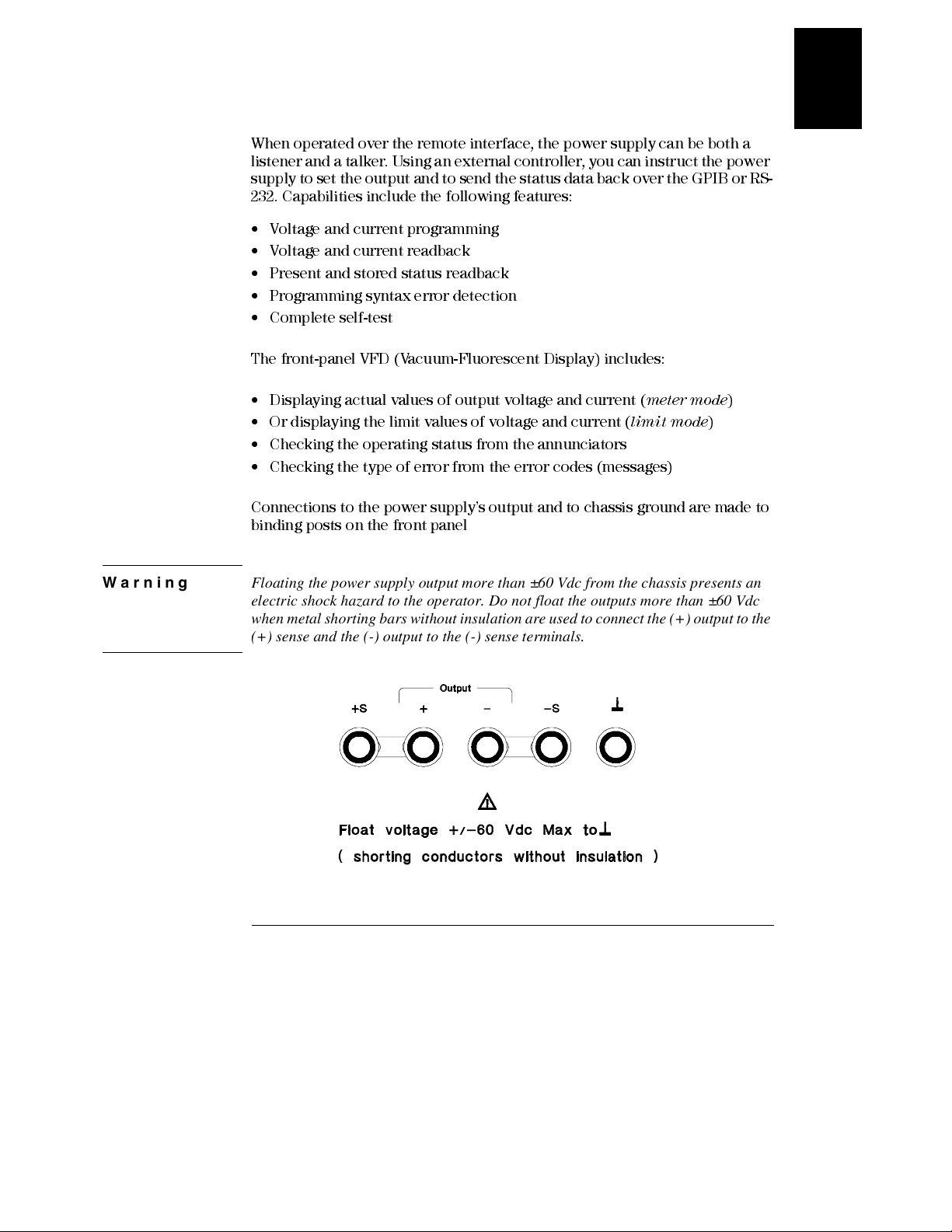
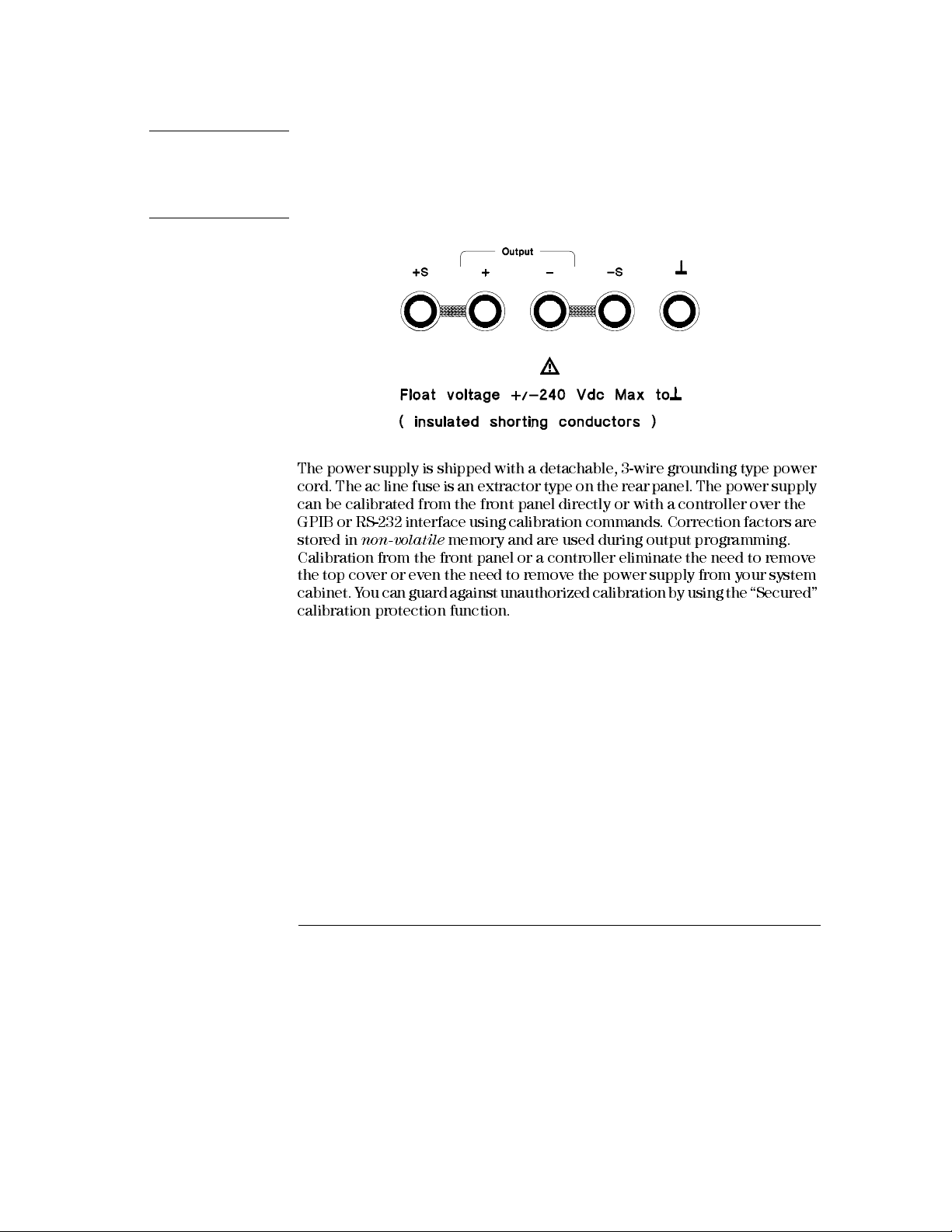
Connections to the power supply’s output and to chassis ground are made to
binding posts on the front panel
Warning Floating the power supply output more than ±60 Vdc from the chassis presents an
electric shock hazard to the operator. Do not float the outputs more than ±60 Vdc
when metal shorting bars without insulation are used to connect the (+) output to the
(+) sense and the (-) output to the (-) sense terminals.
meter mode
limit mode
)
)
17
Page 19
Chapter 1 General Information
Description
Warning Outputs can be floated to maximum of ±240 Vdc provided that the metal shorting bars
without insulation are either replaced with insulated conductors or they are removed
from the terminals so there is no operator access to the output conductors without
insulation. All field wiring insulation must be adequate for the voltage present.
The power supply is shipped with a detachable, 3-wire grounding type power
cord. The ac line fuse is an extractor type on the rear panel. The power supply
can be calibrated from the front panel directly or with a controller over the
GPIB or RS-232 interface using calibration commands. Correction factors are
stored in
Calibration from the front panel or a controller eliminate the need to remove
the top cover or even the need to remove the power supply from your system
cabinet. Y ou can guard against unauthorized calibration by using the “Secured”
calibration protection function.
non-volatile
memory and are used during output programming.
18
Page 20
Chapter 1 General Information
Installation
Installation
Initial Inspection
When you receive your power supply, inspect it for any obvious damage that
may have occurred during shipment. If any damage is found, notify the carrier
and the nearest Agilent Sales Office immediately. Warranty information is
shown in the front of this manual.
Keep the original packing materials in case the power supply has to be returned
to Agilent Technologies in the future. If you return the power supply for service,
attach a tag identifying the owner and model number. Also include a brief
description of the problem.
Mechanical Check
This check confirms that there are no broken keys or knob, that the cabinet
and panel surfaces are free of dents and scratches, and that the display is not
scratched or cracked.
1
Electrical Check
Chapter 2 describes an initial operation procedure which, when successfully
completed, verifies to a high level of confidence that the power supply is
operating in accordance with its specifications. Detailed electrical verification
procedures are included in the
Service Guide
.
Cooling and Location
Cooling
The power supply can operate without loss of performance within the
temperature range of 0 °C to 40 °C, and with derated output current from
40 °C to 55 °C. A fan cools the power supply by drawing air through the rear
panel and exhausting it out the sides. Using an Agilent rack mount will not
impede the flow of air.
Bench Operation
Y our power supply must be installed in a location that allows sufficient space
at the sides and rear of the power supply for adequate air circulation. The
rubber bumpers must be removed for rack mounting.
19
Page 21
Chapter 1 General Information
Installation
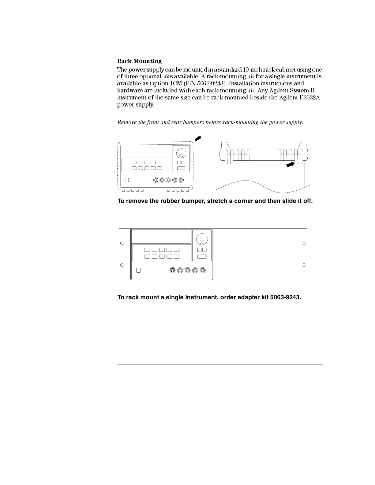
Rack Mounting
The power supply can be mounted in a standard 19-inch rack cabinet using one
of three optional kits available. A rack-mounting kit for a single instrument is
available as Option 1CM (P/N 5063-9243). Installation instructions and
hardware are included with each rack-mounting kit. Any Agilent System II
instrument of the same size can be rack-mounted beside the Agilent E3632A
power supply.
Remove the front and rear bumpers before rack-mounting the power supply.
To remove the rubber bumper, stretch a corner and then slide it off.
To rack mount a single instrument, order adapter kit 5063-9243.
20
Page 22
Chapter 1 General Information
Installation
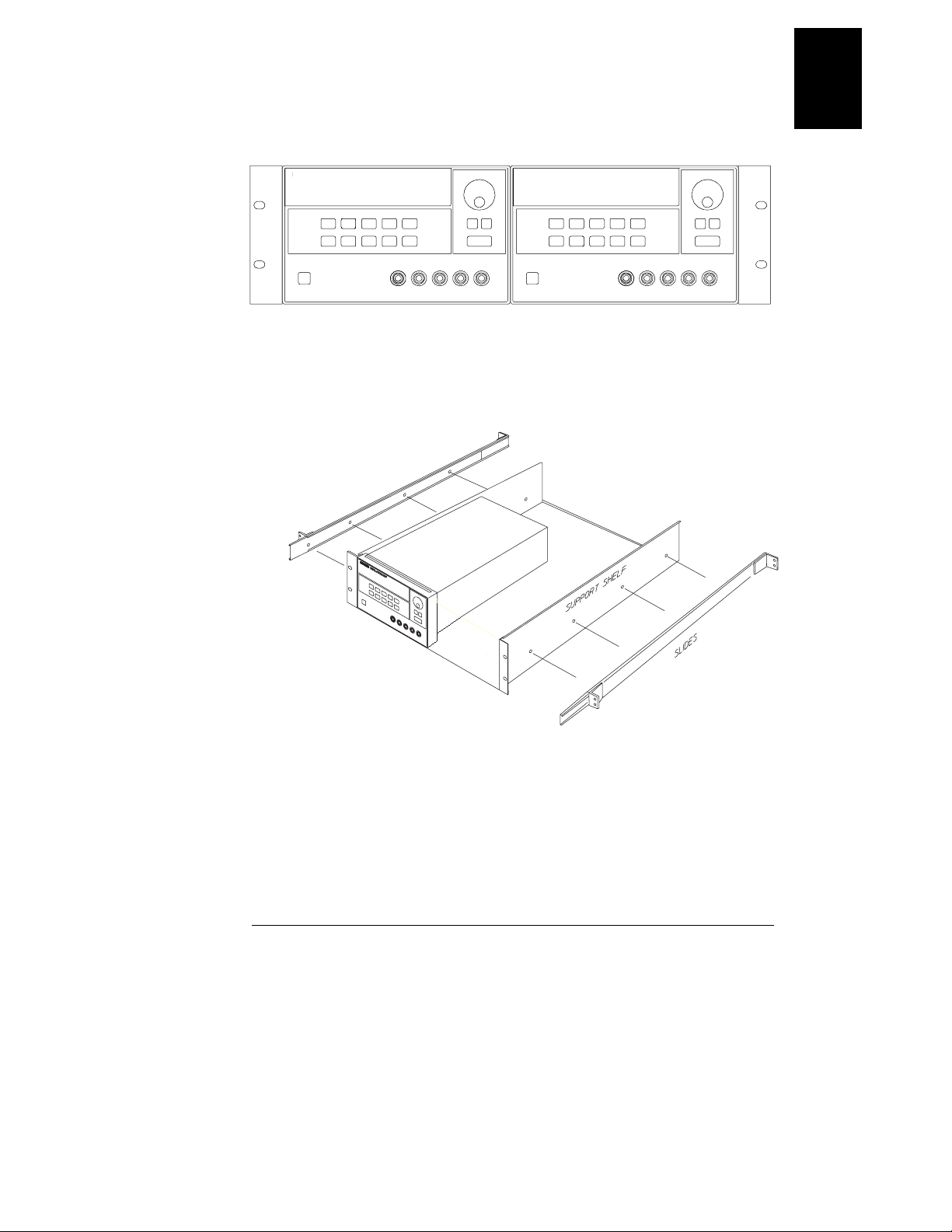
To rack mount two instrument of the same depth side-by-side, order
lock-link kit 5061-9694 and flange kit 5063-9214.
1
To install two instruments in a sliding support shelf, order support shelf
5063-9256, and slide kit 1494-0015.
21
Page 23
Chapter 1 General Information
Input Power Requirements
Input Power Requirements
Y ou can operate your power supply from a nominal 100 V, 115 V , or 230 V single
phase ac power source at 47 to 63 Hz. An indication on the rear panel shows
the nominal input voltage set for the power supply at the factory . If necessary ,
you can change the power-line voltage setting according to the instructions on
the next page.
Power-Line Cord
The power supply is shipped from the factory with a power-line cord that has
a plug appropriate for your location. Contact the nearest Agilent Technologies
Sales and Service Office if the wrong power-line cord is included with your
power supply. Your power supply is equipped with a 3-wire grounding type
power cord; the third conductor being the ground. The power supply is
grounded only when the power-line cord is plugged into an appropriate
receptacle. Do not operate your power supply without adequate cabinet
ground connection.
Power-Line Voltage Selection
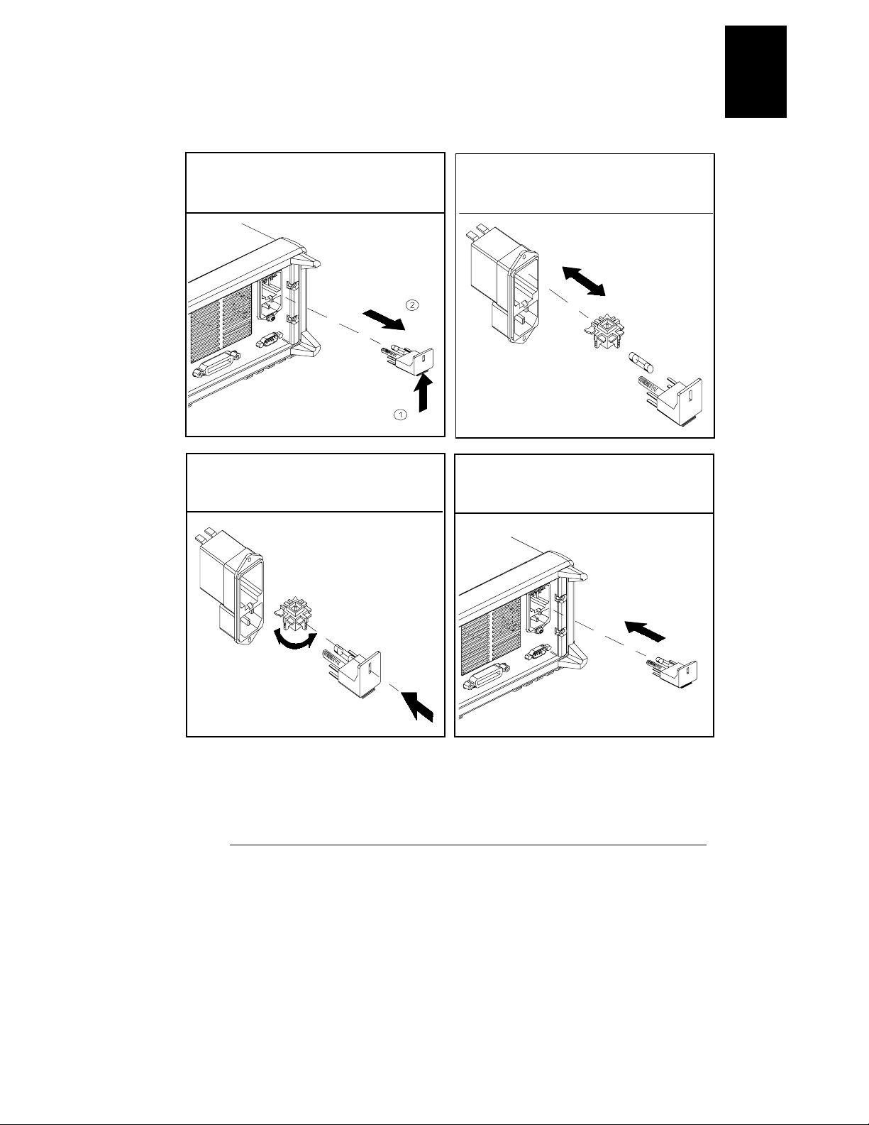
Power-line voltage selection is accomplished by adjusting two components:
power-line voltage selector and power-line fuse on the power-line module of
the rear panel. To change the power-line voltage, proceed as follows:
22
Page 24
Chapter 1 General Information
Input Power Requirements
1
1 Remove the power cord. Remove the
fuse-holder assembly with a flat-blad
screwdriver from the rear panel.
3 Rotate the power-line voltage selector
until the correct voltage appears.
2 Install the correct line fuse. Remove
the power-line voltage selector from the
power-line module.
100 or 115 Vac, 4 AT fuse
230 Vac, 2.5 AT fuse
4 Replace the power-line voltage selector
and the fuse-holder assembly in the rear
panel.
100, 115, or 230 Vac
23
Page 25

Chapter 1 General Information
Input Power Requirements
24
Page 26

Chapter 1 General Information
Input Power Requirements
1
25
Page 27

2
Initial Operation
Page 28
Initial Operation
There are three basic tests in this chapter. The automatic power-on test
includes a self-test that checks the internal microprocessors and allows the
user visually to check the display. The output check ensures that the power
supply develops its rated outputs and properly responds to operation from the
front panel. For complete performance and/or verification tests, refer to the
Service Guide
This chapter is intended for both the experienced and the inexperienced user
because it calls attention to certain checks that should be made prior to
operation.
Throughout this chapter the key to be pressed is shown in the left margin.
.
26
Page 29
Chapter 2 Initial Operation
Preliminary Checkout
Preliminary Checkout
The following steps help you verify that the power supply is ready for use.
1
Verify the power-line voltage setting on the rear panel.
The power-line voltage is set to the proper value for your country when the
power supply is shipped from the factory. Change the voltage setting if it is not
correct. The settings are: 100, 115, or 230 Vac.
2
Verify that the correct power-line fuse is installed.
The correct fuse is installed for your country when the power supply is shipped
from the factory. For 100 or 115 Vac operation, you must use a 4 AT fuse. For
230 Vac operation, you must use a 2.5 AT fuse.
3
Connect the power-line cord and turn on your power supply.
The front-panel display will light up and a power-on self-test occurs
automatically when you turn on the power supply.
See "Power-Line Voltage Selection", starting on page 22 in chapter 1 if you
need to change the power-line voltage or the powe r-line fuse .
To replace the 4 AT fuse, order Agilent part number 2110-0996.
To replace the 2.5 AT fuse, order A gile nt part nu m ber 2110-0999.
2
27
Page 30
Chapter 2 Initial Operation
Power-On Checkout
Power-On Checkout
The power-on test includes an automatic self-test that checks the internal
microprocesso rs and allow s the user visuall y to check the display. You will
observe the following sequence on the display after pressing the front panel
power switch to on.
1 All segments of the display including all annunciators will turn on for about one
second.
To review the annunciators, hold down key as you turn on
the power suppl y
.
2 The GPIB address or RS-232 message will then be displayed for about one
second.
ADDR 05 (or RS-232)
The GPIB address is set to ‘‘5’’ when the power supply is shipped from the
factory for remote interface configuration. If this is not the first time the power
supply is turned on, a different interface (RS-232) or a different GPIB address
may appear.
See "Remote Interface Configuration" in chapter 3 starting on page 56 if you
need to change the remote interface configuration.
Display Limit
Output On/Off
Note
3The “15V”, “OVP”, “OCP” and “OFF” annunciators are on. All others are off.
The power supply will go into the
(the
OFF
annunciator turns on); the 15V/7A range is selected (the
annunciator turns on); and the knob is selected for
OVP
and
OCP
the
annunciator also turn on.
power-on / reset
state; the output is disabled
15V
voltage
control. Notice that
4 Enable the outputs.
Press the key to enable the output. The
off and the
Output On/Off
15V, OVP, OCP
OFF
, and CV annunciators are lit. The
annunciator turns
blinking
digit can
be adjusted by turning the knob. Notice that the display is in the meter mode.
‘‘Meter mode’’ means that the display shows the actual output voltage and
current.
If the power supply detects an error during power-on self-test, the
annunciator will turn on.
See "Error Messages" for more information
ERROR
starting on page 121 in chapter 5
28
Page 31

Power
Output On/Off
Chapter 2 Initial Operation
Output Checkout
Output Checkout
The following procedures check to ensure that the power supply develops its
rated outputs and properly responds to operation from the front panel. For
complete performance and verification tests, refer to the
For each step, use the keys shown on the left margins.
Voltage Output Checkout
The following steps verify basic voltage functions with no load.
1 Turn on the power supply.
The power supply will go into the
OFF
(the
annunciator turns on); and the knob is selected for
2 Enable the outputs.
The
lit. The
display is in the meter mode. ‘‘Meter mode’’ means that the display shows the
actual output voltage and current.
annunciator turns on); the 15V/7A range is selected (the
OFF
annunciator turns off and the
blinking
digit can be adjusted by turning the knob. Notice that the
power-on / reset
15V, OVP, OCP
state; the output is disabled
Service Guide
15V
voltage
control.
, and CV annunciators are
.
2
3
Check that the front-panel voltmeter properly responds to knob control for the 15V/7A range.
Turn the knob clockwise or counter clockwise to check that the voltmeter
responds to knob control and the ammeter indicates nearly zero.
4
Ensure that the voltage can be adjusted from zero to the full rated
value.
Adjust the knob until the voltmeter indicates 0 volts and then adjust the knob
until the voltmeter indicates ‘‘
1
You can use the resolution selection keys to move the blinking digit to the
right or left when settin g the voltage.
1
15.0
volts’’.
29
Page 32
Power
Chapter 2 Initial Operation
Output Checkout
Current Output Checkout
The following steps check basic current functions with a short across the
power supply’s output.
1
Turn on the power supply.
The power supply will go into the
OFF
(the
annunciator turns on); the 15V/7A range is selected (the
annunciator turns on); and the knob is selected for
2
Conne c t a s hor t a c r os s (+) and ( - ) o utp ut te r mi n a ls wi th an in s ulated test lead.
power-on / reset
state; the output is disabled
15V
voltage
control.
Output On/Off
Display Limit
Volt/Curr
3
Enable the output.
The
OFF
The
CV
or CC annunciator turns on depending on the resistance of the test
lead. The
annunciator turns off and the
blinking
digit can be adjusted by turning the knob. Notice that the
15V, OVP
, and
OCP
annunciators are lit.
display is in the meter mode. ‘‘Meter mode’’ means that the display shows the
actual output voltage and current.
4
Adjust the voltage limit value to 1.0 volt.
Set the display to the
Adjust the voltage limit to 1.0 volt to assure CC operation. The
limit
mode (the
Limit
annunciator will be
blinking
CC
annunciator
will turn on.
5
Check that the front-panel ammeter properly responds to knob control for the 15V/7A range.
Set the knob to the
clockwise when the display is in the meter mode (the
current
control, and turn the knob clockwise or counter
Limit
annunciator is off).
Check that the ammeter responds to knob control and the voltmeter indicates
nearly zero (the voltmeter will show the voltage drop caused by the test lead).
).
30
Page 33

Chapter 2 Initial Operation
Output Checkout
6
Ensure that the current can be adjusted from zero to the full rated value.
Note
Adjust the knob until the ammeter indicates 0 amps and then until the ammeter
indicates 7.0 amps.
If an error has been detec ted dur ing the outpu t chec kout proce dur es , the
ERROR
starting on page 121 in chapter 5.
annu nciat or will turn o n. See "Error Messages" for more information
1
2
1
You can use the resolution selection keys to move the blinking digit the right
or left when setting the cu rr en t.
31
Page 34

Chapter 2 Initial Operation
Output Checkout
32
Page 35

3
Front-Panel Operation
Page 36

Front-Panel Operation
So far you have learned how to install your power supply and perform initial
operation. During the initial operation , you were briefly introduced to
operating from the front panel as you learned how to check basic voltage and
current functions. This chapter will describe in detail the use of these front-
panel keys and show how they are used to accomplish power supply operation.
• Front-Panel Operation Overview, page 35
• Constant Voltage Operation, page 36
• Constant Current Operation, page 38
• Storing and Recalling Operating States, page 40
• Programmin g Overvoltage Protection, page 42
• Programming Overcurrent Protection, page 45
• Remote Voltage Sensing, page 48
• Disabling the Output, page 50
• Disabling the Output Using an External Relay, page 51
• Knob Locking, page 51
• System-Related Operations , page 52
• Remote Interface Configuration, page 56
• GPIB Interface Configuration, page 61
• RS-232 Interface Configuration, page 62
• Calibration Overview, page 66
Note
Throughout this chapter the key to be pressed is shown in the left margin.
See "Error Messages", starting on page 121 in chapter 5 if you encounter any
errors dur ing front-pan el opera tion.
34
Page 37
Chapter 3 Front-Panel Operation
Front-Panel Operation Overview
Front-Panel Operation Overview
The following section describes an overview of the front-panel keys before
operating your power supply.
• The power supply is shipped from the factory configured in the
operation mode. At power-on, the power supply is autom aticall y set to
operate in the front-panel operation mode. When in this mode, the front-
panel keys can be used. When the power supply is in
remote
you can return to front-panel operation mode at any time by pressing the
Local
key if you did not previously send the front-panel lockout command.
A change between front-panel and remote operation modes will
in a change in the output parameters.
• The power supply has two output ranges of 15V/7A or 30V/4A. This feature
allows more voltage at a lower current or more current at a lower voltage.
The desired output range is selected from the front panel or over the remote
15V
or
30V
interfaces. The
annunciator indicates the presently selected
range.
• When you press key (the
display of the power supply goes to the
Display Limit
Limit
annunciator blinks), the
limit
mode and the present limit
values will be displayed. In this mode, you can also observe the change of
the limit values when adjusting the knob. If you press the
key again or let the display time-out after several seconds, the power supply
Limit
will return the display to the
meter
mode (the
annunciator turns off).
In this mode, the actual output voltage and current will be displayed.
• The output of the power supply can be enabled or disabled from the front
panel using the
Output On/Off
key. When the output is off, the
annunciator turns on and the output is disabled.
• The display provides the present operating status of the power supply with
annunciators and also informs the user of error codes. For example, the
power supply is operating in CV mode in the 15V/7A range and controlled
CV
and
15V
from the front panel, then the
however, the power supply is remotely controlled, the
annunciators will turn on. If,
Rmt
also turn on, and when the power supply is being addressed over GPIB
interface, the
Adrs
annunciator will turn on. See "
Display A nnu nc iators
on page 5 for more information.
front-panel
operation mode,
not
result
Display Limit
OFF
annunciator will
"
3
35
Page 38

Power
Chapter 3 Front-Panel Operation
Constant Voltage Operation
Constant Voltage Operation
To set up the power supply for constant voltage (CV) operation, proceed as
follows.
• Front-panel operation:
1
Connect a load to the output terminals.
With power-off, connect a load to the (+) and (-) output terminals.
2
Turn on the power supply.
Display Limit
Volt/Curr
The power supply will go into the
OFF
(the
annunciator turns on); the 15V/7A range is selected (the
annunciator turns on); and the knob is selected for
T o operate the power supply in the 30V/4A range, press the key bef ore
proceeding to the next step. The
3
Set the display to the limit mode.
Not i c e that the
Limit
annunciator blinks, indicating that the display is in the
limit mod e. Wh en the dis pla y is in t he
power-on / reset
30V
annunciator turns on.
limit
state; the output is disabled
mode, you can see the voltage and
voltage
control.
30V,4A
15V
current limit values of the power supply.
In constant voltage mode, the voltage values between the meter and limit
modes ar e the sam e , but the cu rr en t value s are not. Mor eover, if the
display is in the meter mode, you cannot see the change of current limit
value when adjusting the knob. We recommend that you should set the
display to “lim it” m ode to see the chan ge of curr en t lim it valu e in the
constant voltage mode whenever adjusting the knob.
4
Adjust the knob for the desired current limit.
Check that the
The second digit of the ammeter will be
Limit
annunciator still blinks. Set the knob for
blinking
1
current
control.
. The blinking digit can be
changed using the resolution selection keys and the blinking digit can be
adjusted by turning the knob. Adjust the knob to the desired current limit.
1
You can use the resolution selection keys to move the blinking digit to the
right or left when settin g curr en t.
36
Page 39
Chapter 3 Front-Panel Operation
Constant Voltage Operation
Volt/Curr
Display Limit
Output On/Off
5
Adjust the knob for the desired output voltage.
Check that the
The second digit of the voltmeter will be
Limit
annunciator still blinks. Set the knob for
blinking
1
voltage
control.
. Change the blinking digit
using the resolution selection keys and adjust the knob to the desired output
voltage.
6
Return to the meter mode.
Display Limit
Press key or let the display time-out after several seconds to
return to the meter mode. Notice that the
Limit
annunciator turns off and the
display shows “OUT PUT OFF” mes sage.
7
Enable the output.
The
OFF
annunciator turns off and the
15V
or
30V, OVP, OCP
and CV
annunciators are lit. Notice that the display is in the meter mode. In the
mode, the display shows the actual output voltage and current.
Refer to “Programming Overvoltage Protection” and “Programming
Overcurrent Protection” sections, starting on
information on
8
Verify that the power supply is in the constant voltage mode.
OVP
and
OCP
annunciators.
page 42 and page 45 for more
If you operate t he power supply in the constant v oltage (CV) mode, verify that
the
CV
annunciator is lit. If the CC annunciator is lit, choose a
higher
current
limit.
meter
3
Note
During actual CV operation, if a load change causes the current limit to be
exceeded, the power supply will automatically crossover to the constant
curren t mode at the prese t cur re nt lim i t and the output voltage wil l drop
proportionately.
• Remote inte rfac e oper ation:
CURRent {<current>|MIN|MAX} Set the current
VOLTage {<voltage>|MIN|MAX Set the voltage
OUTPut ON Enable the output
1
You can use the resolution selection keys to move the blinking digit to the
right or left when settin g voltage.
37
Page 40
Power
Chapter 3 Front-Panel Operation
Constant Current Operation
Constant Current Operation
To set up the power supply for constant current (CC) operation, proceed as
follows.
• Front-panel operation:
1
Connect a load to the output terminals.
With power-off, connect a load to the (+) and (-) output terminals.
2
Turn on the power supply.
Display Limit
The power supply will go into the
OFF
(the
annunciator turns on); the 15V/7A range is selected (the
annunciator turns on); and the knob is selected for
To operate the power supply in the 30V/4A range, press key before
proceeding to the next step. The
3
Set the display to the limit mode.
Not i c e that the
Limit
annunciator blinks, indicating that the display is in the
limit mod e. Wh en the dis pla y is in t he
power-on / reset
30V
annunciator turns on.
limit
state; the output is disabled
mode, you can see the voltage and
voltage
30V,4A
control.
15V
current limit values of the selected supply.
In constant current mode, the current values between the meter mode and
limit mode are the same, but the voltage values are not. Moreover, if the
display is in the meter mode, you cannot see the change of voltage limit
value when adjusting the knob. We recommend that you should set the
display to “limit” mode to see the change of voltage limit value in the
constant current mode whenever adjusting the knob.
4
Adjust the knob for the desired voltage limit.
Check that the
blinks
to indicate the knob is selected for voltage control. The blinkin g digit
Limit
annunciator still blinks and the second digit of voltmeter
1
can be changed using the resolution keys and the blinking digit can be adjusted
by turning the knob. Adjust the knob for the desired voltage limit.
1
You can use the resolution selection keys to move the blinking digit to the
right or left when settin g the voltage.
38
Page 41
Chapter 3 Front-Panel Operation
Constant Current Operation
Volt/Curr
Display Limit
Output On/Off
5
Adjust the knob for the desired output current.
Check that the
The second digit of the ammeter will be
Limit
annunciator still blinks. Set the knob for
blinking
. Change the blinking digit
1
current
control.
using the resolution selection keys and adjust the knob to the desired output
current.
6
Return to the meter mode.
Display Limit
Press key or let the display time-out after several seconds to
return the meter mode. Notice that the
Limit
annunciator turns off and the
display shows “OUT PUT OFF” mes sage.
7
Enable the output.
The
OFF
annunciator turns off and the
15V
or
30V, OVP, OCP
and CC
annunciators are lit. Notice that the display is in the meter mode. In the
mode, the display shows the actual output voltage and current.
Refer to “Programming Overvoltage Protection” and “Programming
Overcurrent Protection” sections, starting on
information on
8
Verify that the power supply is in the constant current mode.
OVP
and
OCP
annunciators.
page 42 and page 45 for more
If you operate the power supply in the constant current (CC) mode, verify that
the
CC
annunciator is lit. If the CV annunciator is lit, choose a
higher
voltage
limit.
meter
3
Note
During actual CC operation , if a load chan ge cau se s the voltage l im it to be
exce ed ed , t he power supply wi ll au t o ma t i ca lly crossov er to constant v o l t a g e
mode at the preset voltage limit and the output current will drop
proportionately.
• Remote inte rfac e oper ation:
VOLTage {<voltage>|MIN|MAX} Set the voltage
CURRent {<current>|MIN|MAX} Set the current
OUTPut ON Enable the output
1
You can use the resolution selection keys to move the blinking digit to the
right or left when settin g the cur ren t.
39
Page 42

Chapter 3 Front-Panel Operation
Storing and Recalling Operating States
Storing and Recalling Operating States
Store
You can store up to three different operating states in
This also enables you to recall the entire instrument configuration with just a
few key presses from the front panel.
The memory locations are suppli ed with the reset states from the factory for
front-panel operation. Refer to the description of
page 94 in chapter 4 for more information. The following steps show you how
to store and recall an operating state.
• Front-panel operation:
1
Set up the power supply for the desired operating state.
The storage feature “remembers” output range selection, the limit value
settings of voltage and current, output on/off state, OVP and OCP on/off state,
and OVP and OCP trip levels.
2
Turn on the storage mode.
Three memory locations (numbered 1, 2 and 3) are available to store the
operating states. The operating states are stored in
are remembered when being recalled.
non-volatile
*RST
command, starting on
non-volatile
memory and
memory.
STORE 1
This mes sage appear s on the dis pla y for approxim ate ly 3 se cond s.
3
Store the operating state in memory location “3”.
Turn the knob to the right to specify the memory location 3.
STORE 3
To cancel the store operation, let the display time-out after about 3 seconds
Store
or press any other function key except the
returns to the normal operating mode and to the function pressed.
40
key. The power suppl y
Page 43
Chapter 3 Front-Panel Operation
Storing and Recalling Operating States
Store
Recall
4
Save the operating state.
The operating state is now stored. To recall the stored state, go to the following
steps.
DONE
This mes sage appear s on the dis pla y for approxim ate ly 1 se cond .
5
Turn on the recall mode.
Memory location “1” will be displ ayed in the recall mode.
RECALL 1
This mes sage appear s on the dis pla y for approxim ate ly 3 se cond s.
6
Recall the stored operating state.
Turn the knob to the right to change the displayed storage location to 3.
RECALL 3
3
Recall
If this setting is not followed within 3 seconds with key stroke, the
power suppl y retu rns to norm al oper atin g mode an d wil l not rec all the
instrument state 3 from memory.
7
Restore the operating state.
The power supply should now be configured in the same state as when you
stored the state on the previous steps.
Recall
DONE
This mes sage appear s on the dis pla y for approxim ate ly 1 se cond .
• Remote inte rfac e oper ation:
*SAV {1|2|3} Store an operating state to a specified location
*RCL {1|2|3} Recall a previously stored state from a specified location
41
Page 44

Chapter 3 Front-Panel Operation
Programming Overvoltage Protection
Programming Overvoltage Protection
Overvoltage protection guards the load against output voltages that reach a
specified value greater than the programmed protection level. It is
accomplished by shorting the output via an internal SCR when the trip level is
set to equal or greater than 3 volts, or by progamming the output to 1 volt when
the trip level is set to less than 3 volts.
The following steps show how to set the OVP trip level, how to check OVP
operation, and how to clear overvoltage condition.
• Front-panel operation:
Setting the OVP Level and Enable the OVP Circuit
Power
Output On/Off
Over Voltage
Note
Over Voltage
1
Turn on the power supply.
The power supply will go into the
OFF
(the
annunciator turns on); and the knob is selected for
2
Enable the output.
The
3
Enter the OVP menu and set the trip level.
annunciator turns on); the 15V/7A range is selected (the
OFF
annunciator turns off and the display will go to the meter mode.
power-on / reset
state; the output is disabled
15V
voltage
control.
LEVEL 32.0 V
Y ou will see the above message on the display when you enter the OVP menu.
Adjust the control knob for the desired OVP trip level.
Note that you cannot set the trip level s to lower than 1.0 volt.
4
Enable the OVP circuit.
OVP ON
You will see the above message after pressing key.
Over Voltage
42
Page 45

Chapter 3 Front-Panel Operation
Programming Overvoltage Protection
Over Voltage
5
Exit the OVP menu.
CHANGED
The “CHANGED” mess age is highli ghted for a second to show that the new
OVP trip level is now in effect. If the OVP settings are not changed, “NO
CHANGE” will be displayed. The power supply will exit the OVP menu and the
OVP
display will return to the meter mode. Check that the
on.
annunciator turns
Checking OVP Operation
To check OVP operation, raise the output voltage to near the trip point. Then
very gradually increase the output by turning the knob until the OVP circuit
trips. This will cause the power supply output to drop to near zero, the
CC
annunciator to
message also appears on the display.
blink
, and the
annunciator to turn on. The “OVP TRIPPED”
Clearing the Overvoltage Condition
When the OVP condition occurs (the “OVP TRIPPED” message is shown on
the display), the
voltage source such as a battery, disconnect it first. The following steps show
how to clear the overvoltage conditions and get back to normal mode
operation. In the following steps, the display will go back to "OVP TRIPPED"
if you let the display time out after about several seconds.
OVP
annunciator
blinks
. When it was caused by external
OVP
3
Over Voltage
Display Limit
Over Voltage
or
1
Readjust the OVP trip level or the output voltage level.
Lower the output voltage level below the OVP trip point after pressing the
Display Limit
Over Voltage
the key.
2
Move to the clear mode.
ovp on
You will see the above message after pressing the key. If you
changed the output voltage level, press the key twice. Turn the
knob to the right until the "OVP CLEAR" appears on the display.
or raise the OVP trip level by using the knob after pressing
Over Voltage
Over Voltage
43
Page 46

Chapter 3 Front-Panel Operation
Programming Overvoltage Protection
Over Voltage
Note
3
Clear the overvoltage condition and exit this menu.
Now, when you press key again, the “DONE” message is
displayed for a second and the
Over Voltage
OVP
annunciator will not blink any more. The
output will return to meter mode.
• Remote inte rfac e oper ation:
VOLT:PROT {<voltage>|MIN|MAX} Set the OVP level
VOLT:PROT:STAT {OFF|ON) Disable or enable the OVP circuit
VOLT:PROT:CLE Clear the tripped OVP circuit
The power supply’s OVP circuit contains a crowbar SCR, which effectively
shorts the output of the power supply whenever the overvoltage condition
occurs. If external voltage source such as a battery is connected across the
output, and the overvoltage cond ition ina dver tentl y occu rs, the SC R w ill
continuousl y sin k a large cu rr en t from the sourc e; possi bly dam agin g the
power suppl y. To avoid this a diode m us t be conne cte d in se rie s with the
output as shown below.
Figure 3-1. Recommended Protection Circuit for Battery Charging
44
Page 47

Chapter 3 Front-Panel Operation
Programming Overcurrent Protection
Programming Overcurrent Protection
Overcurrent protection guards the load against output currents that reach a
specified value greater than the programmed protection level. It is
accomplished by programm ing the output current to zero.
The following steps show how to set the overcurrent protection trip level, how
to check OCP operation and how to clear overcurrent condition.
• Front-panel operation:
Power
Output On/Off
Over Current
Over Current
Setting the OCP Level and Enable the OCP Circuit
1
Turn on the power supply.
The power supply will go into the
OFF
(the
annunciator turns on); and the knob is selected for
2
Enable the output.
The
3
Enter the OCP menu and set the trip level.
Y ou will see the above message on the display when you enter the OCP menu.
Adjust the knob for the desired OCP trip level.
4
Enable the OCP circuit.
annunciator turns on); the 15V/7A range is selected (the
OFF
annunciator turns off and the display will go to the meter mode.
LEVEL 7.5 A
power-on / reset
state; the output is disabled
15V
voltage
control.
OCP ON
You will see the above message after pressing the key.
Over Current
3
45
Page 48
Chapter 3 Front-Panel Operation
Programming Overcurrent Protection
Over Current
5
Exit the OCP menu.
CHANGED
The “CHANGED” message is displayed for a second to show that the new OCP
trip level is now in effect. If the OCP settings are not changed, “NO CHANGE”
will be displayed. The power supply will exit the OCP menu and the display
OCP
will return to the meter mode. Check that the
annunciator turns on.
Checking OCP Operation
To check OCP operation, raise the output current to near the trip point. Then
very gradually increase the output by turning the knob until the OCP circuit
trips. This will cause the power supply’s output current to drop to zero and the
OCP
annunciator to
blink
. The “OCP TRIPPED” message also appears on the
display.
Clearing the Overcurrent Condition
When the OCP condition occurs (the “OCP TRIPPED” message is shown on
the display), the
voltage source such as a battery, disconnect it first. The following steps show
how to clear the overcurrent conditions and get back to normal mode
operation. In the following steps, the display will go back to "OCP TRIPPED"
if you let the display time out after about several seconds.
OCP
annunciator blinks. When it was caused by external
Over Current
Display Limit
or
1
Readjust the OCP trip level or the output current level.
Lower the output current level below the OCP trip point after pressing the
Display Limit
Over Current
the key.
2
Move to the clear mode.
or raise the OCP trip level by using the knob after pressing
ocp on
You will see the above message after pressing the key. If you
changed the output current level, press the key twice. Turn the
Over Current
Over Current
knob to the right until the "OCP CLEAR" appears on the display.
46
Page 49

Chapter 3 Front-Panel Operation
Programming Overcurrent Protection
Over Current
3
Clear the overcurrent condition and exit this menu.
Now, when you press key again, the “DONE’’ message is
displayed for a second and the
output will return to meter mode.
• Remote inte rfac e oper ation:
CURR:PROT {<current>|MIN|MAX} Set the OCP level
CURR:PROT:STAT {OFF|ON} Disable or enable the OCP circuit
CURR:PROT:CLE Clear the tripped OCP circuit
Over Current
OCP
annunciator will not blink any more. The
3
47
Page 50
Chapter 3 Front-Panel Operation
Remote Voltage Sensing
Remote Voltage Sensing
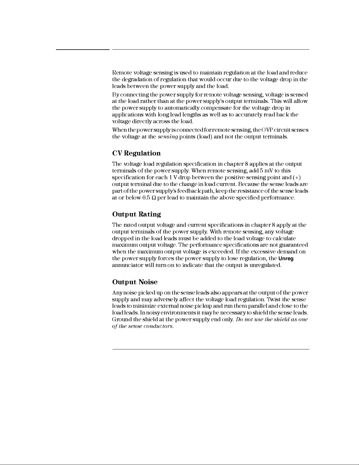
Remote voltage sensing is used to maintain regulation at the load and reduce
the degradation of regulation that would occur due to the voltage drop in the
leads between the power supply and the load.
By connecting the power supply for remote voltage sensing, voltage is sensed
at the load rather than at the power supply’s output terminals. This will allow
the power supply to automatically compensate for the voltage drop in
applications with lo ng lead lengths as well as to accurately read back the
voltage directly across the load.
When the power supply is connected for remote sensing, the OVP circuit senses
the voltage at the
CV Regulation
The voltage load regulation specification in chapter 8 applies at the output
terminals of the power supply. When remote sensing, add 5 mV to this
specification for each 1 V drop between the positive sensi ng point and (+)
output terminal due to the change in load current. Because the sense leads are
part of the power supply’s feedback path, keep the resistance of the sense leads
at or below 0.5
sensing
Ω
per lead to maintain the above specified performance.
points (load) and not the output terminals.
Output Rating
The rated output voltage and current specifications in chapter 8 apply at the
output terminals of the power supply. With remote sensing, any voltage
dropped in the load leads must be added to the load voltage to calculate
maximum output voltage. The performance specifications are not guaranteed
when the maximum output voltage is exceeded. If the excessive demand on
Unreg
the power supply forces the power supply to lose regulation, the
annunciator will turn on to indicate that the output is unregulated.
Output Noise
Any noise picked up on the sense leads also appears at the output of the power
supply and may adversely affect the voltage load regulation. Twist the sense
leads to minimize external noise pickup and run them parallel and close to the
load leads. In noisy environments it may be necessary to shield the sense leads.
Ground the shield at the power supply end only.
of the sense conductors
48
.
Do not use the shield as one
Page 51

Chapter 3 Front-Panel Operation
Remote Voltage Sensing
Stability
Using remote sensing under certain combinations of load lead lengths and
large load capacitances may cause your application to form a filter, which
becomes part of the voltage feedback loop. The extra phase shift created by
this filter can degrade the power supply’s stability, resulting in poor transient
response or loop instability. In severe cases, it may cause oscillations. To
minimize this possibility, keep the load leads as short as possible and twist
them together. As the sense leads are part of the power supply’s programming
feedback loop, accidental open-connections of sense or load leads during
remote sensing operation have various unwanted effects. Provide secure and
permanent connections.
Remote Voltage Sensing Connections
Remote voltage sensing requires connecting the load leads from output
terminals to the load and connecting the sense leads from sense terminals to
the load as shown below. Observe polarity when connecting the sensing leads
to the load.
Notice that the metal shor ting bars shoul d be rem oved from the outpu t and
sense ter m inal s for rem ote voltage se ns ing conn ections .
3
Note
Note
For local voltage sensing connections, the sense leads must be connected to
the output termin als .
During remote sensing setup, it is strongly recommended to power off (by
presssi ng power ON/OF F button) the powe r su ppl y to avoid
damage to the load or the power su ppl y.
Figure 3-2. Remote Voltage Sensing Connections
undesirable
49
Page 52
Chapter 3 Front-Panel Operation
Disabling the Output
Disabling the Output
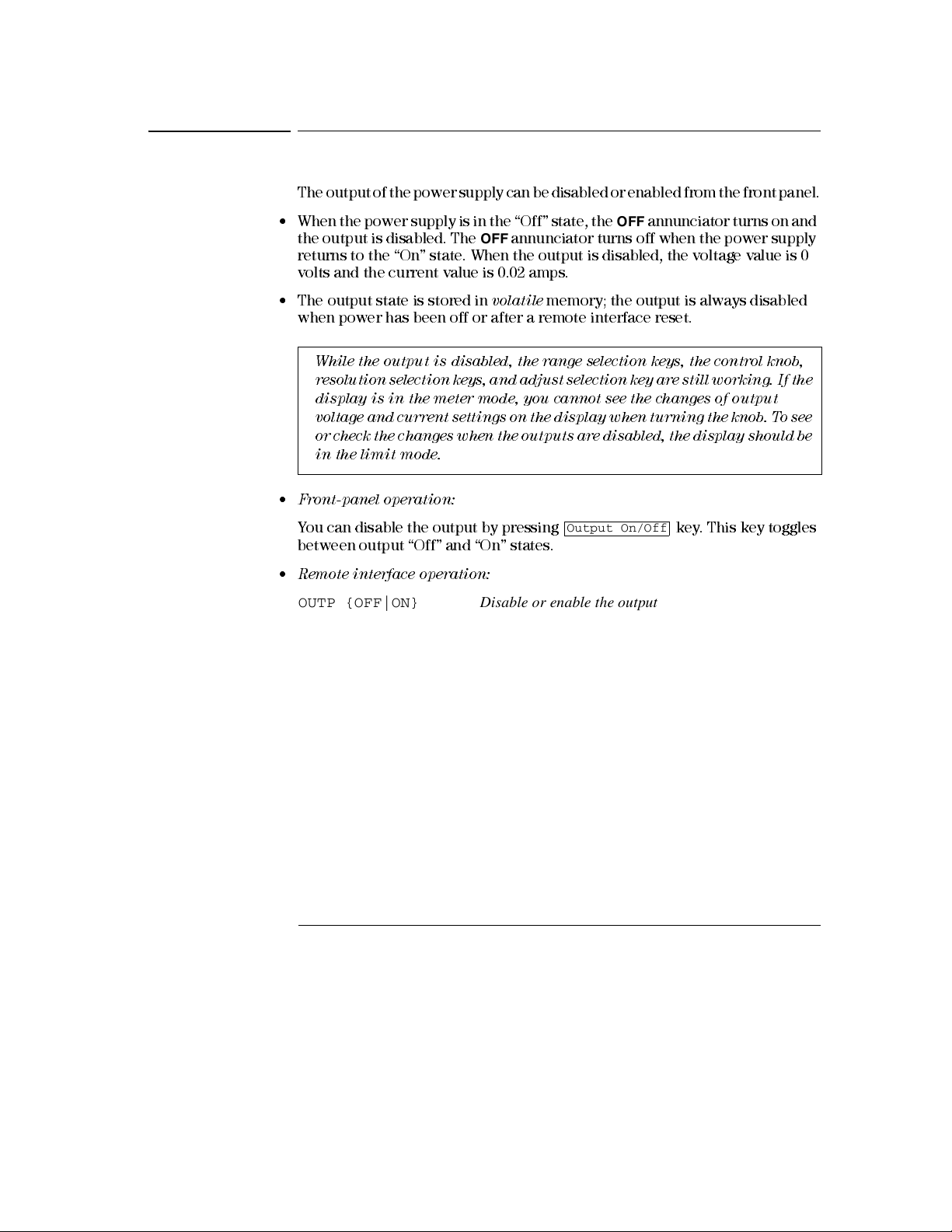
The output of the power supply can be disabled or enabled from the front panel.
• When the power supply is in the “Off” state, the
OFF
the output is disabled. The
returns to the “On” state. When the output is disabled, the voltage value is 0
volts and the current value is 0.02 amps.
• The output state is stored in
when power has been off or after a remote interface reset.
While the output is disa bled , the ra nge se le ction keys, the control knob,
resol utio n sele ctio n key s, and ad just select io n key a re sti ll wor king . If the
display is in the me ter mode , you ca nn ot see the ch anges of output
voltage and current settings on the display when turning the knob. To see
or ch eck th e cha ng es wh en t he out pu ts a re d isa bl ed, t he dis pla y sh ou ld b e
in the limit mode.
• Front-panel operation:
You can disable the output by pressing key. This key toggles
between output “Off” and “On” states.
• Remote inte rfac e oper ation:
OUTP {OFF|ON} Disable or enable the output
annunciator turns off when the power supply
volatile
memory; the output is always disabled
Output On/Off
OFF
annunciator turns on and
50
Page 53

Chapter 3 Front-Panel Operation
Disabling the Output Using an External Relay
Disabling the Output Using an External Relay
When the output of the E3632A is turned off, it is implemented by setting the
output to 0 volts and 0.02 amps. This gives a zero output voltage without
actually disconnecting the output. To disconnect the output an external relay
must be connected between the output and the load. A TTL signal of either low
true or high true is provided to control an external relay. This signal can only
be controlled with the remote command
output is available on the RS-232 connection pin 1 and pin 0.
When the
(4.5 V) and pin 9 is low (0.5 V). The levels are reversed when the
OUTPut:RELay
OUTPut:RELay
state is “OFF”.
state is “ON”, the TTL output of pin 1 is high
OUTPut:RELay {OFF|ON}
. The TTL
3
Note
Note
TTL output of pin 1 or pin 9 of the RS-232 connector is available only after
installin g two jumpe rs insi de the powe r su ppl y. See the Se rvic e Guide for
more information.
Do not use the RS-232 interface if you have configured the power supply to
output relay control signals. Internal components on the RS-232 circuitry
may be damaged .
Knob Locking
The knob locking function can be used to disable the knob, thereby preventing
any unwanted changes during an experiment, or when you leave the power
supply unattended. To disable the knob, press the resolution selection key until
the blinking digit disappears.
Notice that the knob and front panel keys are disabled when in the remote
interface mode.
51
Page 54

Chapter 3 Front-Panel Operation
System-Related Operations
System-Related Operations
This section gives information on topics such as self-test, error conditions, and
front-panel display control. This information is not directly related to setting
up the power supply but is an important part of operating the power supply.
Self-Test
A
power-on
This test assures you that the power supply is operational. This test does not
perform the extensive set of tests that are included as part of the complete self-
test described below. If the power-on self-test fails, the
turns on.
•A
complete
seconds to execute. If all tests pass, you can have a high confidence that the
power supply is operational.
self-test occurs automatically when you turn on the power supply.
ERROR
self-test performs a series of tests and takes approximately 2
annunciator
• If the
• Front-panel operation:
• Remote inte rfac e oper ation:
complete
If the self-test fails, “FAIL” is displayed and the
See the
Technologies for service.
The
panel keys except the key) and the power-line switch simultaneously
and then continuing to press the key for 5 seconds. The complete self-
test will be finished in 2 seconds.
Service Guide
complete
self-test is successful, “PASS” is displayed on the front panel.
ERROR
for instructions on returning the power supply to Agilent
self-test is enabled by pressing the the(actually any front
Error
Recall
annunciator turns on.
Recall
*TST?
Returns “0” if the complete self-test passes or “1” if it fails.
52
Page 55
Chapter 3 Front-Panel Operation
System-Related Operations
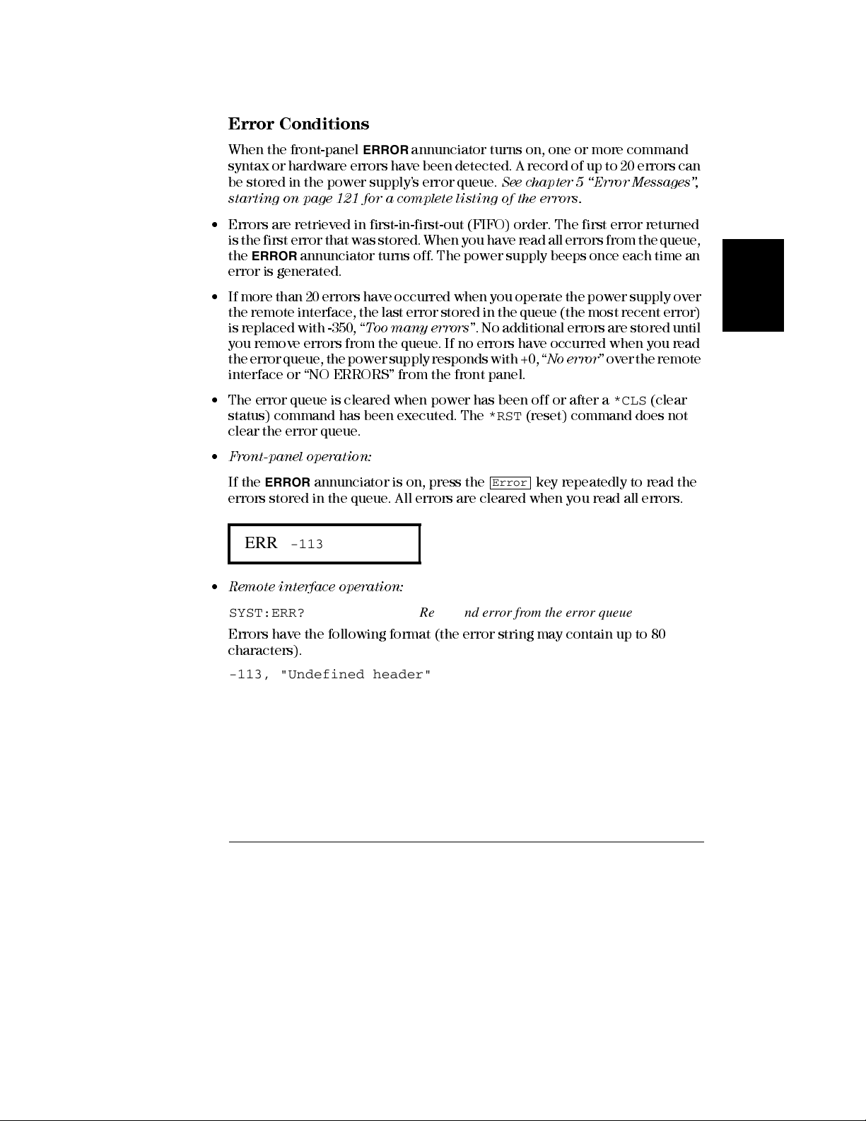
Error Conditions
When the front-panel
syntax or hardware errors have been detected. A record of up to 2 0 errors can
be stored in the power supply’s error queue.
starting on
• Errors are retrieved in first-in-first-out (FIFO) order. The first error returned
is the first error that was stored. When you have read all errors from the queue,
ERROR
the
error is generated.
• If more than 20 errors have occurred when you operate the power supply over
the remote interface, the last error stored in the queue (the most recent error)
is replaced with -350, “
you remove errors from the queue. If no errors have occurred when you read
the error queue, the power supply responds with +0, “
interface or “NO ERRORS” from the front panel.
• The error queue is cleared when power has been off or after a
status) command has been executed. The
clear the error queue.
• Front-panel operation:
If the
errors stored in the queue. All errors are cleared when you read all errors.
page 121 for a complete listing of the errors.
annunciator turns off. The power supply beeps once each time an
ERROR
annunciator is on, press the key repeatedly to read the
ERROR
annunciator turns on, one or more command
Too many erro rs
See chapter 5 “Error Messages”,
”. No additional errors are stored until
No error
*RST
(reset) command does not
Error
” over the remote
*CLS
(clear
ERR -113
3
• Remote inte rfac e oper ation:
SYST:ERR? Reads and error from the error queue
Errors have the following format (the error string may contain up to 80
characters).
-113, "Undefined header"
53
Page 56
Chapter 3 Front-Panel Operation
System-Related Operations
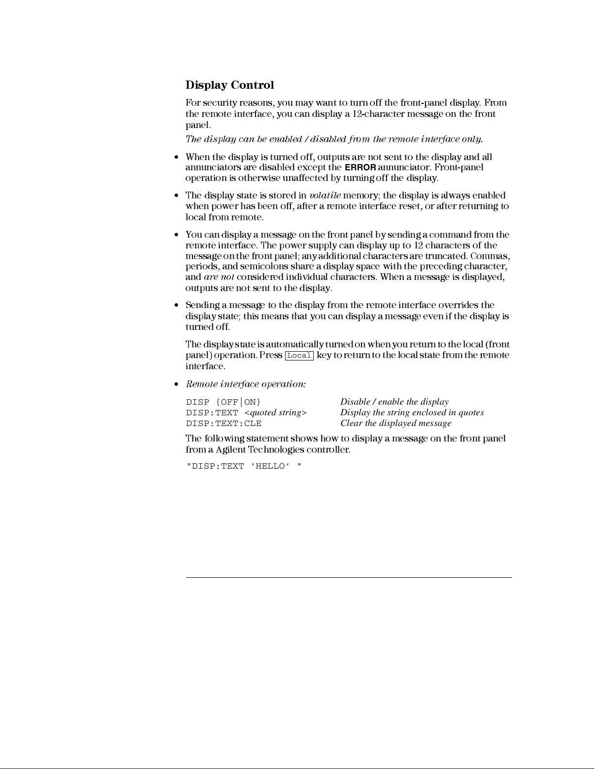
Display Control
For security reasons, you may want to turn off the front-panel display. From
the remote interface, you can display a 12-character message on the front
panel.
The display ca n be e na bled / disabl ed from the re m ote inte rface onl y.
• When the display is turned off, outputs are not sent to the display and all
annunciators are disabled except the
operation is otherwise unaffected by turning off the display.
ERROR
annunciator. Front-panel
• The display state is stored in
when power has been off, after a remote interface reset, or after returning to
local from remote.
• You can display a message on the front panel by sending a command from the
remote interface. The power supply can display up to 12 characters of the
message on the front panel; any additional characters are truncated. Commas,
periods, and semicolons share a display space with the preceding character,
and
are not
outputs are not sent to the display.
• Sending a message to the display from the remote interface overrides the
display state; this means that you can display a message even if the display is
turned off.
The display state is automatically turned on when you return to the local (front
panel) operation. Press
interface.
• Remote inte rfac e oper ation:
DISP {OFF|ON} Disable / enable the display
DISP:TEXT <quoted string> Display the string enclosed in quotes
DISP:TEXT:CLE Clear the displayed message
The following statement shows how to display a message on the front panel
from a Agilent Technologies controller.
"DISP:TEXT ‘HELLO’ "
considered individual characters. When a message is displayed,
volatile
Local
memory; the display is always enabled
key to return to the local state from the remote
54
Page 57

Chapter 3 Front-Panel Operation
System-Related Operations
Firmware Revision Query
The power supply has three microprocessor s for control of various internal
systems. You can query the power supply to determine which revision of
firmware is installed for each microprocessor.
You can query the firm w ar e re vision from the re m ote inte rfac e onl y.
• The power supply returns four fields separated by commas and the fourth field
is a revision code which contains three numbers. The first number is the
firmware revision number for the main processor; the second is for the input/
output processor; and the third is for the front-panel processor.
• Remote inte rfac e oper ation:
*IDN? Returns "HEWLETT-PACKARD,E3632A,0,X.X-X.X-X.X"
Be sure to dimension a string variable with at least 40 characters.
SCPI Language Version
The power supply compli es with the rules and regulations of the present
version of SCPI (Standard Commands for Programmable Instruments). You
can determine the SCPI version with which the power supply is in compliance
by sending a command from the remote interface.
You can query the SCPI version from the remote interface only.
• Remote inte rfac e oper ation:
SYST:VERS? Query the SCPI version
Returns a string in the form “YYYY .V” where the “Y’s” represent the year of the
version, and the “V” represents a version number for that year (for example,
1995.0).
3
55
Page 58

Chapter 3 Front-Panel Operation
Remote Interface Configuration
Remote Interface Configuration
Before you can operate the power supply over the remote interface, you must
configure the power supply for the remote interface. This section gives
information on configuring the remote interface. For additional information
on programming the power supply over the remote interface,
Interface Reference", starting on page 71 in chapter 4.
Remote Interface Selection
The power supply is shipped with both an GPIB (IEEE-488) interface and an
RS-232 interface on the rear panel. Only one interface can be enabled at a time.
The
GPIB interfac e
factory.
The remote interface can be selected from the front-panel only.
• The interface selection is stored in
change when power has been off or after a remote interface reset.
• If you select the GPIB interface, you must select a unique address for the
power supply. The current address is displayed momentarily on the front
panel when you turn on the power supply.
• Your GPIB bus controller has its own address. Be sure to avoid using the
bus controller’s address for any instrument on the interface bus. Agilent
Technologies controll ers generally use address “21”.
• If you enable the RS-232 interface, you must select the baud rate and parity
to be used. “RS-232” is displayed momentarily on the front panel when you
turn on the power supply if you have selected this interface.
is selected when the power supply is shipped from the
non-volatile
memory, and
1
See "Remote
does not
2
1
Refer to "GPIB Interface Configuration" starting on page 61 for more information
on connecting the power supply to a computer over the GPIB interface.
2
Refer to "RS-232 Interface Configuration" starting on page 62 for more information
on connecting the power supply to a computer over the RS-232 interface.
56
Page 59
Chapter 3 Front-Panel Operation
Remote Interface Configuration
GPIB Address
Each device on the GPIB (IEEE-488) interface must have a unique address.
You can set the power supply’s address to any value between 0 and 30. The
current address is displayed momentarily on the front panel when you turn on
the power supply . The address is set to “05” when the power supply is shipped
from the factory.
The GPIB address can be set from the front-panel only.
• The address is stored in
power has been off or after a remote interface reset.
• Your GPIB bus controller has its own address. Be sure to avoid the bus
controller’s address for any instrument on the interface bus. Agilent
Technologies controll ers generally use address “21”.
non-volatile
memory, and
does not
change when
Baud Rate Selection (RS-232)
You can select one of six baud rates for RS-232 operation. The rate is set to
9600 baud
The baud rate can be set from the front-panel only.
• Select one of the following: 300, 600, 1200, 2400, 4800,
setting is 9600 baud.
• The baud rate selection is stored in
change when power has been off or after a remote interface reset.
when the power supply is shipped from the factory.
9600
baud.
non-volatile
memory, and
The f actory
does not
3
Parity Selection (RS-232)
Y ou can select the parity for RS-232 operation. The power supply is configured
for
no parity and 8 data bits
The parity can be set from the front-panel only.
• Select one of the following:
(
7 data bits
of data bits.
• The parity selection is stored in
when power has been off or after a remote interface reset.
). When you set the parity, you are indirectly setting the number
when shipped from the factory.
None
(
8 data bits
non-volatile
), Even (
memor y , a n d
7 data bits
does not
), or Odd
change
57
Page 60

I/O Config
I/O Config
Chapter 3 Front-Panel Operation
Remote Interface Configuration
To Set the GPIB Address
To configure the power supply for the GPIB interface, proceed as follows:
1
Turn on the remote configuration mode.
GPIB / 488
Y ou will see the above message on the front-panel display if the power supply
has not been changed from the factory setting. If “RS-232” appears, choose
“GPIB / 488” by turning the knob to the right.
2
Move to the GPIB address setting mode.
ADDR 05
The address is set to “05” when the power supply is shipped from the factory.
Notice that a different GPIB address may appear if the power supply has been
changed from the factory setting.
I/O Config
Note
3
Turn the knob to change the GPIB address.
The displayed address is changed when turning the knob to the right or left.
4
Save the change and turn off the I/O configuration mode.
CHANGE SAVED
The address is stored in
power has been off or after a remote interface reset. The power supply displays
a message to show that the change is now in effect. If the GPIB address is not
changed, “NO CHANGE” will be displayed for one second.
To exit the I/O configuration mode without any further changes, press the
“I/O Config” key until the “NO CHANGE” message is displayed.
58
non-volatile
memory, and
does not
change when
Page 61

I/O Config
I/O Config
Chapter 3 Front-Panel Operation
Remote Interface Configuration
To Set the Baud Rate and Parity (RS-232)
To configure the power supply for the RS-232 interface, proceed as follows:
1
Turn on the remote configuration mode.
GPIB / 488
Y ou will see the above message on the display if the power supply has not been
changed from the factory setting.
Notice that if you changed the rem ote inte rfac e se le ction to RS-232 before,
“RS-232” me ss age wil l be dis pla yed.
2
Choose the RS-232 interface.
RS-232
You can choose the RS-232 interface by turning the knob to the left.
3
Move to the RS-232 interface setting mode and select the baud rate.
3
I/O Config
9600 BAUD
The rate is set to
Choose from one of the following by turning the knob to the right or left: 300,
600, 1200, 2400, 4800, or
4
Save the change and choose the parity.
9600
baud when the power supply is shipped from the factory.
9600
baud.
NONE 8 BITS
The power supply is configured for 8 data bits with no parity when shipped
from the factory. Choose from one of the following by turning the knob to the
right or left:
are indirectly setting the number of the data bits.
None 8 Bits
, Odd 7 Bits, or Even 7 Bits. When you set parity, you
59
Page 62

Chapter 3 Front-Panel Operation
Remote Interface Configuration
I/O Config
Note
5
Save the change and turn off the I/O configuration mode.
CHANGE SAVED
The RS-232 baud rate and parity selections are stored in
and
does not
The power supply displays a message to show that the change is now in effect.
If the baud rate and the parity are not changed, “NO CHANGE” will be displayed
for one second.
To exit the I/O configuration mode without any further changes, press the
“I/O Config” key until the “NO CHANGE” message is displayed.
change when power has been off or after a remote interface reset.
non-volatile
memo ry,
60
Page 63

Chapter 3 Front-Panel Operation
GPIB Interface Configuration
GPIB Interface Configuration
The GPIB connector on the rear panel connects your power supply to the
computer and other GPIB devices. Chapter 1 lists the cables that are available
from Agilent Technologies. An GPIB system can be connected together in any
configuration (star, linear, or both) as long as the following rules are observed:
• The total number of devices including the computer is no more than 15.
• The total length of all the cables used is no more than 2 meter times the
number of devices connected together, up to a maximum of 20 meters.
Note
IEEE-488 states that you should ex er cis e ca ution if your in dividu al ca ble
lengths exce ed 4 m ete rs .
Do not stack more than three connector blocks together on any GPIB
connector. Make sure that all connectors are fully seated and that the lock
screws are firmly finger tightened.
3
61
Page 64
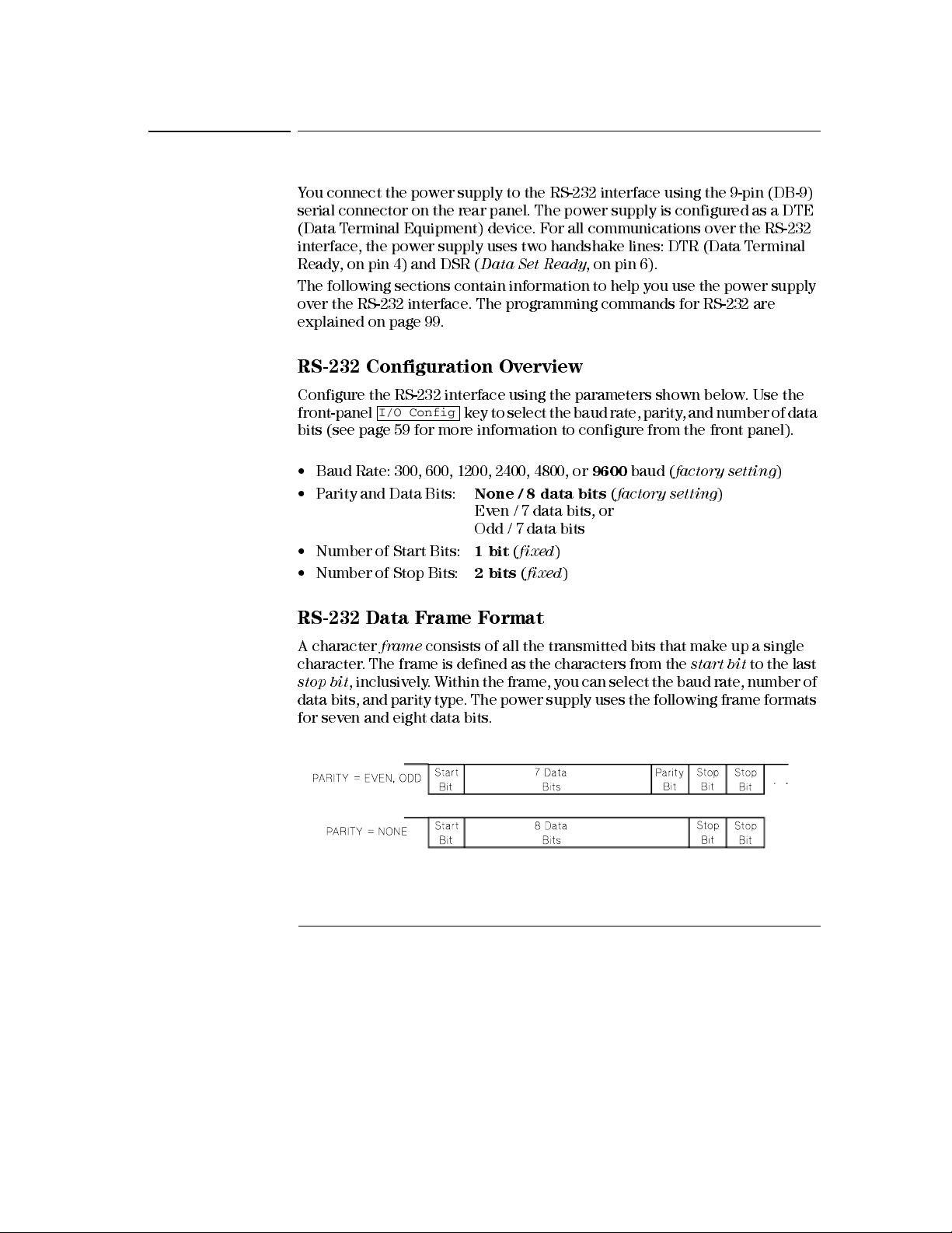
Chapter 3 Front-Panel Operation
RS-232 Interface Configuration
RS-232 Interface Configuration
You connect the power supply to the RS-232 interface using the 9-pin (DB-9)
serial connector on the rear panel. The power supply is configured as a DTE
(Data Terminal Equipment) device. For all communications over the RS-232
interface, the power supply uses two handshake lines: DTR (Data Terminal
Ready, on pin 4) and DSR (
The following sections contain information to help you use the power supply
over the RS-232 interface. The programming commands for RS-232 are
explained on
page 99.
RS-232 Configuration Overview
Configure the RS-232 interface using the parameters shown below. Use the
front-panel
bits (see page 59 for more information to configure from the front panel).
I/O Config
Data Set Ready
key to select the baud rate, parity, and number of data
, on pin 6).
• Baud Rate: 300, 600, 1200, 2400, 4800, or
• Parity and Data Bits:
• Number of Start Bits:
• Number of Stop Bits:
None / 8 data bits (factory setting
Even / 7 data bits, or
Odd / 7 data bits
1 bit (fixed
2 bits (fixed
9600
baud (
)
)
factory setting
)
)
RS-232 Data Frame Format
A character
character. The frame is defined as the characters from the
stop bit
data bits, and parity type. The power supply uses the following frame formats
for seven and eight data bits.
frame
consists of all the transmitted bits that make up a single
start bit
, inclusively. Within the frame, you can select the baud rate, number of
to the last
62
Page 65

Chapter 3 Front-Panel Operation
RS-232 Interface Configuration
Connection to a Computer or Terminal
To connect the power supply to a computer or terminal, you must have the
proper interface cable. Most computers and terminals are DTE (
Equipment
) devices. Since the power supply is also a DTE device, you must
use a DTE-to-DTE interface cable. These cables are also called
modem-eliminator
, or
crossover cabl es
.
The interface cable must also have the proper connector on each end and the
internal wiring must be correct. Connectors typically have 9 pins (DB-9
connector) or 25 pins (DB-25 connector) with a “male” or “female” pin
configuration. A male connector has pins inside the connector shell and a
female connector has holes inside the connector shell.
If you cannot find the correct cable for your configuration, you may have to
use a
wiring adapter
. If you are using a DTE-to-DTE cable, make sure the
adapter is a “straight-through” type. Typical adapters include gender changers,
null-m odem adapters, and DB- 9 to DB-25 adapters.
The cable and adap ter diagr am s sh own bel ow can be use d to connec t the
power supply to most computers or terminals
. If your configuration is
different than those described, order the Agilent 34399A
contains adapters for connection to other computers, terminals, and modems.
Instructions and pin diagrams are includ ed with the adapter kit.
Data Terminal
null-modem,
Adapter Kit
. This k it
3
DB-9 Serial Connection
If your computer or terminal has a 9-pin serial port
with a male connector, use the null-modem cable included with the
34398A Cable Kit.
cable pin diagram is shown below
Instrument
This cable has a 9-pin female connector on each end. The
.
5182-4794
DCD
RX
TX
DTR
GND
DSR
RTS
CTS
RI
DB9
Male
1
2
3
4
5
6
7
8
9
DB9
Female
Cable
DB9
Female
PC
1
2
3
4
5
6
7
8
9
DCD
RX
TX
DTR
GND
DSR
RTS
CTS
RI
DB9
Male
Agilent
63
Page 66
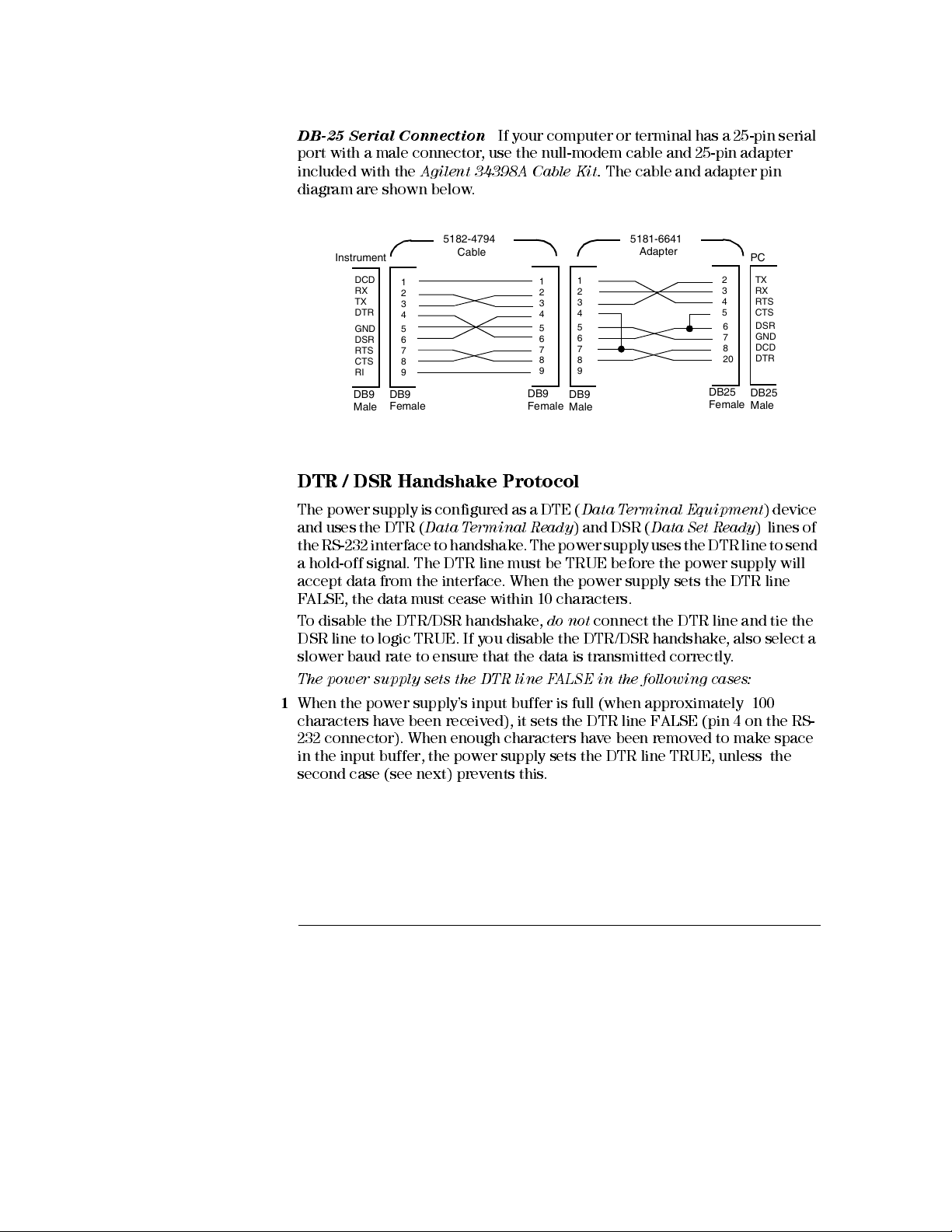
Chapter 3 Front-Panel Operation
RS-232 Interface Configuration
DB-25 Serial Connection
If your computer or terminal has a 25-pin serial
port with a male connector, use the null-modem cable and 25-pin adapter
included with the
Agilent 34398A Cable Kit.
The cable and adapter pin
diagram are shown below.
5182-4794
Instrument PC
DCD
1
RX
2
TX
3
DTR
4
5
GND
6
DSR
7
RTS
8
CTS
9
RI
DB9
DB9
Female
Male
Cable
1
2
3
4
5
6
7
8
9
DB9
Femal e
1
2
3
4
5
6
7
8
9
DB9
Male
5181-6641
Adapter
2
3
4
5
6
7
8
20
DB25
Female
TX
RX
RTS
CTS
DSR
GND
DCD
DTR
DB25
Male
DTR / DSR Handshake Protocol
The power supply is configured as a DTE (
and uses the DTR (
Data Terminal Ready
the RS-232 interface to handshake. The power supply uses the DTR line to send
a hold-off signal. The DTR line must be TRUE before the power supply will
accept data from the interface. When the power supply sets the DTR line
FALSE, the data must cease within 10 characters.
To disable the DTR/DSR handshake,
DSR line to logic TRUE. If you disable the DTR/DSR handshake, also select a
slower baud rate to ensure that the data is transmitted correctly.
The power supp ly se ts the DTR li ne FALSE in the following case s:
1
When the power supply’s input buffer is full (when approximately 100
characters have been received), it sets the DTR line FAL SE (pi n 4 on the RS-
232 connector). When enough characters have been removed to make space
in the input buffer, the power supply sets the DTR line TRUE, unless the
second case (see next) prevents this.
Data Terminal Equipment
) and DSR (
do not
connect the DTR line and tie the
Data Set Ready
) device
) lines of
64
Page 67
Chapter 3 Front-Panel Operation
RS-232 Interface Configuration
2
When the power supply wants to “talk” over the interface (which means that
it has processed a query) and has received a
it will set the DTR line FALSE. This implies that once a query has been sent to
the power supply, the bus controller should read the response before
attempting to send more data. It also means that a
the command string. After the response has been output, the power supply sets
the DTR line TRUE again, unl ess the first case (see above) prevents this.
The power supply monitors the DSR line to determine when the bus controller
is ready to accept data over the interface. The power supply monitors the DSR
line (pin 6 on the RS-232 connector) before each character is sent. The output
is suspended if the DSR line is FALSE. When the DSR line goes TRUE,
transmission will resume.
The power supply holds the DTR line FALSE while output is suspended. A form
of interface
to allow the power supply to complete the transmission. You can break the
interface deadlock by sending the
operation in progress and discards pending output (this is equivalent to the
IEEE- 488 device clear action).
deadlock
exists until the bus controller asserts the DSR line TRUE
<Ctrl-C>
<new line>
character, which clears the
message terminator,
<new line>
must terminate
3
For the <Ctrl-C> character to be recognized reliably by the power supply
while it holds DTR FALSE, the bus controll er m us t first set DSR FALSE.
RS-232 Troubleshooting
Here are a few things to check if you are having problems communicating over
the RS-232 interface. If you need additional help, refer to the documentation
that came with your computer.
• Verify that the power supply and your computer are configured for the same
baud rate, parity, and number of data bits. Make sure that your computer is
set up for
supply).
• Make sure to execute the
supply in the remote mode.
• Verify that you have connected the correct interface cable and adapters.
Even if the cable has the proper connectors for your system, the internal
wiring may be incorrect. The
be used to connect the power supply to most computers or terminals.
• Verify that you have connected the interface cable to the correct serial port
on your computer (COM1, COM2, etc).
1 start
bit and
2 stop bits
SYSTem:REMote
(these values are fixed on the power
command to place the power
Agilen t Tec hnol ogies 3439 8A C able Kit
can
65
Page 68

Chapter 3 Front-Panel Operation
Calibration Overview
Calibration Overview
This section gives an overview of the calibration features of the power supply.
For more detailed discussion of the calibration procedures, see the
Guide
.
Calibration Security
This feature allows you to enter a security code to prevent accidental or
unauthorized calibrations of the power supply. When you first receive your
power supply, it is secured. Before you can calibrate the power supply, you
must unsecure it by entering the correct security code.
•
The security code
from the factory
does not
• To secure the power supply from the
may contain up to 12 alphanumeric characters as shown below. The first
character
numbers. You do not have to use all 12 characters but the first character
must always be a
change when power has been off or after a remote interface reset.
must be a letter
is set to “HP003632”
. The security code is stored in
, but the remaining characters can be letters or
letter
.
when the power supply is shipped
remote in ter face
non-volatile
, the security code
Service
memory, and
A _ _ _ _ _ _ _ _ _ _ _ (
• To secure the power supply from the
unsecured from the front panel, use the eight-character format shown
below. The first two characters must be “H P” and the remaining characters
must be numbers. Only the last six characters are recognized from the front
panel, but all eight characters are required.
from the front panel, omit the “H P” and enter the remaining numbers as
shown on the following pages .
H P _ _ _ _ _ _ (
If you forget your securi ty code, you can disabl e the se cu rity featu re by
adding a jumper inside the power supply, and then entering a new code.
See the Servic e Gui de for m ore in form ation.
66
8 characters
12 characters
remote in ter face
To unsecure the power supply
)
)
so that it can be
Page 69
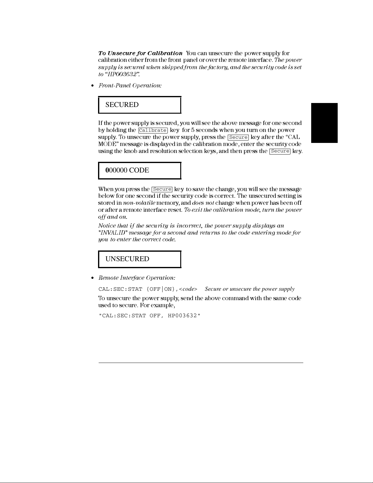
Chapter 3 Front-Panel Operation
Calibration Overview
To Unsecure for Calibration
calibration either from the front panel or over the remote interface.
supply is secured when shipped from the factory, and the security code is set
to “HP003632”.
• Front-Panel Operation:
You can unsecure the power supply for
The p owe r
SECURED
If the power supply is secured, you will see the above message for one second
by holding the
supply. To unsecure the power supply, press the key after the “CAL
MODE” message is displayed in the calibration mode, enter the security code
using the knob and resolution selection keys, and then press the
Calibrate
key for 5 seconds when you turn on the power
Secure
Secure
000000 CODE
When you press the key to save the change, you will see the message
below for one second if the security code is correct. The unsecured setting is
stored in
or after a remote interface reset.
off and on.
Notice that if the security is incor re ct, the power suppl y dis plays an
"INVALID" me ss age for a sec ond and retu rns to the code ente rin g mode for
you to enter the correct code.
non-volatile
Secure
memor y , and
does not
T o e xit t he c ali bra ti on mod e, t urn th e po we r
change when power has been off
3
key.
UNSECURED
• Remote Inte rfac e Ope ration :
CAL:SEC:STAT {OFF|ON},<code> Secure or unsecure the power supply
To unsecure the power supply, send the above command with the same code
used to secure. For example,
"CAL:SEC:STAT OFF, HP003632"
67
Page 70
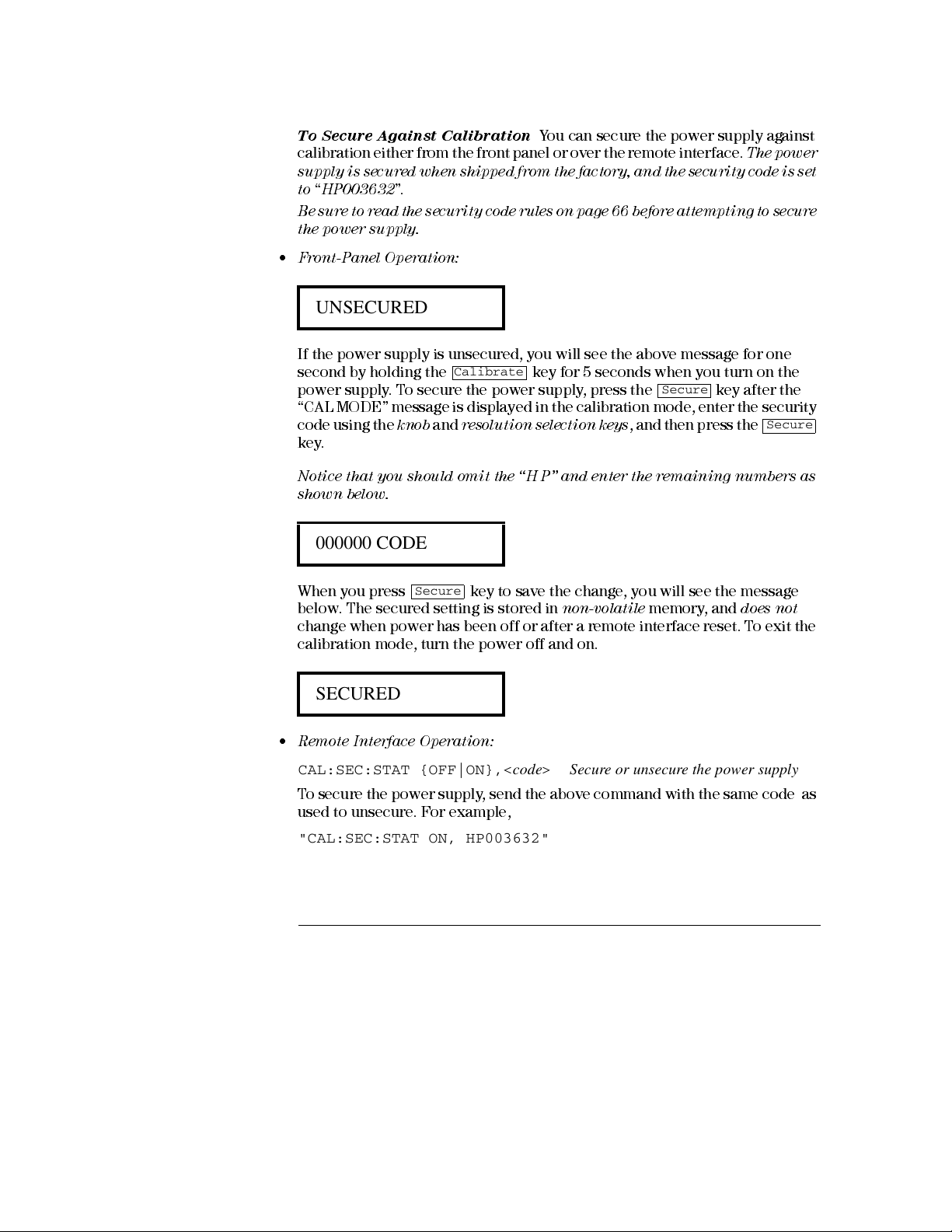
Chapter 3 Front-Panel Operation
Calibration Overview
To Secure Against Calibration
calibration either from the front panel or over the remote interface.
supply is secured when shipped from the factory, and the security code is set
to “HP003632
Be sure to rea d th e securi ty co de rul es on p age 6 6 bef ore a ttemp tin g to secure
the power suppl y.
• Front-Panel Operation:
”.
You can secure the power supply against
The po wer
UNSECURED
If the power supply is unsecured, you will see the above message for one
second by holding the
power supply. To secure the power supply, press the key after the
“CAL MODE” message is displayed in the calibration mode, enter the security
code using the
key.
Notice that you should omit the “H P” and enter the remaining numbers as
shown below.
knob
Calibrate
and
resolution selection keys
key for 5 seconds when you turn on the
Secure
, and then press the
Secure
000000 CODE
When you press key to save the change, you will see the message
below. The secured setting is stored in
change when power has been off or after a remote interface reset. To exit the
calibration mode, turn the power off and on.
Secure
non-volatile
memory, and
does not
SECURED
• Remote Inte rfac e Ope ration :
CAL:SEC:STAT {OFF|ON},<code> Secure or unsecure the power supply
T o secure the power supply, send the above command with the same code as
used to unsecure. For example,
"CAL:SEC:STAT ON, HP003632"
68
Page 71
Chapter 3 Front-Panel Operation
Calibration Overview
To Change the Security Code
unsecure the power supply, and then enter a new code.
Be sure to rea d th e securi ty co de rul es on p age 6 6 bef ore a ttemp tin g to secure
the power suppl y.
• Front-Panel Operation:
To change the security code, first make sure that the power supply is
unsecured
the calibration mode, enter the new security code using the knob and
resolution selection keys, then press
Changing the code from the front panel also changes the code required from
the remote inte rfac e.
• Remote Inte rfac e Ope ration :
CAL:SEC:CODE <new code>Change the security code
To change the security code, first unsecure the power supply using the old
security code. Then, enter the new code. For example,
"CAL:SEC:STAT OFF, HP003632*" Unsecure with old code
"CAL:SEC:CODE ZZ001443" Enter new code
"CAL:SEC:STAT ON, ZZ00143" Secure with new code
. Press
Secure
To change the security code, you must first
key after the “CAL MODE” message is displayed in
Secure
key.
3
69
Page 72
Chapter 3 Front-Panel Operation
Calibration Overview
Calibration Count
You can determine the number of times that your power supply has been
calibrated. Your power supply was calibrated before it left the factory. When
you receive your power supply, read the count to determine its initial value.
The calibration count feature can be performed from the remote interface
only.
• The calibration count is stored in
when power has been off or after a remote interface reset.
• The calibration count increments up to a maximum of 32,767 after which it
wraps-around to 0. Since the value increments by one for each calibration
point, a complete calibration wil l incr ease the value by 5 counts.
• Remote Inte rfac e Ope ration :
CAL:COUN? Query the number of times of calibration
non-volatile
memory, and
does not
change
Calibration Message
Y ou can use the calibration message feature to record calibration information
about your power supply. For example, you can store such information as the
last calibration date, the next calibration due date, the power supply’s serial
number, or even the name and phone number of the person to contact for a
new calibration.
You can recor d and re ad inform a tion in the cal ibr ation m es sage from the
remote inte rfac e only.
• The power supply should be unsecured before sending a calibration
message.
• The calibration message may contain up to 40 characters.
• The calibration message is stored in
change when power has been off or after a remote interface reset.
non-volatile
memory, and
does not
• Remote Inte rfac e Ope ration :
CAL:STR <quoted string> Store the cal message
The following command string shows how to store a calibration message.
"CAL:STR ‘CAL 05-1-97’ "
70
Page 73

Chapter 3 Front-Panel Operation
Calibration Overview
3
71
Page 74

4
Remote Interface Reference
Page 75
SCPI
SCPI
Remote Interface Reference
• SCPI Command Summary, page 73
• Simplified Programming Overview, page 78
• Using the APPLy Comm and, page 81
• Output Setting and Operation Commands, page 82
• Triggering Commands, page 89
• System-Related Commands, page 92
• Calibration C om mands , page 96
• RS-232 Interface Commands, page 99
• The SCPI Status Registers, page 100
• Status Reporting Commands, page 108
• An Introduction to the SCPI Language, page 111
• Halting an Output in Progress, page 116
• SCPI Conformance Information, page 117
• IEEE-488 Conformance Information, page 120
SCPI
If you are a first-time us er of the SCPI la nguage , you m ay wan t to refer to
these section s to becom e fam il iar wi th the langu age before attem pting to
program the power supply.
72
Page 76

Chapter 4 Remote Interface Reference
SCPI Command Summary
SCPI Command Summary
SCPI
This section summarizes the SCPI (
Instruments
remote interface. Refer to the later sections in this chapter for more complete
details on each command.
Throughout this manual, the following conventions are used for SCPI
command syntax.
• Square brackets ([ ]) indicate optional keywords or parameters.
• Braces ({ }) enclose parameters within a command string.
• Triangle brackets (< >) indicate that you must substitute a value or a code
for the enclosed parameter.
• A vertical bar ( | ) separates one of two or more alternative parameters.
First-time SCPI users, see page 111.
) commands available to program the power supply over the
Standard Commands for Programmable
4
73
Page 77

Chapter 4 Remote Interface Reference
SCPI Command Summary
Output Setting and Measurement Commands
APPLy {<voltage>|DEF|MIN|MAX}[,{<current>|DEF|MIN|MAX}]
APPLy?
[SOURce:]
CURRent[:LEVel][:IMMediate][:AMPLitude]{<current>|MIN|MAX|UP|DOWN}
CURRent[:LEVel][:IMMediate][:AMPLitude]? [MIN|MAX]
CURRent[:LEVel][:IMMediate]:STEP[:INCRement]
{<numeric value> |DEFault}
CURRent[:LEVel][:IMMediate]:STEP[:INCRement]? {DEFault}
CURRent[:LEVel]:TRIGgered[:AMPLitude] {<current>|MIN|MAX}
CURRent[:LEVel]:TRIGgered[:AMPLitude]? [MIN|MAX]
CURRent:PROTection[:LEVel] {<current>|MIN|MAX}
CURRent:PROTection[:LEVel]? {MIN|MAX}
CURRent:PROTection:STATe {0|1|OFF|ON}
CURRent:PROTection:STATe?
CURRent:PROTection:TRIPped?
CURRent:PROTection:CLEar
VOLTage[:LEVel][:IMMediate][:AMPLitude]{<voltage>|MIN|MAX|UP|DOWN}
VOLTage[:LEVel][:IMMediate][:AMPLitude]? [MIN|MAX]
VOLTage[:LEVel][:IMMediate]:STEP[:INCRement]
{<numeric value>|DEFault}
VOLTage[:LEVel][:IMMediate]:STEP[:INCRement]? {DEFault}
VOLTage[:LEVel]:TRIGgered[:AMPLitude] {<voltage>|MIN|MAX}
VOLTage[:LEVel]:TRIGgered[:AMPLitude]? [MIN|MAX]
VOLTage:PROTection[:LEVel] {<voltage>|MIN|MAX}
VOLTage:PROTection[:LEVel]? {MIN|MAX}
VOLTage:PROTection:STATe {0|1|OFF|ON}
VOLTage:PROTection:STATe?
VOLTage:PROTection:TRIPped?
VOLTage:PROTection:CLEar
VOLTage:RANGe {P15V|P30V|LOW|HIGH}
VOLTage:RANGe?
MEASure
:CURRent[:DC]?
[:VOLTage][:DC]?
74
Page 78

Chapter 4 Remote Interface Reference
SCPI Command Summary
Triggering Commands
INITiate[:IMMediate]
TRIGger[:SEQuence]
:DELay {<seconds>|MIN|MAX}
:DELay?
:SOURce {BUS|IMM}
:SOURce?
*TRG
System-Related Commands
DISPlay[:WINDow]
[:STATe] {OFF|ON}
[:STATe]?
:TEXT[:DATA] <quoted string>
:TEXT[:DATA]?
:TEXT:CLEar
SYSTem
:BEEPer[:IMMediate]
:ERRor?
:VERSion?
OUTPut
:RELay[:STATe] {OFF|ON}
:RELay[:STATe]?
[:STATe] {OFF|ON}
[:STATe]?
4
*IDN?
*RST
*TST?
*SAV {1|2|3}
*RCL {1|2|3}
75
Page 79

Chapter 4 Remote Interface Reference
SCPI Command Summary
Calibration Commands
CALibration
:COUNt?
:CURRent[:DATA] <numeric value>
:CURRent:LEVel {MIN|MID|MAX}
:CURRent:PROTection
:DAC:ERRor
:SECure:CODE <new code>
:SECure:STATe {OFF|ON},<code>
:SECure:STATe?
:STRing <quoted string>
:STRing?
:VOLTage[:DATA] <numeric value>
:VOLTage:LEVel {MIN|MID|MAX}
:VOLTage:PROTection
Status Reporting Commands
STATus:QUEStionable
:CONDition?
[:EVENt]?
:ENABle <enable value>
:ENABle?
SYSTem:ERRor?
*CLS
*ESE <enable value>
*ESE?
*ESR?
*OPC
*OPC?
*PSC {0|1}
*PSC?
*SRE <enable value>
*SRE?
*STB?
*WAI
76
Page 80

Chapter 4 Remote Interface Reference
SCPI Command Summary
RS-232 Interface Commands
SYSTem
:LOCal
:REMote
:RWLock
IEEE-488.2 Common Commands
*CLS
*ESE <enable value>
*ESE?
*ESR?
*IDN?
*OPC
*OPC?
*PSC {0|1}
*PSC?
*RST
*SAV {1|2|3}
*RCL {1|2|3}
*SRE <enable value>
*SRE?
*STB?
*TRG
*TST?
*WAI
4
77
Page 81
Chapter 4 Remote Interface Reference
Simplified Programming Overview
Simplified Programming Overview
This section gives an overview of the basic techniques used to program the
power supply over the remote interface. This section is only an overview and
does not give all of the details you will need to write your own application
programs. Refer to the remainder of this chapter and also chapter 6,
“Application Programs ”, for mor e details and examples . Al so refer to the
programming reference manual that came with your computer for details on
outputting command strings and entering data.
Using the APPLy Command
The
APPLy
the power supply over the remote interface. For example, the following
statement executed from your computer will set the power supply to an output
of 3 V rated at 1 A:
‘‘APPL 3.0, 1.0’’
command provides the most straightforward method to program
Using the Low-Level Commands
Although the
program the power supply, the low-level commands give you more flexibility
to change individual parameters. For example, the following statements
executed from your computer will set the power supply to an output of 3 V
rated at 1 A:
‘‘VOLT 3.0’’ Set output voltage to 3.0 V
‘‘CURR 1.0’’ Set output current to 1.0 A
78
APPLy
command provides the most straightforward method to
Page 82

Chapter 4 Remote Interface Reference
Simplified Programming Overview
Reading a Query Response
Only the query commands (commands that end with “ ? ” ) will instruct the
power supply to send a response message. Queries return either output values
or internal instrument settings . For exampl e, the follow ing statements
executed from your computer will read the power supply’s error queue and
print the most recent error:
dimension statement Dimension string array (80 elements)
‘‘SYST:ERR?’’ Read error queue
bus enter statement Enter error string into computer
print statement Print error string
Selecting a Trigger Source
The power supply will accept a ‘‘bus’’ (software) trigger or an immediate
internal trigger as a trigger source. By default, the ‘‘BUS’’ trigger source is
selected. If you want the power supply to use an immediate internal trigger,
you must select ‘‘IMMediate’’. For example, the following statements executed
from your computer will set to an output of 3 V/1 A immediately:
‘‘VOLT:TRIG 3.0’’ Set the triggered voltage level to 3.0 V
‘‘CURR:TRIG 1.0’’ Set the triggered current level to 1.0 A
‘‘TRIG:SOUR IMM’’ Select the immediate trigger as a source
‘‘INIT’’ Cause the trigger system to initiate
4
79
Page 83
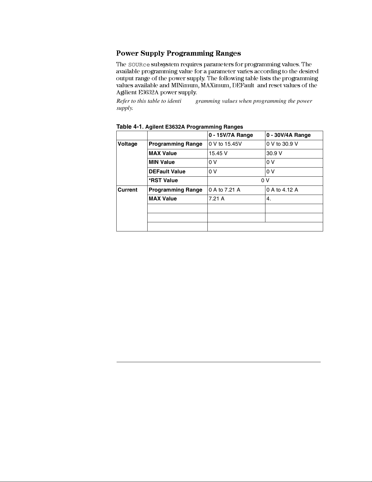
Chapter 4 Remote Interface Reference
Simplified Programming Overview
Power Supply Programming Ranges
The
SOURce
available programming value for a parameter varies according to the desired
output range of the power supply. The following table lists the programming
values available and MINimum , MA X im um , DEF ault and reset values of the
Agilient E3632A power sup ply.
Refer to this table to identify programming values when programming the power
supply.
Table 4-1. Agilent E3632A Programming Ranges
Voltage Programming Range 0 V to 15.45V 0 V to 30.9 V
Current Programming Range 0 A to 7.21 A 0 A to 4.12 A
subsystem requires parameters for programming values. The
0 - 15V/7A Range 0 - 30V/4A Range
MAX Value 15.45 V 30.9 V
MIN Value 0 V 0 V
DEFault Value 0 V 0 V
*RST Value 0 V
MAX Value 7.21 A 4.12 A
MIN Value 0 A 0 A
DEFault Value 7 A 4 A
*RST 7 A
80
Page 84

Chapter 4 Remote Interface Reference
Using the APPLy Command
Using the APPLy Command
The
APPLy
command provides the most straightforward method to program
the power supply over the remote interface. You can select the output voltage
and current in one command.
APPLy {<voltage>| DEF | MIN | MAX}[,{<current>| DEF | MIN | MAX}]
This command is combination of
as the newly programmed values are within the presently selected range, the
output voltage and current are changed as soon as the command is executed.
The
APPLy
command changes the power supply’s output to the newly
programmed values only if the programmed values are valid within the
presently selected range. An execution error will occur if the programmed
values are not valid within the selected range.
You can substitute ‘‘MINimum’’, ‘‘MAXimum’’, or ‘‘DEFault’’ in place of a
specific value for the
values of ‘‘0’’ volts and ‘‘0’’ amps. MAX selects the highest values allow ed for
the selected range.
The
default
of the presently selected range.
If you specify only one parameter of the
regards it as voltage setting value.
values of voltage and current are ‘‘0’’ volts and ‘‘7’’ amps regardless
voltage
and
See
VOLTage
current
and
CURRent
parameters. MIN selects the lowest
Table 4-1 for details of param e ter s.
APPLy
command, the power supply
commands. As long
4
APPLy?
This command queries the power supply’s present
values and returns a quoted string. The voltage and current are returned in
sequence as shown in the sample string below (the quotation marks are
returned as part of the string).
"15.00000,4.00000"
In the above string, the first number 15.00000 is the voltage setting value and
the second number 4.00000 is the current setting value.
voltage
and
current
setting
81
Page 85

Chapter 4 Remote Interface Reference
Output Setting and Operation Commands
Output Setting and Operation Commands
This section describes low-level commands used to program the power supply.
Although the
program the power supply, the low-level output setting comm ands give you
more flexibility to change the individual parameters.
CURRent{<current>|MINimum | MAXimum|UP|DOWN}
This command programs the immediate current level of the power supply. The
immediate level is the current value of the output terminals.
The
CURRent
programmed value regardless of the output range presently selected.
You can substitute ‘‘MINimum’’ or ‘‘MAXimum’’ in place of a specific value for
the current parameter. MIN selects the lowest current values of ‘‘0’’ amps. MAX
selects the highest current values allowed for the selected range.
This command also increases or decreases the immediate current level using
the ‘‘UP’’ or ‘‘DOWN’’ parameter by a predetermined amount. The command
CURRent:STEP
increment setting will cause an execution error -222 (Data out of range) when
the maximum or the minimum rated current is exceeded.
APPLy
command provides the most straightforward method to
command changes the output of the power supply to the newly
sets the amount of increase or decrease. Notice that a new
CURRent
Example
The following program segments show how to use the
command to increase or decrease the output current with the
command.
"CURR:STEP 0.01" Set the step size to 0.01 A
"CURR UP" Increase the output current
"CURR:STEP 0.02" Set the step size to 0.02 A
"CURR DOWN" Decrease the output current
82
CURR UP
or
CURR DOWN
CURR:STEP
Page 86

Chapter 4 Remote Interface Reference
Output Setting and Operation Commands
CURRent? [MINimum | MAXimum]
This query returns the presently programmed current level of the power
supply.
programmable
CURRent:STEP {<numeric value>|DEFault}
This command sets the step size for current programming with the
UP
To se t t h e st e p si ze to th e min i mu m r e so l ution, set the st e p size to ‘‘DEFa u lt’’ .
The minimum resol utio n of the step size is approxim ately 0.12 mA. The
CURR:STEP? DEF
immediate current level increases or decreases by the value of the step size.
For example, the output current will increase or decrease 10 mA if the step
size is 0.01.
This command is useful when you program the power suppl y to the
minimu m resol ution. At
resolution.
CURR? MAX
and
CURRent DOWN
and
CURR? MIN
current levels for the selected range.
commands. See the example in the previous page.
returns the minimum resolution of your instrument. The
*RST
return the highest and lowest
, the step size is the value of the minimum
CURRent
allowed
CURRent:STEP? {DEFault}
This query returns the value of the step size currently specified. The returned
parameter is a numeric value. ‘‘DEFault’’ gives the minimum resolution of the
step size in unit of amps.
CURRent:TRIGgered {<current>| MINimum | MAXimum}
This command program s the pending triggered current level. The pending
triggered current level is a
terminals when a trigger occurs. A pending triggered level is not affected by
subsequent
CURRent:TRIGgered? [MINimum | MAXimum]
This query returns the triggered current level presently programmed. If no
triggered level is programmed, the
MAX
and
triggered current levels.
CURRent
CURR:TRIG? MIN
stored
commands.
return the highest and lowest
value that is transferred to the output
CURRent
level is returned.
programmable
CURR:TRIG?
4
83
Page 87

Chapter 4 Remote Interface Reference
Output Setting and Operation Commands
CURRent:PROTection {<current>|MINimum|MAXimum}
This command sets the current level at which the overcurrent protection
(OCP) circuit will trip. If the peak output current exceeds the OCP level, then
the output current is programmed to zero. The Questionable Status register
‘‘OC’’ bit is set (see
the
CURR:PROT:CLE
is removed.
page 101). An overcurrent condition can be cleared with
command after the condition that caused the OCP trip
CURRent:PROTection? {MINimum|MAXimum}
This query returns the overcurrent protection trip level presently programmed.
CURR:PROT? MAX
programmable overcurrent trip levels.
and
CURR:PROT? MIN
ret urn the max imum a nd min imum
CURRent:PROTection:STATe {0|1|OFF|ON}
This command enables or disables the overcurrent protection function of the
power supply. An overcurrent condition can be cleared with the
CURR:PROT:CLE
removed. At
command after the condition that caused the OCP trip is
*RST
, this value is set to ‘‘ON’’.
CURRent:PROTection:STATe?
This query returns the state of the overcurrent protection function. The
returned parameter is ‘‘0’’ (OFF) or ‘‘1’’ (ON).
CURRent:PROTection:TRIPped?
This query returns a ‘‘1’’ if the overcurrent protection circuit is tripped and not
cleared or a ‘‘0’’ if not tripped.
CURRent:PROTection:CLEar
This command causes the overcurrent protection circuit to be cleared. After
this command, the output current is restored to the state it was in before the
current protection tripped and the OCP trip level remains unchanged to the
value presently programmed. Before sending this command, lower the output
current below the trip OCP point, or raise the OCP trip level above the output
setting.
84
Page 88

Chapter 4 Remote Interface Reference
Output Setting and Operation Commands
VOLTage {<voltage>| MINimum | MAXimum|UP|DOWN}
This command programs the immediate voltage level of the power supply. The
immediate level is the voltage value of the output terminals.
The
VOLTage
programmed value regardless of the output range presently selected.
You can substitute ‘‘MINimum’’ or ‘‘MAXimum’’ in place of a specific value for
the voltage parameter. MIN selects the lowest voltage values of ‘‘0’’ volts.
selects the highest voltage values allowed for the selected range.
This command also increases or decreases the immediate voltage level using
the ‘‘UP’’ or ‘‘DOWN’’ parameter by a predetermined amount. The command
VOLTage:STEP
increment setting will cause an execution error -222 (Data out of range) when
the maximum or the minimum rated voltage is exceeded.
command changes the output of the power supply to the newly
MAX
sets the amount of increase or decrease. Notice that a new
VOLTage
Example VOLT DOWN
The following program segments show how to use the
VOLT:STEP
"VOLT:STEP 0.01" Set the step size to 0.01 V
"VOLT UP" Increase the output voltage
"VOLT:STEP 0.02" Set the step size to 0.02 V
"VOLT DOWN" Decrease the output voltage
VOLTage? [MINimum | MAXimum]
This query returns the presently programmed voltage level of the power
supply.
programmable
VOLT? MAX
VOLT UP
command to increase or decrease the output voltage with the
command.
or
and
VOLT? MIN
voltage levels for the selected range.
return the highest and lowest
4
85
Page 89
Chapter 4 Remote Interface Reference
Output Setting and Operation Commands
VOLTage:STEP {<numeric value>|DEFault}
This command sets the step size for voltage programming with the
VOLT DOWN
and
To set the step size to the minimum resolution, set the step size to ‘‘DEFault’’.
The minimum resol utio n of the step size is approxim ately 0.55 mV. The
VOLT:STEP? DEF
immediate voltage level increases or decreases by the value of the step size.
For example, the output voltage will increase or decrease 10 mV if the step size
is 0.01.
This command is useful when you program the power suppl y to the
minimu m resol ution. At
resolution.
commands. See the above example in the previous page.
returns the minimum resolution of your instrument. The
*RST
, the step size is the value of the minim um
VOLT UP
allowed
VOLTage:STEP? {DEFault}
This query returns the value of the step size currently specified. The returned
parameter is a numeric value. ‘‘DEFault’’ gives the minimum resolution step
size in unit of volts.
VOLTage:TRIGgered {<voltage>| MINimum | MAXimum}
This command program s the pending triggered voltage level. The pending
triggered voltage level is a
terminals when a trigger occurs. A pending triggered level is not affected by
subsequent
VOLTage
stored
commands.
value that is transferred to the output
VOLTage:TRIGgered? [MINimum | MAXimum]
This query returns the triggered voltage level presently programmed. If no
VOLT
triggered level is programmed, the
VOLT:TRIG? MIN
and
voltage levels.
return the highest and lowest
level is returned.
VOLT:TRIG? MAX
programmable
triggered
VOLTage:PROTection {<voltage>|MINimum|MAXimum}
This command sets the voltage level at which the overvoltage protection (OVP)
circuit will trip. If the peak output voltage exceeds the OVP level, then the
power supply output is
register ‘‘OV’’ bit is set (see
with the
trip is removed.
VOLT:PROT:CLE
shorted
by an internal SCR. The Questionable Status
page 101). An overvoltage condition can be cleared
command after the condition that caused the OVP
86
Page 90

Chapter 4 Remote Interface Reference
Output Setting and Operation Commands
VOLTage:PROTection? {MINimum|MAXimum}
This query returns the overvoltage protection trip level presently programmed.
VOLT:PROT? MAX
programmable overvoltage trip levels.
VOLTage:PROTection:STATe {0|1|OFF|ON}
This command enables or disabl es the overvoltage protection function. An
overvoltage condition can be cleared with the
after the condition that caused the OVP trip is removed. At
set to ‘‘ON’’.
VOLTage:PROTection:STATe?
This query returns the state of the overvoltage protection function. The
returned parameter is ‘‘0’’ (OFF) or ‘‘1’’ (ON).
VOLTage:PROTection:TRIPped?
This query returns a ‘‘1’’ if the overvoltage protection circuit is tripped and not
cleared or a ‘‘0’’ if not tripped.
VOLTage:PROTection:CLEar
This command causes the overvoltage protection circuit to be cleared. After
this command, the output voltage is restored to the state it was in before the
protection feature occurred and the OVP trip level remains unchanged to the
value presently programmed. Before sending this command, lower the output
voltage below the trip OVP point, or raise the OVP trip level above the output
setting.
and
VOLT:PROT? MIN
ret urn the max imum a nd min imum
VOLT:PROT:CLE
*RST
, thi s v alue i s
command
4
VOLTage:RANGe {P15V|P30V||LOW|HIGH}
This command selects an output range to be programmed by the identifier.
When 15V/7A range is selected, the
current are limited to 15.45 volts and 7.21 amps. When 30V/4A range is selected,
the
maximum programmable
and 4.12 amps. ‘‘P30V’’ or ‘‘HIGH’’ is the identifier for the 30V/4A range and
‘‘P15V’’ or ‘‘LOW’’ is for the 15V/7A range. At
VOLTage:RANGe?
This query returns the currently selected range. The returned parameter is
‘‘P30V’’ (HIGH) or ‘‘P15V’’ (LOW ).
maximum programmable
voltage and current are limited to 30.09 volts
*RST
, the 15V/7A range is selected.
voltage and
87
Page 91

Chapter 4 Remote Interface Reference
Output Setting and Operation Commands
MEASure:CURRent?
This command queries the current measured across the current sense resistor
inside the power supply.
MEASure[:VOLTage]?
This command queries the voltage measured at the sense terminals of the
power supply.
88
Page 92

Chapter 4 Remote Interface Reference
Triggering Commands
Triggering Commands
The power supply’s triggering system allow s a change in voltage and current
when receiving a trigger, to select a trigger source, and to insert a trigger.
Triggering the power supply is a multi- step process .
• First, you must specify the source from which the power supply will accept
the trigger. The power supply will accept a bus (software) trigger or an
immediate trigger from the remote interface.
• Then, you can set the time delay between the detection of the trigger on the
specified trigger source and the start of any corresponding output change.
Notice that the time delay is valid for only the bus trigger source.
• Finally, you must provide an
source is selected, the selected output is set to the triggered level
immediately. But if the trigger source is the bus, the power supply is set to
the triggered level after receiving the Group Execute Trigger (GET) or
command.
Trigger Source Choices
INITiate
command. If the
IMMediate
*TRG
4
You must specify the source from which the power supply will accept a trigger.
The trigg er is store d in
supply has been off or after a remote interface reset.
Bus (Software) Triggering
• To select the bus trigger source, send the following command.
TRIG:SOUR BUS
• To trigger the power supply from the remote interface (GPIB or RS-232)
after selecting the bus source, send t he
*TRG
is sent, the trigger action starts after the specified time delay if any
delay is given.
volatile
memory; the source is set to bus when the power
*TRG
(trigger) command. When the
89
Page 93

Chapter 4 Remote Interface Reference
Triggering Commands
• You can also trigger the power supply from the GPIB interface by sending
the IEEE-488 Group Execute Trigger (GET) mess age. The followi ng
statement shows how to send a GET from a Agilent Technologies controller.
TRIGGER 705 (group execute trigger)
• To ensure synchronization when the bus source is selected, send the
*WAI
(wait) command. When the
waits for all pending operations to complete before executing any additional
commands. For example, the following command string guarantees that the
first trigger is accepted and is executed before the second trigger is
recognized.
command is executed, the power supply
*WAI
TRIG:SOUR BUS;*TRG;*WAI;*TRG;*WAI
• You can use the
(operation complete) command to signal when the operation is complete.
The
*OPC?
is co mp le te. Th e
Event register when the operation is complete.
Immediate Triggering
• To select the immediate trigger source, send the following command.
*OPC?
(operation complete query) command or the
command returns ‘‘1’’ to the output buffer when the operation
*OPC
command sets the ‘‘OPC’’ bit (bit 0) in the Standard
*OPC
TRIG:SOUR IMM
• When the
command imm ediately transfers the
VOLT
IMMediate
or
CURR
is selected as a trigger source, an
VOLT:TRIG
value. Any delay is ignored.
or
CURR:TRIG
INITiate
value to
90
Page 94

Chapter 4 Remote Interface Reference
Triggering Commands
Triggering Commands
INITiate
This command causes the trigger system to initiate. This command completes
one full trigger cycle when the trigger source is an immediate and initiates the
trigger subsystem when the trigger source is bus.
TRIGger:DELay {<seconds>| MINimum | MAXimum}
This command sets the time delay between the detection of an event on the
specified trigger source and the start of any corresponding trigger action on
the power supply output. Select from 0 to 3600 seconds. MIN = 0 seconds. MAX
*RST
= 3600 seconds. At
TRIGger:DELay?
This command queries the trigger delay.
TRIGger:SOURce {BUS | IMMediate}
This command selects the source from which the power supply wi ll accept a
trigger. The power supply will accept a bus (software) trigger or an internal
immediate trigger. At
, this value is set to 0 seconds.
*RST
, the bus trigger source is selected.
4
TRIGger:SOURce?
This command queries the present trigger source. Returns ‘‘BUS’’ or ‘‘IMM’’.
*TRG
This command generates a trigger to the trigger subsystem that has selected a
bus (software) trigger as its source
the same effect as the Group Execute Trigger (GET) command. For RS-232
operation, make sure the power supply is in the remote interface mode by
sending the
SYST:REM
command first.
(TRIG:SOUR BUS)
. The command has
91
Page 95

Chapter 4 Remote Interface Reference
System-Related Commands
System-Related Commands
DISPlay {OFF | ON}
This command turns the front-panel display off or on. When the display is
turned off, outputs are not sent to the display and all annunciators are disabled
except the
The display state is automatically turned on when you return to the local mode.
Press the
DISPlay?
This command queries the front-panel display setting. Returns ‘‘0’’ (OFF) or
‘‘1’’ (ON).
DISPlay:TEXT <quoted string>
This command dis pl ays a message on the front panel. The power supply will
display up to 12 characters in a message; any additional characters are
truncated. Commas, periods, and semicolons share a display space with the
preceding character, and are not considered individual characters.
ERROR
Local
annunciator.
key to return to the local state from the remote interface.
DISPlay:TEXT?
This command queries the message sent to the front panel and returns a quoted
string.
DISPlay:TEXT:CLEar
This command clears the mess age displayed on the front panel.
OUTPut {OFF | ON}
This command enables or disables the outputs of the power supply. When the
output is disabled, the voltage value is 0 V and the current value is 20 mA. At
*RST
, the output state is OFF.
OUTPut?
This command queries the output state of the power supply. The returned value
is ‘‘0’’ (OFF) or ‘‘1’’ (ON).
92
Page 96

Chapter 4 Remote Interface Reference
System-Related Commands
OUTPut:RELay {OFF | ON}
This command sets the state of two TTL signals on the RS-232 connector. These
signals are intended for use with an external relay and relay driver. The TTL
output is available on the RS-232 connector pin 1 and pin 9. When the
OUTPut:RELay
9 is low (0.5 V). The levels are reversed when the
‘‘OFF’’. At
state is ‘‘ON’’, the TTL output of pin 1 is high (4.5 V) and pin
OUTPut:RELay
*RST
, the
OUTPut:RELay
state is OFF.
state is
Note
Note
TTL output of pin 1 or pin 9 of the RS-232 connector is available only after
installin g two jumpe rs insi de the powe r su ppl y. See the Se rvic e Guide for
more information.
Do not use the RS-232 interface if you have configured the power supply to
output relay control signals. Internal components on the RS-232 circuitry
may be damaged .
OUTPut:RELay?
This command returns the state of the TTL relay logic signals. See also
OUTP:REL
SYSTem:BEEPer
This command issues a single beep immediately.
SYSTem:ERRor?
This command queries the power supply’s error queue. When the front-panel
ERROR
errors have been detected. Up to 20 errors can be stored in the error queue.
See ‘‘Error Messages’’ for a complete listing of the errors in
• Errors are retrieved in first-in-first-out (FIFO) order. The first error returned
is the first error that was stored. When you have read all errors from the
queue, the
time an error is generated.
• If more than 20 errors have occurred, the last error stored in the queue (the
most recent error) is replaced with
errors are stored until you remove errors from the queue. If no errors have
occurred when you read the error queue, the power supply responds with
+0, ‘‘No error’’.
• The error queue is cleared when power has been off or after a
status) command has been executed. The
clear the error queue.
command.
annunciator turns on, one or more command syntax or hardware
chapter 5.
ERROR
annunciator turns off. The power supply beeps once each
-350
, ‘‘
Too many errors
*RST
(reset) command
’’. No additional
*CLS
(clear
does not
4
93
Page 97

Chapter 4 Remote Interface Reference
System-Related Commands
SYSTem:VERSion?
This command queries the power supply to determine the present SCPI
version. The returned value is of a string in the form YYYY.V where the ‘‘Y’s’’
represent the year of the version, and the ‘‘V’’ represents a version number for
that year (for example, 1995.0).
*IDN?
This query command reads the power supply’s identification string. The power
supply returns four fields separated by commas. The
manufacturer’s name, the
not used (always ‘‘0’’), and the
three numbers. The first number is the firmware revision number for the
power supply processor; the second is for the
third is for the
The command returns a string with the following format (be sure to dimension
a string variable with at least
front-panel
second
field is the model number, the
fourth
processor.
40 characters
field is a revision code which contains
input/output
):
first
field is the
third
processor; and the
field is
main
HEWLETT-PACKARD,E3632A,0,X.X-X.X-X.X
*RST
This command resets the power suppl y to its power-on state as follow s:
Command state
CURR
CURR:STEP
CURR:TRIG
CURR:PROT
CURR:PROT:STAT
DISP
OUTP
OUTP:REL
TRIG:DEL
TRIG:SOUR
VOLT
VOLT:STEP
VOLT:TRIG
VOLT:PROT
VOLT:PROT:STAT
VOLT:RANG
7 A
0.12 mA (typical value)
7 A
7.5 A
ON
ON
OFF
OFF
0
BUS
0 V
0.55 mV (typical value)
0 V
32 V
ON
P15V (Low)
94
Page 98
Chapter 4 Remote Interface Reference
System-Related Commands
*TST?
This query performs a
the self-test passes or ‘‘1’’ or any non-zero value if it fails. If the self-test fails,
an error message is also generated with additional information on why the test
failed.
*SAV { 1 | 2 | 3 }
This command stores the present state of the power supply to the specified
location in
3) are available to store operating states of the power supply. The state storage
feature ‘‘remembers’’ the states or values of the following commands:
CURR, CURR:STEP, CURR:TRIG, CURR:PROT, CURR:PROT:STAT DISP,
OUTP, OUTP:REL, TRIG:DEL, TRIG:SOUR, VOLT, VOLT:STEP, VOLT:TRIG,
VOLT:PROT, VOLT:PROT:STAT, and VOLT:RANG
To recall a stored state, you must use the same memory location used
previously to store the state.
*RCL { 1 | 2 | 3 }
This command recall s a previousl y stored state. To recall a stored state, you
must use the same memory location used previously to store the state.
non-volatile
complete
memory. Three memory locations (numbered 1, 2 and
self-test of the power supply. Returns ‘‘0’’ if
4
Note DISP {OFF|ON}
Going to local mode automatically sets the display state to ON.
can be stored and recalled in remote interface mode only.
95
Page 99

Chapter 4 Remote Interface Reference
Calibration Commands
Calibration Commands
See chapter 3 ‘‘C al ibration Overvie w’’, star ting on page 66 for an overview
of the calibration features of the power supply. For more detailed discussion
of the calibration procedures, see the Service Guide.
Note
When you calibrate the power supply, you should not set the OVP and OCP
to ON state in order to prevent OVP or OCP from tripping.
CALibration:COUNt?
This command queries the power supply to determine the number of times it
has been calibrated. Your power supply was calibrated before it left the factory.
When you receive your power supply, read the count to determine its initial
value. Since the value increments by one for each calibration point, a complete
calibration will increase the value by 5 counts.
CALibration:CURRent <numeric value>
This command can only be used after calibration is unsecured and the output
state is ON. It enters a current value that you obtained by reading an external
meter. You must first select the minimum calibration level (
MIN
) for the value being entered. You must then select the middle and
maximum calibration levels (
) for the value being entered. Three successive values must be selected and
entered. The power supply then computes new calibration constants. These
constants are then stored in
CALibration:CURRent:LEVel {MINimum | MIDdle|MAXimum}
This command can only be used after calibration is unsecured and the output
state is ON. It sets the power supply to a calibration point that is entered with
CAL:CURR
low-end point (MIN) must be selected and entered first.
command. During calibration, three points must be entered and the
CAL:CURR:LEV MID
non-volatile
memory.
and
CAL:CURR:LEV
CAL:CURR:LEV MAX
CALibration:CURRent:PROTection
This command cali brates the overcurrent protection circuit of the power
supply. It takes about 7 seconds to execute the command. The calibration must
be unsecured and the output shorted before calibrating the overcurrent
protection. The power supply automatically performs the calibration and
stores the new overcurrent constant in
curren t cali bration pr ec ede s before sen din g this com m and.
96
nonvolatile
memory.
Notice that
Page 100
Chapter 4 Remote Interface Reference
Calibration Commands
CALibration:DAC:ERRor
This command corrects the differential nonlinearity error of the internal DAC
without an external meter. You must send this command before calibrating the
voltage. It takes about 30 seconds to execute the command.
CALibration:SECure:CODE <new code>
This command enters a new security code. To change the security code, first
unsecure the power supply using the old security code. Then, enter the new
code. The calibration code may contain up to 12 characters over the remote
interface but the first character must always be a
CALibration:SECure:STATe {OFF | ON},<code>
This command unsecures or secures the power supply for calibration. The
calibration code may contain up to 12 characters over the remote interface.
CALibration:SECure:STATe?
This command queries the secured state for calibration of the power supply.
The returned parameter is ‘‘0’’ (OFF) or ‘‘1’’ (ON).
CALibration:STRing <quoted string>
This command records calibration information about your power supply. For
example, you can store such information as the last calibration date, the next
calibration due date, or the power supply’s serial number. The calibration
message may contain up to 40 characters. The power supply shou ld be
unsecured before sending a calibration message.
letter
.
4
CALibration:STRing?
This command queries the calibration message and returns a quoted string.
CALibration:VOLTage[:DATA] <numeric value>
This command can only be used after calibration is unsecured and the output
state is ON. It enters a voltage value that you obtained by reading an external
meter. You must first select the minimum calibration level (
MIN
) for the value being entered. You must then select the middle and
maximum calibration levels (
for the value being entered. Three successive values must be selected and
entered. The power supply then computes new voltage calibration constants.
These constants are then stored in
CAL:VOLT:LEV MID
non-volatile
memory.
and
CAL:VOLT:LEV
CAL:VOLT:LEV MAX
97
)
 Loading...