

Page 1

Agilent 35670A Service Guide
Agilent Part Number 35670-90066
Printed in Malaysia
Print Date: March 2001
Copyright © Agilent Technologies, Inc., 1992-1995,2000, 2001.
All rights reserved.
8600 Soper Hill Road Everett, Washington 98205-1209 U.S.A.
Page 2
The Agilent 35670A at a Glance (Front Panel)
Page 3

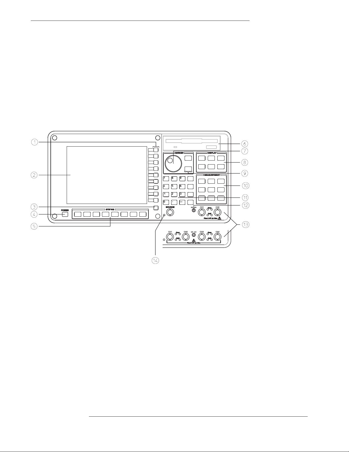
Agilent 35670A Front Panel
1-Use the softkeys to select items from the current menu. A softkey’s function is indicated by a video label on the analyzer’s screen.
Throughout this book, softkeys are printed like this: [
Hardkeys are front-panel buttons whose functions are always the same. They have a label printed directly on the key itself.
Throughout this book, hardkeys are printed like this: [
FFT ANALYSIS
Inst Mode
].
].
2-The analyzer’s screen is divided into the menu area and the display area. The menu area displays video labels for the softkeys. The
data area displays measurement data and information about the parameter settings.
3-The [
] key returns the menu to the previous level.
Rtn
4-The POWER switch turns on the analyzer.
5-Use the SYSTEM keys to control various system-level functions. These functions include saving files, plotting measurement data,
and accessing online help.
6-Use the disk drive to save your work on 3.5 inch flexible disks.
7-The knob moves the markers and the cursor. It also steps through numeric values and scrolls through online help.
8-Use the DISPLAY keys to control what appears on the analyzer’s traces. They only affect how data is displayed; DISPLAY keys
do not change measurement parameters.
You can press keys in the DISPLAY menus without losing measurement parameters.
9-Use the MARKER keys to select a variety of marker features.
10-Use the MEASUREMENT keys to control the analyzer’s source and inputs. They also control measurement parameters. You
must make a new measurement if you change a MEASUREMENT parameter.
11-Use the numeric-entry keys to enter a numeric value.
12-The microphone power connector provides power (8 Vdc) for the Microphone Adapter Kit (Option UK4).
13-The connector area of the front panel has two different configurations. The standard analyzer has a source output connector and
two input connectors. The 4-channel analyzer (Option AY6) has four input connectors.
Range indicators are located next to each input connector. The upper LED is the over-range indicator (the signal level exceeds the
current range setting). The lower LED is the half range indicator (the signal level exceeds half the current range setting).
14-A source on/off indicator is located at the left edge of the connector area.
The standard Agilent 35670A (2-channel) has a source connector on the front panel.
Page 4
The Agilent 35670A at a Glance (Rear Panel)
Page 5

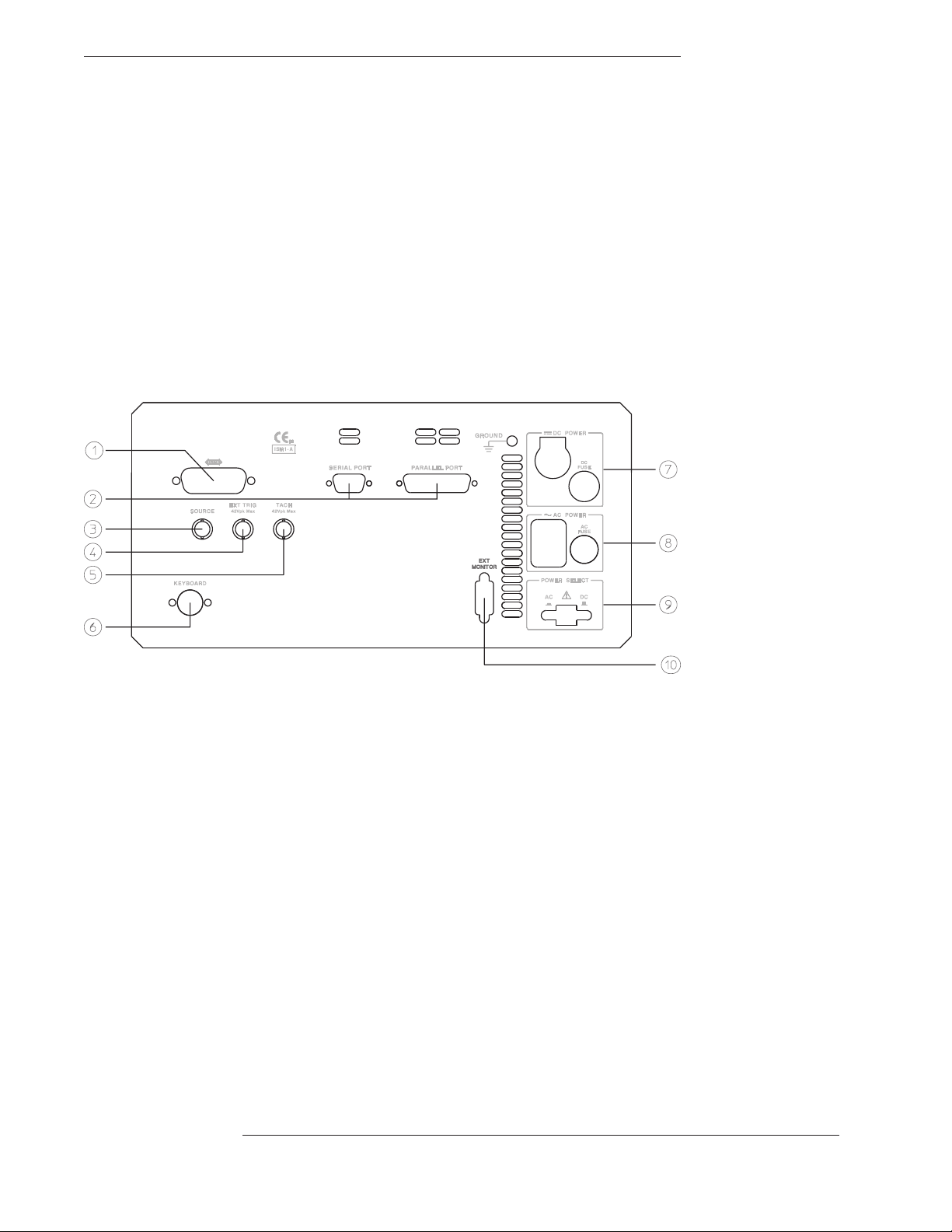
Agilent 35670A Rear Panel
1-The GPIB connector links the Agilent 35670A to other GPIB devices. GPIB parameters are set in the [
[
Plot/Print
] menus.
Local/GPIB
] and
2-The SERIAL PORT and the PARALLEL PORT link the analyzer to plotters and printers. These parameters are set in the
[
Plot/Print
] menu.
3-The SOURCE connector outputs the analyzer’s source signal. An LED on the front panel indicates if the source is on or off. The
source parameters are set in the [
The standard Agilent 35670A (2-channel) also has a source connector on the front panel.
4-The EXT TRIG connector links the analyzer to an external trigger signal. The external trigger parameters are set in the [
menu.
5-The TACH connector links the analyzer to a tachometer. The tachometer parameters are set in the [
Source
] menu.
Input
Trigger
] menu.
6-The KEYBOARD connector attaches an optional keyboard to the analyzer.
7-The DC POWER connector accepts DC power levels from 12 - 28 Vdc (nominal).
8-The AC POWER connector accept a wide range of ac voltage levels.
9-The POWER SELECT switch determines whether the analyzer is powered via the AC POWER connector or the DC POWER
connector.
10-The EXT MONITOR port links the analyzer to multi-sync monitors.
]
Page 6

Saftey Summary
The following general safety precautions must be observed during all phases of
operation of this instrument. Failure to comply with these precautions or with
specific warnings elsewhere in this manual violates safety standards of design,
manufacture, and intended use of the instrument. Agilent Technologies, Inc.
assumes no liability for the customer’s failure to comply with these
requirements.
GENERAL
This product is a Safety Class 1 instrument (provided with a protective earth
terminal). The protective features of this product may be impaired if it is used in
a manner not specified in the operation instructions.
All Light Emitting Diodes (LEDs) used in this product are Class 1 LEDs as per
IEC 60825-1.
ENVIRONMENTAL CONDITIONS
This instrument is intended for indoor use in an installation category II, pollution
degree 2 environment. It is designed to operate at a maximum relative humidity
of 95% and at altitudes of up to 2000 meters. Refer to the specifications tables
for the ac mains voltage requirements and ambient operating temperature range.
BEFORE APPLYING POWER
Verify that the product is set to match the available line voltage, the correct fuse
is installed, and all safety precautions are taken. Note the instrument’s external
markings described under Safety Symbols.
GROUND THE INSTRUMENT
To minimize shock hazard, the instrument chassis and cover must be connected
to an electrical protective earth ground. The instrument must be connected to
the ac power mains through a grounded power cable, with the ground wire
firmly connected to an electrical ground (safety ground) at the power outlet.
Any interruption of the protective (grounding) conductor or disconnection of
the protective earth terminal will cause a potential shock hazard that could
result in personal injury.
Page 7

FUSES
Only fuses with the required rated current, voltage, and specified type (normal
blow, time delay, etc.) should be used. Do not use repaired fuses or
short-circuited fuse holders. To do so could cause a shock or fire hazard.
DO NOT OPERATE IN AN EXPLOSIVE ATMOSPHERE
Do not operate the instrument in the presence of flammable gases or fumes.
DO NOT REMOVE THE INSTRUMENT COVER
Operating personnel must not remove instrument covers. Component
replacement and internal adjustments must be made only by qualified service
personnel.
Instruments that appear damaged or defective should be made inoperative and
secured against unintended operation until they can be repaired by qualified
service personnel.
WARNING The WARNING sign denotes a hazard. It calls attention to a procedure,
practice, or the like, which, if not correctly performed or adhered to,
could result in personal injury. Do not proceed beyond a WARNING
sign until the indicated conditions are fully understood and met.
Caution The CAUTION sign denotes a hazard. It calls attention to an operating
procedure, or the like, which, if not correctly performed or adhered to, could
result in damage to or destruction of part or all of the product. Do not proceed
beyond a CAUTION sign until the indicated conditions are fully understood and
met.
Page 8
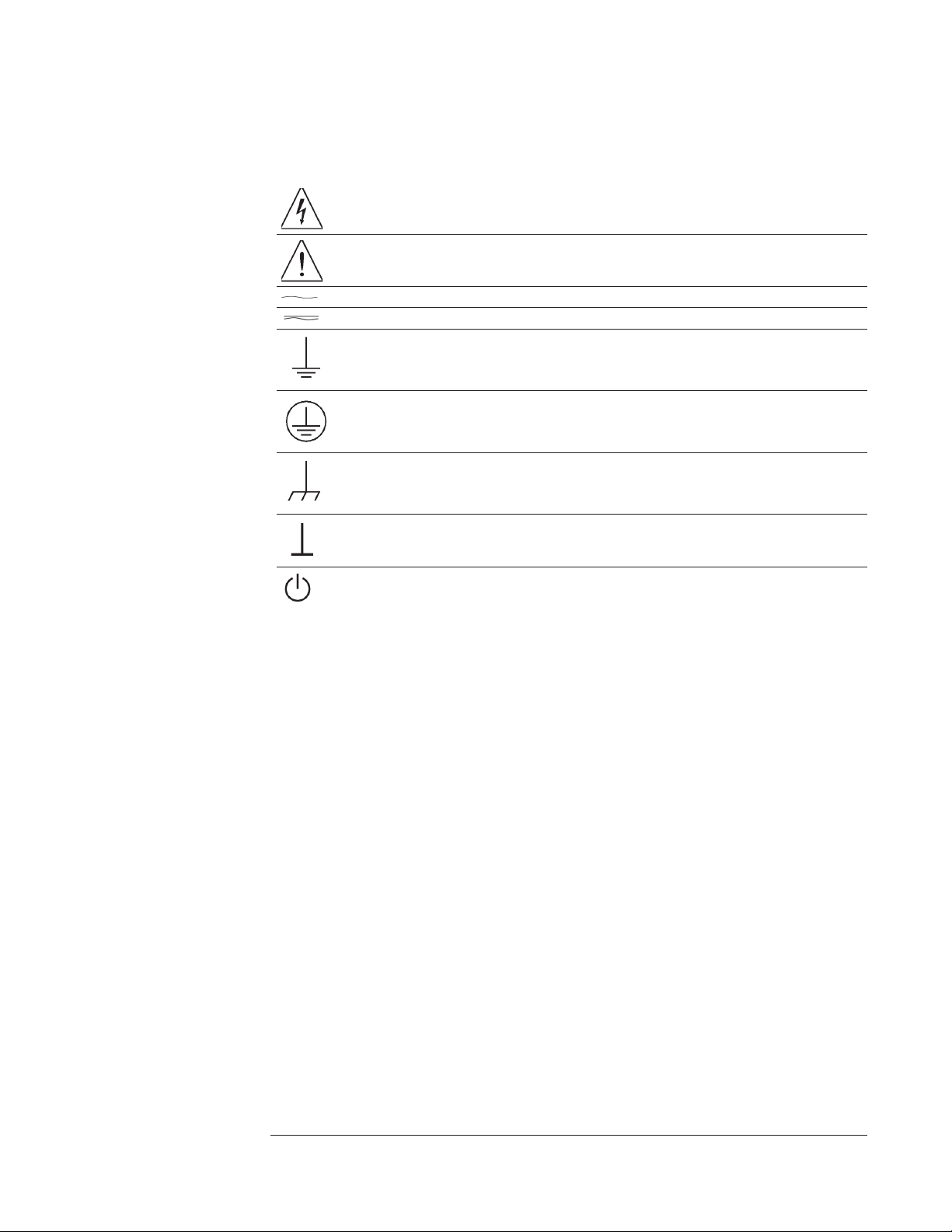
Safety Symbols
Warning, risk of electric shock
Caution, refer to accompanying documents
Alternating current
Both direct and alternating current
Earth (ground) terminal
Protective earth (ground) terminal
Frame or chassis terminal
Terminal is at earth potential.
Standby (supply). Units with this symbol are not completely disconnected from ac mains when
this switch is off
Page 9

Accessories
The accessories listed in the following table are supplied with the
Agilent 35670A.
Supplied Accessories Part Number
Line Power Cable See page 2-4
Standard Data Format Utilities HP 5061-8042
Agilent 35670A Operator’s Guide Agilent 35670-90053
Agilent 35670A Quick Start Agilent 35670-90056
Agilent 35670A Installation and Verification Guide Agilent 35670-90054
Agilent 35670A GPIB Command Reference Agilent 35670-90057
GPIB Programmer’s Guide Agilent 5960-5708
Agilent 35670A GPIB Commands: Quick Reference Agilent 35670-90048
The accessories listed in the following table are available for the
Agilent 35670A.
Available Accessories Part Number
DC Power Cable, 3 meter HP 35250A
DC Power Cable with Cigarette Lighter Adapter HP 35251A
Box of ten 3.5-inch double-sided, double-density disks HP 92192A
Using Instrument BASIC with the Agilent 35670A Agilent 35670-90049
Instrument BASIC User’s Handbook HP E2083-90000
HP Thinkjet Printer HP 2225A
HP Quietjet Printer HP 2227A
HP Jet Paper, 2500 sheets HP 92261N
GPIB Cable, 1 meter HP 10833A
GPIB Cable, 2 meter HP 10833B
GPIB Cable, 4 meter HP 10833C
GPIB Cable, 0.5 meter HP 10833D
Page 10

In This Book
This guide provides instructions for installing, verifying performance, and repairing
the Agilent 35670A Dynamic Signal Analyzer.
Chapter 1, ‘’Specifications,’’ lists the specifications for the Agilent 35670A and the
specifications for the required test equipment.
Chapter 2, ‘’Preparing the Analyzer for Use,’’ provides step-by-step instructions for
getting the analyzer ready to use and instructions on cleaning the screen, storing, and
transporting.
Chapter 3, ‘’Verifying Specifications,’’ provides step-by-step instructions for
installing and running the semiautomated performance test software. This chapter also
provides illustrations that show the equipment set up for each test and a copy of the
test records.
Chapter 4, ‘’Troubleshooting the Analyzer,’’ provides step-by-step instructions for
isolating most failures to the faulty assembly.
Chapter 5, ‘’Adjusting the Analyzer,’’ provides step-by-step instructions for adjusting
the analyzer.
Chapter 6, ‘’Replacing Assemblies,’’ provides step-by-step instructions to follow
before and after replacing an assembly. This chapter also provides step-by-step
instructions for disassembling the analyzer.
Chapter 7, ‘’Replaceable Parts,’’ provides ordering information and lists the
replaceable parts.
Chapter 8, ‘’Circuit Descriptions,’’ provides the overall instrument description and
individual assembly descriptions.
Chapter 9, ‘’Voltages and Signals,’’ shows where the signals and voltages are used in
the analyzer and describes each signal.
Chapter 10, ‘’Internal Test Descriptions,’’ describes the power-on test, calibration
routine, fault log messages, and self tests.
Chapter 11, ‘’Backdating,’’ provides information necessary to modify this manual for
instruments that differ from those currently being produced.
Chapter 12, ‘’Quick Reference,’’ shows assembly locations, cable connections, and all
the block diagrams.
Page 11

Table of Contents
1 Specifications
Frequency 1-3
Single Channel Amplitude 1-4
FFT Dynamic Range 1-5
Input Noise 1-6
Window Parameters 1-6
Single Channel Phase 1-6
Cross Channel Amplitude 1-7
Cross Channel Phase 1-7
Input 1-8
Time Domain 1-9
Trigger 1-9
Tachometer 1-10
Source Output 1-11
Digital Interfaces 1-12
General Specifications 1-13
Order Tracking — Option 1D0 1-14
Swept Sine Measurements —Option 1D2 1-15
Arbitrary Waveform Source—Option 1D4 1-15
Real Time Octave Analysis — Option 1D1 1-16
Recommended Test Equipment 1-17
Page 12

2 Preparing the Analyzer for Use
To do the incoming inspection 2-5
To install the analyzer 2-7
To connect the analyzer to a dc power source 2-8
To change the fuses 2-10
To connect the analyzer to a serial device 2-11
To connect the analyzer to a parallel device 2-11
To connect the analyzer to an GPIB device 2-12
To connect the analyzer to an external monitor 2-13
To connect the optional keyboard 2-14
To connect the microphone adapter 2-16
To clean the screen 2-17
To store the analyzer 2-17
To transport the analyzer 2-18
If the analyzer will not power up 2-19
If the analyzer operates intermittently on dc power 2-20
3 Verifying Specifications
To load the program 3-7
To run the program in semiautomated mode 3-8
To run the program without a printer 3-10
To run the program in manual mode 3-12
To set up the self test 3-13
To set up the dc offset test 3-14
To set up the noise test 3-15
To set up the spurious signals test 3-16
To set up the amplitude accuracy test 3-17
To set up the flatness test 3-18
To set up the amplitude linearity test 3-19
To set up the A-weight filter test 3-20
To set up the channel match test 3-21
To set up the frequency accuracy test 3-22
Page 13

To set up the anti-alias filter test 3-23
To set up the input coupling test 3-24
To set up the harmonic distortion test 3-25
To set up the intermodulation distortion test 3-28
To set up the cross talk test 3-30
To set up the single channel phase accuracy test 3-34
To set up the external trigger test 3-35
To set up the tach function test 3-37
To set up the input resistance test 3-39
To set up the ICP supply test 3-41
To set up the source amplitude accuracy test 3-45
To set up the source output resistance test 3-46
To set up the source dc offset test 3-48
To set up the source flatness test 3-49
To set up the source distortion test 3-50
Measurement Uncertainty 3-56
Performance Test Record - Two Channel 1 of 14
Performance Test Record - Four Channel 1 of 20
Operation Verification Test Record - Two Channel 1 of 10
Operation Verification Test Record - Four Channel 1 of 15
Page 14

4 Troubleshooting the Analyzer
How to troubleshoot the analyzer 4-4
To perform initial verification 4-5
To troubleshoot the power supply 4-11
To troubleshoot power-up failures 4-15
To troubleshoot CPU, memory, and buses failures 4-18
To troubleshoot display failures 4-22
To troubleshoot IIC bus failures 4-25
To troubleshoot fast bus failures 4-29
To perform self tests 4-31
To troubleshoot self-test lockup failures 4-37
To troubleshoot intermittent failures 4-40
To troubleshoot performance test failures 4-42
To troubleshoot source and calibrator failures 4-45
To troubleshoot input and ADC failures 4-51
To troubleshoot input failures on four channel analyzers 4-54
To troubleshoot distortion failures 4-56
To troubleshoot disk drive failures 4-57
To troubleshoot auto-range failures 4-59
To troubleshoot DIN connector failures 4-61
To troubleshoot trigger failures 4-62
To troubleshoot memory battery failures 4-67
To troubleshoot microphone power and adapter failures 4-69
To troubleshoot tachometer failures 4-70
Page 15

5 Adjusting the Analyzer
To adjust the frequency reference 5-5
To adjust the source 5-6
To adjust the ADC gain, offset and reference 5-7
To adjust the input dc offset 5-10
To adjust common mode rejection 5-13
To adjust filter flatness 5-17
To adjust the display voltage 5-21
6 Replacing Assemblies
What to do before replacing the CPU assembly 6-3
What to do after replacing an assembly 6-4
To remove cover 6-6
To remove rear panel 6-7
To remove front panel 6-8
To remove disk drive 6-10
To remove CPU 6-11
To remove NVRAM 6-12
To remove memory 6-13
To remove power supply 6-14
To remove motherboard 6-16
To remove dc-dc converter 6-18
Page 16

7 Replaceable Parts
Ordering Information 7-2
Assemblies 7-4
Cables 7-6
Instrument Covers and Handles 7-7
Assembly Covers and Brackets 7-8
Front Panel Parts 7-9
Rear Panel Parts 7-10
Chassis Parts 7-11
Screws, Washers, and Nuts 7-12
Miscellaneous Parts 7-12
Option UK4 Parts 7-13
Page 17

8 Circuit Descriptions
Overall Instrument Description 8-2
A1 Input 8-6
A2 Input 8-12
A5 Analog 8-18
A6 Digital 8-22
A7 CPU 8-25
A8 Memory 8-30
A9 NVRAM 8-32
A10 Rear Panel 8-33
A11 Keyboard Controller 8-35
A12 BNC 8-36
A13 Primary Keypad 8-37
A14 Secondary Keypad 8-37
A15 Primary Keypad 8-37
A22 BNC 8-37
A90 Fan 8-38
A98 Power Supply 8-38
A99 Motherboard 8-39
A100 Disk Drive 8-39
A101 Display 8-39
A102 DC-DC Converter 8-39
Option UK4 Microphone Adapter and Power Supply 8-40
Page 18

9 Voltages and Signals
Assembly Locations and Connections 9-3
Power Supply Voltage Distribution 9-6
A1 Input 9-7
A2 Input 9-7
A8 Memory 9-8
A9 NVRAM 9-12
A10 Rear Panel 9-14
A11 Keyboard Controller 9-18
A12 BNC 9-20
A13 Primary Keypad 9-21
A14 Secondary Keypad 9-23
A22 BNC 9-24
A99 Motherboard 9-25
A100 Disk Drive 9-34
A101 Display 9-36
A102 DC-DC Converter 9-37
10 Internal Test Descriptions
Power-on Test Description 10-2
Calibration Routine Description 10-5
Fault Log Messages 10-9
Self-Test Descriptions 10-10
11 Backdating
12 Quick Reference
Index
Guide to Agilent 35670A Documentation
Need Assistance?
Page 19

1
Specifications
1-1
Page 20

Specifications
This chapter contains the specifications for the Agilent 35670A Dynamic
Signal Analyzer and the critical specifications for the equipment required to
test the Agilent 35670A.
Instrument specifications apply after 15 minutes warm-up and within 2 hours of
the last self-calibration. When the internal cooling fan has been turned OFF,
specifications apply within 5 minutes of the last self-calibration. All
specifications are with 400 line frequency resolution unless stated otherwise.
Four channel instruments are unspecified in the one channel mode where alias
protection filters are not connected.
Abbreviations
dBVrms = dB relative to 1 Volt rms.
dBfs = dB relative to full scale amplitude range. Full scale is approximately 2 dB below ADC
overload.
FS or fs Full scale; synonymous with input range.
Real Time or Online = Refer to the collecting and displaying of information with no dropouts
or missing information.
Rload = Load resistance connected to the analyzer’s source.
Typical = Typical, non-warranted, performance specification included to provide general
product information.
Vpk = Peak of the ac voltage.
1-2
Page 21

Agilent 35670A Specifications
Frequency
Frequency
Maximum range
1 channel mode
2 channel mode
4 channel mode (option AY6 only)
Spans
1 channel mode
2 channel mode
4 channel mode (option AY6 only)
Minimum resolution
1 channel mode
2 channel mode
4 channel mode (option AY6 only)
Maximum real-time bandwidth (FFT span for continuous data acquistion) (preset, fast averaging)
1 channel mode
2 channel mode
4 channel mode (option AY6 only)
Measurement rate (typical) (preset, fast averaging)
1 channel mode
2 channel mode
4 channel mode (option AY6 only)
Display update rate (typical)
(preset, fast average off)
102.4 kHz, 51.2 kHz (option AY6†)
51.2 kHz
25.6 kHz
195.3 mHz to 102.4 kHz
97.7 mHz to 51.2 kHz
48.8 mHz to 25.6 kHz
122 mHz (1600 line display)
61 mHz (1600 line display)
61 mHz (800 line display)
25.6 kHz
12.8 kHz
6.4 kHz
≥70 averages/second (≥170 with 100 line display)
≥33 averages/second
≥15 averages/second
5 updates/second
9 updates/second (single channel, single display,
undisplayed traces set with static data: e.g., data
register)
Accuracy
† Option AY6 single channel maximum range extends to 102.4 kHz without anti-alias filter protection.
±30 ppm (±0.003%)
1-3
Page 22

Specifications Agilent 35670A
Single Channel Amplitude
Single Channel Amplitude
Absolute amplitude accuracy (FFT)
(A combination of full scale accuracy, full
scale flatness, and amplitude linearity.)
FFT full scale accuracy at 1 kHz (0 dBfs)
FFT full scale flatness (0 dBfs) relative to 1
kHz
FFT amplitude linearity at 1 kHz
Measured on +27 dBVrms range with time
average, 0 to −80 dBfs.
Amplitude resolution (16 bits less 2 dB over-range)
with averaging
Residual dc response
FFT mode frequency display
(excludes A-weight filter)
±2.92% (0.25 dB) of reading
±0.025% of full scale
±0.15 dB (1.74%)
±0.2 dB (2.33%)
±0.58% (0.05 dB) of reading
±0.025% of full scale
0.0019% of full scale (typical)
<−30 dBfs or -66dBVdc (0.5 mVdc) (whichever is
greater)
1-4
Page 23
Agilent 35670A Specifications
FFT Dynamic Range
FFT Dynamic Range
Spurious free dynamic range
(Includes spurs, harmonic distortion,
intermodulation distortion, alias products)
Excludes alias responses at extremes of span.
Source impedance = 50 Ω
FFT noise floor (typical)
Flat top window, 64 RMS averages
<−80 dBfs (90 dB typical)
Harmonic distortion
Single tone (in band), ≤0 dBfs
Post-filter harmonic distortion (alias
responses) of a single tone ≤102.4 kHz, ≤0
dBfs
Intermodulation distortion
Two tones (in-band), each ≤−6.02 dBfs
Spurious and residual responses
Source impedance = 50 Ω
Frequency alias responses
Single tone (out of displayed range),
≤0 dBfs, ≤1 MHz (≤200 kHz with ICP on)
2.5% to 97.5% of the frequency span
Lower and upper 2.5% of frequency span
<−80 dBfs
<−80 dBfs
<−80 dBfs
<−80 dBfs
<−80 dBfs
<−65 dBfs
1-5
Page 24

Specifications Agilent 35670A
Input Noise
Input Noise
Input noise level
Flat top window, −51 dBVrms range, source impedance = 50 Ω, 32 rms averages
Above 1280 Hz
160 Hz to 1.28 kHz (6.4 kHz span)
Note: To calculate noise as dB below full scale:
Noise [dBfs] = Noise [dBVrms/
See ‘’Window Parameters,’’ below, for noise equivalent bandwidths (NEBW).
] + 10LOG(NEBW) – Range [dBVrms].
Hz
<–140 dBVrms/√—Hz
<–130 dBVrms/√—Hz<%0 >
Window Parameters
Uniform Hann Flat Top
−3 dB bandwidth †
Noise equivalent bandwidth †
Attenuation at ± 1/2 bin
Shape factor (−60 dB BW/−3dBBW)
† For 800 line displays. With 400, 200, or 100 line displays, multiply bandwidths by 2, 4, and 8,
respectively. With 1600 line displays (only available in 1 or 2 channel mode), divide bandwidths by 2.
0.125% of span
0.125% of span
4.0 dB
716
0.185% of span
0.1875% of span
1.5 dB
9.1
0.450% of span
0.4775% of span
0.01 dB
2.6
Single Channel Phase
Phase accuracy relative to external trigger
16 RMS averages, center of bin, dc coupled,
0 dBfs to −50 dBfs, 0 Hz < freq ≤ 10.24 kHz only
For Hann and flat top windows, phase is referenced to a cosine wave at the center of the time
record. For the uniform, force, and exponential windows, phase is referenced to a cosine wave
at the beginning of the time record.
1-6
±4.0 degree
Page 25

Agilent 35670A Specifications
Cross Channel Amplitude
Cross Channel Amplitude
FFT cross channel gain accuracy
Frequency response mode, same amplitude range
(AC coupled, Peroidic Chirp, Uniform Window, > =4Hz)
At full scale: Tested with 10 rms averages
on the −11 to +27 dBvrms ranges, and 100 rms
averages on the −51 dBVrms range
At −20 dBfs: Tested with 200 rms averages on
the −11 to +27 dBVrms ranges, and 2000 rms
averages on the −51 dBVrms range
Cross Channel Phase
Cross channel phase accuracy
(same conditions as cross-channel amplitude
>=12Hz)
±0.04 dB (0.46%)
±0.08 dB (0.92%)
±0.5 degree
1-7
Page 26

Specifications Agilent 35670A
Input
Input
Input ranges
(full scale) (auto-range capability)
Maximum input levels 42 Vpk
Input impedance
Low side to chassis impedance
Floating mode
Grounded mode
AC coupling rolloff <3 dB rolloff at 1 Hz
Common mode rejection ratio
Single tone at or below 1 kHz
–51 dBVrms to –11 dBVrms ranges
–9 dBVrms to +9 dBVrms ranges
+11 dBVrms to +27 dBVrms ranges
Note: CM dBfs = CM signal input [dBVrms] − CMRR [dB] − range [dBVrms]
Common mode range (floating mode)
Amplitude over-range detection +3 dB typical
ICP signal conditioning
+27 dBVrms (31.7 Vpk) to −51 dBVrms
(3.99 mVpk) in 2 dB steps
1MΩ ±10%, 90 pF nominal
1MΩ ±30%, <0.010 µF (typical)
≤100 Ω
>75 dB typical
>60 dB typical
>40 dB typical
±4 Vpk
Current source
Open circuit voltage
A-weight filter
Conforms to ANSI Standard S1.4-1983; and
to IEC 651-1979; 10 Hz to 25.6 kHz
Crosstalk
Between input channels, and source-to-input
(receiving channel source impedance = 50 Ω)
4.25 ±1.5 mA
+26 to +32 Vdc
Type 0 Tolerance
<–135 dB below signal or <–80 dBfs of
receiving channel, whichever response is
greater in amplitude
1-8
Page 27

Agilent 35670A Specifications
Time Domain
Time Domain
Specifications apply in histogram/time mode, unfiltered time display
DC amplitude accuracy
Rise time of −1 V to 0 V test pulse
Settling time of −1 V to 0 V test pulse
Pulse aberrations (peak overshoot)
of −1 V to 0 V test pulse
Peak aberration relative to the mode-to-mode
difference (most common values)
Sampling period
1 channel mode
2 channel mode
4 channel mode (option AY6 only)
±5.0%fs
<11.4 ms
<16 ms to 1%
<3 %
3.815 ms (1/262144 Hz) to2sin2× steps
7.629 ms (1/131072 Hz) to4sin2× steps
15.26 ms (1/65536 Hz) to8sin2× steps
Trigger
Trigger modes Internal trigger
External trigger
Source trigger
GPIB trigger
Maximum trigger delay
Post trigger
Pre trigger
No two channels can be further than ±7168 samples
from each other.
External trigger maximum input
External trigger range
Low range
High range
External trigger resolution
Low range
High range
8191 seconds
8191 sample periods
±42 Vpk
−2Vto+2V
−10 V to +10 V
15.7 mV
78 mV
1-9
Page 28

Specifications Agilent 35670A
Tachometer
Tachometer
Pulses per revolution 0.5 to 2048
RPM accuracy
Tachometer level range
Low range
High range
Tachometer level resolution
Low range
High range
Tachometer level accuracy (as a % of
tachometer range setting)
Maximum tachometer input level
Minimum tachometer pulse width 600 ns
Maximum tachometer pulse rate 400 kHz
±100 ppm (0.01%) (typical)
–4Vto+4V
–20 V to +20 V
100 mV
500 mV
±10% of range
±42 Vpk
1-10
Page 29

Agilent 35670A Specifications
Source Output
Source Output
Source types Sine, random noise, chirp, pink noise, burst
random, burst chirp
Amplitude range
AC amplitude resolution
Voltage ≥ 0.2 Vrms
Voltage < 0.2 Vrms
DC offset accuracy
Pink noise adder Add 600 mV typical when using pink noise
Output impedance
Maximum loading
Current
Capacitance
Sine amplitude accuracy at 1 kHz
Rload >250
0.1 Vpk to 5 Vpk
Sine flatness (relative to 1 kHz)
0.1 V to 5 V peak, 0 Hz to 102.4 kHz
Harmonic and sub-harmonic distortion and spurious signals (in band)
0.1 Vpk to 5 Vpk sine wave
Ω
ac:
±5 V peak †
±10V†
dc:
† Vac
2.5 mVpk
0.25 mVpk
+ |Vdc| ≤10 V
pk
±15 mV±3% of ( |Vdc| +Vac
Ω
<5
±20 mA peak
0.01 mF
±4% (0.34 dB) of setting
±1dB
) settings
pk
Fundamental <30 kHz
Fundamental ≥30 kHz
<−60 dBc
<−40 dBc
1-11
Page 30

Specifications Agilent 35670A
Digital Interfaces
Digital Interfaces
External keyboard Compatible with PC-style 101-key keyboard
model number HP C1405A (#ABA) (DIN
connector) and HP keyboard cable part
number 5081-2249.
GPIB Conforms to the following standards: IEEE
488.1 (SH1, AH1, T6, TEO, L4, LE0, RS1,
RL1, PP0, DC1, DT1, C1, C2, C3, C12, E2)
IEEE 488.2-1987
Complies with SCPI 1992
Factory set address: 11
Data transfer rate
(REAL 64 Format)
Serial port (printing, plotting) 300 baud to 9600 baud
Parallel port (printing, plotting)
<45 ms for a 401 point trace
1-12
Page 31

Agilent 35670A Specifications
General Specifications
General Specifications
Safety Standards CSA Certified for Electronic Test and
Measurement Equipment per CSA C22.2, No.
231
This product is designed for compliance to:
UL1244, Fourth Edition
IEC 348, Second Edition, 1978
EMI/RFI Standards CISPR 11
Acoustics LpA <55 dB (cooling fan at high speed
setting)
<45 dB (auto speed setting at 25° C)
Fan speed setting of high, automatic, and off are available. The fan off setting can be enabled
for a short period of time, except at higher ambient temperatures where the fan will stay on.
Environmental operating restrictions Operating:
disk in drive
Ambient temperature 4° to 45° C 0° to 55° C –40° to 70° C
Relative humidity (non-condensing)
minimum
maximum
Vibration (5 - 500 Hz) 0.6 Grms 2.1 Grms 3.41 Grms
Shock 5 G
Maximum altitude 4600 meters (15,000 feet)
AC power 90 Vrms to 264 Vrms (47 to 440 Hz)
DC power 12 Vdc to 28 Vdc nominal
DC current at 12 V (typical) 10 A (standard)
Warm-up time 15 minutes
Weight 15 kg (33 lb) net
20%
80% at 32° C
(10 ms 1/2 sine)5G(10 ms 1/2 sine)
350 VA maximum
200 VA maximum
12 A (4 channel, option AY6)
29 kg (64 lb) shipping
Operating:
no disk in drive
15%
95% at 40° C
Storage and
transport
5%
95% at 50° C
40 G
(3 ms 1/2 sine)
Dimensions
(Excluding bail handle and impact cover)
IEC 801-3 (Radiated Immunity) Performance degradation may occur at Severity Level 2.
Height: 190 mm (7.5 in)
Width: 340 mm (13.4 in)
Depth: 465 mm (18.3 in)
1-13
Page 32

Specifications Agilent 35670A
Order Tracking — Option 1D0
Order Tracking — Option 1D0
Max Order Max RPM
Real time (online)
1 channel mode
2 channel mode
4 channel mode
Capture playback †
1 channel mode
2 channel mode
4 channel mode
Specified for
5 ≤ RPM ≤ 60,000 (online), 5 ≤ RPM ≤ 491,519 (capture playback); and
number of orders ≤ 200
† Signals are captured online and then postprocessed in capture playback mode.
Delta order 1/128 to 1/1
Resolution
(maximum order)/(delta order)
Maximum RPM ramp rate
1000 to 10,000 RPM run up
maximum order = 10
delta order = 0.1
RPM step = 30 (1 channel)
= 60 (2 channel)
= 120 (4 channel)
60
×
≤
25,600 Hz
12,800 Hz
6,400 Hz
102,400 Hz
51,200 Hz
25,600 Hz
≤200
750 RPM/second (typical for real time)
Order track amplitude accuracy
1-14
±1 dB (typical)
Page 33

Agilent 35670A Specifications
Swept Sine Measurements —Option 1D2
Swept Sine Measurements —Option 1D2
Dynamic range
Default span: 51.2 Hz to 51.2 kHz
Fast average ON, 101 point log sweep
Tested with 11 dBVrms source level at 100 ms
integration (approximately 60 second sweep)
130 dB typical
Arbitrary Waveform Source—Option 1D4
Amplitude Range Arb: ±5 Vpk †
dc: ±10 V †
†V
+|Vdc| ≤10 V
pk
Record Length
Depends on measurement resolution (100,
200, 400, 800, and 1600 lines)
Point spacing Matches the measurement sample rate.
DAC Resolution
0.2828 Vpk to 5 Vpk
<0.2828 Vpk
# of points = 2.56 x lines of resolution, or # of
complex points = 1.28 x lines of resolution
2.5 mV
0.25 mV
1-15
Page 34

Specifications Agilent 35670A
Real Time Octave Analysis — Option 1D1
Real Time Octave Analysis — Option 1D1
Standards Conforms to ANSI Standard S1.11 - 1986,
Order 3, Type 1-D, Extended and Optional
Frequency Ranges
Conforms to IEC 651-1979 Type 0 Impulse,
and ANSI S1.4
Frequency ranges (at centers)
Online (real time)
1/1 octave
1/3 octave
1/12 octave
1 channel
0.063 Hz to 16 kHz
0.08 Hz to 40 kHz
0.0997 Hz to 12.338 kHz
2 channel
0.063 Hz to 8 kHz
0.08 Hz to 20 kHz
0.0997 Hz to 6.169 kHz
4 channel
0.063 Hz to 4 kHz
0.08 Hz to 10 kHz
0.0997 Hz to 3.084 kHz
Capture playback
1/1 octave
1/3 octave
1/12 octave
1 channel
0.063 Hz to 16 kHz
0.08 Hz to 31.5 kHz
0.0997 Hz to 49.35 kHz
2 channel
0.063 Hz to 16 kHz
0.08 Hz to 31.5 kHz
0.0997 Hz to 49.35 kHz
4 channel
0.063 Hz to 16 kHz
0.08 Hz to 31.5 kHz
0.0997 Hz to 49.35 kHz
1 to 12 octaves can be measured and
displayed.
1/1, 1/3, and 1/12 octave true center frequencies related by the formula:
()
fi
+
1
n
1
==
2
()
fi
Where 1000 Hz is the reference for 1/1, 1/3 octave, and 1000 x2
; n 1, 3 or 12;
(1/24)
Hz is the reference for
1/12 octave. The marker returns the ANSI standard preferred frequencies.
Accuracy
±0.2 dB
1 second stable average
single tone at band center
Readings are taken from the linear total power spectrum bin. It is derived from sum of each
filter.
1/3 octave dynamic range
2 second stable average, limited by input noise
level
1-16
>80 dB (typical) per ANSI S1.11 - 1986
Page 35

Agilent 35670A Specifications
Recommended Test Equipment
Recommended Test Equipment
The following table lists the recommended equipment needed to test the performance
of the Agilent 35670A Dynamic Signal Analyzer. The table on page 1-20 lists
additional equipment needed to adjust and troubleshoot the analyzer. Other equipment
may be substituted for the recommended model if it meets or exceeds the listed critical
specifications. When substitutions are made, you may have to modify the procedures
to accommodate the different operating characteristics.
Recommended Test Equipment
Instrument Critical Specifications Recommended Model
AC Calibrator 10 Hz to 102.4 kHz; 1 mV to 10 V
Amplitude
Amplitude Accuracy: ±0.1% phase locking
capability
Frequency
Synthesizer
Low Distortion
Oscillator
Digital
Multimeter
Frequency Range: 10 Hz to 1 MHz
Frequency Accuracy: ≤5 ppm
Amplitude Accuracy:
0.2 dB from 1 Hz to 100 kHz
1 dB from 100 kHz to 1 MHz
Harmonic Distortion: ≤–70 dBc
Spurious: ≤–70 dBc
<±1 deg phase shift between output and
sync
Frequency Range: 10 Hz to 100 kHz
Harmonic Distortion: ≤–93 dB, 10 Hz to
20 kHz
5 1/2 digit True rms ac Voltage:
30 Hz to 100 kHz; 0.1 to 500 V; ±0.1%;
≥1MΩ input impedance dc Voltage:
1 V to 300 V; ±0.1%
Fluke 5700A †
Alternate
Fluke 5200A †
Datron 4200, 4700, or 4708 ‡
HP 745A
HP 3326A
Alternate
(2) HP 3325A/B Opt 001
HP 339A ††
Alternate
HP 3326A with notch filter ††
HP 3325A/B with notch
filter††
HP 3458A
Alternate
HP 3456A , HP 3455A
HP 3478A
Feedthrough
Termination (2)
(4 for option
AY6)
† John Fluke Manufacturing Co., Inc., PO Box C9090, Everett, WA 98206 U.S.A. (206) 347-6100
‡ Wavetek, 5808 Churchman Bypass, Indianapolis, IN 46203 U.S.A.
†† This equipment is not required for Operation Verification. The parts and schematic for the notch
filter are shown on page 1-19.
‡‡ ITT Pomona Electronics, 1500 East Ninth Street, Pomona, CA 91769 U.S.A. (714) 469-2900
FAX (206) 629-3317
50 Ω: ±2% at dc
Pomona Elect Model 4119-50
‡‡
Alternate
HP 11048C, HP 10100C
1-17
Page 36

Specifications Agilent 35670A
Recommended Test Equipment
Recommended Test Equipment (continued)
Instrument Critical Specifications Recommended Model
Cables BNC-to-Dual Banana
(6) BNC-to-BNC 30 cm
BNC-to-BNC 122 cm
Adapters BNC(m)-to-Dual Banana Plug
BNC(f)-to-Dual Banana Plug
BNC(f)-to-BNC (f)
(4) BNC Tee (m)(f)(f)
Resistor (2)†
† See the following for suggested assembly.
Value: 1 kΩ
Accuracy: 1%
Power: 0.25W
HP 11001-60001
HP 8120-1838
HP 8120-1840
HP 10110B
HP 1251-2277
HP 1250-0080
HP 1250-0781
HP 0757-0280
Suggested Assembly for Series Resistor
The following is a suggested assembly for the 1 kΩ series resistor. Two 1 kΩ
series resistors are required for the Intermodulation Distortion performance
test.
• Cut resistor leads to 12 mm on each end.
• Solder one resistor lead to the center conductor of the BNC female connector.
•
Solder the conductor center pin to the other lead of the resistor.
•
Screw the sleeve and the BNC male connector into place. Tighten securely.
1-18
Page 37

Agilent 35670A Specifications
Recommended Test Equipment
Schematic and Parts List for Notch Filter
The Harmonic Distortion performance test requires either an HP 339A or an
HP 3326A or HP 3325A/B with notch filter. The following shows the schematic and
parts list for the notch filter.
Reference Description Agilent Part
Number
C1-C4
R1-R2
R3
R4-R6
0.025 µF ±2.5%, 100 V polypropelene-metalized
249 Ω±1% metal film, 0.125 W
118 Ω±1% metal film, 0.125 W
20 Ω trimmer, 1 turn
HP 0160-6809
HP 0698-4421
HP 0698-4407
HP 2100-3409
1-19
Page 38

Specifications Agilent 35670A
Recommended Test Equipment
Additional Recommended Test Equipment
Instrument Critical Specifications Recommended Model
Frequency Counter Frequency Range: 0 Hz to 100 MHz
Frequency Accuracy: 7.5 ppm or better
at 20 MHz
Oscilloscope Bandwidth: >50 MHz
Two Channel; External Trigger; 1 MΩ
Input
Oscilloscope Probe
Impedance: ≥1MΩ
HP 5350B
Alternate
HP 5351B, HP 5335A
HP 54111D
Alternate
HP 1980B, HP 1740
HP 10431A
Division Ratio: 10:1
Maximum Voltage: ≥20 Vdc
Oscilloscope Probe
Impedance: ≥ 1MΩ
HP 10438A
Division Ratio: 1:1
Spectrum Analyzer Frequency Range: 10 Hz to 100 kHz
Dynamic Range: ≥70 dB
HP 3562A
Alternate
HP 3561A, HP
3585A/B
Logic Probe TTL HP 545A
Alternate
HP 5006A,
HP5005A/B
Patch Cord Minigrabber test clips Pomona 3781-8-7
Cable BNC(m)-to-SMB(f) HP 03585-61616
Adapter SMB(m)-to-SMB(m) HP 1250-0669
1-20
Page 39

2
Preparing the Analyzer for
Use
2-1
Page 40

Preparing the Analyzer for Use
This chapter contains instructions for inspecting and installing the
Agilent 35670A Dynamic Signal Analyzer. This chapter also includes
instructions for cleaning the screen, transporting and storing the analyzer.
DC Power Requirements
The analyzer can operate from a dc power source supplying a true range of 10.8
to 30.8 Vdc. With all options installed, power consumption is less than
200 VA. The following table shows typical current requirements at different
operating voltages for the standard two-channel analyzer and for the optional
four-channel analyzer.
Operating Typical Current
Voltage Standard 2 channel
Agilent 35670A
12 Vdc 8.0 amps 11.0 amps
24 Vdc 4.0 amps 5.5 amps
Optional 4 channel Agilent 35670A
AC Power Requirements
The analyzer can operate from a 47 to 440 Hz, single-phase, ac power source
supplying 90 to 264 Vrms. With all options installed, power consumption is
less than 350 VA.
Warning Only a qualified service person, aware of the hazards involved, should measure
the line voltage.
2-2
Page 41

Agilent 35670A Preparing the Analyzer for Use
DC Power Cable and Grounding Requirements
The negative side of the dc input connector is not connected to chassis ground.
In dc mode operation, the chassis will float. The chassis ground lug on the rear
panel and the negative side of the dc input connector should both be connected
to a known reference potential.
Two dc power cables are available—the HP 35250A dc power cable and the
HP 35251A dc power cable with cigarette lighter adapter. Both cables contain
a 30 amp, 32 volt fuse (HP 2110-0920).
Warning The tip of the cigarette lighter adapter may get hot during use. After unpluging
the adapter, be careful of the heat from the adapter’s tip.
Caution Although shorter cables may reduce dc voltage loss, use the standard cables. The dc
inrush current may pit the connector contacts in shorter cables.
AC Power Cable and Grounding Requirements
On the GPIB connector, pin 12 and pins 18 through 24 are tied to chassis
ground and the GPIB cable shield. The instrument frame, chassis, and covers
are connected to chassis ground. The input BNCs are floating unless ground
mode is selected.
The analyzer is equipped with a three-conductor power cord that grounds the
analyzer when plugged into an appropriate receptacle. The type of power cable
plug shipped with each analyzer depends on the country of destination. The
following figure shows available power cables and plug configurations.
2-3
Page 42

Preparing the Analyzer for Use Agilent 35670A
*The number shown for the plug is the industry identifier for the plug only, the number shown for the
cable is an HP part number for a complete cable including the plug.
**UL listed for use in the United States of America.
Warning The power cable plug must be inserted into an outlet provided with a protective
earth terminal. Defeating the protection of the grounded analyzer cabinet can
subject the operator to lethal voltages.
2-4
Page 43

Agilent 35670A Preparing the Analyzer for Use
To do the incoming inspection
To do the incoming inspection
The Agilent 35670A Dynamic Signal Analyzer was carefully inspected both
mechanically and electrically before shipment. It should be free of marks or scratches,
and it should meet its published specifications upon receipt.
Inspect the analyzer for physical damage incurred in transit. If the analyzer
•
was damaged in transit, do the following:
Save all packing materials.
•
File a claim with the carrier.
•
Call your Agilent Technologies sales and service office.
•
Warning If the analyzer is mechanically damaged, the integrity of the protective earth
ground may be interrupted. Do not connect the analyzer to power if it is
damaged.
• Check that the POWER SELECT switch on the analyzer’s rear panel is set to
the AC position.
The switch is in the AC position when in the ‘’in’’ position.
2-5
Page 44

Preparing the Analyzer for Use Agilent 35670A
To do the incoming inspection
Check that the correct fuses are installed in the fuse holders.
•
An 8 amp, 250 volt, normal blow fuse is required for ac operation. A 30 amp, 32 volt,
normal blow fuse is required for dc operation. Both fuses are installed at the factory.
For instructions on removing the fuses or fuse part numbers, see ‘’To change the
fuses.’’
Using the supplied power cord, connect the analyzer to an appropriate
•
receptacle.
The analyzer is shipped with a three-conductor power cord that grounds the analyzer
when plugged into an appropriate receptacle. The type of power cable plug shipped
with each analyzer depends on the country of destination.
Set the analyzer’s power switch to on.
•
Press the switch located on the analyzer’s lower left-hand corner. The switch is in the
on ( l ) position when in the ‘’in’’ position. The analyzer requires about 20 seconds to
complete its power-on routine.
Test the electrical performance of the analyzer using the operation verification
•
or the performance tests in chapter 3, ‘’Verifying Specifications.’’
The operation verification tests verify the basic operating integrity of the analyzer;
these tests take about
The performance tests verify that the analyzer meets all the performance
specifications; these tests take about
1
hours to complete and are a subset of the performance tests.
1
2
1
hours to complete.
2
2
2-6
Page 45

Agilent 35670A Preparing the Analyzer for Use
To install the analyzer
To install the analyzer
The analyzer is shipped with rubber feet and bail handle in place, ready for use as a
portable or bench analyzer.
Install the analyzer to allow free circulation of cooling air.
•
Cooling air enters the analyzer through the right side and exhausts through the left side
and rear panel.
To install the analyzer in an equipment cabinet, follow the instructions shipped with
•
the rack mount kit.
Warning To prevent potential fire or shock hazard, do not expose the analyzer to rain or
other excessive moisture.
Protect the analyzer from moisture and temperatures or temperature changes that cause
•
condensation within the analyzer.
The operating environment specifications for the analyzer are listed in chapter 1,
‘’Specifications.’’
Protect the analyzer’s disk drive from dirt and dust.
•
Remove the screw to the right of the disk drive and use it to attach the supplied disk
drive cover. The disk drive cover is located inside the front-panel impact cover.
Caution Use of the equipment in an environment containing dirt, dust, or corrosive substances
will drastically reduce the life of the disk drive and the flexible disks. To minimize
damage, use the disk drive cover and store the flexible disks in a dry, static-free
environment.
2-7
Page 46

Preparing the Analyzer for Use Agilent 35670A
To connect the analyzer to a dc power source
To connect the analyzer to a dc power source
In applications requiring a portable dc power source, use a properly protected dc
power system. The dc system should contain a deep cycle battery rather than a
standard automobile battery. A standard automobile battery will fail prematurely if
repeatedly discharged. Also, select a battery that provides the best compromise
between operation time and portability.
Set the analyzer’s power switch to off (
•
Set the analyzer’s POWER SELECT switch to the DC position.
•
The switch is in the DC position when in the ‘’out’’ position.
Connect the dc power cable to the dc power source.
•
Using the dc power cable (HP 35250A), attach the black cable to the common terminal
and the red cable to the positive terminal of the dc power source. Using the dc power
cable with cigarette lighter adapter (HP 35251A), plug the cigarette lighter adapter into
an automotive cigarette lighter receptacle.
Connect the analyzer’s ground terminal to the same reference potential as the
•
common terminal of the dc power source.
Using a wire, connect the analyzer’s GROUND terminal to the common terminal of
the dc source. If you are using the dc power cable with cigarette lighter adapter,
connect the GROUND terminal to the automobile chassis.
• Plug the dc power cable into the analyzer’s DC POWER receptacle. Make sure
to align the red dot on the plug with the red dot on the receptacle.
O ).
2-8
Page 47

Agilent 35670A Preparing the Analyzer for Use
To connect the analyzer to a dc power source
Turn on the dc power source.
•
If the dc power source is supplied by an automobile, start the automobile. The
automobile must be running to provide adequate dc power.
Warning The tip of the cigarette lighter adapter may get hot during use. After unpluging
the adapter, be careful of the heat from the adapter’s tip.
Set the analyzer’s power switch to on (
•
l ).
If the analyzer will not power up or operates intermittently on dc power, see ‘’If the
analyzer will not power up’’ or ‘’If the analyzer operates intermittently on dc power’’
at the end of this chapter.
2-9
Page 48

Preparing the Analyzer for Use Agilent 35670A
To change the fuses
To change the fuses
Both fuses are installed at the factory.
Unplug the power cord from the analyzer.
•
Press in and turn the appropriate fuse holder cap counter-clockwise (use a
•
small screw driver for the ac fuse). Remove when the fuse cap is free from the
housing.
Pull the fuse from the fuse holder cap.
•
To reinstall, select the proper fuse and place in the fuse holder cap.
•
DC Fuse AC Fuse
HP 2110-0920 30 A 32 V Normal Blow HP 2110-0342 8 A 250 V Normal Blow
Place the fuse holder cap in the housing. Press in and turn clockwise.
•
2-10
Page 49

Agilent 35670A Preparing the Analyzer for Use
To connect the analyzer to a serial device
To connect the analyzer to a serial device
The Serial Port is a 9-pin, EIA-574 port that is only available using option 1C2,
Instrument Basic. The total allowable transmission path length is 50 feet.
Connect the analyzer’s rear panel SERIAL PORT to a serial device using a 9-pin
•
female to 25-pin RS-232-C cable.
Part Number Cable Description
HP 24542G 9-pin female to 25-pin male RS-232
HP 24542H 9-pin female to 25-pin female RS-232
For additional information, see chapter 9 in the Agilent 35670A Service Guide.
To connect the analyzer to a parallel device
The Parallel Port is a 25-pin, Centronics port. The Parallel Port can interface with
PCL printers or HP-GL plotters.
• Connect the analyzer’s rear panel PARALLEL PORT connector to a plotter or printer
using a Centronics interface cable.
Part Number Cable Description
HP 92284A 25-pin male to 36-pin male 2-meter Centronics
HP C2912B 25-pin male to 36-pin male 3-meter Centronics
For additional information, see chapter 9 in the Agilent 35670A Service Guide.
2-11
Page 50

Preparing the Analyzer for Use Agilent 35670A
To connect the analyzer to an GPIB device
To connect the analyzer to an GPIB device
The analyzer is compatible with the Agilent Technologies Interface Bus (GPIB). The
GPIB is Agilent Technologies’s implementation of IEEE Standard 488.1. Total
allowable transmission path length is 2 meters times the number of devices or 20
meters, whichever is less. Operating distances can be extended using an GPIB
Extender.
GPIB peripherals include HP-GL plotters, PCL printers, and SS-80 external disks.
Connect the analyzer’s rear panel GPIB connector to an GPIB device using an
•
GPIB interface cable.
Caution The analyzer contains metric threaded GPIB cable mounting studs as opposed to
English threads. Use only metric threaded GPIB cable lockscrews to secure the cable
to the analyzer. Metric threaded fasteners are black, while English threaded fasteners
are silver.
For GPIB programming information, see the Agilent 35670A GPIB Programming
Reference.
2-12
Page 51

Agilent 35670A Preparing the Analyzer for Use
To connect the analyzer to an external monitor
To connect the analyzer to an external monitor
The External Monitor connector is a 9-pin D female miniature connector that can
interface with an external, multisync monitor. The monitor must be compatible with
the 24.8 kHz line rate, 55 Hz frame rate, and TTL signals provided by the
Agilent 35670A. A SONY CPD-1302 monitor and a NEC Multisync 3D monitor with
EZPIXpc† driver has been checked and found compatible with the Agilent 35670A
external monitor mode operation.
Set the analyzer’s power switch to on (
•
Set the monitor’s power switch to on and configure the input and timing mode
•
if necessary.
See the manual supplied with the monitor for information on configuring the monitor’s
input and timing mode.
Connect the external monitor’s input cable to the analyzer’s rear panel EXT
•
MONITOR connector.
A cable with a 9-pin connector option or an adapter to a 9-pin connector is required to
connect the monitor to the Agilent 35670A.
• Press the following keys to enable external mode:
[
Disp Format ]
[
MORE ]
[
MORE ]
[
EXT MON ON OFF ]
l ).
Pin Number Signal Name Pin Number Signal Name
3 R 8 HSYNC
4 G 9 VSYNC
5 B 1, 2, 6 GND
† The EZPIXpc driver converts TTL video signals into RGB analog signals, drives 75 ohm coax cable,
provides RGB composite sync or RGB sync on green, for monitors with RGB input capability. EZPIXpc,
Covid, Inc., 1725 West 17th St, Tempe, Arizona 85281, 800-638-6104
2-13
Page 52

Preparing the Analyzer for Use Agilent 35670A
To connect the optional keyboard
To connect the optional keyboard
The analyzer may be connected to an optional external keyboard. The keyboard
remains active even when the analyzer is not in alpha entry mode. This means that
you can operate the analyzer using the external keyboard rather than the front panel.
Pressing the appropriate keyboard key does the same thing as pressing a hardkey or a
softkey on the analyzer’s front panel.
Set the power switch to off (
•
Caution Do not connect or disconnect the keyboard cable with the line power turned on ( l ).
Connecting or disconnecting the keyboard while power is applied may damage the
keyboard or the analyzer.
Connect the round plug on the keyboard cable to the KEYBOARD connector
•
on the analyzer’s rear panel. Make sure to align the plug with the connector
pins.
O ).
2-14
Page 53

Agilent 35670A Preparing the Analyzer for Use
To connect the optional keyboard
Connect the other end of the keyboard cable to the keyboard.
•
Caution In addition to the U.S. English keyboard, the Agilent 35670A Dynamic Signal
Analyzer supports U.K. English, German, French, Italian, Spanish, and Swedish. Use
only the Agilent Technologies approved keyboard for this product. Agilent
Technologies does not warrant damage or performance loss caused by a non-approved
keyboard. See the beginning of this guide for part numbers of approved Agilent
Technologies keyboards.
To configure your analyzer for a keyboard other than U.S. English, press
•
[
System Utility][KEYBOARD SETUP
]. Then press the appropriate softkey to
select the language.
Configuring your analyzer to use a keyboard other than U.S. English only ensures that
the analyzer recognizes the proper keys for that particular keyboard. Configuring your
analyzer to use another keyboard does not localize the on-screen annotation or the
analyzer’s online HELP facility.
2-15
Page 54

Preparing the Analyzer for Use Agilent 35670A
To connect the microphone adapter
To connect the microphone adapter
The Microphone Adapter and Power Supply (option UK4) simplifies microphone
connections. The mic connector on the analyzer’s front panel provides 8 Vdc to power
the adapter. The adapter’s internal power supply uses a step-up converter to provide
28 V and 200 V on the seven-pin input connectors. The 28 V pins power the
microphone pre-amplifiers. The 200 V pins polarize the condenser microphone
cartridges.
Flip the bail handle down to support the front of the analyzer.
•
Insert the threaded ends of the adapter’s two knurled knobs into the standoffs
•
on the bottom of the analyzer’s case, then tighten the knobs with your fingers.
Attach the adapter’s mic cable to mic connector on the analyzer’s front panel.
•
Connect the adapter’s BNCs to the corresponding BNCs on the analyzer’s
•
front panel.
Standard 2 channel Agilent 35670A Optional 4 channel
Agilent 35670A
2-16
Page 55

Agilent 35670A Preparing the Analyzer for Use
To clean the screen
To clean the screen
The analyzer’s display is covered with a plastic diffuser screen (this is not removable
by the operator). Under normal operating conditions, the only cleaning required will
be an occasional dusting. However, if a foreign material adheres itself to the screen,
do the following:
Set the power switch to off (
•
Remove the power cord.
•
Dampen a soft, lint-free cloth with a mild detergent mixed in water.
•
Carefully wipe the screen.
•
Caution Do not apply any water mixture directly to the screen or allow moisture to go behind
the front panel. Moisture behind the front panel will severely damage the instrument.
To prevent damage to the screen, do not use cleaning solutions other than the above.
O ).
To store the analyzer
• Store the analyzer in a clean, dry, and static free environment.
For other requirements, see environmental specifications in chapter 1,
‘’Specifications.’’
2-17
Page 56

Preparing the Analyzer for Use Agilent 35670A
To transport the analyzer
To transport the analyzer
Package the analyzer using the original factory packaging or packaging identical to the
•
factory packaging.
Containers and materials identical to those used in factory packaging are available
through Agilent Technologies offices.
If returning the analyzer to Agilent Technologies for service, attach a tag describing
•
the following:
Type of service required
•
Return address
•
Model number
•
Full Serial number
•
In any correspondence, refer to the analyzer by model number and full serial
•
number
Mark the container FRAGILE to ensure careful handling.
•
If necessary to package the analyzer in a container other than original packaging,
•
observe the following (use of other packaging is not recommended):
Snap the impact cover in place to protect the front panel.
•
Wrap the analyzer in heavy paper or anti-static plastic.
•
• Use a double-wall carton made of at least 350-pound test material.
•
Cushion the analyzer to prevent damage.
Caution Do not use styrene pellets in any shape as packing material for the analyzer. The
pellets do not adequately cushion the analyzer and do not prevent the analyzer from
shifting in the carton. In addition, the pellets create static electricity which can
damage electronic components.
2-18
Page 57

Agilent 35670A Preparing the Analyzer for Use
If the analyzer will not power up
If the analyzer will not power up
Check that the power cord is connected to the Agilent 35670A and to a live power
q
source.
Check that the front-panel switch is on ( l ).
q
Check that the rear-panel AC/DC power select switch is properly set.
q
Check that the fuse is good.
q
See ‘’To change the fuses’’ on page 2-10.
Check that the analyzer’s air circulation is not blocked.
q
Cooling air enters the analyzer through the right side and exhausts through the left side
and rear panel. If the analyzer’s air circulation is blocked, the analyzer powers down
to prevent damage from excessive temperatures. The analyzer remains off until it
cools down and its power switch is set to off (
Obtain Agilent service, if necessary. See ‘’Need Assistance?’’ at the end of this guide.
q
O ) then to on ( l ).
2-19
Page 58

Preparing the Analyzer for Use Agilent 35670A
If the analyzer operates intermittently on dc power
If the analyzer operates intermittently on dc power
The analyzer powers down when operating on dc power if no measurement has been
made within 30 minutes.
Check that the dc power source can supply the required power.
q
The dc power source must have a true range of 10.8 to 30.8 Vdc. At the minimum
voltage of 10.8 Vdc, the dc power source must be able to supply approximately
8.7 amps for a two-channel analyzer and 12.2 amps for a four-channel analyzer. The
voltage loss through an automotive cigarette lighter system can cause the dc voltage to
go below 10.8 Vdc.
Check that power transients are not causing the dc voltage to go below 10.8 Vdc.
q
The dc voltage provided by an automobile is susceptible to power transients. For
example, power transients may occur when lights or fans turn on or off, when power
door locks engage or disengage, and when windshield wipers operate. If the dc supply
voltage falls below 10.8 V, the analyzer automatically turns off. However, the
analyzer is not affected by power transients that occur within the range of 10.8 to 30.8
Vdc.
Check that the cable connections are not loose.
q
Obtain Agilent service, if necessary. See ‘’Need Assistance?’’ at the end of this guide.
q
2-20
Page 59

3
Verifying Specifications
3-1
Page 60

Verifying Specifications
This chapter tells you how to use the Agilent 35670A Semiautomated Performance
Test Disk
operation verification tests and performance tests.
After you review this chapter, follow the directions in ‘’To load the program’’
then continue with one of the following:
•
•
•
Caution Before applying line power to the analyzer or testing its electrical performance, see
chapter 2, ‘’Preparing the Analyzer for Use.’’
. The performance test disk contains a program that semiautomates the
‘’To run the program in semiautomated mode’’
‘’To run the program without a printer’’
‘’To run the program in manual mode’’
Overview
Semiautomated Performance Test Disk contains a program (ITM_35670A)
The
and two procedure files (OP_VERIFY and PERFORMAN). ITM_35670A is
the test manager program. OP_VERIFY is the operation verification procedure
file and PERFORMAN is performance test procedure file. The procedure files
contain an ordered list of tests, and each test contains one or more
measurements. Since ITM_35670A reads the procedure files, the disk must
remain in the disk drive during testing.
If you do not have a keyboard connected to the analyzer, use the numeric key
pad and the alpha keys when the program prompts you to type in information.
See the analyzer’s help text for a description of the alpha keys.
If a test fails, contact your local Agilent Technologies sales and service office
or have a qualified service technician see chapter 4, ‘’Troubleshooting the
Analyzer,’’ in the
Agilent 35670A Service Guide.
3-2
Page 61

Agilent 35670A Verifying Specifications
Features of the Program
The program can automatically create a printout similar to the test records at the
•
back of this chapter.
The program can beep when equipment connections need to be changed.
•
The program can start the test sequence at any test in the operation verification or
•
performance test list.
The program can stop after each measurement or alternatively, only if a failure
•
occurs.
The program can be run in manual mode.
•
Test Duration
In semiautomated mode, the operation verification tests require approximately
1
hours and the performance tests require approximately
1
2
2
1
2
hours.
Calibration Cycle
To verify the Agilent 35670A Dynamic Signal Analyzer is meeting its
published specifications, do the performance tests every 12 months.
Recommended Test Equipment
The equipment needed for operation verification and performance tests is listed
on page 1-18. Other equipment may be substituted for the recommended
model if it meets or exceeds the listed critical specifications.
Also, if you want the test record to be automatically printed, you need an GPIB
printer. If you want the printer to automatically leave top and bottom margins
on every page, enable perforation skip mode (see your printer’s manual for
directions). If you do not have an GPIB printer you must record the results of
each test in the test records. These test records may be reproduced without
written permission of Agilent Technologies.
3-3
Page 62

Verifying Specifications Agilent 35670A
Program Controlled Test Equipment
This program automatically controls the instruments listed in the following
table using GPIB commands. If you use a test instrument other than those
shown in the table, the program prompts you to set the instrument state during
testing.
Test Equipment Program Controlled Model
AC Calibrator Fluke 5700A
Alternate
Fluke 5200A
Datron 4200, 4707, 4708
Frequency Synthesizer HP 3326A
Alternate
(2) HP 3325A/B
Digital Multimeter HP 3458A
Alternate
HP 3455A
HP 3456A
HP 3478A
Measurement Uncertainty
A table starting on page 3-56 lists the measurement uncertainty and ratio for
each performance test using the recommended test equipment. Except for the
External Trigger test, the ratios listed for the recommended test equipment
meet or exceed the measurement uncertainty ratio required by
MIL-STD-45662A
. The table also provides a place to record the measurement
U.S.
uncertainty and ratio for each performance test using equipment other than the
recommended test equipment. The table may be reproduced without written
permission of Agilent Technologies.
Operation Verification and Performance Tests
The operation verification tests give a high confidence level (>90%) that the
Agilent 35670A Dynamic Signal Analyzer is operating properly and within
specifications. The operation verification tests are a subset of the performance
tests. The operation verification tests should be used for incoming and
after-repair inspections. The performance tests provide the highest level of
confidence and are used to verify that the Agilent 35670A Dynamic Signal
Analyzer conforms to its published specifications. Some repairs require a
performance test to be done after the repair (see chapter 6, ‘’Replacing
Assemblies’’ in the
Agilent 35670A Service Guide for this information). The
following table lists the operation verification and performance tests.
3-4
Page 63

Agilent 35670A Verifying Specifications
Operation Verification Tests Performance Tests
Self Test Self Test
DC Offset DC Offset
Noise Noise
Spurious Signals Spurious Signals
Amplitude Accuracy Amplitude Accuracy
Flatness Flatness
Amplitude Linearity Amplitude Linearity
A-Weight Filter A-Weight Filter
Channel Match Channel Match
Frequency Accuracy Frequency Accuracy
Single Channel Phase Accuracy Anti-Alias Filter
Tach Function Input Coupling
ICP Supply Harmonic Distortion
Source Amplitude Accuracy Intermodulation Distortion
Source Flatness Cross Talk
Source Distortion Single Channel Phase Accuracy
External Trigger
Tach Function
Input Resistance
ICP Supply
Source Amplitude Accuracy
Source Output Resistance
Source DC Offset
Source Flatness
Source Distortion
3-5
Page 64

Verifying Specifications Agilent 35670A
Specifications and Performance Tests
The following table lists specifications and the performance test or tests that verify
each specification.
Specification Performance Test
Frequency
Accuracy Frequency Accuracy
Single Channel Amplitude
Residual dc response
FFT full scale accuracy at 1 kHz
FFT full scale flatness
FFT amplitude linearity at 1 kHz
FFT Dynamic Range
Frequency alias responses
Harmonic distortion
Intermodulation distortion
Spurious and residual responses
DC Offset
Amplitude Accuracy
Flatness
Amplitude Linearity
Anti-Alias Filter
Harmonic Distortion
Intermodulation Distortion
Spurious Signals
Input Noise Noise
Single Channel Phase Single Channel Phase Accuracy
Cross Channel Amplitude Channel Match
Cross Channel Phase Channel Match
Input
ac coupling rolloff
Cross talk
Input impedance
ICP signal conditioning
A-weight filter
Trigger
External trigger External Trigger
Tachometer
Tachometer level accuracy Tach Function
Source Output
Sine flatness
Harmonic and sub-harmonic distortion
Sine amplitude accuracy at 1 kHz
Resistance
dc offset accuracy
Input Coupling
Cross Talk
Input Resistance
ICP Supply
A-Weight Filter
Source Flatness
Source Distortion
Source Amplitude Accuracy
Source Output Resistance
Source DC Offset
3-6
Page 65

Agilent 35670A Verifying Specifications
To load the program
To load the program
For information about the program’s softkeys, see the menu descriptions starting on
page 3-51.
Set the Agilent 35670A Dynamic Signal Analyzer’s power switch to off (
•
then connect the analyzer, test instruments, and printer using GPIB cables.
If you have the PC Style Keyboard, option 1CL, connect the keyboard to the
•
analyzer using the keyboard cable (see ‘’To connect the optional keyboard’’ in
chapter 2).
Insert the Semiautomated Performance Test Disk into the analyzer’s disk drive,
•
then set the power switch to on (
After the analyzer finishes its power-up calibration routine, press the following
•
l ).
keys:
Local/GPIB ]
[
[
SYSTEM CONTROLLR ]
[
System Utility ]
[
MEMORY USAGE ]
[
REMOVE WATERFALL ]
[
CONFIRM REMOVE ]
[
RETURN ]
[
MORE ]
[
SERVICE TESTS ]
[
PERFRMANC TEST ]
• Now go to one of the following procedures to continue:
O ),
•
‘’To run the program in semiautomated mode’’
•
‘’To run the program without a printer’’
•
‘’To run the program in manual mode’’
3-7
Page 66

Verifying Specifications Agilent 35670A
To run the program in semiautomated mode
To run the program in semiautomated mode
You must have an GPIB printer connected to your system to run the program in
semiautomated mode. If you do not have a printer, see ‘’To run the program without a
printer’’ later in this chapter.
Press the following keys and when the program prompts you, type in the
•
information for the title page of the test record and press [
TITLE PAGE ]
[
[
TEST FACILITY ]
[
FACILITY ADDRESS ]
[
TESTED BY ]
[
REPORT NUMBER ]
[
CUSTOMER ]
[
MORE ]
[
TEMP ]
[
HUMIDITY ]
[
LINE FREQUENCY ]
[
RETURN ]
• Press the following keys and when the program prompts you, type in the
equipment configuration information:
EQUIP CONFIG ]
[
[
AC CALIBRATO ]
[
SYNTH. 1 ]
[
SYNTH. 2 ] (If needed)
[
LOW-D OSCILLATO ] (If needed)
[
MULTIMETER ]
[
RETURN ]
ENTER ]:
The GPIB address is 100 x (interface select code) + (primary address). The interface
select code for the test equipment and printer is 7 (for example, if the primary address
is 8, the GPIB address is 708).
When entering the calibration due date, only four characters are displayed on the
screen. However, you can enter up to nine characters and they will be printed.
3-8
Page 67

Agilent 35670A Verifying Specifications
To run the program in semiautomated mode
Press the following keys and type in the printer address when the program
•
prompts you:
TEST CONFIG ]
[
[
PRINTER ADDRESS ]
[
PROCEDURE ]
[
OP_VERIFY ]or[PERFORMAN ]
[
STOP AFTER ]
[
LIMIT FAILURE ]or[NONE ]
[
RETURN ]
Press the following keys to start the test:
•
START TESTING ]
[
[
START BEGINNING ]
When you select [
printed only after all tests are done. When you select [
[
ONE TEST ], the data is printed immediately after each measurement.
Follow the directions on the display.
•
START BEGINNING ], the data is written to a file on the disk and
START MIDDLE ]or
Warning During the test, the program prompts you to change the test equipment
connections. Always turn the ac calibrator output to OFF or STANDBY before
changing test equipment connections. The ac calibrator can produce output
voltages that could result in injury to personnel.
The directions on the display briefly tell you how to connect test equipment. For
detailed illustrations of equipment setup, see the setup illustrations starting on page
3-13.
If you want to pause the program and return the Agilent 35670A Dynamic Signal
Analyzer to front panel control, press [
[
BASIC ][DISPLAY SETUP ][LOWER ][RETURN ][CONTINUE ]. If you changed
any instrument setup states, press [
BASIC ]. To continue the program, press
RESTART TEST ] instead of [ CONTINUE ]to
ensure accurate measurement results.
3-9
Page 68

Verifying Specifications Agilent 35670A
To run the program without a printer
To run the program without a printer
Use this procedure if you do not have an GPIB printer connected to yout system.
Write in the information needed on the title page of the selected test record.
•
The test records are located near the back of this chapter and may be copied without
written permission of Agilent Technologies.
Press the following keys and when the program prompts you, type in the model
•
number and GPIB address:
[
EQUIP CONFIG ]
[
AC CALIBRATO ]
[
SYNTH. 1 ]
[
SYNTH. 2 ] (If needed)
[
LOW-D OSCILLATO ] (If needed)
[
MULTIMETER ]
[
RETURN ]
The GPIB addresses equals 100
(interface select code) + (primary address). The
interface select code for the test equipment is 7 (for example, if the primary address is
8, the GPIB address is 708).
• Press the following keys:
[ TEST CONFIG ]
[
PROCEDURE ]
[
OP_VERIFY ]or[PERFORMAN ]
[
STOP AFTER ]
[
EACH MEASUREMENT ]
[
RETURN ]
• Press the following keys to start the test:
[
START TESTING ]
[
START BEGINNING ]
3-10
Page 69

Agilent 35670A Verifying Specifications
To run the program without a printer
Now follow the directions on the display and record every measurement result
•
in the selected test record.
Warning During the test, the program prompts you to change the test equipment
connections. Always turn the ac calibrator output to OFF or STANDBY before
changing test equipment connections. The ac calibrator can produce output
voltages that could result in injury to personnel.
The directions on the display briefly tell you how to connect test equipment. For
detailed illustrations of equipment setup, see the setup illustrations starting on page
3-13.
If you want to pause the program and return the Agilent 35670A Dynamic Signal
Analyzer to front panel control, press [
[
BASIC ][DISPLAY SETUP ][LOWER ][RETURN ][CONTINUE ]. If you changed
any instrument setup states, press [
BASIC ]. To continue the program, press
RESTART TEST ] instead of [ CONTINUE ]to
ensure accurate measurement results.
3-11
Page 70

Verifying Specifications Agilent 35670A
To run the program in manual mode
To run the program in manual mode
Use this procedure if you want to run the program in manual mode. You will be
prompted to set up all test equipment and you can check the analyzer’s setup state after
each measurement.
Write in the information needed on the title page of the selected test record.
•
The test records are located near the back of this chapter and may be copied without
written permission of Agilent Technologies.
Press the following keys and when the program prompts you, set all GPIB
•
addresses to 0:
[
EQUIP CONFIG ]
[
AC CALIBRATO ]
[
SYNTH. 1 ]
[
SYNTH. 2 ] (If needed)
[
LOW-D OSCILLATO ] (If needed)
[
MULTIMETER ]
[
RETURN ]
• Press the following keys:
TEST CONFIG ]
[
[
PROCEDURE ]
[
OP_VERIFY ]or[PERFORMAN ]
[
STOP AFTER ]
[
EACH MEASUREMENT ]
[
RETURN ]
• Press the following keys to start the test:
START TESTING ]
[
[
START BEGINNING ]
• Now follow the directions on the display and record the measurement result in
the selected test record after every measurement.
If you want to view the analyzer’s setup state, press [
[
MEASURMNT STATE ]or[INPUT STATE ]. To continue the program, press
[
BASIC ][DISPLAY SETUP ][LOWER ][RETURN ][CONTINUE ]. If you changed
any instrument setup states, press [
RESTART TEST ] instead of [ CONTINUE ]to
ensure accurate measurement results.
BASIC ][Disp Format ]
Warning During the test, the program prompts you to change the test equipment
connections. Always turn the ac calibrator output to OFF or STANDBY before
changing test equipment connections. The ac calibrator can produce output
voltages that could result in injury to personnel.
The directions on the display briefly tell you how to connect test equipment. For
detailed illustrations of equipment setup, see the setup illustrations starting on the next
page.
3-12
Page 71

Agilent 35670A Verifying Specifications
To set up the self test
To set up the self test
Performance Test and Operation Verification
This test checks the measurement hardware in the Agilent 35670A. No
performance tests should be attempted until the analyzer passes this test. This test
takes approximately one minute to complete, and requires no external equipment.
1
3-13
Page 72

Verifying Specifications Agilent 35670A
To set up the dc offset test
To set up the dc offset test
Performance Test and Operation Verification
This test verifies that the Agilent 35670A meets its single channel amplitude
specification for residual dc responses. In this test, the Agilent 35670A measures
its internal residual dc offset at two amplitudes.
1 2ch
1 4ch
3-14
Page 73

Agilent 35670A Verifying Specifications
To set up the noise test
To set up the noise test
Performance Test and Operation Verification
This test verifies that the Agilent 35670A meets its input noise specification. In
this test, the Agilent 35670A measures its internal noise level.
1 2ch
1 4ch
3-15
Page 74

Verifying Specifications Agilent 35670A
To set up the spurious signals test
To set up the spurious signals test
Performance Test and Operation Verification
This test verifies that the Agilent 35670A meets its FFT dynamic range
specification for spurious and residual responses. In this test, the Agilent 35670A
measures its internal spurious signals. The test records at the end of this chapter list
the frequencies that are checked.
1 2ch
1 4ch
3-16
Page 75

Agilent 35670A Verifying Specifications
To set up the amplitude accuracy test
To set up the amplitude accuracy test
Performance Test and Operation Verification
This test verifies that the Agilent 35670A meets its single channel amplitude
specification for FFT full scale accuracy at 1 kHz. In this test, an ac calibrator
outputs a 1 kHz signal with an exact amplitude to all channels. This test checks
amplitude accuracy at 27, 19, 9, 1, −11, −27, −35, −43, and −51 dBVrms.
1 2ch
1 4ch
3-17
Page 76

Verifying Specifications Agilent 35670A
To set up the flatness test
To set up the flatness test
Performance Test and Operation Verification
This test verifies that the Agilent 35670A meets its single channel amplitude
specification for FFT full scale flatness relative to 1 kHz. In this test, the ac
calibrator outputs a signal with an exact amplitude to all channels. The test records
at the end of this chapter list the amplitudes and frequencies that are checked.
1 2ch
1 4ch
3-18
Page 77

Agilent 35670A Verifying Specifications
To set up the amplitude linearity test
To set up the amplitude linearity test
Performance Test and Operation Verification
This test verifies that the Agilent 35670A meets its single channel amplitude
specification for FFT amplitude linearity at 1 kHz. In this test, the ac calibrator
outputs a 1 kHz signal with an an exact amplitude to all channels. This test checks
amplitude linearity at 27, 13, −1, −15, −29, −43, and −53 dBVrms.
1 2ch
1 4ch
3-19
Page 78

Verifying Specifications Agilent 35670A
To set up the A-weight filter test
To set up the A-weight filter test
Performance Test and Operation Verification
This test verifies that the Agilent 35670A meets its input specification for A-weight
filter. In this test, an ac calibrator outputs a 1 dBVrms signal with an exact
amplitude to all channels. The test records at the end of this chapter list the
frequencies that are checked.
1 2ch
1 4ch
3-20
Page 79

Agilent 35670A Verifying Specifications
To set up the channel match test
To set up the channel match test
Performance Test and Operation Verification
This test verifies that the Agilent 35670A meets its cross channel amplitude and
cross channel phase specification. In this test, the Agilent 35670A’s source outputs
an identical signal to all channels. The Agilent 35670A measures the amplitude
and phase of the signal and compares the values measured on one channel to the
values measured on another channel.
1 2ch
1 4ch
3-21
Page 80

Verifying Specifications Agilent 35670A
To set up the frequency accuracy test
To set up the frequency accuracy test
Performance Test and Operation Verification
This test verifies that the Agilent 35670A meets its frequency accuracy
specification. In this test, the analyzer measures the frequency of an accurate
50 kHz signal.
1 2ch
1 4ch
3-22
Page 81

Agilent 35670A Verifying Specifications
To set up the anti-alias filter test
To set up the anti-alias filter test
Performance Test only
This test verifies that the Agilent 35670A meets its FFT dynamic range
specification for frequency alias responses. In this test, a frequency synthesizer
outputs a −9 dBVrms signal known to cause an alias frequency to all channels. The
Agilent 35670A then measures the alias frequency to determine how well the alias
frequency was rejected. The test records at the end of this chapter list the
frequencies that are checked.
1 2ch
1 4ch
3-23
Page 82

Verifying Specifications Agilent 35670A
To set up the input coupling test
To set up the input coupling test
Performance Test only
This test verifies that the Agilent 35670A meets its input specification for ac
coupling rolloff. In this test, a frequency synthesizer outputs a 1 Hz signal to all
channels. The signal is measured in both ac and dc coupled modes. The value
measured in ac coupled mode is subtracted from the value measured in dc coupled
mode to determine the ac coupling rolloff.
1 2ch
1 4ch
3-24
Page 83

Agilent 35670A Verifying Specifications
To set up the harmonic distortion test
To set up the harmonic distortion test
Performance Test only
This test verifies that the Agilent 35670A meets its FFT dynamic range
specification for harmonic distortion. In this test, a low distortion oscillator or a
frequency synthesizer and 24.5 kHz notch filter outputs a signal to all channels.
The second, third, fourth, or fifth harmonic is then measured. If the harmonic falls
outside the analyzer’s frequency range, the analyzer measures the alias frequencies.
The test records at the end of this chapter list the fundamental frequencies. If you
are using the synthesizer and notch filter, the frequencies listed in the test record are
approximate.
1 2ch Using an HP339A
1 4ch Using an HP 339A
3-25
Page 84

Verifying Specifications Agilent 35670A
To set up the harmonic distortion test
1A 2ch Using a synthesizer and notch filter
2A 2ch Using a synthesizer and notch filter
1A 4ch Using a synthesizer and notch filter
3-26
Page 85

Agilent 35670A Verifying Specifications
To set up the harmonic distortion test
2A 4ch Using a synthesizer and notch filter
3-27
Page 86

Verifying Specifications Agilent 35670A
To set up the intermodulation distortion test
To set up the intermodulation distortion test
Performance Test only
This test verifies that the Agilent 35670A meets its FFT dynamic range
specification for intermodulation distortion. In this test, two signals are combined
to provide a composite signal to all channels. The intermodulation products are
found at the sum (F1 + F2) and difference (F1 − 2F2) frequencies. The analyzer
measures the amplitude of each intermodulation product.
1 2ch Using an HP 3326A
1 4ch Using an HP 3326A
3-28
Page 87

Agilent 35670A Verifying Specifications
To set up the intermodulation distortion test
1A 2ch Using 2 HP 3325’s
1A 4ch Using 2 HP 3325’s
3-29
Page 88

Verifying Specifications Agilent 35670A
To set up the cross talk test
To set up the cross talk test
Performance Test only
This test verifies that the Agilent 35670A meets its input specification for
channel-to-channel and channel-to-source cross talk. In this test, the
Agilent 35670A measures the amount of energy induced from the source or input
channel to another input channel. For source-to-channel crosstalk, the analyzer’s
source is set for 25.6 kHz, 9 dBVrms and the signal level at the input channels is
measured. For channel-to-channel crosstalk, the frequency synthesizer outputs a
25.6 kHz or 51.2 kHz, 9 dBVrms signal to all but one input channel and the signal
level at the unused input channel is measured.
1 2ch
2 2ch
3-30
Page 89

Agilent 35670A Verifying Specifications
To set up the cross talk test
3 2ch
1 4ch
2 4ch
3-31
Page 90

Verifying Specifications Agilent 35670A
To set up the cross talk test
3 4ch
4 4ch
3-32
Page 91

Agilent 35670A Verifying Specifications
To set up the cross talk test
5 4ch
3-33
Page 92

Verifying Specifications Agilent 35670A
To set up the single channel phase accuracy test
To set up the single channel phase accuracy test
Performance Test and Operation Verification
This test verifies that the Agilent 35670A meets its single channel phase accuracy
specification. In this test, a frequency synthesizer outputs an identical square wave
to all channels and a synchronized TTL-level signal to the trigger input. The phase
difference between the trigger and each channel is measured to determine phase
accuracy.
1 2ch
1 4ch
3-34
Page 93

Agilent 35670A Verifying Specifications
To set up the external trigger test
To set up the external trigger test
Performance Test only
This test verifies that the Agilent 35670A meets its trigger specification for external
trigger level accuracy. In this test, a frequency synthesizer outputs a 1 kHz signal
to the external trigger input and a 12.8 kHz signal to channel 1. The analyzer
makes an accurate triggered measurement on channel 1 to verify the trigger level
and slope.
1 2ch Using an HP 3326A
1 4ch Using an HP 3326A
3-35
Page 94

Verifying Specifications Agilent 35670A
To set up the external trigger test
1A 2ch Using two HP 3325’s
1A 4ch Using two HP 3325’s
3-36
Page 95

Agilent 35670A Verifying Specifications
To set up the tach function test
To set up the tach function test
Performance Test and Operation Verification
This test is only for Agilent 35670A’s with option 1D0, computed order tracking.
This test verifies that the Agilent 35670A meets its tachometer specification for
trigger level accuracy. In this test, a frequency synthesizer outputs a signal to the
tachometer input and to channel 1. The analyzer makes an accurate order
measurement on channel 1 to verify the trigger level and slope.
1 2ch Using an HP 3326A
1 4ch Using an HP 3326A
3-37
Page 96

Verifying Specifications Agilent 35670A
To set up the tach function test
1A 2ch Using two HP 3325’s
1A 4ch Using two HP 3325’s
3-38
Page 97

Agilent 35670A Verifying Specifications
To set up the input resistance test
To set up the input resistance test
Performance Test only
This test verifies that the Agilent 35670A meets its input resistance specification.
In this test, a digital multimeter directly measures the input resistance of each
channel. The digital multimeter is set to the 1 M
Ω range.
1 2ch
2 2ch
1 4ch
3-39
Page 98

Verifying Specifications Agilent 35670A
To set up the input resistance test
2 4ch
3 4ch
4 4ch
3-40
Page 99

Agilent 35670A Verifying Specifications
To set up the ICP supply test
To set up the ICP supply test
Performance Test and Operation Verification
This test verifies that the Agilent 35670A meets its input specification for ICP
signal conditioning. In this test, a digital multimeter directly measures the open
circuit voltage of each channel. The digital multimeter measures the current souce
of each channel by measuring the voltage across a 50
The digital multimeter is set to the 100 V range to measure open circuit voltage and
set to the 1 V range to measure the current source.
Ω feedthrough termination.
1 2ch
2 2ch
3-41
Page 100

Verifying Specifications Agilent 35670A
To set up the ICP supply test
3 2ch
4 2ch
1 4ch
2 4ch
3-42
 Loading...