

Page 1

User’s Guide
Publication Number 34970-90003 (order as 34970-90101 manual set)
Edition 3, March 2003
© Copyright Agilent Technologies, Inc. 1997-2003
For Safety information, Warranties, and Regulatory information,
see the pages following the Index.
Agilent 34970A
Data Acquistion / S witch Unit
Page 2

Page 3

Note: Unless otherwise indicated, this manual applies to all serial numbers.
The Agilent Technologies 34970A combines precision measurement
capability with flexible signal connections for your production and
development test systems. Three module slots are built into the rear
of the instrument to accept any combination of data acquisition or
switching modules. The combination of data logging and data
acquisition features makes this instrument a versatile solution for your
testing requirements now and in the future.
Convenient Data Logging Features
• Direct measurement of thermocouples, RTDs, thermistors, dc voltage,
ac voltage, resistance, dc current, ac current, frequency, and period
• Interval scanning with storage of up to 50,000 time-stamped readings
• Independent channel configuration with function, Mx+B scaling,
and alarm limits available on a per-channel basis
• Intuitive user interface with knob for quick channel selection,
menu navigation, and data entry from the front panel
• Portable, ruggedized case with non-skid feet
• BenchLink Data Logger Software for Microsoft
®
Windows
®
included
Flexible Data Acquisition / Switching Features
1
• 6
⁄
-digit multimeter accuracy, stability, and noise rejection
2
• Up to 60 channels per instrument (120 single-ended channels)
• Reading rates up to 600 readings per second on a single channel and
scan rates up to 250 channels per second
• Choice of multiplexing, matrix, general-purpose Form C switching,
RF switching, digital I/O, totalize, and 16-bit analog output functions
• GPIB (IEEE-488) interface and RS-232 interface are standard
• SCPI (Standard Commands for Programmable Instruments) compatibilit y
Agilent 34970A
Data Acquisition / S witch Unit
Page 4
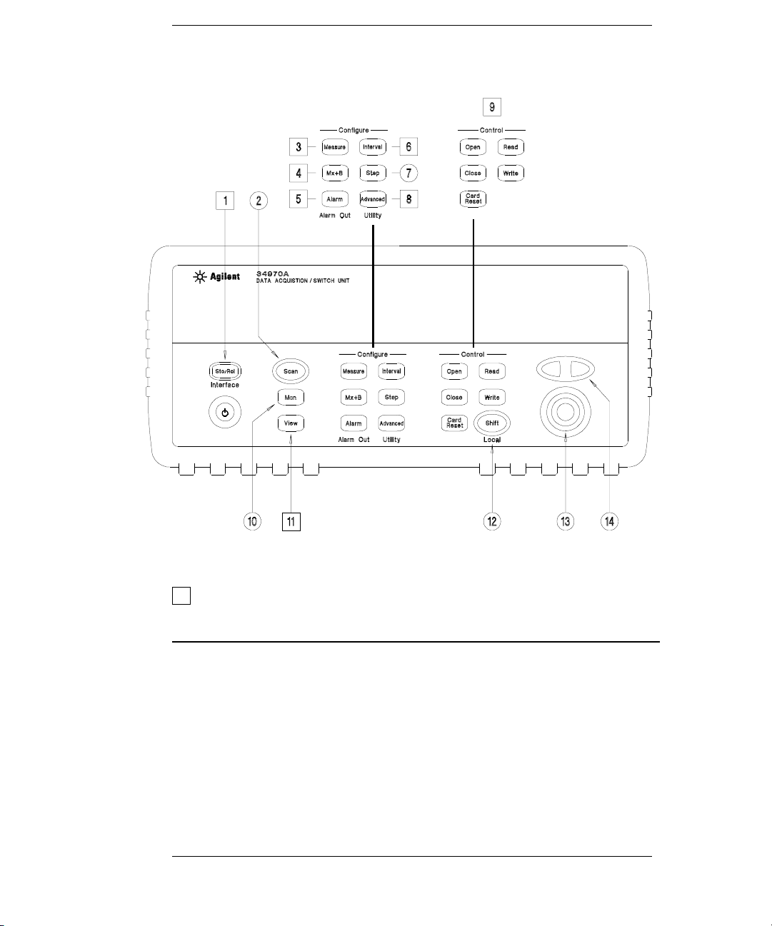
The Front Panel at a Glance
Denotes a menu key. See the next page for details on menu operation.
1 State Storage / Remote Interface Menus
2 Scan Start / Stop Key
3 Measurement Configuration Menu
4 Scaling Configuration Menu
5 Alarm / Alarm Output Configuration Menu
6 Scan-to-Scan Interval Menu
7 Scan List Single Step / Read Key
8 Advanced Measurement / Utility Menus
9 Low-Level Module Control Keys
10 Single-Channel Monitor On / Off Key
11 View Scanned Data, Alarms, Errors Menu
12 Shift / Local Key
13 Knob
14 Navigation Arrow Keys
2
Page 5
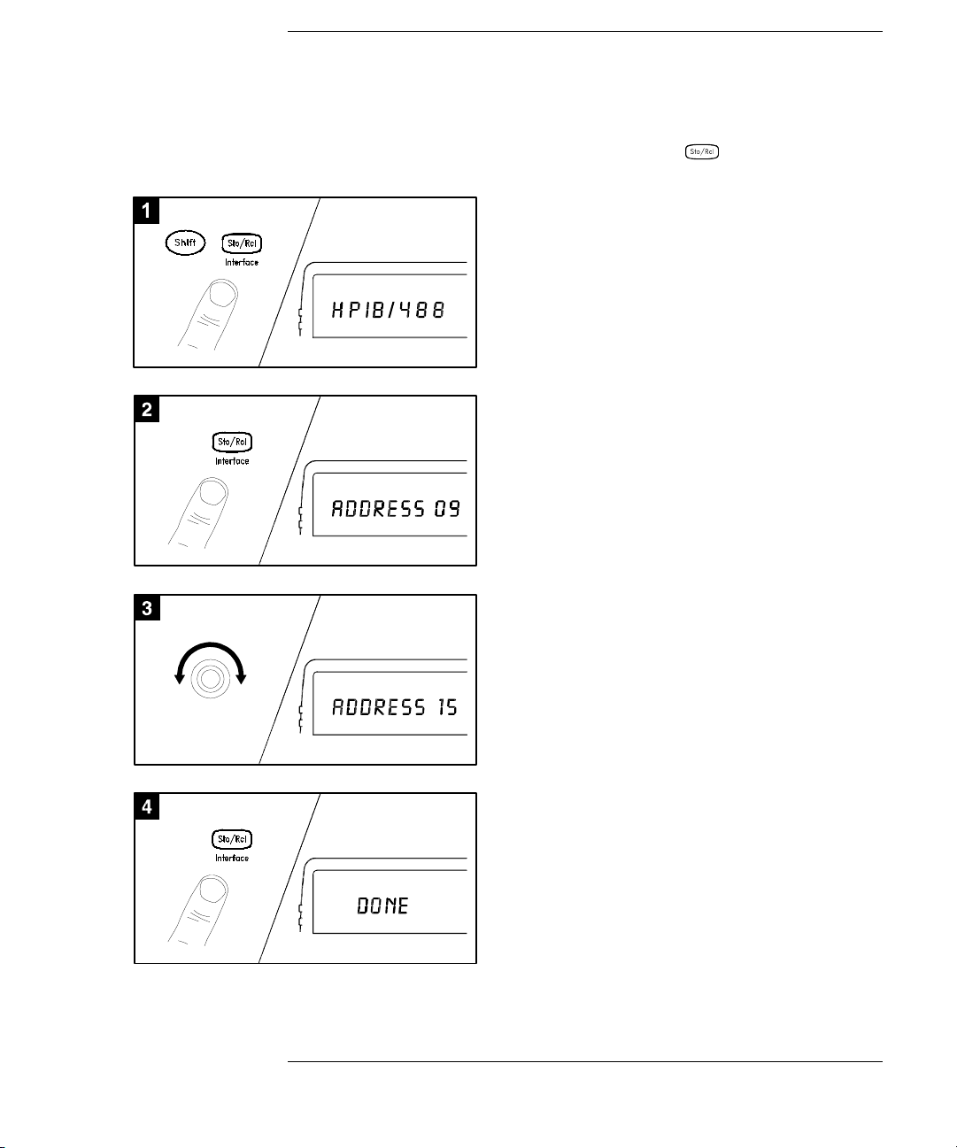
The Front-Panel Menus at a Glance
Several of the front-panel keys guide you through menus to configu re
various parameters of the instrument (see previous page). The following
steps demonstrate the menu structure using the key.
1 Press the menu key. You are automaticall y
guided to the first level of the menu.
Rotate the knob to view the other choices
on the first level of the menu.
The menu will automatically timeout after
about 20 seconds of inactivity. You will be
returned to the operation in progress prior
to entering the menu.
2 Press the same menu key again to move
to the next item of the menu. Typically,
this is where you choose parameter values
for the selected operation.
3 Rotate the knob to view the choices on this
level of the menu. When you reach the end
of the list, rotate the knob in the opposite
direction to view all of the other choices.
The current selection is highlighted for emphasis.
All other choices are dimmed.
4 Press the same menu key again to accept the
change and exit the menu. A brief confirmation
message is displayed.
Tip: To review the current configuration of a specific menu, press the menu key several times.
A message
NO CHANGES is displayed when you exit the menu.
3
Page 6
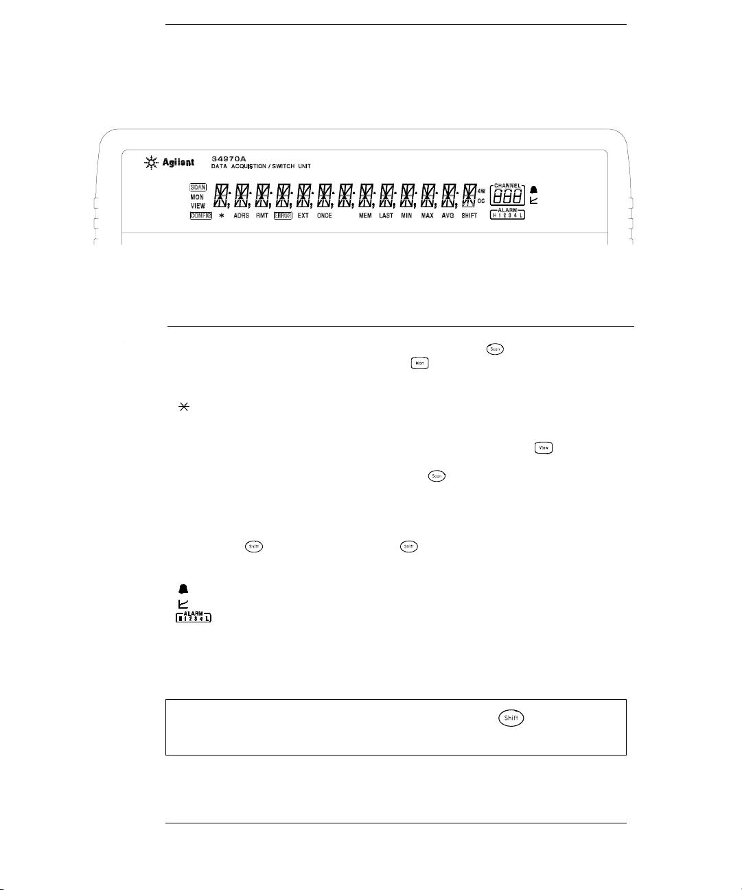
Display Annunciators
SCAN
MON
VIEW
CONFIG
ADRS
RMT
ERROR
EXT
ONCE
MEM
LAST
MIN
MAX
SHIFT
4W
OC
Scan is in progress or enabled. Press and hold again to turn off.
Monitor mode is enabled. Press again to turn off.
Scanned readings, alarms, errors, or relay cycles are being viewed.
Channel configuration is in progress on displayed channel.
Measurement is in progress.
Instrument is addressed to listen or talk over the remote interface.
Instrument is in remote mode (remote interface).
Hardware or remote interface errors are detected. Press to read errors.
Instrument is configured for an external scan interval.
Scan Once mode is enabled. Press to initiate and hold key to disable.
Reading memory overflow; new readings will overwrite the oldest readings.
Viewed data is the last reading stored during most recent scan.
Viewed data is the minimum reading stored during most recent scan.
Viewed data is the maximum reading stored during most recent scan.
has been pressed. Press again to turn off.
4-wire function is in use on displayed channel.
Offset compensation is enabled on displayed channel.
Alarms are enabled on displayed channel.
Mx+B scaling is enabled on displayed channel.
HI or LO alarm condition has occurred on indicated alarms.
To review the display annun ciators, hold down the key as you
turn on the instrument.
4
Page 7
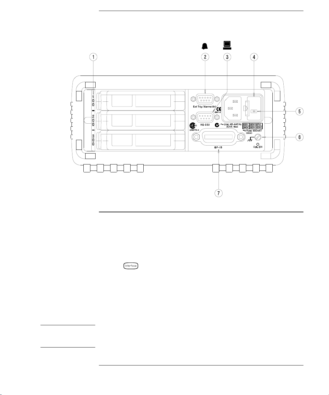
The Rear Panel at a Glance
WARNING
1 Slot Identifier (100, 200, 300)
2 Ext Trig Input / Alarm Outputs / Channel
Advance Input / Channel Closed Output
(for pinouts, see pages 83 and 128)
3 RS-232 Interface Connector
Use the Menu to:
• Select the GP-IB or RS-232 interface (see chapter 2).
• Set the GP-IB address (see chapter 2).
• Set the RS-232 baud rate, parity, and flow control mode (see chapter 2).
4 Power-Line Fuse-Holder Assembly
5 Power-Line Voltage Setting
6 Chassis Ground Screw
7 GP-IB (IEEE-488) Interface Connector
For protection from electrical shock, the power cord ground must not be
defeated. If only a two-contact electrical outlet is available, connect the
instrument’s chassis ground screw (see above) to a good earth ground.
5
Page 8

BenchLink Data Logger Software at a Glance
Agilent BenchLink Data Logger is a Windows-based application
designed to make it easy to use the 34970A with your
and analyzing measurements. Use the software to set up your test,
acquire and archive measurement data, and perform real-time display
and analysis of your incoming measurements.
BenchLink Data Logger’s key functions include the following:
• Configure measurements on the spreadsheet-like Scan Setup page.
• Display measurements graphically using the real-time Data Grid,
Strip Chart, Readout, Bar Meter, XY Plot, and Histogram wind ows.
• Add or configure graphics at any time.
• Use graphical controls to set output voltages, close channels, output
digital values, or view alarms.
• Copy measurement data and graphics to a file or to the Clipboard for
use in other applications.
• Add textual annotation and explanations to measurement results and
test reports.
• Track readings on a single channel through the Monitor toolbar.
• Enter information into the Event Log automatically or manually
while acquiring measurement data or during post-scan analysis.
• Print scan setups, event logs, and graphics.
• Communicate with the instrument using GPIB, RS-232, modem,
or LAN (using a LAN-to-GPIB gateway).
PC for gathering
To install the software, refer to “Installing BenchLink Data Logger
Software” on page 18.
To learn more about the software and its capabilities, refer to the
On-Line Help System for BenchL ink Data Logger.
6
Page 9
The Plug-In Modules at a Glance
For complete s pecifications on each plug-in module, refer to the module
sections in chapter 9.
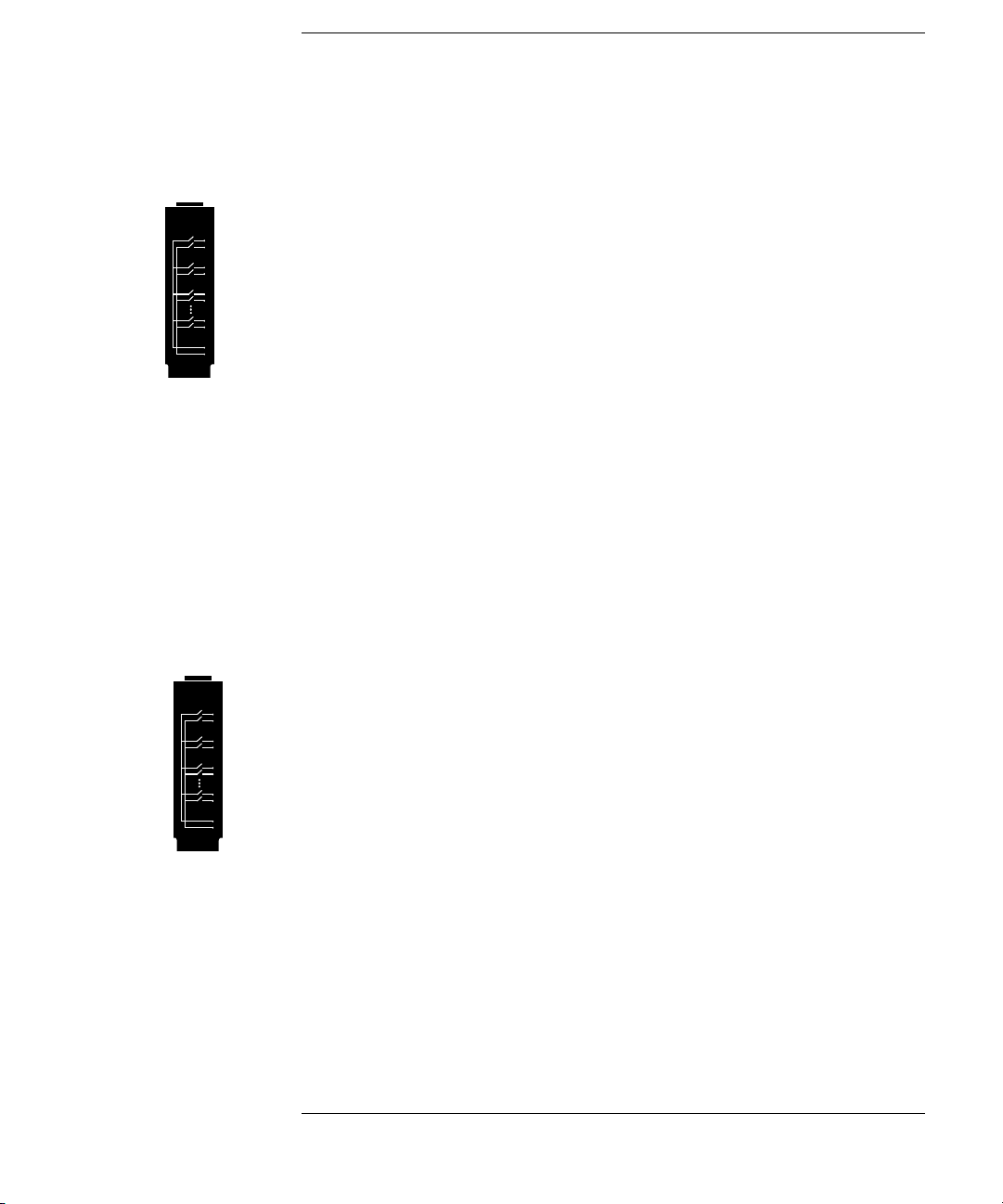
34901A 20-Channel Armature Mu ltip le xer
• 20 channels of 300 V switching
• Two channels for DC or AC current measurements (100 nA to 1A)
• Built-in thermocouple reference junction
• Switching speed of up to 60 channels per second
• Connects to the internal multimeter
• For detailed information and a module diagram, see page 164.
Each of the 20 channels switches both
fully isolated inputs to the internal multimeter. The module is divided
into two banks of 10 two-wire channels each. When making four-wire
resistance measurements, channels from Bank A are automatically
paired with channels from Bank B. Two additional fused channels are
included on the module (22 channels total) for making calibrated
AC current measurements with the internal multimeter (external shunt
resistors are not required). You can close multiple channels on this
module only if you have not configured any channels to be part of the
scan list. Otherwise, all channels on the module are break-before-make.
HI and LO inputs, thus providing
DC or
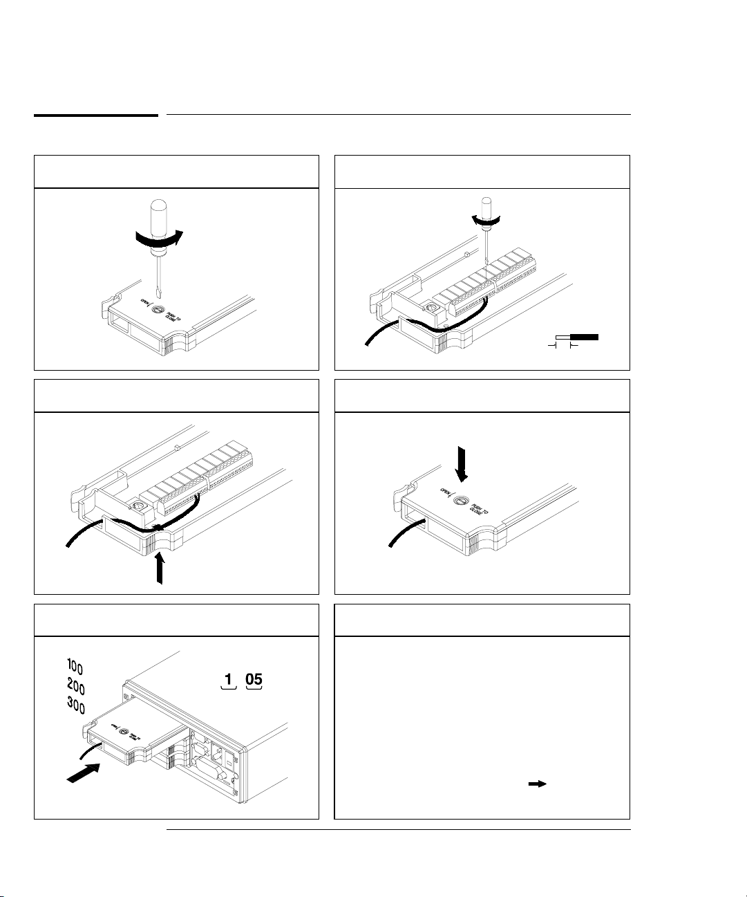
34902A 16-Channel Reed Mult iple xer
• 16 channels of 300 V switching
• Built-in thermocouple reference junction
• Switching speed of up to 250 channels per second
• Connects to the internal multimeter
• For detailed information and a module diagram, see page 166.
Use this module for high-speed scanning and high-throughput
automated test applications. Each of the 16 channels switches both
HI and LO inputs, thus providing fully isolated inputs to the internal
multimeter. The module is divided into two banks of eight two-wire
channels each. When making four-wire resistance measurements,
channels from Bank A are automatically paired with channels from
Bank B. You ca n cl ose mu lt ipl e c ha nn els on t h is modul e only if you have
not configured any channels to be part of the scan list. Otherwi se, all
channels on the module are break-before-make.
7
Page 10

34903A 20-Channel Actuator / G eneral-Purpose Switch
• 300 V, 1 A actuation and switching
• SPDT (Form C) latching relays
• Breadboard area for custom circuits
• For detailed information and a module diagram, see page 168.
Use this module for those applications that require high-integrity
contacts or quality connections of non-multiplexed signals. This module
can switch 300 V, 1 A (50 W maximum switch power) to your device
under test or to actuate external devices. Screw terminals on the module
provide access to the Normally-Open, Normally-Closed, and Common
contacts for each of the 20 switches. A breadboard area is provided near
the screw terminals to implement custom circuitry, such as simple
filters, snubbers, or voltage dividers.
34904A 4x8 Two-Wire Matri x S witch
• 32 two-wire crosspoints
• Any combination of inputs and outputs can be connected at a time
• 300 V, 1 A switching
• For detailed information and a module diagram, see page 170.
Use this module to connect multiple instruments to multiple points on
your device under test at the same time. You can connect rows and
columns between multiple modules to build larger matrices such as
8x8 and 4x16, with up to 96 crosspoints in a single mainframe.
34905/6A Dual 4-Channel RF Multiplexers
• 34905A (50Ω) / 34906A (75Ω)
• 2 GHz bandwidth with on-board SMB connections
• 1 GHz bandwidth with SMB-to-BNC adapter cables provided
• For detailed information and a module diagram, see page 172.
These modules offer wideband switching capabilities for high frequency
and pulsed signals. Each module is organized in two independent banks
of 4-to-1 multiplexers. Both modules offer low crosstalk and excellent
insertion loss performance. To create larger
cascade multiple banks together. Only one channel in each bank may be
closed at a time.
8
RF multiplexers, you can
Page 11

34907A Multifunction Module
• Two 8-bit Digital Input/Output ports, 400 mA sink, 42 V open collector
• 100 kHz Totalize input with 1 Vpp sensitivity
• Two ±12 V Calibrated Analog Outputs
• For detailed information and module block diagrams, see page 174.
Use this module to sense status and control external devices such as
solenoids, power relays, and microwave switches. For greater flexibility,
you can read digital inputs and the count on the totalizer during a scan.
34908A 40-Channel Single- End ed Mu ltip le xer
• 40 channels of 300 V single-ended (common LO) switching
• Built-in thermocouple reference junction
• Switching speed of up to 60 channels per second
• Connects to the internal multimeter
• For detailed information and a module diagram, see page 176.
Use this module for high-density switching applications which require
single-wire inputs with a common
to ensure that only one relay is connected at any time.
LO. All relays are break-before-make
9
Page 12

In This Book
Quick Start Chapter 1 helps you get familiar with a few of the
instrument’s front-panel features. This chapter also shows how to
install the BenchLink Data Logger software.
Front-Panel Overview Chapter 2 introduces you to the front-panel
menus and describes some of the instrument’s menu features.
System Overview Chapter 3 gives an overview of a data acquisition
system and describes how parts of a sy stem work together.
Features and Functions Chapter 4 gives a detailed description of the
instrument’s capabilities and operation. You will find this chapter
useful whether you are operating the instrument from the front panel or
over the remote interface.
Remote Interface Reference Chapter 5 contains reference
information to help you program the instrument over the remote
interface using the
Error Messages Chapter 6 lists the error messages that may appear
as you are working with the instrument. Each listing contains enough
information to help you diagnose and solve the problem.
SCPI language.
Application Programs Chapter 7 contains several remote interface
program examples to help you develop programs for your application.
Tutorial Chapter 8 discusses measurement considerations and
techniques to help you obtain the best accuracies and reduce sources of
measurement noise.
Specifications Chapter 9 lists the technical specifications for the
mainframe and plug-in modules.
If you have questions relating to the operation of the 34970A,
call 1-800-452-4844 in the United States, or contact your nearest
Agilent Technologies Sales Office.
If your 34970A fails within three year s of original purchase, Agile nt will
either repair or replac e it free of charge. C all 1-877-447-7278 and ask
for “Express Exchange” or contact your local Agilent office.
10
Page 13

Contents
Chapter 1 Quick Start
To Prepare the Instrument for Use 17
Installing BenchLink Data Logger Software 18
To Connect Wiring to a Module 20
To Set the Time and Date 22
To Configure a Channel for Scanning 23
To Copy a Channel Configuration 25
To Close a Channel 26
If the Instrument Does Not Turn On 27
To Adjust the Carrying Handle 29
To Rack Mount the Instrument 30
Chapter 2 Front-Panel Overview
Front-Pa nel Menu Reference 35
To Monitor a Single Ch an ne l 37
To Set a Scan Interval 38
To Apply Mx+B Scaling to Measurements 39
To Configure Alarm Limits 40
To Read a Digital Input Port 42
To Write to a Digital Output Port 43
To Read the Totalizer Count 44
To Output a DC Voltage 45
To Configure the Remote Interface 46
To Store the Instr u me nt S tat e 48
Chapter 3 System Overv iew
Data Acquisition System Overview 50
Signal Routing and Switching 57
Measurement Input 60
Control Output 67
Contents
11
Page 14

Contents
Contents
Chapter 4 Features and Functions
SCPI Language Conventions 73
Scanning 74
Single-Channel Monit oring 93
Scanning With Extern al Ins tr um ent s 95
General Measurement Configuration 98
Temperature Measurement Configuration 106
Voltage Measurement Configuration 113
Resistance Meas ure me nt Con f iguration 115
Current Measurement Configuration 116
Frequency Measure ment Configuration 118
Mx+B Scaling 119
Alarm Limits 122
Digital Input Operations 133
Totalizer Operations 135
Digital Output Operations 138
DAC Output Operations 139
System-Related Operations 140
Remote Interface Configuration 150
Calibration Overview 155
Factory Reset State 160
Instrument Pr es et S tat e 161
Multiplexer Module Default Settings 162
Module Overvi ew 163
34901A 20-Channe l Mu lti p le xer 164
34902A 16-Channe l Mu lti p le xer 166
34903A 20-Channe l Ac tuator 168
34904A 4x8 Matrix Sw it ch 170
34905A/6A Dual 4-Channel RF Multiplexers 172
34907A Multifunction Module 174
34908A 40-Channel Sin g le -Ende d Mul t ipl exe r 176
12
Page 15

Contents
Chapter 5 Remote Interface Reference
SCPI Command Summary 181
Simplified Programming Overview 201
The MEASure? and CONFigure Commands 207
Setting the Function, Range, and Resolution 214
Temperature Configuration Commands 219
Voltage Configuration Commands 223
Resistance Configuration Commands 224
Current Configuration Commands 224
Frequency Configuration Commands 225
Scanning Over v i ew 226
Single-Channel Monitori ng Overview 237
Scanning With an Externa l In str u me nt 239
Mx+B Scaling Overview 244
Alarm System O v er v i ew 247
Digital Input Commands 255
Totalizer Commands 256
Digital Output Commands 258
DAC Output Commands 2 58
Switch Control Commands 259
State Storage Commands 261
System-Related Commands 264
Interface Configuration Commands 269
RS-232 Interface Configuration 270
Modem Communications 274
The SCPI Status System 275
Status System Comma nds 286
Calibration Commands 292
Service-Related Commands 294
An Introduction to the SCPI Language 296
Using Device Clear 302
Contents
Chapter 6 Error Messages
Execution Errors 305
Instrument Errors 309
Self-Test Errors 314
Calibration Errors 315
Plug-In Module Errors 317
13
Page 16

Contents
Contents
Chapter 7 A ppl ic ation Programs
Example Programs for Excel 7.0 321
Example Programs for C and C++ 328
Chapter 8 Tuto rial
System Cabling and Connections 335
Measurement Fundamentals 343
Low-Level Signal Multiplexing 378
Actuators and G en er a l-P u r p os e S w it ching 384
Matrix Switch ing 388
RF Signal Multiplexing 390
Multifunction Mo d ul e 392
Relay Life and Preventative Maintenance 399
Chapter 9 Specifi cations
DC, Resistance, and Temperature Accuracy Specifications 404
DC Measurement and Operating Charact eristics 405
AC Accuracy Specifications 406
AC Measurement and Operating Cha racteristics 407
Measurement Rate s an d Sys t em Char a c ter i sti c s 408
Module Specifications 409
BenchLink Data Logger Software Specifications 412
Product and Module Dimensions 413
To Calculate Total Measurement Error 414
Interpreting Internal DMM Specifications 416
Configuring for Highest Accuracy Measurements 419
Index
14
Page 17

1
1
Quick Start
Page 18

Quick Start
One of the first things you will want to do with your instrument is to
become acquainted with the front panel. We have written the exercises
in this chapter to prepare the instrument for use and help you get
familiar with some of its front-panel operations.
The front panel has several groups of keys to select various functions
and operations. A few keys have a shifted function printed in blue below
the key. To perform a shifted function, press (the
will turn on). Then, press the key that has the desired label below it.
For example, to select the Utility Menu, press .
SHIFT annunciator
If you accidentally press , just press it again to turn off the
annunciator.
This chapter is divided into the following sections:
• To Prepare the Instrume nt for Use, on page 17
• Installing BenchLink Data Logger Software, on page 18
• To Connect Wiring to a Module, on page 20
• To Set the Time and Date, on page 22
• To Configure a Channel for Scanning, on page 23
• To Copy a Channel Configuration, on page 25
• To Close a Ch annel, on page 26
• If the Instrument Does Not Turn On, on page 27
• To Adjust the Carrying Handle, on page 29
• To Rack Mount the Instrument, on page 30
SHIFT
16
Page 19

Chapter 1 Quick Start
To Prepare the Instrument for Use
To Prepare the Instrument for Use
1 Check the list of supplied items.
Verify that you have received the following items with your instrument.
If anything is missing, contact your nearest Agilent Technologies Sales Office.
One power cord.
This User’s Guide.
One Service Guide.
One Quick Reference Guide.
Certificate of Calibration (if you ordered the internal DMM).
Quick Start Package (if you ordered the internal DMM):
• One RS-232 cable.
• BenchLink Data Logger Software CD-ROM.
To install the software, see page 18.
• One J-type thermocouple and a flatblade screwdriver.
Any plug-in modules that you ordered are delivered in a separate
shipping container.
1
On/Standby
Switch
WARNING
Note that this switch
Standby only.
is
To disconnect t he
mains from the
instrumen t, remove
the power cord.
2 Connect the power cord and turn on the instrument.
The front-panel display will light up briefly while the instrument
performs its power-on self-test. The
GPIB address is also displayed.
The instrument initially powers up with all measurement channels
turned off. To review the power-on display with all annunciators
turned on, hold down as you turn on the instrument. If the
instrument does not turn on properly, see p age 27.
3Perform a complete self-test.
The complete self-test performs a more extensive set of tests than those
performed at power-on. Hold down as you turn on the instrument
and hold down the ke y until you hear a long beep. The self-test will begin
when you release the key following the beep.
If the self-test fails, see the 34970A Se rvice Guide for instructions on
returning the instrument to Agilent for service.
17
Page 20

Chapter 1 Quick Start
Installing BenchLink Data Logger Software
Installing BenchLink Data Logger Software
If you ordered the 34970A with the internal DMM, then the BenchLink
Data Logger software is included. The software is shipped on one
CD-ROM, but includes a utility to build installation floppy disks.
To install the software on your
of free disk space.
For system requirements and additional details on the features of the
software, refer to the specifications in chapter 9.
Installation Procedure
PC, you will need a minimum of 12 MB
If you are running Windows 95 or Windows NT 4.0
®
1. Insert the CD-ROM into your drive.
2. Select
the
3. Select the
sheet. Click on
If you are running Windows
1. Insert the
2. Select
3. Type <drive>
CD-ROM drive. Click OK to continue and follow the on-screen
Settings | Control Panel from the Start menu. Double-click on
Add/Remove Programs icon.
Install/Uninstall tab on the Add/Remove Programs property
Install and follow the on-screen instructions.
®
3.1
CD-ROM into your drive.
File | Run from the Program Manager menu bar.
:\setup, where drive is the letter representing your
instructions.
18
Page 21

Chapter 1 Quick Start
Installing BenchLink Data Logger Software
Creating Installation Floppy Disks
You have the option to create an installation on floppy disks from the
CD-ROM installation utility. This utility is provided so that you can
install BenchLink Data Logger on a computer that does not have a
CD-ROM drive.
Note: You will need a total of five (5) formatted floppy disks to create
an installation.
1
1. Go to a computer that is equipped with a
2. Start the installation procedur e as described on the previous page.
3. Select
procedures and follow the on-screen instructions.
Create disks... on the initial display of the installation
CD-ROM drive.
On-Line Help System
The software is shipped with an extensive on-line Help system to help
you learn the features of the software as well as troubleshoot any
problems that might arise as you are using t he software. As you are
installing the software, you will notice that the on-line Help system is
available in several languages.
19
Page 22
Chapter 1 Quick Start
To Connect Wiring to a Module
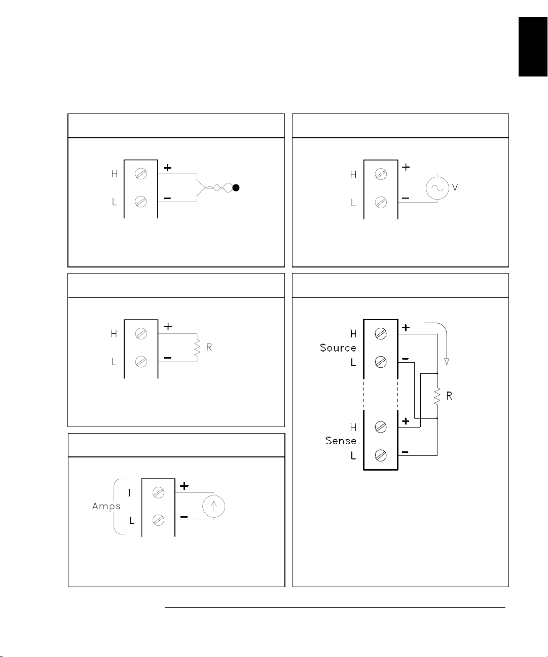
To Connect Wiring to a Module
1 Remove the module cover.
3 Route wiring through strain relief.
2 Connect wiring to the screw terminals.
20 AWG
Typical
6 mm
4 Replace the module cover.
Cable Tie Wrap
(optional)
5 Install the module into mainframe.
Channel Number:
Slot Channel
20
Wiring Hints...
• For detailed informat io n on eac h mo du le ,
refer to the section starting on page 16 3.
• To reduce wear on the internal DMM relays,
wire like functions on adjacent chan ne ls .
• For information on grounding and shielding,
see page 335.
• The diagrams on the next page show how to
connect wiring to a mult ip le xe r mod ul e fo r
each measurement function.
Page 23
Chapter 1 Quick Start
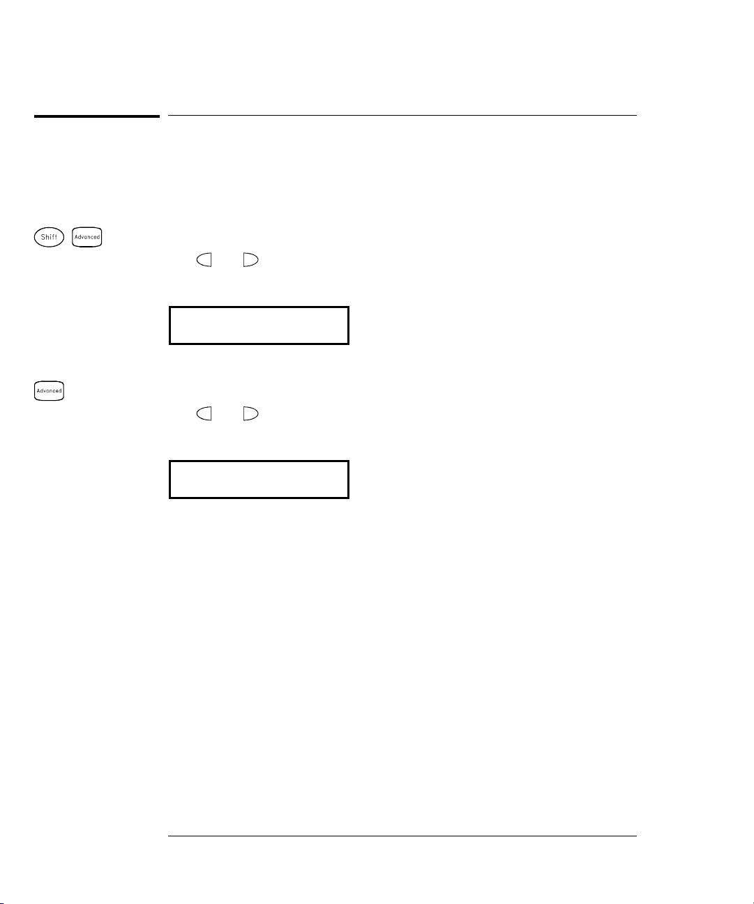
To Connect Wiring to a Module
DC Voltage / AC Voltage / Frequency Thermocouple
1
Thermocouple Types: B, E, J, K, N, R, S, T
See page 351 for thermocouple color codes.
Ranges: 100, 1 k, 10 k, 100 k, 1 M, 10 M, 100 MΩ
RTD Types: 0.00385, 0.00391
Thermistor Types: 2.2 k, 5 k, 10 k
DC Current / AC Current
Ranges: 100 mV, 1 V, 10 V, 100 V, 300 V
4-Wire Ohms / RTD 2-Wire Ohms / RTD / Thermistor
Channel n (source) is automatically paired with
Channel n+10 (sense) on the 34901A or
Channel n+8 (sense) on the 34902A.
Valid only on channels 21 and 22 on the 34901A.
Ranges: 10 mA, 100 mA, 1A
Ranges: 100, 1 k, 10 k, 100 k, 1 M, 10 M, 100 MΩ
RTD Types: 0.00385, 0.00391
21
Page 24
Chapter 1 Quick Start
To Set the Time and Date
To Set the Time and Date
All readings during a scan are automatically time stamped and stored
in non-volatile memory. In addition, alarm data is time stamped and
stored in a separate non-volatile memory queue.
Utility
Utility
1 Set the time of day.
Use and to select the field to modify and turn the knob to change
the value. You can also edit the
AM/PM field.
7,0(30
2 Set the date.
Use and to select the field to modify and turn the knob to change
the value.
-81
22
Page 25

Chapter 1 Quick Start
To Configure a Channel for Scanning
To Configure a Channel for Scanning
Any channel that can be “read” by the instrument can also be included
in a scan. This includes readings on multiplexer channels, a read of a
digital port, or a read of the count on a totalizer channel. Automated
scanning is not allowed with the
digital output, or voltage output (
1 Select the channel to be added to the sc an list.
Turn the knob until the desired channel is shown on the right side of
front-panel display. The channel number is a three-digit number;
the left-most digit represents the slot number (100, 200, or 300) and the
two digits on the right indicate the channel number (102, 110, etc.).
Note: You can use and to skip to the beginning of the previous
or next slot.
For this example, assume that you have the 34901A multiplexer
installed in slot 100 and select channel 103.
RF multiplexer, matrix, actuator,
DAC) modules.
1
2 Select the measurement parameters for the selected channel.
Use the knob to scroll through the measurement choices on each level
of the menu. When you press to make your selection, the menu
automatically guides you through all relevant choices to configure a
measurement on the selected function. When you have finished
configuring the parameters, you are automatically exited from the menu.
The current selection (or default) is displayed in full bright for easy
identification. When you make a different selection, the new choice is
shown in full bright and it becomes the default selection. The order of
the choices always remains the same; however, you always enter the
menu at the current (full bright) setting for each parameter.
Note: The menu will timeout after about 20 seconds of inactivity and
any changes made previously will take effect.
For this example, con fi gur e ch a nne l 103 to mea sur e a J -type therm oc ouple
with 0.1
°C of display resolution.
23
Page 26
Chapter 1 Quick Start
To Configure a Channel for Scanning
Note: Press to sequentially step through the scan list and take a
measurement on each channel (readings are not stored in memory).
This is an easy way to verify your wiring connections before initiating
the scan.
3 Run the scan and stor e the re ad ing s i n non- vo l at ile memo ry.
The instrument automatically scans the configured channels in
consecutive order from slot 100 through slot 300 (the
SCAN annunciator
turns on). Channels that are not configured are skipped during the scan.
In the default configuration, the instrument continuously scans the
configured channels at a 10-second interval.
Press and hold to stop the scan.
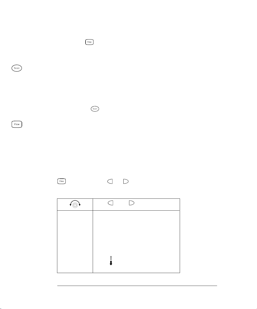
4 View the data f rom t he scan.
All readings taken during a scan are automatically time stamped and
stored in non-volatile memory. During the scan, the instrument
calculates and stores the minimum, maximum, and average on all
channels in the scan list. You can read the contents of memory at any
time, even during a scan.
From the front panel, data is available for the last 100 readings on each
channel readings taken during a scan (all of the data is available from
the remote interface). From the View menu, select
READINGS and press
again. Then press and to choose the data you want to view
for the selected channel as shown in the table below.
and
Select Channel Last Reading on Channel
Time of Last Reading
Minimum Reading on Channel
Time of Minimum Reading
Maximum Reading on Channel
Time of Maximum Reading
Average of Readings on Channel
Second Most Recent Reading on Channel
Third Most Recent Reading on Channel
99th Most Recent Reading on Channel
24
Page 27

Chapter 1 Quick Start
To Copy a Channel Configuration
To Copy a Channel Configuration
After configuring a channel to be included in the scan list, you can
copy that same configuration to other channels in the instrument
(including digital channels on the multifunction module). This feature
makes it easy to configure several channels for the same measurement.
When you copy the configuration from one channel to another, the
following parameters are automatically copied to the new channel:
• Measurement configuration
• Mx+B scaling configuration
• Alarm configuration
• Advanced measurement configuration
1 Select the channel to copy the conf ig uratio n from.
Turn the knob until the desired channel is shown on the right side of
front-panel display. For this example, let’s copy the configuration from
channel 103.
1
2 Select the copy function.
Use the knob to scroll through the measurement choices until you see
COPY CONFIG. When you press to make your selection, the menu
automatically guides you to the next step.
3 Select the channel to copy the conf ig uratio n to.
Turn the knob until the desired channel is shown on the right side of
front-panel display. For this example, let’s copy the configuration to
channel 105.
3$67(72
4 Copy the channel configuration to the selected cha nnel.
Note: To copy the same configuration to other channels, repeat this procedure.
25
Page 28
Chapter 1 Quick Start
To Close a Channel
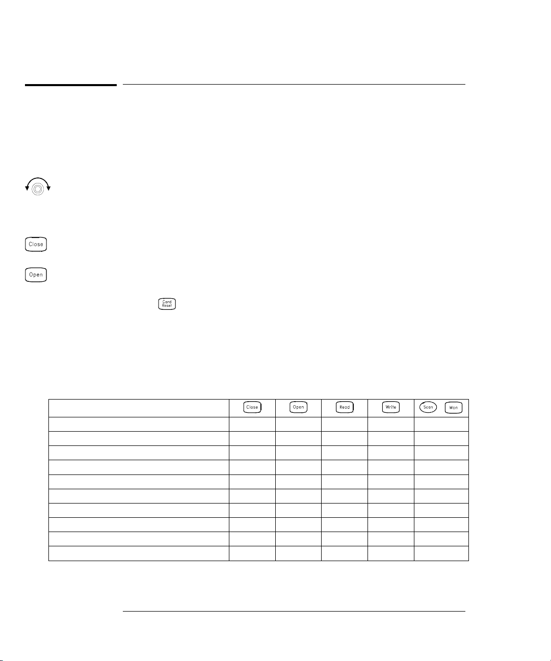
To Close a Channel
On the multiplexer and switch modules, you can close and open individual
relays on the module. However, note that if you have already configured
any multiplexer channels for scanning, you cannot independently close
and open individual relays on that module.
1 Select the channel.
Turn the knob until the desired channel is shown on the right side of
front-panel display. For this example, select channel 213.
2 Close the selected channel.
3 Open the selected channel.
Note: will sequentially open all channels on the module in the
selected slot.
The table below shows the low-level control operations available for
each of the plug-in modules.
Plug-In Module
34901A 20-Channel Mux
34902A 16-Channel Mux
34908A 40-Channel Single-Ended Mux
34903A 20-Channel Actuator
34904A 4x8 Matrix
34905A Dual 4-Channel RF Mux (50Ω)
34906A Dual 4-Channel RF Mux (75
34907A Multifun ction Module (DIO)
34907A Multifunction Module (Totalizer)
34907A Multifunction Module (DAC)
[1] Only one channel can be closed at a time on this module.
[2] Only one channel in each bank can be closed at a time on this module.
Ω)
26
,
•••
[1]
[2]
[2]
•••
••• •
••
••
•
•
•• •
••
•
•
•
Page 29

Chapter 1 Quick Start
If the Instrument Does Not Turn On
If the Instrument Does Not Turn On
Use the following steps to help solve problems you might encounter
when turning on the instrument. If you need more help, refer to the
34970A Service Guide for instructions on returning the instrument to
Agilent for service.
1 Verify that there is ac power to the instrument.
First, verify that the power cord is firmly plugged into the power
receptacle on the rear panel of the instrument. You should also make
sure that the power source you plugged the instrument into is
energized. Then, verify that the instrument is turned on.
The On/Standby switch is located on the lower left side of the front panel.
2 Verify the powe r -li ne voltage setting.
The line voltage is set to the proper value for your country when the
instrument is shipped from the factory. Change the voltage setting if
it is not correct. The settings are: 100, 120, 220, or 240 Vac.
1
Note: For 127 Vac operation, use the 120 Vac setting.
For 230 Vac operation, use the 220 Vac setting.
See the next page if you need to change the line voltage setting.
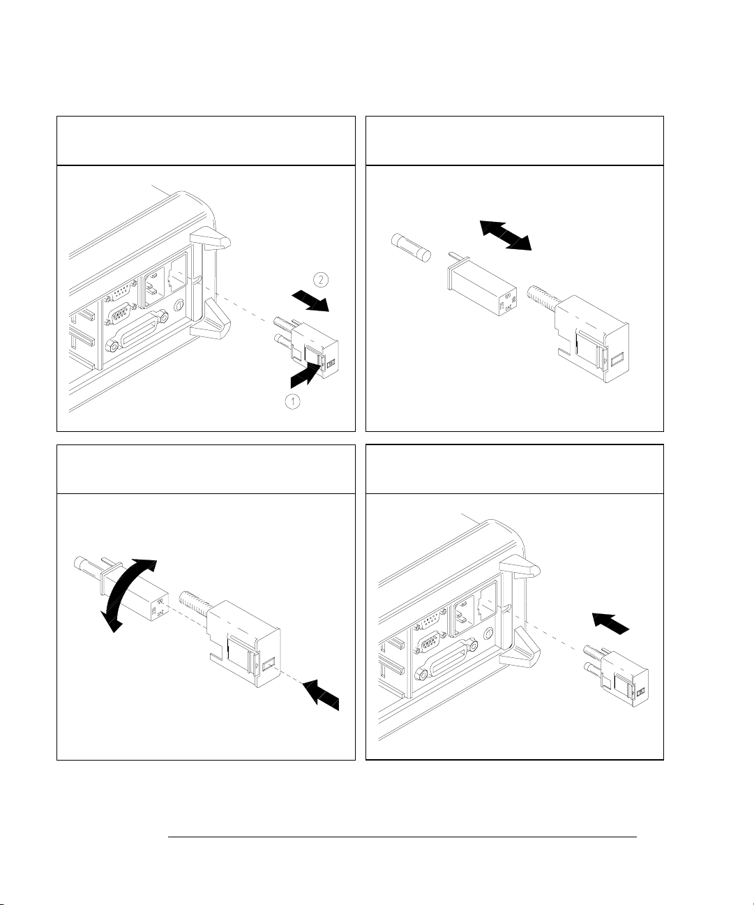
3 Verify that the po wer-line fuse is good .
The instrument is shipped fr om the fact ory with a 50 0 mA fuse inst alled.
This is the correct fuse for all line voltages.
See the next page if you need to replace the power-line fuse.
To replace the 500 mAT, 250 V fuse, order Agilent part number 2110-0458.
27
Page 30
Chapter 1 Quick Start
If the Instrument Does Not Turn On
1 Remove the power cord. Remove the
fuse-holder assembly from the rear panel.
3 Rotate the line-voltage selector until the
correct voltage appears in the window.
2 Remove the line-voltage selector from
the assembly.
Fuse: 500 mAT (for all line voltages)
Agilent Part Number: 2110-0458
4 Replace the fuse-holder assembly in
the rear panel.
100, 120 (127), 220 (230) or 240 Vac
Verify that the correct line voltage is selected and the power-line fuse is good.
28
Page 31

Chapter 1 Quick Start
To Adjust the Carrying Handle
To Adjust the Carrying Handle
To adjust the position, grasp the handle by the sides and pull outward.
Then, rotate the handle to the desired position.
1
Bench-top viewing positions Carrying position
29
Page 32

Chapter 1 Quick Start
To Rack Mount the Instrument
To Rack Mount the Instrument
You can mount the instrument in a standard 19-inch rack cabinet using
one of three optional kits available. Instructions and mounting
hardware are included with each rack-mounting kit. Any Agilent System II
instrument of the same size can be rack-mounted beside the 34970A.
Note: Remove the carrying handle, and the front and rear rubber bumpers,
before rack-mounting the instrument.
To remove the handle, rotate it to the vertical position and pull the ends outward.
Front Rear (bottom view)
To remove the rubber bumper, stretch a corner and then slide it off.
30
Page 33

Chapter 1 Quick Start
To Rack Mount the Instrument
To rack mou n t a s in gl e in strument, o r de r a da p t er ki t 5063 -9 24 0.
To rack mount two instruments side-by-side, order lock-link kit 5061-9694 and
flange kit 5063-9212. Be sure to use the support rails inside the rack cabinet.
1
To install one or two instruments in a sliding support shelf, order shelf 5063-9255,
and slide kit 1494-0015 (for a single instrument, also order filler panel 5002-3999).
31
Page 34

32
Page 35

2
2
Front-Panel
Overview
Page 36

Front-Panel Overview
This chapter introduces you to the front-panel keys and menu operation.
This chapter does not give a detailed description of every front-panel
key or menu operation. It does, however, give you a good overview of the
front-panel menu and many front-panel operations. See chapter 4
“Features and Functions,” starting on page 71, for a complete discussion
of the instrument’s capabilities and operation.
This chapter is divided into the following sections:
• Front-Panel Menu Reference, on page 35
• To Monitor a Single Channel, on page 37
• To Set a Scan Interval, on page 38
• To Apply Mx+B Scaling to Measurements, on page 39
• To Configure Alarm Limits, on page 40
• To Read a Digital Input Port, on page 42
• To Write to a Digital Output Port, on page 43
• To Read the Totalizer Count, on page 44
• To Output a DC Vo ltage, on page 45
• To Configure the Remote Interface, on page 46
• To Store the Instrument State, on page 48
34
Page 37

Chapter 2 Front-Panel Overview
Front-Panel Menu Reference
Front-Panel Menu Reference
This section gives an overview of the front-panel menus. The menus are
designed to automatically guide you through all parameters required to
configure a particular function or operation. The remainder of this
chapter shows examples of using the front-panel menus.
Configure th e measurement parameters on th e displayed channel.
• Select measure me nt function (dc volts, oh ms , et c.) on the displayed channel.
• Select transducer type for temperature measurements.
• Select units (°C, °F, or K) for temperature measurements.
• Select measureme nt rang e or au to ran ge .
• Select measureme nt resolution.
• Copy and paste measurement confi gu r at io n to other channels.
Configure the scaling parameters for the displayed channel.
• Set the gain (“M”) and offset (“B”) value for the displayed channel.
• Make a null measurement and store i t as the offset value.
• Specify a custom la be l (RPM, PSI, etc.) for the disp la ye d ch an ne l.
2
Configure al arms on the displayed channel.
• Select one of fou r ala rms to report alarm condit io ns on th e displayed channe l.
• Configure a hi gh lim it , lo w lim it , or bo th for the displayed chan ne l.
• Configure a bit pa ttern which will gene rat e an ala rm (di gi t a l in pu t on ly ).
Configure the four Alarm Outp ut ha rdw a re li ne s.
• Clear the state of the four alarm outp ut lin es .
• Select the “Latch” or “Track” mode for the four alarm output lines.
• Select the slope (ris in g or fa ll ing edge) for the four alarm out pu t li ne s.
Configure the event or action that controls the scan interval.
• Select the scan int erv al mod e (in te rva l, manual, external, or al arm ).
• Select the scan cou nt.
35
Page 38

Chapter 2 Front-Panel Overview
Front-Panel Menu Reference
Configure the advanced measurement features on displayed channel.
• Set the integration time for measurements on the displayed channel.
• Set the channel-to-channel del ay for scanning.
• Enable/disabl e th e th erm oc ou pl e ch ec k fe ature (T/C measurement s on ly ).
• Select the refere nce ju nc ti on source (T/C measureme nt s on ly ).
• Set the low frequency limit (ac measurements only).
• Enable/disable offset compensation (resistance measurements only).
• Select the binary or decimal mode for digital operations (digital input/output only).
• Configure the to ta lizer reset mode (total iz er on ly ).
• Select which edge is detected (rising or falling) for totalizer operations.
Configure system-related instrument parameters.
• Set the real-time system clock and calendar.
• Query the firmware revisions for the mainframe and installed modules.
• Select the inst rumen t ’ s pow er-o n co nf ig uration (last or factory reset).
• Enable/disable the internal DMM.
• Secure/unsecure the instrument for calibration.
View readings, alarms, and errors.
• View the last 100 sc anned readings from me mo ry (la st , min, max, and average ).
• View the first 20 alarms in the alar m queue (reading and time alarm occ urred).
• View up to 10 errors in the error queue.
• Read the number of cycles for the displayed relay (relay maintenance feature).
Store and recall in stru me nt sta tes.
• Store up to five inst rument states in non-volatile memory.
• Assign a name to ea ch storage location .
• Recall stored st ates, power-down sta te , fa ct ory rese t state, or preset sta te .
Configure the remote interface.
• Select the GPIB addre ss.
• Configure the RS -23 2 in te rfa ce (bau d rat e, pari ty , an d fl ow co ntrol).
36
Page 39

Chapter 2 Front-Panel Overview
To Monitor a Single Channel
To Monitor a Single Channel
You can use the Monitor function to continuously take readings on a si ngle
channel, even during a scan. This feature is useful for troubleshooting your
system before a test or for watching an important signal.
1 Select the channel to be monitored.
Only one channel can be monitored at a time but you can change the
channel being monitored at any time by turning the knob.
2 Enable monitoring on the selected cha nnel.
Any channel that can be “read” by the instrument can be monitored
(the
MON annunciator turns on). This includes any combination of
temperature, voltage, resistance, current, frequency, or period
measurements on multiplexer channels. You can also monitor a digital
input port or the totalizer count on the multifunction module.
2
To disable monitoring, press again.
37
Page 40

Chapter 2 Front-Panel Overview
To Set a Scan Interval
To Set a Scan Interval
You can set the instrument’s internal timer to automatically scan at a
specific interval (e.g., start a new scan sweep every 10 seconds) or when
an external
instrument to scan continuously or to stop after sweeping through the
scan list a specified number of tim es.
1 Select the interv al s c an mo de .
For this example, select the Interval Scan mode which allows you to set
the time from the start of one scan sweep to the start of the next scan
sweep. Set the interval to any value between 0 and 99 hours.
,17(59$/6&$1
2 Select the scan count.
TTL trigger pulse is received. You can configure the
You can specify the number of times that the instrument will sweep
through the scan list (the default is continuous). When the specified
number of sweeps have occurred, the scan stops. Set the scan count to
any number between 1 and 50,000 scans (or continuous).
6&$16
3 Run the scan and sto re t he r e ad ing s i n memo ry.
38
Page 41

Chapter 2 Front-Panel Overview
To Apply Mx+B Scaling to Measurements
To Apply Mx+B S caling to Measu re ments
The scaling function allows you to apply a gain and offset to all readings
on a specified multiplexer channel during a scan. In addition to setting
the gain (“M”) and offset (“B”) values, you can also specify a custom
measurement label for your scaled readings (
1 Configure the channel.
You must configure the channel (function, tra nsducer type, etc.) before
applying any scaling values. If you change the measurement
configuration, scaling is turned off on that channel and the gain and
offset values are reset (M=1 and B=0).
2 Set the gain and of f s et va l ues .
The scaling values are stored in non-volatile memory for the specified
channels. A Factory Reset turns off scaling and clears the scaling values
on all channels. An Instrument Preset or Card Reset does not clear the
scaling values and does not turn off scaling.
RPM, PSI, etc.).
2
,
,9'&
3 Select the custom label.
You can specify an optional three-character label for your scaled
readings (
unit for the selected function (
RPM, PSI, etc.). The default label is the standard engineering
Set Gain
Set Offset
VDC, OHM, etc.).
/$%(/$6/%6
4 Run the scan and stor e the s c ale d re ad ing s i n memo ry.
39
Page 42

Chapter 2 Front-Panel Overview
To Configure Alarm Limits
To Configure Alarm Limits
The instrument has four alarms which you can configure to alert you
when a reading exceeds specified limits on a channel during a scan.
You can assign a high limit, a low limit, or both to any configured
channel in the scan list. You can assign multiple channels to any of the
four available alarms (numbered 1 through 4).
1 Configure the channel.
You must configure the channel (function, tra nsducer type, etc.) before
setting any alarm limits. If you change the measurement configuration,
alarms are turned off and the limit values are cleared. If you plan to use
Mx+B scaling on a channel which will also use alarms, be sure to
configure the scaling values first.
2 Select which of the four al arms yo u want to use .
86($/$50
3 Select the alarm mode on the selected channel.
You can configure the instrument to generate an alarm when a
measurement exceeds the specified HI or LO limits (or both) on a
measurement channel.
+,$/$5021/<
40
Page 43

Chapter 2 Front-Panel Overview
To Configure Alarm Limits
4 Set the limit value.
The alarm limit values are stored in non-volatile memory for the
specified channels. The def ault val ues for the high an d low limi ts are “0”.
The low limit must always be less than or equal to the high limit, even if
you are using only one of the limits. A Factory Reset clears all alarm
limits and turns off all alarms. An Instrument Preset or Card Reset does
not clear the alarm limits and does not turn off alarms.
,°&
5 Run the scan and sto re t he r e ad ing s i n memo ry.
If an alarm occurs on a channel as it is being scanned, then that
channel’s alarm status is stored in reading memory as the readings are
taken. Each time you start a new scan, the instrument clears all
readings (including alarm data) stored in reading memory from the
previous scan. As alarms are generated, they are also logged in an
alarm queue, which is separate from reading memory. Up to 20 alarms
can be logged in the alarm queue. Reading the alarm queue using the
View menu clears the alarms in the queue.
2
41
Page 44

Chapter 2 Front-Panel Overview
To Read a Digital Input Port
To Read a Digital Input Port
The multifunction module (34907A) has two non-isolated 8-bit
input/output ports which you can use for reading digital patterns.
You can read the live status of the bits on the port or you can configure
a scan to include a digital read.
1 Select the Digital Input port.
Select the slot containing the multifunction module and continue
turning the knob until
2 Read the specified port.
You can specify whether you want to use binary or decimal format.
Once you have selected the number base, it is used for all input or
output operations on the same port. To change the number base,
press the key and select
DIN is displayed (channel 01 or 02).
USE BINARY or USE DECIMAL.
',1
Bit 7 Bit 0
The bit pattern read from the port will be displayed until you press
another key, turn the knob, or until the display times out.
Note: To add a digital input channel to a scan list, press and select
the
DIO READ choice.
42
Binary Display Shown
Page 45

Chapter 2 Front-Panel Overview
To Write to a Digital Output Port
To Write to a Digital Output Port
The multifunction module (34907A) has two non-isolated 8-bit
input/output ports which you can use for outputting digital patterns.
1 Select the Digital Output port.
Select the slot containing the multifunction module and continue
turning the knob until
2 Enter the bit pattern editor.
DIN is displayed (channel 01 or 02).
2
Notice that the port is now converted to an output port (
'287
Bit 7 Bit 0
3 Edit the bit pattern.
Use the knob and or keys to edit the individual bit values.
You can specify whether you want to use binary or decimal format.
Once you have selected the number base, it is used for all input or
output operations on the same port. To change the number base,
press the key and select
'287
4 Output the bit pattern to the specified port.
The specified bit pattern is latched on the specified port. To cancel an
output operation in progress, wait for the display to time out.
Binary Display Shown
USE BINARY or USE DECIMAL.
Decimal Display Shown
DOUT).
43
Page 46

Chapter 2 Front-Panel Overview
To Read the Totalizer Count
To Read the Totalizer Count
The multifunction module (34907A) has a 26-bit totalizer which can
count pulses at a 100 kHz rate. You can manually read the totalizer
count or you can configure a scan to read the count.
1 Select th e totalizer ch a n ne l .
Select the slot containing the multifunction module and continue
turning the knob until
2 Configure the totalize mode.
The internal count starts as soon as you turn on the instrument.
You can configure the totalizer to reset the count to “0” after being read
or it can count continuously and be manually reset.
5($'5(6(7
TOTALIZE is displayed (channel 03).
3 Read the count.
The count is read once each time you press ; the count does not
update automatically on the display. As configured in this example,
the count is automatically reset to “0” each time you read it.
727
The count will be displayed until you press another key, turn the knob,
or until the display times out. To manually reset the totalizer count,
press .
Note: To add a totalizer channel to a scan list , press and select the
TOT READ choice.
44
Page 47

Chapter 2 Front-Panel Overview
To Output a DC Volta ge
To Output a DC Voltage
The multifunction module (34907A) has two analog outputs capable of
outputting calibrated voltages between
±12 volts.
2
1Select a
Select the slot containing the multifunction module and continue
turning the knob until
2 Enter the output vo lta ge ed it or.
DAC Output channel.
DAC is displayed (channel 04 or 05).
9'$&
3 Set the desired output voltage.
Use the knob a nd or keys to edit the individual digits.
9'$&
4 Output the vol t ag e f r o m the se l ec t ed DAC.
The output voltage will be displayed until you press another key or turn
the knob. To manually reset the output voltage to 0 volts, press .
45
Page 48

Chapter 2 Front-Panel Overview
To Configure the Remote Interface
To Configure the Remote Interface
The instrument is shipped with both an GPIB (IEEE-488) interface
and an
The
the factory.
GPIB Configuration
RS-232 interface. Only one interface can be enabled at a time.
GPIB interface is selected when the instrument is shipped from
Interface
Interface
1 Select the
GPIB (HPIB) interface.
+3,%
2 Select the GPIB address.
You can set the instrument’s address to any value between 0 and 30.
The factory setting is address “9”.
$''5(66
3 Save the change and exit the menu.
Note: Your computer’s GPIB interface card has its own address.
Be sure to avoid using the computer’s address for any instrument on the
interface bus. Agilent’s GPIB interface cards generally use address “21”.
46
Page 49

Chapter 2 Front-Panel Overview
To Configure the Remote Interface
RS-232 Configuration
Interface
Interface
1 Select the RS -2 32 int erf a c e.
2
56
2 Select the baud rate.
Select one of the following: 1200, 2400, 4800, 9600, 19200, 38400,
57600 (factory setting), or 115200 baud.
%$8'
3 Select the parity and number of data bits.
Select one of the following: None (8 data bits, factory setting),
Even (7 data bits), or Odd (7 data bits). When you set the parity,
you are also indirectly setting the number of data bits.
(9(1,%,76
Interface
Interface
4 Select the flow control method.
Select one of the following: None (no flow control),
XON/XOFF (factory setting), or Modem.
)/2:'75'65
5 Save the changes and ex it the menu.
RTS/CTS, DTR/DSR,
47
Page 50

Chapter 2 Front-Panel Overview
To Store the Instrument State
To Store the Instrument State
You can store the instrument state in one o f five non-volatile storage
locations. A sixth storage location automatically holds the power-down
configuration of the instrument. When power is restored, the instrument
can automatically return to its state before power-down (a scan in
progress before power-down will also be resumed).
1 Select the storage location.
From the front panel, you have the ability to assign names (up to 12
characters) to each of the five stored states.
1$0(67$7(
7(67BUDFNB
The storage locations are numbered 1 through 5. The power-down
state is automatically stored and can be recalled from the front panel
(the state is named
LAST PWR DOWN).
6725(67$7(
67$7(
2 Store the instrument state.
The instrument stores all channel configurations, alarm values, scaling
values, scan interval setups, and advanced measurement configurations.
&+$1*(6$9('
48
Page 51

3
3
System Overview
Page 52

System Overview
This chapter provides an overview of a computer-based system and
describes the parts of a data acquisition system. This chapter is divided
into the following sections:
• Data Acquisition System Overview, see below
• Signal Routing and Switching, starting on page 57
• Measurement Input, starting on page 60
• Control Output, starting on page 67
Data Acquisition System Overview
You can use the Agilent 34970A as a stand-alone instrument but there are
many applications where you will want to take advantage of t he built-i n
connectivity features. A typical data acquisition system is shown below.
PC
Computer
and Software Interface Cable 34970A
50
Plug-in
Modules
System
Cabling
Transducers,
Sensors,
and Events
Page 53

Chapter 3 System Overview
Data Acquisition System Overview
The system configuration shown on the previous page offers the
following advantages:
• You can use the 34970A to perform data storage, data reduction,
mathematical calculations, and conversion to engineering units.
You can use the
PC to provide easy configuration and data presentati on.
• You can remove the analog signals and measurement sensors from
the noisy
PC environment and electrically isolate them from both the
PC and earth ground.
• You can use a single PC to monitor multiple instruments and
The Computer and Interface Cable
Since computers and operating systems are the subject of many books
and periodicals, they are not discussed in this chapter. In addition to the
computer and operating system, you will need a serial port (
GPIB port (IEEE-488) and an interface cable.
Serial (RS-232) GPIB (IEEE-488)
Advantages Disadvantages Advantages Disadvantages
Often built into the computer;
no additional hardware is
required.
Drivers usually included in
the operating system.
Cables readily available
and inexpensive.
The 34970A is
shipped with a serial cable
(if internal DMM is ordered).
measurement points while performing other
Cable length is limited
to 45 ft (15 m). *
Only one instrument or
device can be connected
per serial port.
Cabling is susceptible to
noise, causing slow or
lost communications.
Varying connector pinouts
and styles.
Data transfers up to
85,000 characters/sec.
Speed; faster data and
command transfers.
Additional system flexibility,
multiple instruments can
be connected to the
same GPIB port.
Direct Memory Transfers
are possible.
Data transfe r s up to
750,000 characters/sec.
PC-based tasks.
RS-232) or
Cable length is limited
to 60 ft (20 m). *
Requires an expansion
slot plug-in card in PC
and associated drivers.
Requires special cable.
3
* You can overcome these cable length limitations using spe cia l communications hardware.
For example, you can use the Agilent E5810A LAN-to-GPIB Gateway interface or a serial modem.
51
Page 54

Chapter 3 System Overview
Data Acquisition System Overview
Measurement Software
A variety of software is available to configure your data acquisition
hardware and manipulate and display your measurement data.
Data Logging and Monitoring
®
Agilent BenchLink Data Logger is a Windows
designed to make it easy to use the 34970A with your
and analyzing measurements. The software is included with the 34970A
when you order the internal
DMM. Use this software to set up your test,
acquire and archive measurement data, and perform real-time display
and analysis of your incoming measurements.
-based application
PC for gathering
Agilent BenchLink Data Logger
Automated Testing with Multiple Instrumen ts
• Agilent VEE
• TransEra HTBASIC
• National Instruments LabVIEW
• Microsoft
®
Visual Basic or Visual C++
52
®
for Windows
Page 55

Chapter 3 System Overview
Data Acquisition System Overview
The 34970A Data Acquisition / Switch Unit
As shown below, the logic circuitry for the 34970A is divided into two
sections: earth-referenced and floating. These two sections are isolated
from each other in order to maintain measurement accuracy and
repeatability (for more information on ground loops, see page 341).
External Trigger
OUT
IN
Alarms
To Computer
Optional
Digital
Bus
Internal
DMM
Analog Bus
100
200
300
Control
GPIB
RS-232
AC Power
Floating
Logic
Earth
Referenced
Logic
= Optical Isolators
The earth-referenced and floating circuitry communicate with each
other via an optically-isolated data link. The earth-referenced section
communicates with the floating section to provide
The instrument is shipped with both an
GPIB (IEEE-488) interface
PC connectivity.
and an RS-232 interface. Only one interface can be enabled at a time.
The earth-referenced section also provides four hardware alarm outputs
and external trigger lines. You can use the alarm output lines to trigger
external alarm lights, sirens, or send a
TTL pulse to your control system.
3
Plug-In
Slots
The floating section contains the main system processor and controls all
of the basic functionality of the instrument. Thi s is where the instrument
communicates with the plug-in modules, scans the keyboard, controls the
front-panel display, and controls the internal
DMM. The floating section
also performs Mx+B scaling, monitors alarm conditions, converts
transducer measurements to engineering units, time stamps scanned
measurements, and stores data in non-volatile memory.
53
Page 56

Chapter 3 System Overview
Data Acquisition System Overview
Plug-In Modules
The 34970A offers a complete selection of plug-in modules to give you
high-quality measurement, switching, and control capabilities.
The plug-in modules communicate with the floating logic via the internal
isolated digital bus. The multiplexer modules also connect to the
internal
microprocessor to offload the mainframe processor and minimize
backplane communications for faster throughput. The table below shows
some common uses for eac h plug-in module.
For more information on each module, refer to the module sections in
chapter 4, starting on page 163.
Model Number Module Name Common Uses
34901A 20-Channel Mux with T/C
34902A 16-Channel Reed Mux with T/C
34908A 40-Channel Single-Ended Mux
34907A Multifunction Module Digital Input, Event Counting.
34901A 20-Channel Mux with T/C
34902A 16-Channel Reed Mux with T/C
34908A 40-Channel Single-Ended Mux
34904A 4x8 Matrix Switch 32 Crosspoint Matrix switching.
34905A
34906A
34903A 20-Channel Actuator General-purpose switching and control
34907A Multifunction Module Digital Output, Voltage (DAC) Outputs.
DMM via the internal analog bus. Each module has its own
Measurement Input
Compensation
Compensation
with T/C Compensation
Signal Routing
Compensation
Compensation
with T/C Compensation
Dual 4-Channel RF Mux (50
Dual 4-Channel RF Mux (75
Control Output
Scanning and direct measurement of
temperature, voltage, resistance, frequency,
and current (34901A only) using the
internal DMM.
Scanning and direct measurement of
temperature, voltage, and resistance using
the internal DMM.
Multiplexing of signals to or from external
instruments.
50
Ω)
Ω)
Ω high-frequency applications (< 2 GHz).
75
Ω high-frequency applications (< 2 GHz).
using Form C (SPDT) switches.
54
Page 57

Chapter 3 System Overview
Data Acquisition System Overview
System Cabling
The plug-in modules have screw-terminal connectors to make it easy to
connect your system cabling. The type of cabling that you use to connect
your signals, transducers, and sensors to the module is critical to
measurement success. Some types of transducer s, such a s th ermocouples,
have very specific requirements for the type of cable that can be used to
make connections. Be sure to consider the usage environment when
choosing wire gauge and insulation qualities. Wire insulation typically
consists of materials such as
PVC or Teflon
several common cable types and describes their typical uses.
Note: Wiring insulation and usage is described in more detail in
“System Cabling and Connections” starting on page 335.
Cable Type Common Uses Comments
Thermocouple
Extension Wire
Twisted Pair,
Shielded Twisted Pair
Shielded Coaxial,
Double-Shielded
Coaxial
Flat Ribbon,
Twisted Pair Ribbon
Thermocouple measurements. Av ail a ble in s p ec ific th er mo couple types.
Measurement inputs, voltage
outputs, switching, counting.
VHF signal switching. Most common cable for high-frequency
Digital Input/Output Often used with mass termination
®
. The table below lists
Also available in a shielded cable for
added noise immunity.
Most common cable for low-frequency
measurement inputs. Twisted pair
reduces common mode noise.
Shielded-twisted pair provides additional
noise immunity.
signal routing. Available in specific
impedance values (50
Provides excellent noise immunity.
Double-shielded cable improves
isolation between channels. Requires
special connectors.
connectors. These cables provide little
noise immunity.
3
Ω or 75Ω).
Teflon is a registered trademark of E.I. duPont deNemours and Company.
55
Page 58

Chapter 3 System Overview
Data Acquisition System Overview
Transducers and Sensors
Transducers and sensors convert a physical quantity into an electrical
quantity. The electrical quantity is measured and the result is then
converted to engineering units. For example, when measuring a
thermocouple, the instrument measures a dc voltage and ma themat icall y
converts it to a corresponding temperature in
Measurement Typical Transducer Types Typical Transducer Output
Temperature Thermocouple 0 mV to 80 mV
RTD 2-wire or 4-wire resistance
Thermistor 2-wire resistance from
Pressure Solid State ±10 Vdc
Flow Rotary Type
Thermal Type
Strain Resistive Elements 4-wire resistance from
Events Limit Switches
Optical Counters
Rotary Encoder
Digital System Status TTL Levels
°C, °F, or K.
Ω to 500Ω
from 5
Ω to 1 MΩ
10
4 mA to 20 mA
Ω to 10 kΩ
10
0V or 5V Pulse Train
Alarm Limits
The 34970A has four alarm outputs which you can configure to alert you
when a reading exceeds specified limits on a channel during a scan.
You can assign a high limit, a low limit, or both to any configured
channel in the scan list. You can assign multiple channels to any of the
four available alarms (numbered 1 through 4). For example, you can
configure the instrument to generate an alarm on Alarm 1 when a limit
is exceeded on any of channels 103, 205, or 320.
You can also assign alarms to channels on the multifunction module.
For example, you can generate an alarm when a specific bit pattern or
bit pattern change is detec ted on a digi tal i np u t c h a nn e l or w he n a sp e ci fi c
count is reached on a tota lizer c hannel . With th e multifu nct ion modul e,
the channels do not have to be part of the scan list to generate an alarm.
56
Page 59

Chapter 3 System Overview
Signal Routing and Switching
Signal Routing and Switching
The switching capabilities of the plug-in modules available with the
34970A provide test system flexibility and expandability. You can use
the switching plug-in modules to route signals to and from your test
system or multiplex signals to the internal
Relays are electromechanical devices which are subject to wear-out
failure modes . The life of a relay, or the number of actual operations
before failure, is dependent upon how it is used – applied load, switching
frequency, and environment. The 34970A Relay Maintenance System
automatically counts the cycles of each relay in the instrument and
stores the total count in non-volatile memory on each switch module.
Use this feature to track relay fai lures and to p redict system main tenan ce
requirements. For more information on using this feature, refer to
“Relay Cycle Count” on page 147.
Switching Topologies
DMM or external instruments.
3
Several switching plug-in modules are available with different
topologies for various applications. The following switching topologies
are available:
• Multiplexer (34901A, 34902A, 34905A, 34906A, 34908A)
• Matrix (34904A)
• Form C – Single Pole, Double Throw (34903A)
The following sections describe each of these switching topologies.
57
Page 60

Chapter 3 System Overview
Signal Routing and Switching
Multiplexer Switching Multiplexers allow you to connect one of
multiple channels to a common channel, one at a time. A simple 4-to-1
multiplexer is shown below. When you combine a multiplexer with a
measurement device, like the internal
DMM, you create a scanner.
For more information on scanning, see page 62.
Channel 1
Common
Channel 2
Channel 3
Channel 4
Multiplexers are available in several types:
• One-Wire (Single-Ended) Multiplexers for common LO measurements.
For more information, see page 379.
• Two-Wire Multiplexers for floating measurements. For more
information, see page 379.
• Four-Wire Multiplexers for resistance and RTD measurements.
For more information, see page 380.
• Very High Frequency (VHF) Multiplexers for switching frequencies
up to 2.8 GHz. For more information, see page 390.
58
Page 61

Chapter 3 System Overview
Signal Routing and Switching
Matrix Switching A matrix switch connects multiple inputs to
multiple outputs and therefore offers more switching flexibility than a
multiplexer. Use a ma trix for switc hing low- freq uenc y (less than 10 MHz)
signals only. A matrix is arranged in rows and columns. For example,
a simple 3x3 matrix could be used to connect three sources to three test
points as shown below.
Source 1
NO = Normally Open
NC = Normally Closed
Source 2
Source 3
Test 1 Test 2 Test 3
Any one of the signal sources can be connected to any one of the test
inputs. Be aware that with a matrix, it is possible to connect more than
one source at the same time. It is important t o make sure tha t dangerous
or unwanted conditions are not created by these conn ections.
Form C (SPDT) Switching The 34903A Actuator contains 20 Form C
switches (also called single-pole, double-throw). You can use Form C
switches to route signals but they are typically used to control external
devices.
Channel Open
(NC Contact Connected)
NO
NC
Channel Closed
(NO Contact Connected)
NO
NC
3
COM
COM
59
Page 62

Chapter 3 System Overview
Measurement Input
Measurement Input
The 34970A allows you to combine a DMM (either internal or external)
with multiplexe r c ha n nels to c reat e a scan. During a scan, the instrument
connects the
and makes a measurement on each channel.
Any channel that can be “read” by the instrument can also be included
in a scan. This includes any combination of temperature, voltage,
resistance, current, frequency, or period measurements on multiplexer
channels. A scan can also include a read of a digital port or a read of the
totalizer count on the multifunction module.
The Internal DMM
A transducer or sensor converts a physical quantity being measured
into an electrical signal which can be measured by the internal
To make these measurements, the internal
following functions:
DMM to the configured multiplexer channels one at a time
DMM.
DMM incorporates the
• Temperature (thermocouple, RTD, and thermistor)
• Voltage (dc and ac up to 300V)
• Resistance (2-wire and 4-wire up to 100 MΩ)
• Current (dc and ac up to 1A)
• Frequency and Period (up to 300 kHz)
The internal
DMM provides a universal input front-end for measuring
a variety of transducer types without the need for additional external
signal conditioning. The internal
DMM includes signal conditioning,
amplification (or attenuation), and a high resolution (up to 22 bits)
analog-to-digital converter. A simplified diagram of the internal
DMM is
shown below.
Analog
Input
Signal
Signal
Conditioning
Amp
Analog to
Digital
Converter
Main
Processor
To / F rom
Earth
Referenced
Section
= Optical Isolators
60
Page 63

Chapter 3 System Overview
Measurement Input
Signal Conditioning, Ranging, and Amplification Analog input
signals are multiplexed into the internal
section – typically comprising switch ing , ranging, and amplification
circuitry. If the input signal is a dc voltage, the signal conditioner
is composed of an attenuator for the higher input voltages and a
dc amplifier for the lower input voltages. If the input signal is an
ac voltage, a converter is used to convert the ac signal to its equivalent
dc value (true
supplying a known dc current to an unknown resistance and measuring
the dc voltage drop across the resistor. The input signal switching and
ranging circuitry, together with the amplifier circuitry, convert the
input to a dc voltage which is within the measuring range of the
internal
You can allow the instrument to automatically select the measurement
range using autoranging or you ca n select a fixed measurement range
using manual ranging. Autoranging is convenient because the instrument
automatically decides which range to use for each measurement based
on the input signal. For fastest scanning operation, use manual ranging
for each measurement (some additional time is required for autoranging
since the instrument has to make a range selection).
RMS value). Resistance measurements are performed by
DMM’s analog-to-digital converter (ADC).
DMM’s signal-conditioning
3
Analog-to-Digi t al Conv er sion (ADC) The
dc voltage from the signal-conditioning circuitry and converts it to digital
data for output and display on the front panel. The
the most basic measurement characteristics. These include measur eme nt
resolution, reading speed , and the ab ilit y to reject spuriou s noise. There
are several analog-to-digital conversion techniques but they can be
divided into two types: integrating and non-integrating. The integrating
techniques measure the average input value over a defined time
interval, thus rejecting many noise sources. The non-integrating
techniques sample the instantaneous value of the input, plus noise,
during a very short interval. The internal
ADC technique.
You can select the resolution and reading speed from 6 digits (22 bits) at
3 readings per second to 4 digit s (16 bits) at up to 600 r eadi ngs per sec ond.
The Advanced menu from the 34970A front panel allows you to control
the integration period for precise rejection of noise signals.
ADC takes a prescaled
ADC governs some of
DMM uses an integrating
61
Page 64

Chapter 3 System Overview
Measurement Input
Main Processor The main processor, located in the floating logic
section, controls the input signal conditioning, ranging, and the
The main processor accept s commands from, and sends measurement
results to, the earth-referenced logic section. The main processor
synchronizes measurements during scanning and control operations.
The main processor uses a multi-tasking operating system to manage
the various system resources and demands.
The main processor also calibrates measurement results, performs
Mx+B scaling, monitors alarm conditions, converts transducer
measurements to engineering units, time stamps scanned measurements,
and stores data in non-volatile memory.
ADC.
Scanning
The instrument allows you to combine a DMM (either internal or external)
with multiplexe r c ha n nels to c reat e a scan. During a scan, the instrument
connects the
and makes a measurement on each channel.
DMM to the configured multiplexer channels one at a time
Before you can initiate a scan, you must set up a scan list to include all
desired multiplexer or digital channels. Channels which are not in the
scan list are skipped during the scan. The instrument automatically
scans the list of channels in ascending order from slot 100 through
slot 300. Measurements are taken only during a scan and only on those
channels which are included in the scan list.
You can store up to 50,000 readings in non-volatile memory during
a scan. Readings are stored only during a scan and all readings are
automatically time stamped. Each time you start a new scan, the
instrument clears all readings stored in memory from the previous scan.
Therefore, all readings currently stored in memory are from the most
recent scan.
62
Page 65

Chapter 3 System Overview
Measurement Input
You can configure the event or action that controls the onset of each
sweep through the scan list (a sweep is one pass through the scan list):
• You can set the instrument’s internal timer to automatically scan at
a specific interval as shown below. You can also program a time delay
between channels in the scan list.
Scan Count
(1 to 50,000 scans, or continuous)
Scan List (1 sweep)
t
Scan-to-Scan Interval
(0 to 99:59:59 hours)
3
• You can manually control a scan by repeatedly pressing from
the front panel.
• You can start a scan by sending a software command from the
remote interface.
• You can start a scan when an external TTL trigger pulse is received.
• You can start a scan when an alarm condition is logged on the
channel being monitored.
63
Page 66

Chapter 3 System Overview
Measurement Input
Scanning With External Instruments
If your application doesn’t require the built-in measurement capabilities
of the 34970A, you can order it without the internal
configuration, you can use the 34970A for signal routing or control
applications. If you install a multiplexer plug-in module, you can use the
34970A for scanning with an external instrument. You can connect an
external instrument (such as a
H
L
H
Input
Channels
L
DMM) to the multiplexer COM terminal.
DMM. In this
External DMM
H
L
Common Terminals
(COM)
H
L
To control scanning with an external instrument, two control lines are
provided. When the 3497 0A an d t he ex te rnal i nstr um ent are p roper ly
configured, you can synchronize a scan sequence between the two.
GND
Channel Closed OUT
34970A
Ext Trig IN
External DMM
VM Complete OUT Ext Trig IN
64
Page 67

Chapter 3 System Overview
Measurement Input
The Multifunction Module
The multifunction modul e (34907 A) adds two additi onal measu rement
input capabilities to the system: digital input and event totalize.
The multifunction module also contains a dual voltage output (DAC)
which is described in more detail on page 68.
Digital Input The multifunction module has two non-isolated 8-bit
input/output ports which you can use for reading digital patterns.
You can read the live status of the bits on the port or you can configure
a scan to include a digital read. Each port has a separate channel
number on the module and contains 8-bits. You can combine the two
ports to read a 16-bit word.
Bit 0
8
Port 1 (LSB)
Channel 01
3
Digital
Input
8
Bit 7
Bit 0
Port 2 (MSB)
Channel 02
Bit 7
65
Page 68

Chapter 3 System Overview
Measurement Input
Totalizer The multifunction module has a 26-bit totalizer which can
count pulses at a 100 kHz rate. You can manually read the totalizer
count or you can configure a scan to read the count.
+IN
26 Bits
Totalize
-IN
Gate
Gate
Channel 03
• You can configure the totalizer to count on the rising edge or falling
edge of the input signal.
• The maximum count is 67,108,863 (2
26
- 1). The count rolls over to “0”
after reaching the maximum allowed value.
• You can configure the totalizer to read without affecting the count or
reset the count to zero without losing any counts.
66
Page 69

Chapter 3 System Overview
Control Output
Control Output
In addition to signal routing and measurement, you can also use the
34970A to provide simple control outputs. For example, you can control
external high-power relays using the a ctuator module or a digital output
channel.
The Multifunction Module
The multifunction modu le (349 07A) add s two addi tional contr ol output
capabilities to the syst em: di gital output and voltage (DAC) output.
The multifunction module also contains digital input and event totalizer
capabilities which are described in more detail on pages 65 and 66.
Digital Output The multifunction module has two non-isolated 8-bit
input/output ports which you can use to output digital patterns. Each
port has a separate channel number on the module and contains 8-bits.
You can combine the two ports to output a 16-bit word.
Bit 0
8
Digital
Output
8
Bit 7
Bit 0
Bit 7
Port 1 (LSB)
Channel 01
Port 2 (MSB)
Channel 02
3
67
Page 70

Chapter 3 System Overview
Control Output
Voltage (DAC) Output The multifunction module has two analog
outputs capable of outputting calibrated voltages between
16 bits of resolution. Each
DAC (Digital-to-Analog Converter) channel can
±12 volts with
be used as a programmable voltage source for analog input control of
other devices. A simplified diagram is shown below.
16
16
DAC 1
DAC 2
Channel 04
Channel 05
• You can set the output voltage to any value between +12 Vdc and
-12 Vdc, in 1 mV steps. Each
DAC is earth referenced, it cannot float.
• Each DAC channel is capable of supplying 10 mA maximum current.
Note: You must limit the output current to 40 mA total for all three
slots (six DAC channels).
68
Page 71

Chapter 3 System Overview
Control Output
The Actuator / G eneral-Purpose Switch
You can think of the 34903A Actuator as a control output because it is
often used to control external power devices. The actuator provides
20 independent, isolated Form C (
SPDT) switches.
NO = Normally Open
NC = Normally Closed
Channel Open
(NC Contact Connected)
NO
NC
COM
Channel Closed
(NO Contact Connected)
NO
NC
COM
Each channel can switch up to 300V dc or ac rms. Each switch can also
switch up to 1 A dc or ac rms up to 50 W maximum. For example, the
maximum current that you can switch at 120 V is 0.45 A as shown below.
Voltage
Current
3
For control applications, the actuator has the following advantages:
• Higher voltage and power rating than the digital output channels.
The actuator switches can also be used to control power devices.
• When used with high-power devices, however, it is critical that you
provide protection to the switch from capacitive and inductive loads
to ensure maximum relay life (for more information on attenuators,
see the discussion on page 387).
69
Page 72

70
Page 73

4
4
Features and
Functions
Page 74

Features and Functions
You will find that this chapter makes it easy to look up all the details
about a particular feature of the 34970A. Whether you are operating
the instrument from the front panel or over the remote interface, this
chapter will be useful. This chapter is divided into the following sections:
• SCPI Language Conventions, on page 73
• Scanning, starting on page 74
• Single-Channel Monitoring, starting on page 93
• Scanning With External Instruments, starting on page 95
• General Measurement Configu ration, starting on page 98
• Temperature Measurement Configuration, starting on page 106
• Voltage Measurement Configuration, starting on page 113
• Resistance Measurement Configuration, on page 115
• Current Measurement Configuration, starting on page 116
• Frequency Measurement Configuration, starting on page 118
• Mx+B Scaling, starting on page 119
• Alarm Limits, starting on page 122
• Digital Input Operations, starting on page 133
• Totalizer Operations, starting on page 135
• Digital Output Operations, on page 138
• DAC Output Operations, on page 139
• System-Related Operations, starting on page 140
• Remote Interface Configuration, starting on page 150
• Calibration Overview, starting on page 155
• Factory Reset State, on page 160
• Instrument Preset State, on page 161
• Multiplexer Module Default Settings, on page 162
• Module Overview, on page 163
• 34901A 20-Channel Multiplexer, starting on page 164
• 34902A 16-Channel Multiplexer, starting on page 166
• 34903A 20-Channel Actuator, starting on page 168
• 34904A 4x8 Matrix Switch, starting on page 170
• 34905A/6A Dual 4-Channel RF Multiplexers, starting on page 172
• 34907A Multifunction Module, starting on page 174
• 34908A 40-Channel Single-Ended Multiplexer, starting on page 176
72
Page 75

Chapter 4 Features and Functions
SCPI Language Conventions
SCPI Language Conventions
Throughout this manual, the following conventions a re used for
SCPI command syntax for remote interface programming:
• Square brackets ( [ ] ) indicate optional keywords or parameters.
• Braces ( { } ) enclose paramete r choices within a command string.
• Triangle brackets ( < > ) enclose parameters for which you must
substitute a value.
• A vertical bar (
Rules for Using a Channel List
Many of th e SCPI commands for the 34970A include a scan_list
or ch_list parameter which allow you to specify one or more channels.
The channel number has the form (
(100, 200, or 300) and cc is the channel number. You can specify a single
channel, multiple channels, or a range of channels as shown below.
|
) separates multiple parameter choices.
@scc), where s is the slot number
4
• The following command configures a scan list to include only
channel 10 on the module in slot 300.
ROUT:SCAN (
• The following command configures a scan list to include multiple
channels on the module in slot 200. The scan list now contains only
channels 10, 12, and 15 (the scan list is redefined each time you send
a new ROUTe:SCAN command).
ROUT:SCAN (
• The following command configures a scan list to include a range of
channels. When you specify a range of channels, the range may
contain invalid channels (they are ignored), but the first and last
channel in the range must be valid. The scan list now contains
channels 5 through 10 (slot 100) and channel 15 (slot 200).
ROUT:SCAN (
@310)
@210,212,215)
@105:110,215)
73
Page 76

Chapter 4 Features and Functions
Scanning
Scanning
The instrument allows you to combine a DMM (either internal or external)
with multiplexe r c ha n nels to c reat e a scan. During a scan, the instrument
connects the
and makes a measurement on each channel.
Any channel that can be “read” by the instrument can also be included
in a scan. This includes any combination of temperature, voltage,
resistance, current, frequency, or period measurements on multiplexer
channels. A scan can also include a read of a digital port or a read of the
totalizer count on the multifunction module. Scanning is allowed with
the following modules:
• 34901A 20-Channel Multiplexer
• 34902A 16-Channel Multiplexer
• 34907A Multifunction Module (digital input and totalizer only)
• 34908A 40-Channel Single-Ended Multiplexer
Automated scanning is not allowed with th e ac t uat or mod ule, the matrix
module, or the
include a write to a digital port or a voltage output from a
However, you can write your own program to manually create a “scan”
to include these operations.
DMM to the configured multiplexer channels one at a time
RF multiplexer modules. In addition, a scan cannot
DAC channel.
Rules for Scanning
• Before you can initiate a scan, you must set up a scan list to include
all desired multiplexer or digital channels. Channels which are not
in the scan list are skipped during the scan. The instrument
automatically scans the list of channels in ascending order from
slot 100 through slot 300. Measurements are taken only during a
scan and only on those channels which are included in the scan list.
The “ ” (sample) annunciator turns on during each measurement.
• You can store up to 50,000 readings in non-volatile memory during
a scan. Readings are stored only during a scan and all readings are
automatically time stamped. If memory overflows (the
will turn on), a status register bit is set and new readings will
overwrite the first readings stored (the most recent readings are
always preserved). You can read the contents of memory at any time,
even during a scan. Reading memory is not cleared when you read it.
74
MEM annunciator
Page 77

Chapter 4 Features and Functions
Scanning
• Each time you start a new scan, the instrument clears all readings
(including alarm data) stored in reading memory from the previous
scan. Therefore, the contents of memory are always from the most
recent scan.
• While a scan is running, the instrument automatically stores the
minimum and maximum readings and calculates the average for each
channel. You can read these values at any time, even during a scan.
• Mx+B scaling and alarm limits are applied to measurements during a
scan and all data is stored in non-volatile memory. You can read the
contents of reading memory or the alarm queue at any time, even
during a scan.
• In the Monitor function, the instrument takes readings as often as it
can on a single channel, even during a scan (see “Single-Channel
Monitoring” on page 93). This feature is useful for troubleshooting
your system before a test or for watching an important signal.
• If you abort a scan that is running, the instrument will complete the
one measurement in progress (the entire scan will not be completed)
and the scan will stop. You cannot resume the scan from where it
left off. If you initiate a new scan, all readings are cleared from memory.
4
• When you add a multiplexer channel to a scan list, that entire module
is dedicated to the scan. The instrument issues a Card Reset to open
all channels on that module. You cannot perform low-level close or
open operations on any channels on that module (even those channels
that are not configured).
• While a scan is running, you can perform some low-level control
operations on modules that do not contain channels in the scan list.
For example, you can open or close channels or issue a Card Reset
on switching modules that do not contain channels in the scan list.
However, you cannot change any parameters that affect the scan
(channel configuration, scan interval, scaling values, alarm limits,
Card Reset, etc.) while a scan is running.
75
Page 78

Chapter 4 Features and Functions
Scanning
• When you add a digital read (multifunction module) to a scan list,
that port is dedicated to the scan. The instrument issues a Card
Reset to make that port an input port (the other port is not affected).
• While a scan is running, you can perform low-level control operations
on any channels on the multifunction module that are not in the scan.
For example, you can output a
DAC voltage or write to a digital port
(even if the totalizer is part of the scan list). However, you cannot
change any parameters that affect the scan (channel configuration,
scan interval, Card Reset, etc.) while a scan is running.
• If a scan includes a read of the totalizer, multifunction module,
the count is reset each time it is read during the scan only when the
totalizer reset mode is enabled (TOTalize:TYPE RRESet command
or the Advanced menu for the totalizer).
• If you install a module while a scan is running, the instrument will
cycle power and resume scanning. If you remove a module while a
scan is running, the instrument will cycle power and resume
scanning (even if the removed module was part of the scan list).
• You can use either the internal DMM or an external DMM to make
measurements of your configured channels. However, the instrument
allows only one scan list at a time; you cannot scan some channels
using the internal
Readings are stored in 34970A memory only when the internal
DMM and others using an external DMM.
DMM
is used.
• If the internal DMM is installed and enabled, the instrument will
automatically use it for scanning. For externally-controlled scans,
you must either remove the internal
DMM from the 34970A
or disable it (see “Internal DMM Disable” on page 145).
76
Page 79

Sweep 1:
Sweep 2:
Sweep 3:
Power Fails
Chapter 4 Features and Functions
Scanning
Power Failure
• When shipped from the factory, the instrument is configured to
automatically recall the power-down state when power is restored.
In this configuration, the instrument will automatically recall the
instrument state at power-down and resume a scan in progress.
If you do not want the power-down state to be recalled when power
is restored, send the MEMory:STATe:RECall:AUTO OFF command
(also see the Utility menu); a Factory Reset (*R ST c om ma nd ) i s t h en
issued when power is restored.
• If the instrument is in the middle of a scan sweep when power fails,
all readings from that partially completed sweep will be discarded
(a sweep is one pass through the scan list). For example, assume that
your scan list includes four multiplexer channels and you want to
sweep through the scan list three times (see diagram). A power
failure occurs after the second reading in the third scan sweep.
The instrument will discard the last two of the 10 readings and will
resume scanning at the beginning of the third scan sweep.
• If you remove a module or move a module to a different slot while
power is off, the scan will not resume when power is restored.
No error is generated.
4
• If you replace a module with a module of the same type while power
is off, the instrument will continue scanning when power is restored.
No error is generated.
77
Page 80

Chapter 4 Features and Functions
Scanning
Adding Channels to a Scan List
Before you can initiate a scan, you must configure the channels to be
scanned and set up a scan list (these two operations occur simultaneously
from the front panel). The instrument automatically scans the
configured channels in ascending order from slot 100 through slot 300.
To Build a Scan List From the Front Panel:
To add the active channel to the scan list, press . Select the
function, range, resolution, and other measurement parameters for this
channel. You can also press to sequentially step through the scan
list and take a measurement on each channel (readings are not stored in
memory). This is an easy way to verify your wiring connections and
channel configuration (also valid during a scan).
• When you reconfigure a channel and add it to the scan list, it is
important to note that the previous configuration on that channel
is lost. For example, assume that a channel is configured for
dc voltage measurements. When you reconfigure that channel for
thermocouple measurements, the previous range, resolution, and
channel delay are set to their Factory Reset (*RST command) state.
• To remove the active channel from the scan list, press and select
CHANNEL OFF. If you decide to add that channel back to the scan list
with the same function, the original channel configuration (including
scaling and alarm values) is still present.
• To initiate a scan and store all readings in memory, press
SCAN annunciator will turn on). Each time you initiate a
(the
new scan, the instrument clears all previously stored readings.
• To stop a scan, press and hold .
78
Page 81

Chapter 4 Features and Functions
Scanning
To Build a Scan List From the Remote Interface:
• The MEASure?, CONFigure, and ROUTe:SCAN commands contain a
scan_list parameter which defines the list of channels in the scan list.
Note that each time you send one of these commands, it redefines the
scan list. To determine which channels are currently in the scan list,
you can send the ROUTe:SCAN? query command.
• To initiate a scan, execute the MEASure?, READ?, or INITiate
command. The MEASure? and READ? commands send readings
directly to the instrument’s output buffer but readings are not stored
in memory. The INITiate command stores readings in memory.
Use the FETCh? command to retrieve stored readings from memory.
See the examples starting on page 201 in chapter 5 for more
information on using these commands.
• When you reconfigure a channel and add it to the scan list using
MEASure? or CONFigure, it is important to note that the previous
configuration on that channel is lost. For example, assume that a
channel is configured for dc voltage measurements. When you
reconfigure that channel for thermocouple measurements,
the previous range, resolution, and channel delay are set to their
Factory Reset (*RST command) state.
• Each time you initiate a new scan, the instrument clears all
previously stored readings.
• To stop a scan, execute the ABORt command.
4
79
Page 82

Chapter 4 Features and Functions
Scanning
Scan Interval
You can configure the event or action that controls the onset of each
sweep through the scan list (a sweep is one pass through the scan list):
• You can set the instrument’s internal timer to automatically scan at a
specific interval. You can also program a time delay between
channels in the scan list.
• You can manually control a scan by repeatedly pressing from
the front panel.
• You can start a scan by sending a software command from the
remote interface (MEASure? or INITiate command).
• You can start a scan when an external TTL trigger pulse is received.
• You can start a scan when an alarm event is logged on the channel
being monitored.
Interval Scanning In this configuration, you control the frequency of
scan sweeps by selecting a wait period from the start of one sweep to the
start of the next sweep (called the scan-to-scan interval). The countdown time is shown on the front-panel display between one scan sweep
and the start of the next sweep. If the scan interval is less than the time
required to measure all channels in the scan list, the instrument will
scan continuously, as fast as possible (no error is generated).
80
(1 to 50,000 scans, or continuous)
Scan Count
Scan List (1 sweep)
t
Scan-to-Scan Interval
(0 to 99:59:59 hours)
Page 83

Chapter 4 Features and Functions
Scanning
• You can set the scan interval to any value between 0 seconds
and 99:59:59 hours (359,999 seconds), with 1 ms resolution.
• Once you have initiated the scan, the instrument will continue
scanning until you stop it or until the scan count is reached.
See “Scan Count” on page 86 for more information.
• Mx+B scaling and alarm limits are applied to measurements during
a scan and all data is stored in non-volatile memory.
• The MEASure? and CONFigure commands automatically set the
scan interval to immediate (0 seconds) and the scan count to 1 sweep.
• From the front panel, a Factory Reset (Sto/Rcl menu) sets the scan
interval to 10 seconds and the scan count to continuous. From the
remote interface, a Factory Reset (*RST command) sets the
scan interval to immediate (0 seconds) and the scan count to 1 sweep.
• Front-Panel Operation: To select interval scanning and set a scan
interval time (hour:minutes:seconds), choose the following item.
INTERVAL SCAN
To initiate the scan and store all readings in memory, press
(the
SCAN annunciator will turn on). Between scan sweeps,
the count-down time is shown on the front-panel (00:04 TO SCAN).
Note: To stop a scan, press and hold .
• Remote Interface Operation: The following program segment
configures the instrument for an interval scan.
TRIG:SOURCE TIMER Select the interval timer configuration
TRIG:TIMER 5 Set the scan interval to 5 seconds
TRIG:COUNT 2 Sweep the scan list 2 times
INIT Initiate the scan
Note: To stop a scan, send the ABORt command.
4
81
Page 84

Chapter 4 Features and Functions
Scanning
Scan Once In this configuration, the instrument waits for either a
front-panel key press or a remote interface command before sweeping
through the scan list.
• All readings from the scan are stored in non-volatile memory.
Readings accumulate in memory until the scan is terminated (until the
scan count is reached or until you abort the scan).
• You can specify a scan count which sets the number of front-panel
key presses or scan trigger commands that will be accepted before
terminating the scan. See “Scan Count” on page 86 for more
information.
• Mx+B scaling and alarm limits are applied to measurements during
a Scan Once operation and all data is stored in non-volatile memory.
• Front-Panel Operation:
MANUAL SCAN
To initiate the scan and store all readings in memory, press .
The
ONCE annunciator turns on as a reminder that a Scan Once
operation is in progress.
Note: To stop a scan, press and hold .
• Remote Interface Operation: The following program segment
configures the instrument for a Scan Once operation.
TRIG:SOURCE BUS Select the bus (once) configuration
TRIG:COUNT 2 Sweep the scan list 2 times
INIT Initiate the scan
Then, send the *TRG (trigger) command to begin each scan sweep.
You can also trigger the instrument from the
sending the
IEEE-488 Group Execute Trigger (GET) message.
GPIB interface by
The following statement shows how to send a GET message.
TRIGGER 709 Group Execute Trigger
Note: To stop a scan, send the ABORt command.
82
Page 85

Chapter 4 Features and Functions
Scanning
External Scanning In this configuration, the instrument sweeps
through the scan list once each time a low-going
on the rear-panel Ext Trig Input line (pin 6).
TTL pulse is received
Ext Trig Connector
5 V
0 V
Ext Trig Input
Gnd
Input
> 1 µs
• You can specify a scan count which sets the number of external
pulses the instrument will accept before terminating the scan.
See “Scan Count” on page 86 for more information.
• If the instrument receives an external trigger before it is ready to
accept one, it will buffer one trigger before generating an error.
• All readings from the scan are stored in non-volatile memory.
Readings accumulate in memory until the scan is terminated
(until the scan count is reached or until you abort the scan).
• Mx+B scaling and alarm limits are applied to measurements during
the scan and all data is stored in non-volatile memory.
• Front-Panel Operation:
EXTERNAL SCAN
4
To initiate the scan, press . The
reminder that an External Scan is in progress. When a
received, the scan starts and readings are stored in memory. To stop
a scan, press and hold .
• Remote Interface Operation: The following program segment
configures the instrument for an External Scan.
TRIG:SOURCE EXT Select the external trigger configuration
TRIG:COUNT 2 Sweep the scan list 2 times
INIT Initiate the scan
Note: To stop a scan, send the ABORt command.
EXT annunciator turns on as a
TTL pulse is
83
Page 86

Chapter 4 Features and Functions
Scanning
Scanning on Alarm In this configuration, the instrument sweeps the
scan list once each time a reading crossing an alarm limit on a channel.
You can also assign alarms to channels on the multifunction module.
For example, you can generate an alarm when a specific bit pattern
is detected or when a specific count is reached.
Note: For complete details on configuring and using alarms, refer to
“Alarm Limits” starting on page 122.
• In this scan configuration, you may use the Monitor function to
continuously take readings on a selected channel and wait for an
alarm on that channel. The monitored channel can be part of the scan
list but you can also use a channel on the multifunction module
(which does not have to be part of the scan list and you do not have to
use the Monitor function). For example, you can generate an alarm
on a totalizer channel which will initiate a scan when a specific count
is reached.
• You can specify a scan count which sets the number of alarms that
will be allowed before terminating the scan. See “Scan Count”
on page 86 for more information.
• All readings from the scan are stored in non-volatile memory.
Readings accumulate in memory until the scan is terminated
(until the scan count is reached or until you abort the scan).
• Mx+B scaling and alarm limits are applied to measurements during
the scan and all data is stored in non-volatile memory.
• Front-Panel Operation:
SCAN ON ALARM
To enable the Monitor function select the desired channel and then
press . To initiate the scan, press . When an alarm event
occurs, the scan starts and readings are stored in memory.
Note: To stop a scan, press and hold .
84
Page 87

Chapter 4 Features and Functions
Scanning
• Remote Interface Operation: The following program segment configures
the instrument to scan when an alarm occurs.
TRIG:SOURCE ALARM1 Select the alarm configuration
TRIG:COUNT 2 Sweep the scan list 2 times
CALC:LIM:UPPER 5,(
CALC:LIM:UPPER:STATE ON,(
OUTPUT:ALARM1:SOURCE (
ROUT:MON (
ROUT:MON:STATE ON Enable monitoring
INIT Initiate the scan
Note: To stop a scan, send the ABORt command.
@103) Select monitor channel
@103) Set the upper limit
@103) Enable the upper limit
@103) Report alarms on Alarm 1
4
85
Page 88

Chapter 4 Features and Functions
Scanning
Scan Count
You can specify the number of times the instrument will sweep through
the scan list. When the specified number of sweeps have occurred, the
scan stops.
• Select a scan count between 1 to 50,000 scan sweeps, or continuous.
• During an Interval Scan (see page 80), the scan count sets the number
of times the instrument will sweep through the scan list and therefore
determines the overall duration of the scan.
• During a Scan Once operation (see page 82), the scan count sets the
number of front-panel key presses or scan trigger commands that will
be accepted before terminating the scan.
• During an External Scan (see page 83), the scan count sets the
number of external trigger pulses that will be accepted before
terminating the scan.
• During an Alarm Scan (see page 84), the scan count sets the number
of alarms that will be allowed before terminating the scan.
• You can store up to 50,000 readings in non-volatile memory during
a scan. If you set a continuous scan and memory overflows (the
annunciator will turn on), a status register bit is set and new
readings will overwrite the first readings stored (the most recent
readings are always preserved).
MEM
• The MEASure? and CONFigure commands automatically set the
scan count to 1.
• From the front panel, a Factory Reset (Sto/Rcl menu) sets the scan
count to continuous. From the remote interface, a Factory Reset
(*RST command) sets the scan count to 1 sweep.
• Front-Panel Operation:
00020 SCANS
The default is
1 and 50,000 scans, turn the knob clockwise and enter a number.
• Remote Interface Operation:
TRIG:COUNT 20
Note: To configure a continuous scan, send TRIG:COUNT INFINITY.
86
CONTINUOUS. To set the count to a value between
Page 89

Chapter 4 Features and Functions
Scanning
Reading Format
During a scan, the instrument automatically adds a time stamp to
all readings and stores them in non-volatile memory. Each reading is
stored with measurement units, time stamp, channel number, and
alarm status information. From the remote interface, you can specify
which information you want returned with the readings (from the front
panel, all of the information is available for viewing). The reading
format applies to all readings being removed from the instrument from
a scan; you cannot set the format on a per-channel basis.
• From the remote interface, the time stamp information is returned
either in absolute time (time of day with date) or relative time
(time since start of scan). Use the FORMat:READ:TIME:TYPE
command to select absolute or relative time. From the front panel,
the time stamp is always returned in absolute time.
• The MEASure? and CONFigure commands automatically turn off the
units, time, channel, and alarm information.
• A Factory Reset (*RST command) turns off the units, time, channel,
and alarm information.
• Remote Interface Operation: The following commands select the
format of readings returned from a scan.
FORMat:READing:ALARm ON
FORMat:READing:CHANnel ON
FORMat:READing:TIME ON
FORMat:READing:TIME:TYPE {ABSolute|RELative}
FORMat:READing:UNIT ON
The following is an example of a reading stored in memory with all
fields enabled (relative time is shown).
1 Reading with Units (26.195 °C)
2 Time Since Start of Scan (17 ms)
3 Channel Number
4 Alarm Limit Threshold Crossed
(0 = No Alarm, 1 = LO, 2 = HI)
4
87
Page 90

Chapter 4 Features and Functions
Scanning
Channel Delay
You can control the pace of a scan sweep by inserting a delay between
multiplexer channels in the scan list (useful for high-impedance or
high-capacitance circuits). The delay is inserted between the relay
closure and the actual measurement on the channel. The programmed
channel delay overrides the default channel delay that the instrument
automatically adds to each channel.
Scan List
t
Ch 1 Ch 2 Ch 3 Ch 4 Ch 5 Ch 6
t
Channel Delay
• You can set the channel delay to any value between 0 seconds and
60 seconds, with 1 ms resolution. You can select a different delay for
each channel. The default channel delay is automatic; the instrument
determines the delay based on function, range, integration time,
and ac filter setting (see “Automatic Channel Delays” on the next page).
• The MEASure? and CONFigure commands set the channel delay
to automatic. A Factory Reset (*RST command) also sets the channel
delay to automatic.
• Front-Panel Operation:
CH DELAY TIME
• Remote Interface Operation: The following command adds a 2-second
channel delay to channel 101.
ROUT:CHAN:DELAY 2,(
@101)
88
Page 91

Chapter 4 Features and Functions
Scanning
Automatic Channel Delays
If you do not specify a channel delay, the instrument selects a delay
for you. The delay is determined by function, range, integration time,
and ac filter setting as shown below.
DC Voltage, Thermocouple, DC Current (for all ranges):
Integration Time Channel Delay
PLC > 1
PLC
≤ 1
Resistance, RTD, Thermistor ( 2- and 4-wire):
2.0 ms
1.0 ms
Range
100
1 kΩ
10 kΩ
100 kΩ
1 MΩ
10 MΩ
100 MΩ
Channel Delay
(For PLC > 1)
Ω
2.0 ms
2.0 ms
2.0 ms
25 ms
30 ms
200 ms
200 ms
Range
Ω
100
1 kΩ
10 kΩ
100 kΩ
1 MΩ
10 MΩ
100 MΩ
AC Voltage, AC Current (for all ranges):
AC Filter Channel Delay
Slow (3 Hz)
Medium (20 Hz)
Fast (200 Hz)
7.0 sec
1.0 sec
120 ms
Frequency, Period:
AC Filter Channel Delay
Slow (3 Hz)
Medium (20 Hz)
Fast (200 Hz)
0.6 sec
0.3 sec
0.1 sec
Digital Input, Totaliz e:
Channel Delay
0 sec
Channel Delay
(For PLC
≤ 1)
1.0 ms
1.0 ms
1.0 ms
20 ms
25 ms
200 ms
200 ms
4
89
Page 92

Chapter 4 Features and Functions
Scanning
• Front-Panel Operation:
CH DELAY AUTO
• Remote Interface Operation: The following command enables an
automatic channel delay on channel 01.
ROUT:CHAN:DELAY:AUTO ON,(
@101)
Selecting a specific channel delay using the ROUTe:CHANnel:DELay
command disables the automatic channel delay.
Viewing Readings Stored in Me mory
During a scan, the instrument automatically adds a time stamp to
all readings and stores them in non-volatile memory. Readings are
stored only during a scan. You can read the contents of memory at any
time, even during a scan.
• You can store up to 50,000 readings in non-volatile memory during
a scan. From the front panel, you can view the last 100 readings and
all of the readings are available from the remote interface. If memory
overflows (the
is set and new readings will overwrite the first readings stored
(the most recent readings are always preserved).
• Each time you start a new scan, the instrument clears all readings
(including alarm data) stored in reading memory from the previous
scan. Therefore, the contents of memory are always from the most
recent scan.
• The instrument clears all readings in memory after a Factory Reset
(*RST command) or Instrument Preset (SYSTem:PRESet command).
Reading memory is not cleared when you read it.
MEM annunciator will turn on), a status register bit
• While a scan is running, the instrument automatically stores the
minimum and maximum readings and calculates the average for each
channel. You can read these values at any time, even during a scan.
• Each reading is stored with measurement units, time stamp, channel
number, and alarm status information. From the remote interface,
you can specify which information you want returned with the
readings (from the front panel, all of the information is available for
viewing). For more information, see “Reading Format” on page 87.
90
Page 93

Chapter 4 Features and Functions
Scanning
• Readings acquired during a Monitor are not stored in memory
(however, all readings from a scan in progress at the same time are
stored in memory).
• The MEASure? and READ? commands send readings directly to the
instrument’s output buffer but readings are not stored in memory.
You will not be able to view these readings.
• The INITiate command stores readings in memory. Use the FETCh?
command to retrieve stored readings from memory (the readings
are not erased when you read them).
• Front-Panel Operation: From the front panel, data is available for
the last 100 readings on each channel readings taken during a scan
(all of the data is available from the remote interface). After turning
the knob to the desired channel, press the and keys to choose
the data that you w ant t o vi ew for the selec t ed ch an nel as sh own b elow
(the
LAST, MIN, MAX, and AVG annunciators turn on to indicate what
data is currently being viewed). Reading memory is not cleared when
you read it. Note that you can view readings from the front panel
even while the instrument is in remote.
4
READINGS
and
Select Channel Last Reading on Channel
Time of Last Reading
Minimum Reading on Channel
Time of Minimum Reading
Maximum Reading on Channel
Time of Maximum Reading
Average of Readings on Channel
Second Most Recent Reading on Channel
Third Most Recent Reading on Channel
99th Most Recent Reading on Channel
91
Page 94

Chapter 4 Features and Functions
Scanning
• Remote Interface Operation: The following command retrieves stored
readings from memory (the readings are not erased).
FETCH?
Use the following commands to query the statistics on the readings
stored in memory for a specific channel. These commands do not
remove the data from memory.
CALC:AVER:MIN? (
CALC:AVER:MIN:TIME? (
CALC:AVER:MAX? (
CALC:AVER:MAX:TIME? (
CALC:AVER:AVER? (
CALC:AVER:COUNT? (
CALC:AVER:PTPEAK? (
@305) Minimum reading on channel
@305) Time minimum was logged
@305) Maximum reading on channel
@305) Time maximum was logged
@305) Average of all readings on channel
@305) Number of readings taken on channel
@305) Peak-to-peak (maximum-minimum)
The following command retrieves the last reading taken on channel
301 during a scan.
DATA:LAST? (
@301)
The following command clears the contents of statistics memory for
the selected channel.
CALC:AVER:CLEAR (
@305)
Use the following command to determine the total number of
readings stored in memory (all channels) from the most recent scan.
DATA:POINTS?
The following command reads and clears the specified number of
readings from memory. This allows you to continue a scan without
losing data stored in memory (if memory becomes full, new readings
will overwrite the first readings stored). The specified number of
readings are cleared from memory, starting with the oldest reading.
DATA:REMOVE? 12
92
Page 95

Chapter 4 Features and Functions
Single-Channel Monitoring
Single-Channel Monitoring
In the Monitor function, the instrument takes readings as often as it can
on a single channel, even during a scan. This feature is useful for troubleshooting your system before a test or for watching an important signal.
Any channel that can be “read” by the instrument can be monitored.
This includes any combination of temperature, voltage, resistance,
current, frequency, or period measurements o n multiplexer channels.
You can also monitor a digital input port or the totalizer count on the
multifunction module. Monitoring is not allowed with the actuator
module, the matrix module, or the
• The Monitor function is equivalent to making continuous
measurements on a single channel with an infinite scan count.
Only one channel can be monitored at a time but you can change the
channel being monitored at any time.
• Readings acquired during a Monitor are not stored in memory but
they are displayed on the front panel (however, all readings from a
scan in progress at the same time are stored in memory).
RF multiplexer modules.
4
• Mx+B scaling and alarm limits are applied to the selected channel
during a Monitor and all alarm data is stored in the alarm queue
(which will be cleared if power fails).
• A scan in progress always has priority over the Monitor function.
The instrument will take at least one monitor reading per scan sweep
and will take more as time permits.
• You can monitor a multiplexer channel only if the internal DMM is
installed and enabled (see “Internal DMM Disable” on page 145).
The channel must also be configured to be part of the scan list.
• You can monitor a digital input channel or totalizer channel even if
the channel is not part of the scan list (the internal
required either). The count on a totalizer channel is not reset when it
is being monitored (the Monitor ignores the totalizer reset mode).
DMM is not
93
Page 96

Chapter 4 Features and Functions
Single-Channel Monitoring
• In the Alarm Scan configuration (see “Scanning on Alarm” on page 84),
the instrument sweeps the scan list once each time a reading crosses
an alarm limit on a channel. In this configuration, you may use the
Monitor function to continuously take readings on a selected channel
and wait for an alarm on that channel. The monitored channel can be
part of the scan list but you can also use a cha nnel on t he multifunction
module (which does not have to be part of the scan list and you do not
have to use the Monitor function).
• Front-Panel Operation: To start a Monitor, press . Turn the
knob to advance to the desired channel. The instrument begins
monitoring after you pause for a few seconds on a configured channe l.
To stop a Monitor, press again. Note that while the instrument
in in the remote mode, you can still turn on the Monitor function and
select the desired channel.
• Remote Interface Operation: The following program segment selects
the channel to be monitored (specify only one channel) and enables
the Monitor function.
ROUT:MON (
@101)
ROUT:MON:STATE ON
To read the monitor data from the selected channel, send the
following command. This command returns the reading only;
the units, time, channel, and alarm information are not returned
(the FORMat:READing commands do not apply to monitor readings).
ROUT:MON:DATA?
94
Page 97

Chapter 4 Features and Functions
Scanning With External Instruments
Scanning With External Instruments
If your application doesn’t require the built-in measurement capabilities
of the 34970A, you can order it without the internal
configuration, you can use the system for signal routing or control
applications. If you install a multiplexer plug-in module, you can use the
system for scanning with an external instrument. You can connect an
external instrument (such as a
H
L
H
Input
Channels
L
H
L
DMM) to the multiplexer COM terminal.
Common Terminals
(COM)
H
L
DMM. In this
External DMM
4
To control scanning with an external instrument, two control lines are
provided. When the 3497 0A an d t he ex te rnal i nstr um ent are p rop erly
configured, you can synchronize a scan sequence between the two.
GND
Channel Closed OUT
34970A
Ext Trig IN
External DMM
VM Complete OUT Ext Trig IN
95
Page 98

Chapter 4 Features and Functions
Scanning With External Instruments
In this configuration, you must set up a scan list to include all desired
multiplexer or digital channels. Channels which are not in the list are
skipped during the scan. The instrument automatically scans the list of
channels in ascending order from slot 100 through slot 300.
For an externally-controlled scan, you must either remove the internal
DMM from the 34970A or disable it (see “Internal DMM Disable” on
page 145). Since the internal DMM is not used, readings from
multiplexer channels are not stored in internal reading memory.
External connections are required to synchronize the scan sequence
between the 34970A and the external instrument. The 34970A must
notify the external instrument when a relay is closed and settled
(including channel delay). The 34970A outputs a Channel Closed pulse
from pin 5 on the rear-panel connector (see previous page). In response,
the external instrument must notify the 34970A when it has finished its
measurement and is ready to advance to the next channel in the scan list.
The 34970A accepts a Channel Advance signal on the External Trigger
input line (pin 6).
• You can configure the event or action that controls the onset of each
sweep through the scan list (a sweep is one pass through the scan list).
When the internal
DMM is removed (or disabled), the default scan
interval source is “timer”. For more information, refer to “Scan Interval”
on page 80.
• You can configure the event or action that notifies the 34970A to
advance to the next channel in the scan list. Note that the Channel
Advance source shares the same sources as the sc an interval.
However, an error is generated if you attempt to set the channel
advance source to the same source used for the scan interval.
• You can specify the number of times the instrument will sweep
through the scan list. When the specified number of sweeps have
occurred, the scan stops. For more information, refer to “Scan Count”
on page 86.
96
Page 99

Chapter 4 Features and Functions
Scanning With External Instruments
• An externally-controlled scan can also include a read of a digital port
or a read of the totalizer count on the multifunction module. When
the channel advance reaches the first digital channel, the instrument
scans through all of the digital channels in that slot and stores the
readings in reading memory (only one channel advance signal is
required).
• You can configure the list of channels for 4-wire external scanning
without the internal
automatically pairs channel n with channel n+10 (34901A) or n+8
(34902A) to provide the source and sense connections.
• Front-Panel Operation: To select the channel advance source, choose
from the following items.
AUTO ADVANCE , EXT ADVANCE
DMM. When enabled, the instrument
To initiate the scan, press (the
To configure the instrument for 4-wire external scanning, choose the
following item.
4W SCAN
• Remote Interface Operation: The following program segment
configures the instrument for an externally-controlled scan.
TRIG:SOUR TIMER Select the scan interval
ROUT:CHAN:ADV:SOUR EXT Select the channel advance source
TRIG:TIMER 5 Set the scan interval to 5 seconds
TRIG:COUNT 2 Sweep the scan list 2 times
INIT Initiate the scan
To configure the instrument for 4-wire external scanning, send the
following command.
ROUTe:CHANnel:FWIRe {OFF|ON}[,(
SCAN annunciator will turn on).
@<ch_list>)]
4
97
Page 100

Chapter 4 Features and Functions
General Measurement Configuration
General Measurement Configuration
This section contains general information to help you configure the
instrument for making measurements during a scan. Since these
parameters are used by several measurement functions, the discussion
is combined into one common section. Refer to the later sections in this
chapter for more information on parameters that are specific to a
particular measurement function.
Note: It is important that you select the measurement function before
selecting other parameters on a given channel. When you ch ange the
function on a chan nel, all other settings (range, resolution, etc.) are reset
to their default values.
Measurement Range
You can allow the instrument to automatically select the measurement
range using autoranging or you can select a fixed range using manual
ranging. Autoranging is convenient because the instrument decides
which range to use for each measurement based on the input signal.
For fastest scanning operation, use manual ranging on each
measurement (some additional time is required for autoranging since
the instrument has to make a range selection).
• Autorange thresholds:
Down range at <10% of range
Up range at >120% of range
• If the input signal is greater than can be measured on the selected
range, the instrument gives an overload indication: “
the front panel or “
• For a complete list of the measurement ranges available for each
function, refer to the instrument specifications in chapter 9.
• For temperature measurements, the instrument internally selects
the range; you cannot select which range is used. For thermocouple
measurements, the instrument internally selects the 100 mV range.
For thermistor and
to the correct range for the transducer resistance measurement.
98
±9.90000000E+37” from the remote interface.
RTD measurements, the instrument autoranges
±OVLD” from
 Loading...