

Page 1

Service Guide
Publication Number 33120-90017 (order as 33120-90104 manual set)
Edition 6, March 2002
© Copyright Agilent Technologies, Inc. 1994-2002
For Safety information, Warranties, and Regulatory information,
see the last page in this manual.
Agilent 33120A
15 MHz Function /
Arbitrary Waveform Generator
Page 2

Page 3

Note: Unless otherwise indicated, this manual applies to all Serial Numbers.
The Agilent Technologies 33120A is a high-performance 15 MHz
synthesized function generator with built-in arbitrary waveform
capability. Its combination of bench-top and system features makes this
function generator a versatile solution for your testing requirements now
and in the future.
Convenient bench-top features
10 standard waveforms
Built-in 12-bit 40 MSa/s arbitrary waveform capability
Easy-to-use knob input
Highly visible vacuum-fluorescent display
Instrument state storage
Portable, ruggedized case with non-skid feet
Flexible system features
Warning
Four downloadable 16,000-point arbitrary waveform memories
GPIB (IEEE-488) interface and RS-232 interface are standard
SCPI (Standard Commands for Programmable Instruments) compatibility
Agilent IntuiLink Arb Waveform Generation Software for
Microsoft
The procedures in this manual are intended for use by qualified,
service-trained personnel only.
®
Windows
®
Agilent 33120A
15 MHz Function /
Arbitrary Waveform Generator
Page 4
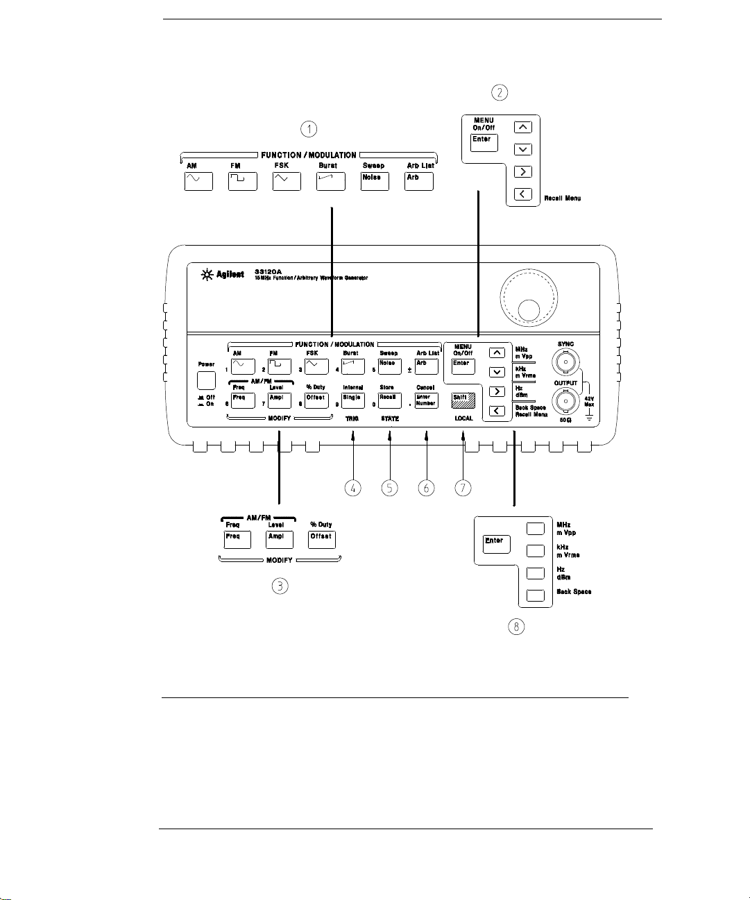
The Front Panel at a Glance
1 Function / Modulation keys
2 Menu operation keys
3 Waveform mod ify keys
4 Single / Internal Trigger key
(Burst and Sweep only)
2
5 Recall / Store instrument state key
6 Enter Number key
7 Shift / Local key
8 Enter Number “units” keys
Page 5
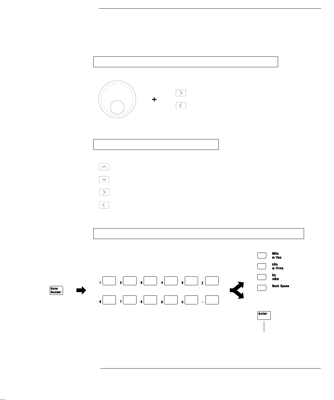
Front-Panel Number Entry
You can enter numbers from the front-panel using one of three methods.
Use the knob and the arrow keys to modify the displayed number.
Use the arrow keys to edit individual digits.
Increments the flashing digit.
Decrements the flashing digit.
Moves the flashing digit
Moves the flashing digit
to the right.
to the left.
Use the “Enter Number” mode to enter a number with the appropriate units.
Use “Enter” for those operations that do not
require units to be specified (AM Level,
Offset, % Duty, and Store/Recall State).
3
Page 6
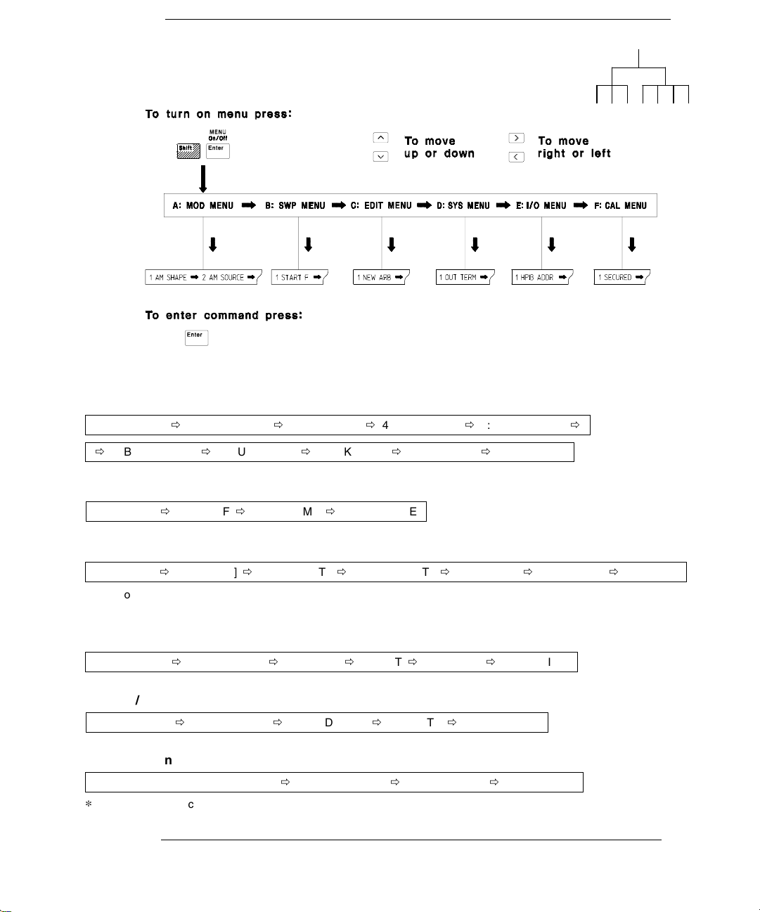
The Front-Panel Menu at a Glance
The menu is organized in a top-down tree structure with three levels.
A: MODulation MENU
1: AM SHAPE Õ 2: AM SOURCE Õ 3: FM SHAPE Õ 4: BURST CNT Õ 5: BURST RATE Õ
Õ 6: BURST PHAS Õ 7: BURST SRC Õ 8: FSK FREQ Õ 9: FSK RATE Õ 10: FSK SRC
B: SWP (Sweep) MENU
1: START F Õ 2: STOP F Õ 3: SWP TIME Õ 4: SWP MODE
C: EDIT MENU
1: NEW ARB Õ [ 2: POINTS ] Õ [ 3: LINE EDIT ] Õ [ 4: POINT EDIT ] Õ [ 5: INVERT ] Õ [ 6: SAVE AS ] Õ 7: DELETE
The commands enclosed in square brackets ( [ ] ) are “hidden” until you make a selection from the
*
NEW ARB command to initiate a new edit session.
*
D: SYStem MENU
1: OUT TERM Õ 2: POWER ON Õ 3: ERROR Õ 4: TEST Õ 5: COMMA Õ 6: REVISION
E: Input / Output MENU
1: HPIB ADDR Õ 2: INTERFACE Õ 3: BAUD RATE Õ 4: PARITY Õ 5: LANGUAGE
F: CALibration MENU
1: SECURED or [ 1: UNSECURED ] Õ [ 2: CALIBRATE ] Õ 3: CAL COUNT Õ 4: MESSAGE
The commands enclosed in square brackets ( [ ] ) are “hidden” unless the function generator
*
is UNSECURED for calibration.
*
4
Page 7
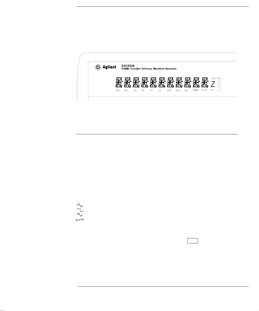
Display Annunciators
Adrs
Rmt
Trig
AM
FM
Ext
FSK
Burst
Swp
ERROR
Offset
Shift
Num
Arb
Function generator is addressed to listen or talk over a remote interface.
Function generator is in remote mode (remote interface).
Function generator is waiting for a single trigger or external trigger (Burst, Sweep).
AM modulation is enabled.
FM modulation is enabled.
Function generator is set for an external modulation source (AM, FSK, Burst).
FSK (frequency-shift keying) modulation is enabled.
Burst modulation is enabled.
Sweep mode is enabled.
Hardware or remote interface command errors are detected.
The waveform is being output with an offset voltage.
“Shift” key has been pressed. Press “Shift” again to turn off.
“Enter Number” mode is enabled. Press “Shift-Cancel” to disable.
Arbitrary waveform function is enabled.
Sine waveform function is enabled.
Square waveform function is enabled.
Triangle waveform function is enabled.
Ramp waveform function is enabled.
To review the display annunciators, hold down the Shift key as you
turn on the function generator.
5
Page 8
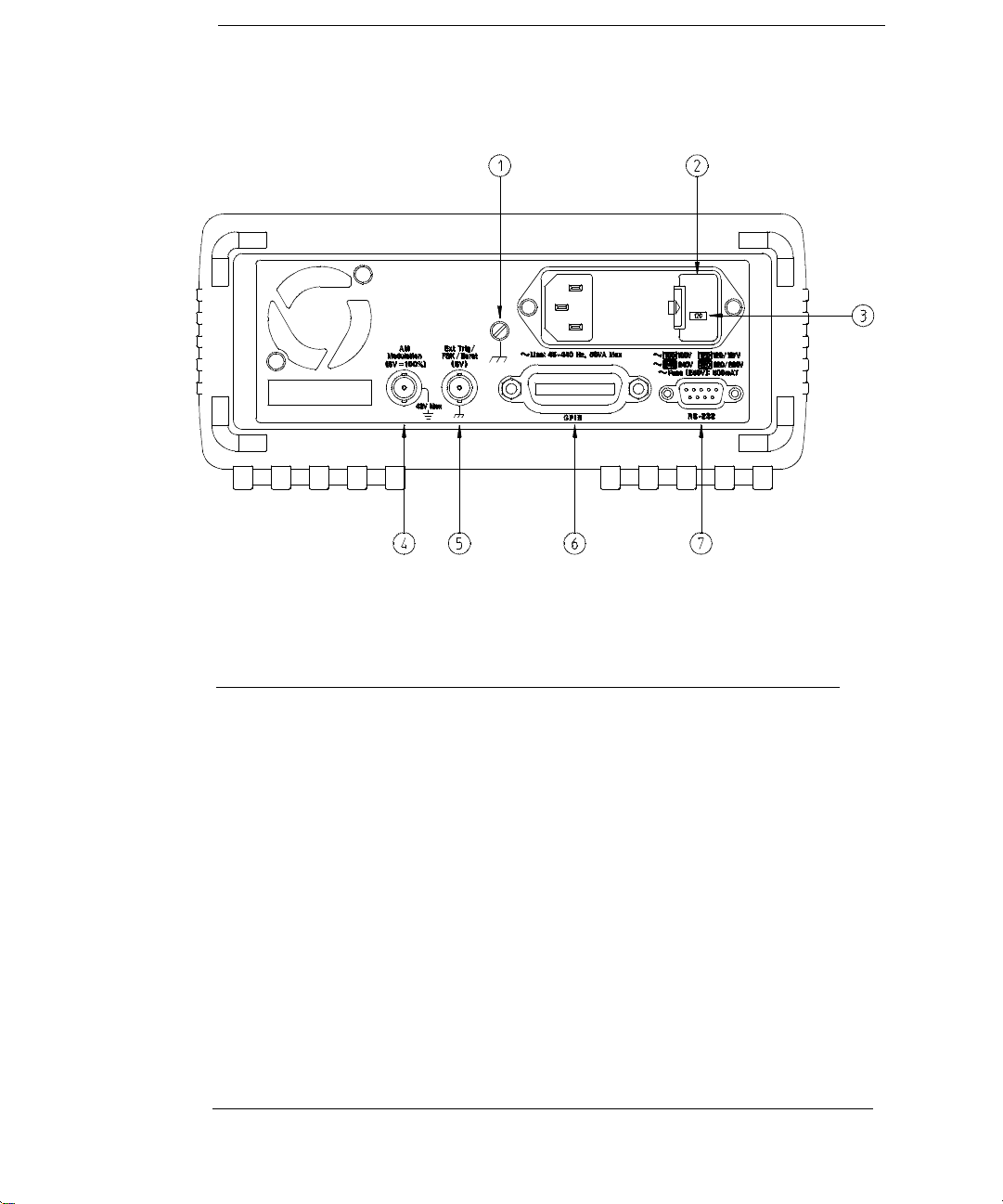
The Rear Panel at a Glance
1 Chassis ground
2 Power-line fuse-holder assembly
3 Power-line voltage setting
4 AM modulation input terminal
Use the front-panel Input / Output Menu to:
5 External Trigger / FSK / Burst modulation
input terminal
6 GPIB (IEEE-488) interface connector
7 RS-232 interface connector
Select the GPIB or RS-232 interface (see chapter 4 in User’s Guide).
Set the GPIB bus address (see chapter 4 in User’s Guide).
Set the RS-232 baud rate and parity (see chapter 4 in User’s Guide).
6
Page 9

In This Book
Specifications Chapter 1 lists the function generator’s specifications
and describes how to interpret these specifications.
Quick Start Chapter 2 prepares the function generator for use and
helps you get familiar with a few of its front-panel features.
Front-Panel Menu Operation Chapter 3 introduces you to the front-panel
menu and describes some of the function generator’s menu features.
Calibration Procedures Chapter 4 provides calibration, verification,
and adjustment procedures for the function generator.
Theory of Operation Chapter 5 describes block and circuit level theory
related to the operation the function generator.
Service Chapter 6 provides guidelines for returning your function
generator to Agilent for servicing, or for servicing it yourself.
Replaceable Parts Chapter 7 contains a detailed parts lists of the
function generator.
Schematics Chapter 8 contains the function generator’s block diagram,
schematics, disassembly drawings, and component locator drawings.
For information on using the Phase-Lock Option for the 33120A, refer to
the User’s and Service Guide included with the Option 001.
If you have questions relating to the operation of the 33120A,
call 1-800-452-4844 in the United States, or contact your nearest
Agilent Technologies Sales Office.
If you believe your 33120A has failed, refer to “Operating Checklist”,
“Types of Service Available”, and “Repackaging for Shipment” at the
beginning of chapter 6.
7
Page 10

8
Page 11

Contents
Chapter 1 Specifications
Chapter 2 Quick Start
To prepare the function generator for use 21
If the function generator does not turn on 22
To adjust the carrying handle 24
To set the output frequency 25
To set the output amplitude 26
To set a dc offset voltage 27
To set the duty cycle 28
To output a stored arbitrary waveform 29
To output a dc voltage 30
To store the instrument state 31
To rack mount the function generator 33
Chapter 3 Front-Panel Menu Operation
Front-panel menu reference 37
A front-panel menu tutorial 39
To select the output termination 44
To output a modulated waveform 45
To unsecure the function generator for calibration 47
Contents
Chapter 4 Calibration Procedures
Agilent Calibration Services 51
Calibration Interval 51
Time Required for Calibration 51
Automating Calibration Procedures 52
Recommended Test Equipment 52
Test Considerations 53
Performance Verification Tests 54
Frequency Verification 56
Function Gain and Linearity Verification 56
DC Function Offset Verification 57
AC Amplitude Verification 57
Amplitude Flatness Verification 60
AM Modulation Depth Verification 61
Optional Performance Verification Tests 62
9
Page 12

Contents
Contents
Chapter 4 Calibration Procedures (continued)
Calibration Security Code 64
Calibration Count 66
Calibration Message 66
General Calibration/Adjustment Procedure 67
Aborting a Calibration in Progress 69
Frequency and Burst Rate Adjustment 69
Function Gain and Linearity Adjustment 70
AC Amplitude Adjustment (High-Z) 70
Modulation Adjustment 72
AC Amplitude Adjustment (50
DC Output Adjustment 76
Duty Cycle Adjustment 77
AC Amplitude Flatness Adjustment 77
Output Amplifier Adjustment (Optional) 80
Error Messages 81
Chapter 5 Theory of Operation
Block Diagram Overview 85
Output Attenuator 86
Output Amplifier 87
AM Modulation 89
Pre-attenuator 90
Square Wave and Sync 90
Filters 92
Waveform DAC/Amplitude Leveling/Waveform RAM 93
Direct Digital Synthesis (DDS ASIC) 95
System DACs 96
Floating Logic 97
Earth-Referenced Logic 98
Power Supplies 98
Display and Keyboard 100
W) 73
10
Page 13

Contents
Chapter 6 Service
Operating Checklist 103
Types of Service Available 104
Repackaging for Shipment 105
Cleaning 105
Electrostatic Discharge (ESD) Precautions 106
Surface Mount Repair 106
To Replace the Power-Line Fuse 107
To Replace the Output Protection Fuse (F801) 107
Troubleshooting Hints 108
Self-Test Procedures 110
Chapter 7 Replaceable Parts
Replaceable Parts 113
Chapter 8 Schematics
33120A Block Diagram 129
Mechanical Disassembly 130
Floating Logic Schematic 131
Digital Waveform Data Synthesis 132
System DAC Schematic 133
Waveform DAC Schematic 134
Filters Schematic 135
Sync, Square Wave, and Attenuator Schematic 136
Output Amplifier Schematic 137
Output Attenuator Schematic 138
Earth Reference Logic Schematic 139
Power Supplies Schematic 140
Display and Keyboard Schematic 141
33120-66521 Component Locator Diagram 142
33120-66502 Component Locator Diagram 143
Contents
11
Page 14

Contents
12
Page 15

1
1
Specifications
Page 16
Chapter 1 Specifications
Agilent 33120A Function Generator
WAVEFORMS
Standard Waveforms:
Sine, Square, Triangle,
Ramp, Noise, DC volts,
Sine(x)/x, Negative Ramp,
Exponential Rise,
Exponential Fall, Cardiac
Arbitrary Waveforms:
Waveform Length:
Amplitude Resolution:
Sample Rate:
Non-Volatile Memory:
8 to 16,000 points
12 bits (including sign)
40 MSa / sec
Four 16,000-point waveforms
FREQUENCY CHARACTERISTICS
Sine:
Square:
Triangle:
Ramp:
Noise (Gaussian):
Arbitrary Waveforms:
8 to 8,192 points:
8,193 to 12,287 points:
12,288 to 16,000 points:
Resolution:
Accuracy:
Temperature Coefficient:
Aging:
m
Hz – 15 MHz
100
m
Hz – 15 MHz
100
m
Hz – 100 kHz
100
m
Hz – 100 kHz
100
10 MHz bandwidth
m
Hz – 5 MHz
100
m
Hz – 2.5 MHz
100
m
Hz – 200 kHz
100
10
m
Hz or 10 digits
10 ppm in 90 days,
20 ppm in 1 year,
C – 28C
18
< 2 ppm /
C
< 10 ppm / yr
SINEWAVE SPECTRAL PURITY (into 50
SIGNAL CHARACTERISTICS
Squarewave
Rise/Fall Time:
Overshoot:
Asymmetry:
Duty Cycle:
Triangle, Ramp, Arb
Rise/Fall Time:
Linearity:
Settling Time:
Jitter:
OUTPUT CHARACTERISTICS
(4)
W
(3)
W
):
Amplitude (into 50
Accuracy (at 1 kHz):
Flatness
< 100 kHz:
100 kHz to 1 MHz:
1 MHz to 15 MHz:
1 MHz to 15 MHz:
Offset (into 50
Accuracy:
Output Impedance:
Resolution:
Output Units:
Isolation:
W
)
Protection:
< 20 ns
< 4%
1% + 5 ns
20% to 80% (to 5 MHz)
40% to 60% (to 15 MHz)
40 ns (typical)
< 0.1% of peak output
< 250 ns to 0.5% of final value
< 25 ns
(2)
50 mVpp – 10 Vpp
):
1% of specified output
(sine wave relative to 1 kHz)
1% (0.1 dB)
1.5% (0.15 dB)
2% (0.2 dB) Ampl 3Vrms
3.5% (0.3 dB) Ampl < 3Vrms
5 Vpk ac + dc
2% of setting + 2 mV
50 ohms fixed
3 digits, Amplitude and Offset
Vpp, Vrms, dBm
42 Vpk maximum to earth
Short-circuit protected
15 Vpk overdrive < 1 minute
(1)
Harmonic Distortion
DC to 20 kHz:
20 kHz to 100 kHz:
100 kHz to 1 MHz:
1 MHz to 15 MHz:
Total Harmonic Distortion
DC to 20 kHz:
Spurious (non-harmonic)
Output (DC to 1 MHz):
Output (> 1 MHz):
Phase Noise:
-70 dBc
-60 dBc
-45 dBc
-35 dBc
< 0.04%
< -65 dBc
< -65 dBc + 6 dB/octave
< -55 dBc in a 30 kHz band
14
(1) Add 1/10th of output amplitude and offset specification
C for operation outside of 18C to 28C range
per
(1-year specification).
(2) 100 mVpp – 20 Vpp amplitude into open-circuit load.
(3) Offset
2 X peak-to-peak amplitude.
(4) For square wave outputs, add 2% of output amplitude
additional error.
Page 17
Chapter 1 Specifications
Agilent 33120A Function Generator
1
MODULATION CHARACTERISTICS
AM Modulation
Carrier -3 dB Freq:
Modulation:
Frequency:
Depth:
Source:
FM Modulation
Modulation:
Frequency:
Peak Deviation:
Source:
Burst Modulation
Carrier Frequency:
Count:
Start Phase:
Internal Rate:
Gate Source:
Trigger Source:
FSK Modulation
Frequency Range:
Internal Rate:
Source:
10 MHz (typical)
Any internal waveform plus Arb
10 mHz to 20 kHz (
2.5 kHz, then decreases linearly
0.4% at upper limit)
to
0% to 120%
Internal / External
Any internal waveform plus Arb
10 mHz to 10 kHz (
600 Hz, then decreases linearly
0.8% at upper limit)
to
10 mHz to 15 MHz
Internal Only
5 MHz max.
1 to 50,000 cycles, or Infinite
to +360
-360
10 mHz to 50 kHz 1%
Internal or External Gate
Single, External, or Internal Rate
10 mHz to 15 MHz (
600 Hz, then decreases linearly
4% at upper limit)
to
10 mHz to 50 kHz
Internal / External (1 MHz max.)
0.05% to
0.05% to
0.05% to
(1)
SYSTEM CHARACTERISTICS
Configuration Times
Function Change:
Frequency Change:
Amplitude Change:
Offset Change:
Select User Arb:
Modulation Parameter Change:
Arb Download Times over GPIB:
Arb Length Binary ASCII Integer ASCII Real
16,000 points 8 sec 81 sec 100 sec
8,192 points 4 sec 42 sec 51 sec
4,096 points 2.5 sec 21 sec 26 sec
2,048 points 1.5 sec 11 sec 13 sec
Arb Download Times over RS-232 at 9600 Baud:
Arb Length Binary ASCII Integer ASCII Real
16,000 points 35 sec 101 sec 134 sec
8,192 points 18 sec 52 sec 69 sec
4,096 points 10 sec 27 sec 35 sec
2,048 points 6 sec 14 sec 18 sec
(3)
(2)
(3)
80 ms
30 ms
30 ms
10 ms
100 ms
< 350 ms
(4)
(5)
(6)
FREQUENCY SWEEP
Type:
Direction:
Start F / Stop F:
Time:
Source:
Linear or Logarithmic
Up or Down
10 mHz to 15 MHz
1 ms to 500 sec
Single, External, or Internal
REAR-PANEL INPUTS
External AM
Modulation:
External Trigger/FSK
Burst Gate:
Latency:
Jitter:
(1)
5 Vpk = 100% Modulation
W
Input Resistance
5 k
TTL (low true)
m
s
1.3
25 ns
0.1%
(1) Trigger source ignored when External Gate is selected.
(2) Time to change parameter and output the new signal.
(3) Modulation or sweep off.
(4) Times for 5-digit and 12-digit numbers.
(5) For 4800 baud, multiply the download times by two;
For 2400 baud, multiply the download times by four, etc.
(6) Time for 5-digit numbers. For 12-digit numbers,
multiply the 5-digit numbers by two.
15
Page 18

Chapter 1 Specifications
Agilent 33120A Function Generator
GENERAL SPECIFICATIONS
Power Supply:
(1)
Power-Line Frequency:
Power Installation:
Power Consumption:
Operating Environment:
Storage Environment:
State Storage Memory:
Dimensions (W x H x D)
Bench Top:
Rack Mount:
Weight:
100V / 120V / 220V / 240V
10%
(switch selectable)
50 Hz to 60 Hz
400 Hz
10% and
10%. Automatically
sensed at power-on.
CAT II
50 VA peak (28 W average)
0
C to 55C
80% Relative Humidity to 40
C
Indoor or sheltered location
-40
C to 70C
Power-off state automatically
saved. Three (3) UserConfigurable Stored States,
Arbitrary waveforms stored
separately.
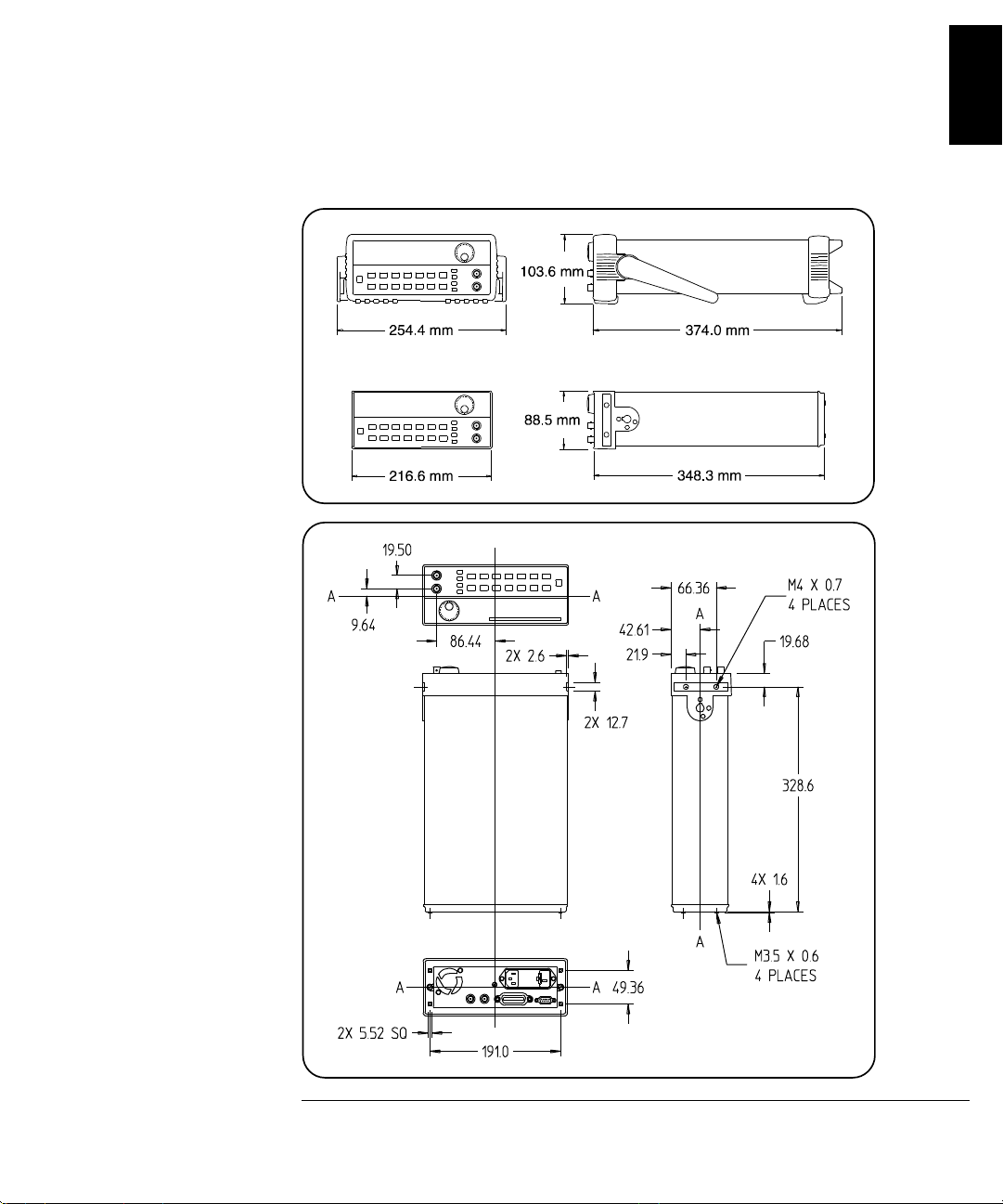
254.4 mm x 103.6 mm x 374 mm
212.6 mm x 88.5 mm x 348.3 mm
4 kg (8.8 lbs)
Safety Designed to:
EMC:
Vibration and Shock:
Acoustic Noise:
Warm-Up Time:
Warranty:
Remote Interface:
Programming Language:
Accessories Included:
N10149
EN61010, CSA1010, UL-1244
EN61326, 1:1997 + 1A:1998
MIL-T-28800E, Type III, Class 5
(data on file)
30 dBa
1 hour
3 years standard
IEEE-488 and RS-232 standard
SCPI-1993, IEEE-488.2
User’s Guide, Service Guide,
Quick Reference Card,
IntuiLink Arb software,
RS-232 cable, Test Report,
and power cord.
(1) For 400 Hz operation at 120 Vac, use the 100 Vac
line-voltage setting.
16
Page 19
Chapter 1 Specifications
Agilent 33120A Function Generator
PRODUCT DIMENSIONS
1
TOP
All dimensions are
shown in millimeters.
17
Page 20

18
Page 21

2
2
Quick Start
Page 22

Quick Start
One of the first things you will want to do with your function generator is
to become acquainted with its front panel. We have written the exercises
in this chapter to prepare the function generator for use and help you get
familiar with some of the front-panel operations.
The front panel has two rows of keys to select various functions and
operations. Most keys have a shifted function printed in blue above the
key. To perform a shifted function, press
turn on). Then, press the key that has the desired label above it. For
example, to select the
Shift AM (the shifted version of the key).
AM (amplitude modulation) function, press
Shift (the Shift annunciator will
If you accidentally press
Shift , just press it again to turn off the Shift
annunciator.
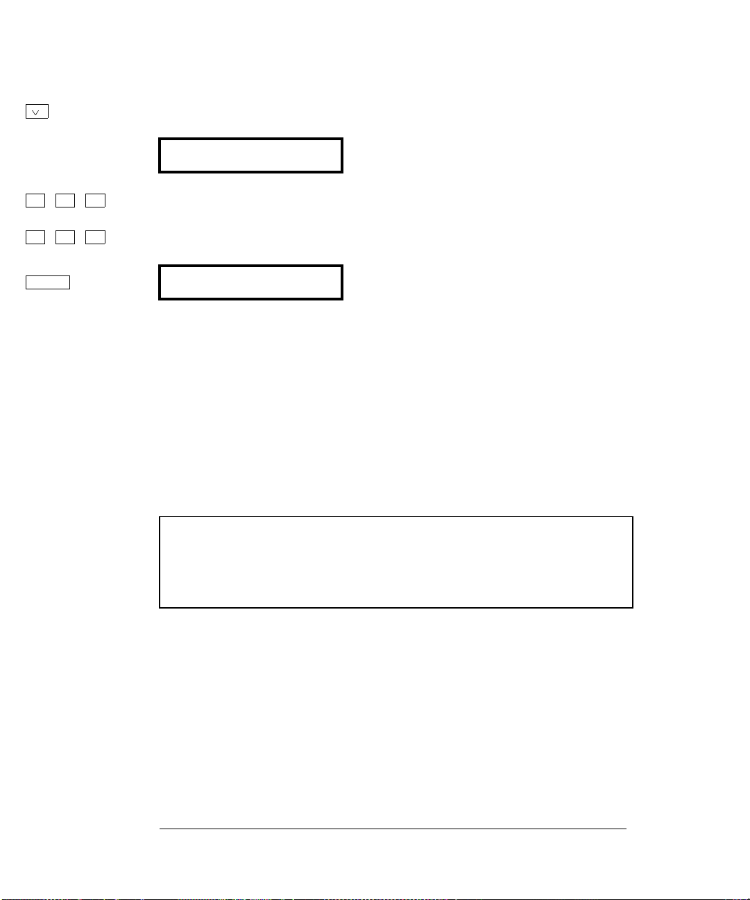
Most keys also have a number printed in green next to the key. To enable
the number mode, press
Enter Number (the Num annunciator will turn on).
Then, press the keys that have the desired numbers printed next to them.
For example, to select the number “10”, press
(next to the
If you accidentally press
off the
and Recall keys).
Enter Number , just press Shift Cancel to turn
Num annunciator.
Enter Number 1 0
20
Page 23

Chapter 2 Quick Start
To prepare the function generator for use
To prepare the function generator for use
The following steps help you verify that the function generator is
ready for use.
1 Check the list of supplied items.
Verify that you have received the following items with your function
generator. If anything is missing, contact your nearest Agilent
Technologies Sales Office.
One power cord.
One RS-232 serial cable.
One User’s Guide.
This Service Guide.
á
One folded Quick Reference card.
Certificate of Calibration.
Agilent IntuiLink Arb Waveform Generation Software.
2
2 Connect the power cord and turn on the function generator.
If the function generator does not turn on, see chapter 6 for troubleshooting
information. The front-panel display will light up while the function
generator performs its power-on self-test. The
displayed. Notice that the function generator powers up in the sine wave
function at 1 kHz with an amplitude of 100 mV peak-to-peak (into a 50
termination).
To review the power-on display with all annunciators turned on,
hold down
3Perform a complete self test.
The complete self-test performs a more extensive series of tests than
those performed at power-on. Hold down
switch to turn on the function generator; hold down the key for more than
5 seconds. The self-test will begin when you release the key.
If the self-test is successful, “
If the self-test is not successful, “
annunciator turns on. See chapter 6 for instructions on returning the
function generator to Agilent for service.
Shift as you turn on the function generator.
PASS” is displayed on the front panel.
FAIL” is displayed and the ERROR
GPIB bus address is
Shift as you press the Power
W
21
Page 24

Chapter 2 Quick Start
If the function generator does not turn on
If the function generator does not turn on
Use the following steps to help solve problems you might experience
when turning on the function generator. If you need more help,
see chapter 6 for instructions on returning the function generator to
Agilent for service.
1 Verify that there is ac power to the function generator.
First, verify that the function generator’s Power switch is in the
“On” position. Also, make sure that the power cord is firmly plugged into
to the power module on the rear panel. You should also make sure that
the power source you plugged the function generator into is energized.
2 Verify the power-line voltage setting.
The line voltage is set to the proper value for your country when the
function generator is shipped from the factory. Change the voltage
setting if it is not correct. The settings are: 100, 120, 220, or 240 Vac
(for 230 Vac operation, use the 220 Vac setting).
See the next page if you need to change the line-voltage setting.
3 Verify that the power-line fuse is good.
The function generator is shipped from the factory with a 500 mAT fuse
installed. This is the correct fuse for all line voltages.
See the next page if you need to change the power-line fuse.
To replace the 500 mAT fuse, order Agilent part number 2110-0458.
22
Page 25
Chapter 2 Quick Start
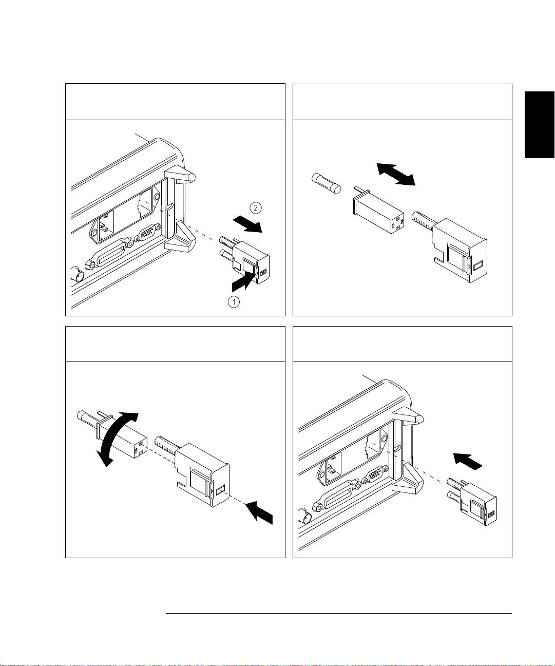
If the function generator does not turn on
1 Remove the power cord. Remove the
fuse-holder assembly from the rear panel.
3 Rotate the line-voltage selector until the
correct voltage appears in the window.
2 Remove the line-voltage selector from
the assembly.
Fuse: 500 mAT (for all line voltages)
Part Number: 2110-0458
4 Replace the fuse-holder assembly in
the rear panel.
2
100, 120, 220 (230), or 240 Vac
Verify that the correct line voltage is selected and the power-line fuse is good.
23
Page 26
Chapter 2 Quick Start
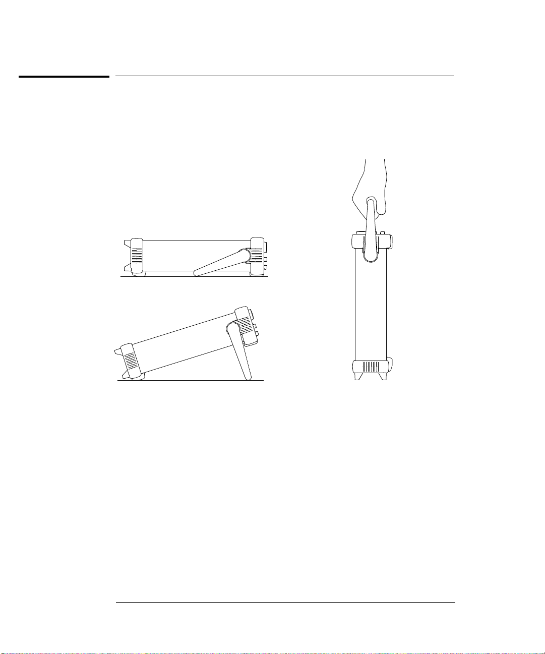
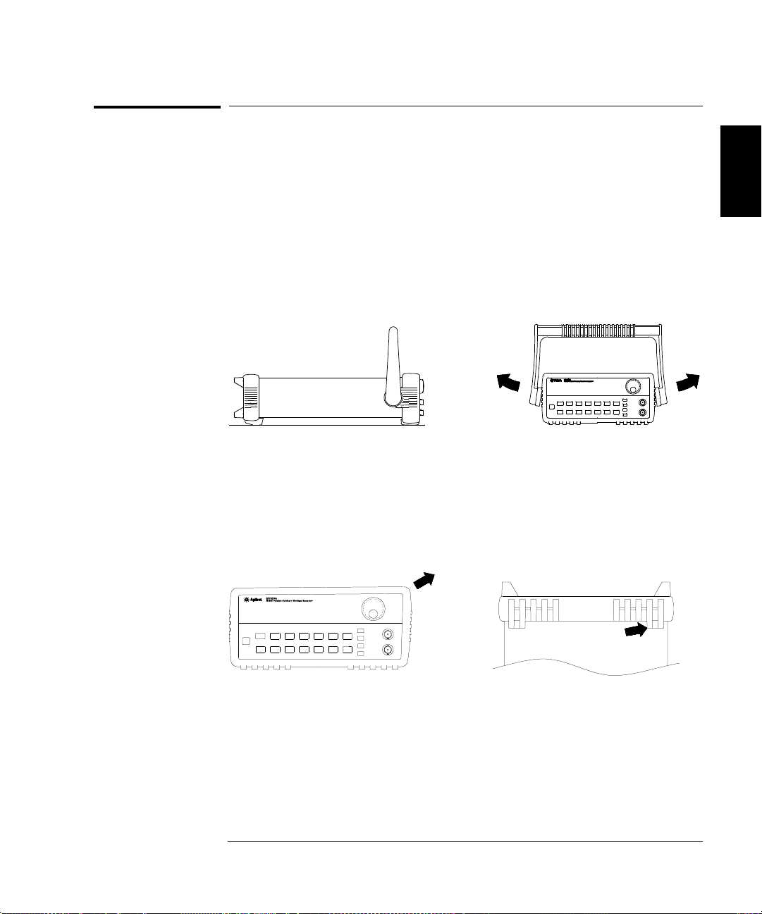
To adjust the carrying handle
To adjust the carrying handle
To adjust the position, grasp the handle by the sides and pull outward.
Then, rotate the handle to the desired position.
Bench-top viewing positions Carrying position
24
Page 27

Chapter 2 Quick Start
To set the output frequency
To set the output frequency
At power-on, the function generator outputs a sine wave at 1 kHz with
an amplitude of 100 mV peak-to-peak (into a 50
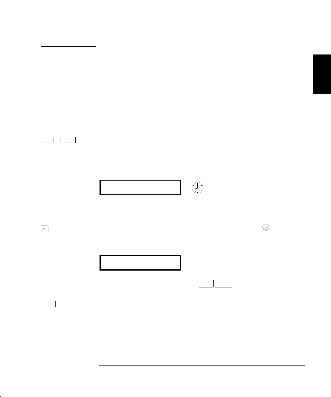
The following steps show you how to change the frequency to 1.2 MHz.
Freq 1 Enable the frequency modify mode.
The displayed frequency is either the power-on value or the previous
frequency selected. When you change functions, the same frequency is
used if the present value is valid for the new function.
1.000,000,0 KHz
W termination).
2
Enter Number 2 Enter the magnitude of the desired frequency.
1 2 . Notice that the Num annunciator turns on and “ENTER NUM” flashes on
1
the display, indicating that the number mode is enabled.
1.2
¾
MHz
m Vpp
To cancel the number mode, press
3 Set the units to the desired value.
Shift Cancel .
The units are selected using the arrow keys on the right side of the front
panel. As soon as you select the units, the function generator outputs the
waveform with the displayed frequency. To turn off the flashing digit,
move the cursor to the left of the display using the arrow keys.
1.200,000,0 MHz
1
You can also use the knob and arrow keys to enter a number.
25
Page 28

Chapter 2 Quick Start
To set the output amplitude
To set the output amplitude
At power-on, the function generator outputs a sine wave with an
amplitude of 100 mV peak-to-peak (into a 50
The following steps show you how to change the amplitude to 50 mVrms.
Ampl 1 Enable the amplitude modify mode.
The displayed amplitude is either the power-on value or the previous
amplitude selected. When you change functions, the same amplitude is
used if the present value is valid for the new function.
100.0 mVPP
W termination).
Enter Number 2 Enter the magnitude of the desired amplitude.
5 0 Notice that the Num annunciator turns on and “ENTER NUM” flashes on
1
the display, indicating that the number mode is enabled.
50
To cancel the number mode, press
Shift 3 Set the units to the desired value.
¿
kHz
m Vrms
The units are selected using the arrow keys on the right side of the front
panel. As soon as you select the units, the function generator outputs the
Shift Cancel .
waveform with the displayed amplitude. To turn off the flashing digit,
move the cursor to the left of the display using the arrow keys.
50.00 mVRMS
1
You can also use the knob and arrow keys to enter a number.
26
Page 29

Chapter 2 Quick Start
To set a dc offset voltage
To set a dc offset voltage
At power-on, the function generator outputs a sine wave with a dc offset
voltage of 0 volts (into a 50
how to change the offset to –1.5 mVdc.
Offset 1 Enable the offset modify mode.
The displayed offset voltage is either the power-on value or the previous
offset selected. When you change functions, the same offset is used if the
present value is valid for the new function.
+0.000 VDC
W termination). The following steps show you
2
Enter Number 2 Enter the magnitude of the desired offset.
1 . 5 Notice that the Num annunciator turns on and “ENTER NUM” flashes on
1
the display, indicating that the number mode is enabled. Notice that
toggles the displayed value between + and – .
-1.5
To cancel the number mode, press
Shift 3 Set the units to the desired value.
¿
kHz
m Vrms
At this point, the function generator outputs the waveform with the
displayed offset. Notice that the
Shift Cancel .
Offset annunciator turns on, indicating
that the waveform is being output with an offset. The annunciator will
turn on when the offset is any value other than 0 volts. To turn off the
flashing digit, move the cursor to the left of the display using the arrow keys.
-01.50 mVDC
1
You can also use the knob and arrow keys to enter a number.
27
Page 30

Chapter 2 Quick Start
To set the duty cycle
To set the duty cycle
Applies only to square waves. At power-on, the duty cycle for square waves
is 50%. You can adjust the duty cycle for a square waveform from 20%
to 80%, in increments of 1% (for frequencies above 5 MHz, the range is 40%
to 60%). The following steps show you how to change the duty cycle to 45%.
1 Select the square wave function.
Notice that the annunciator turns on, indicating that the square
wave function is enabled.
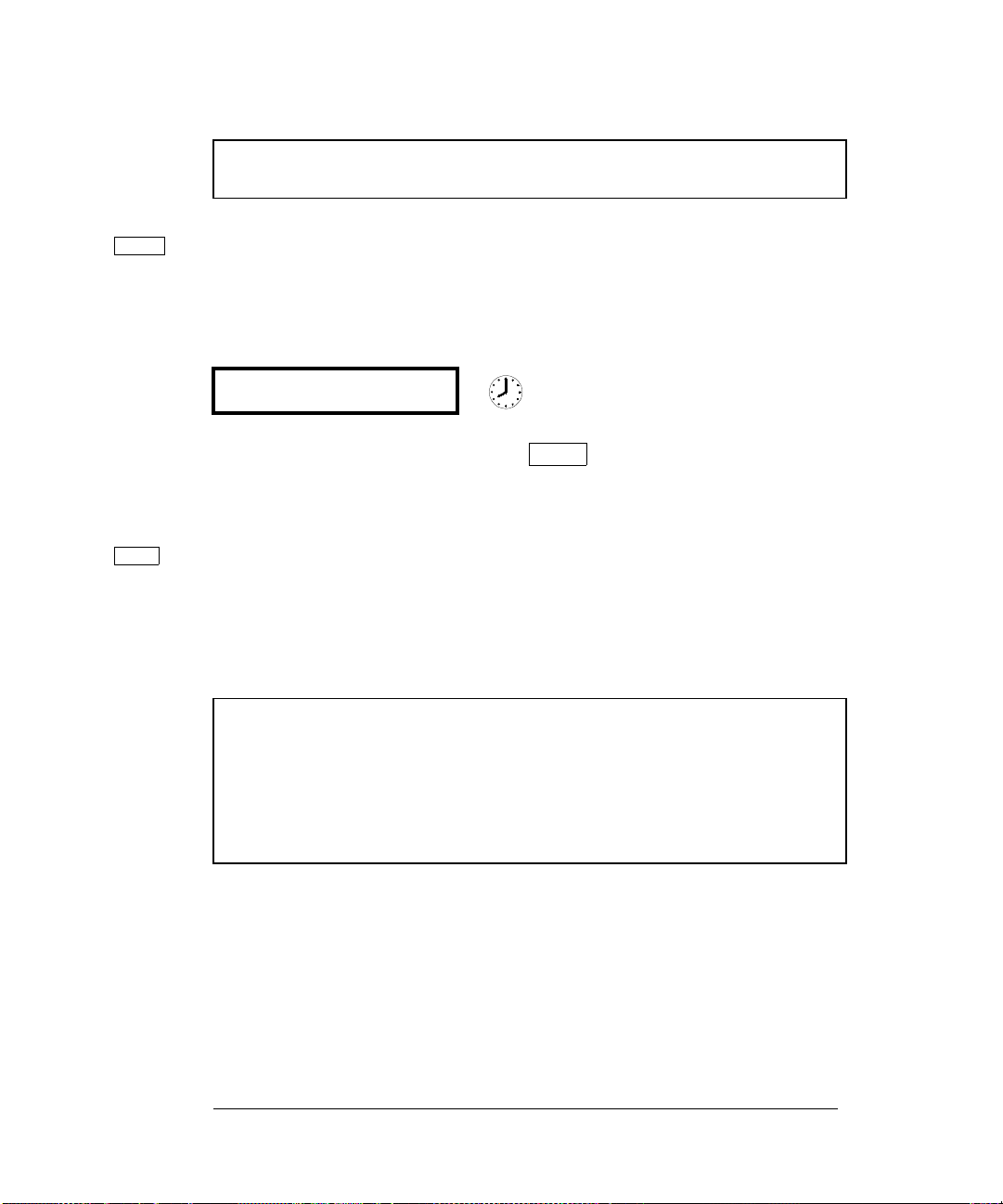
Shift % Duty 2 Enable the duty cycle modify mode.
The displayed duty cycle is either the power-on value or the previous
value selected.
50 % DUTY
This message appears on the display for approximately 10 seconds.
Repeat this step as needed.
Enter Number
4 5 Notice that the Num annunciator turns on and “ENTER NUM” flashes on
3 Enter the desired duty cycle.
1
the display, indicating that the number mode is enabled.
45
To cancel the number mode, press
Enter 4 Output the waveform with the displayed duty cycle.
Shift Cancel .
45 % DUTY
1
You can also use the knob and arrow keys to enter a number.
28
Page 31

Chapter 2 Quick Start
To output a stored arbitrary waveform
To output a stored arbitrary waveform
There are five built-in arbitrary waveforms stored in non-volatile memory
for your use. You can output these waveforms directly from non-volatile
memory. The following steps show you how to output an “exponential rise”
waveform from memory.
Shift Arb List 1 Display the list of arbitrary waveforms.
The list contains the five built-in arbitrary waveforms (sinc, negative
ramp, exponential rise, exponential fall, and cardiac). The list may also
contain up to four user-defined arbitrary waveform names. The first
choice on this level is “
SINC
This message appears on the display for approximately 10 seconds.
Repeat this step as needed.
> 2 Move across to the EXP_RISE choice.
>
SINC”.
2
1
EXP_RISE
Enter 3 Select and output the displayed arbitrary waveform.
Notice that the
Arb annunciator turns on, indicating that the output is an
arbitrary waveform. The waveform is output using the present settings
for frequency, amplitude, and offset unless you change them.
The selected waveform is now assigned to the
Arb key. Whenever you
press this key, the selected arbitrary waveform is output.
1
You can also use the knob to scroll left or right through the choices in the list.
29
Page 32

Chapter 2 Quick Start
To output a dc voltage
To output a dc voltage
In addition to generating waveforms, you can also output a dc voltage in
the range
how to output +155 mVdc.
5 Vdc (into a 50W termination). The following steps show you
1 Press the key and hold it down for more than 2 seconds.
To enter the dc voltage mode, press the
of function keys and
Offset
Offset key or any key in the top row
hold it down for more than 2 seconds. The displayed
voltage is either the power-on value or the previous offset voltage selected.
DCV
+0.000 VDC
Enter Number
1 5 5 Notice that the Num annunciator turns on and “ENTER NUM” flashes on
2 Enter the magnitude of the desired voltage.
1
the display, indicating that the number mode is enabled.
155
To cancel the number mode, press
Shift 3 Set the units to the desired value.
Shift Cancel .
¿
kHz
m Vrms
At this point, the function generator outputs the displayed dc voltage.
Notice that the
Offset annunciator turns on (all other annunciators are
off), indicating that a dc voltage is being output. The annunciator will
turn on when the offset is any value other than 0 volts.
+155.0 mVDC
1
You can also use the knob and arrow keys to enter a number.
30
Page 33
Chapter 2 Quick Start
To store the instrument state
To store the instrument state
You can store up to three different instrument states in non-volatile
memory. This enables you to recall the entire instrument configuration
with just a few key presses from the front panel. The following steps show
you how to store and recall a state.
1 Set up the function generator to the desired configuration.
The state storage feature “remembers” the function, frequency,
amplitude, dc offset, duty cycle, as well as any modulation parameters.
Shift Store 2 Turn on the state storage mode.
Three memory locations (numbered 1, 2, and 3) are available to store
instrument configurations. The instrument configuration is stored in
non-volatile memory and is remembered when power has been off.
STORE 1
2
This message appears on the display for approximately 10 seconds.
Repeat this step as needed.
¾
3 Store the instrument state in memory location “2”.
Use the up and down arrow keys to select the memory location.
STORE 2
To cancel the store operation, press
time-out after 10 seconds.
Enter 4 Save the instrument state.
The instrument state is now stored. To recall the stored state, turn to the
next page.
1
You can also use the knob or “enter number” mode to enter a memory location.
1
Shift Store again or let the display
31
Page 34
Chapter 2 Quick Start
To store the instrument state
To verify that the state was stored properly, you can turn the power off
before recalling the state.
Recall 5 Recall the stored instrument state.
To recall the stored state, you must use the same memory location used
previously to store the state. Use the up and down arrow keys to change
the displayed storage location.
RECALL 2
To cancel the restore operation, press
This message appears on the display for approximately 10 seconds.
Repeat this step as needed.
Enter 6 Restore the instrument state.
The function generator should now be configured in the same state as
when you stored the setup on the previous page.
When power is turned off, the function generator automatically stores
its state in memory location “0”. You can recall the power-down state,
but you cannot store the state to location “0” from the front panel.
Use the POWER ON ENABLE command in the SYS MENU to
automatically recall the power-down state when power is turned on.
See chapter 3 for more information on using the front-panel menus.
Recall again.
32
Page 35
Chapter 2 Quick Start
To rack mount the function generator
To rack mount the function generator
You can mount the function generator in a standard 19-inch rack
cabinet using one of three optional kits available. Instructions and
mounting hardware are included with each rack-mounting kit.
Any Agilent System II instrument of the same size can be rack-mounted
beside the 33120A Function Generator.
Remove the carrying handle, and the front and rear rubber bumpers,
before rack-mounting the function generator.
2
To remove the handle, rotate it to the vertical position and pull the ends outward.
Front Rear (bottom view)
To remove the rubber bumper, stretch a corner and then slide it off.
33
Page 36
Chapter 2 Quick Start
To rack mount the function generator
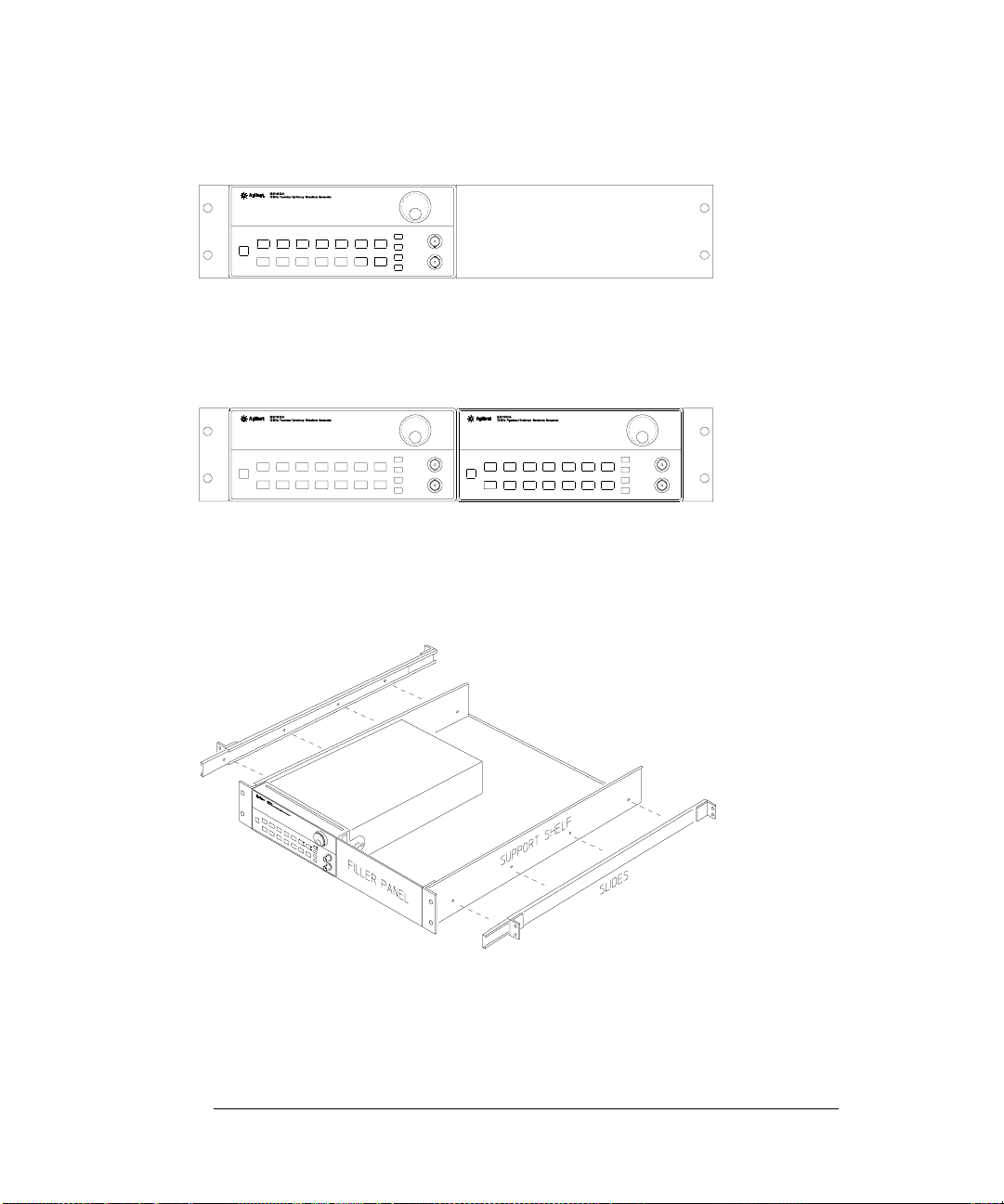
To rack mount a single instrument, order adapter kit 5063-9240.
To rack mount two instruments side-by-side, order lock-link kit 5061-9694
and flange kit 5063-9212.
To install one or two instruments in a sliding support shelf, order shelf 5063-9255,
and slide kit 1494-0015 (for a single instrument, also order filler panel 5002-3999).
34
Page 37

3
3
Front-Panel
Menu Operation
Page 38

Front-Panel Menu Operation
By now you should be familiar with some of the basic features of the front
panel. Chapter 2 shows you how to prepare the function generator for use
and describes a few of the front-panel features. If you are not familiar
with this information, we recommend that you read chapter 2, “Quick Start,”
starting on page 19.
Chapter 3 introduces you to the use of the front-panel menu. This chapter
does not give a detailed description of every front-panel key or menu
operation. It does, however, give you an overview of front-panel menu
operations related to verification, adjustment and service. See chapter 3
“Features and Functions” in the User’s Guide for a complete discussion of
the function generator’s capabilities and operation.
If you purchased the Phase-Lock Option for the 33120A, an additional
menu
(G: PHASE MENU) is available from the front panel. For inform-
ation on using the Phase-Lock Option, refer to the User’s and Service
Guide included with Option 001.
36
Page 39

Chapter 3 Front-Panel Menu Operation
Front-panel menu reference
Front-panel menu reference
A: MODulation MENU
1: AM SHAPE Õ 2: AM SOURCE Õ 3: FM SHAPE Õ 4: BURST CNT Õ 5: BURST RATE Õ
Õ 6: BURST PHAS Õ 7: BURST SRC Õ 8: FSK FREQ Õ 9: FSK RATE Õ 10: FSK SRC
1: AM SHAPE Selects the shape of the AM modulating waveform.
2: AM SOURCE Enables or disables the internal AM modulating source.
3: FM SHAPE Selects the shape of the FM modulating waveform.
4: BURST CNT Sets the number of cycles per burst (1 to 50,000 cycles).
5: BURST RATE Sets the burst rate in Hz for an internal burst source.
6: BURST PHAS Sets the starting phase angle of a burst (-360 to +360 degrees).
7: BURST SRQ Selects an internal or external gate source for burst modulation.
8: FSK FREQ Sets the FSK “hop” frequency.
9: FSK RATE Selects the internal FSK rate between the carrier and FSK frequency.
10: FSK SRC Selects an internal or external source for the FSK rate.
B: SWP (Sweep) MENU
3
1: START F Õ 2: STOP F Õ 3: SWP TIME Õ 4: SWP MODE
1: START F Sets the start frequency in Hz for sweeping.
2: STOP F Sets the stop frequency in Hz for sweeping.
3: SWP TIME Sets the repetition rate in seconds for sweeping.
4: SWP MODE Selects linear or logarithmic sweeping.
C: EDIT MENU *
1: NEW ARB Õ 2: POINTS Õ [3: LINE EDIT] Õ [4: POINT EDIT] Õ [5: INVERT] Õ [6: SAVE AS] Õ 7:DELETE
1: NEW ARB Initiates a new arb waveform or loads the selected arb waveform.
2: POINTS Sets the number of points in a new arb waveform (8 to 16,000 points).
3: LINE EDIT Performs a linear interpolation between two points in the arb waveform.
4: POINT EDIT Edits the individual points of the selected arb waveform.
5: INVERT Inverts the selected arb waveform by changing the sign of each point.
6: SAVE AS Saves the current arb waveform in non-volatile memory.
7: DELETE Deletes the selected arb waveform from non-volatile memory.
* The commands enclosed in square brackets ( [ ] ) are “hidden” until you make a selection from the NEW ARB
command to initiate a new edit session.
37
Page 40

Chapter 3 Front-Panel Menu Operation
Front-panel menu reference
D: SYStem MENU
1: OUT TERM Õ 2: POWER ON Õ 3: ERROR Õ 4: TEST Õ 5: COMMA Õ 6:REVISION
1: OUT TERM Selects the output termination (50
2: POWER ON Enables or disables automatic power-up in power-down state “0”.
3: ERROR Retrieves errors from the error queue (up to 20 errors).
4: TEST Performs a complete self-test.
5: COMMA Enables or disables a comma separator between digits on the display.
6: REVISION Displays the function generator’s firmware revision codes.
W
or high impedance).
E: Input / Output MENU
1: HPIB ADDR Õ 2: INTERFACE Õ 3: BAUD RATE Õ 4: PARITY Õ 5: LANGUAGE
1: HPIB ADDR Sets the GPIB bus address (0 to 30).
2: INTERFACE Selects the GPIB or RS-232 interface.
3: BAUD RATE Selects the baud rate for RS-232 operation.
4: PARITY Selects even, odd, or no parity for RS-232 operation.
5: LANGUAGE Verifies the interface language: SCPI.
F: CALibration MENU *
1: SECURED Õ [1: UNSECURED] Õ [2: CALIBRATE] Õ 3: CAL COUNT Õ 4: MESSAGE
1: SECURED The function generator is secured against calibration; enter code to unsecure.
1: UNSECURED The function generator is unsecured for calibration; enter code to secure.
2: CALIBRATE Performs individual calibrations; must be UNSECURED.
3: CAL COUNT Reads the total number of times the function generator has been calibrated.
4: MESSAGE Reads the calibration string (up to 11 characters) entered from remote.
* The commands enclosed in square brackets ( [ ] ) are “hidden” unless the function generator is UNSECURED for
calibration.
38
Page 41

Chapter 3 Front-Panel Menu Operation
A front-panel menu tutorial
A front-panel menu tutorial
This section is a step-by-step tutorial which shows you how to use the
front-panel menu. We recommend that you spend a few minutes with this
tutorial to get comfortable with the structure and operation of the menu
before attempting verification, calibration, or adjustments.
The menu is organized in a top-down tree structure with three levels
(menus, commands, and parameters). You move down
the menu tree to get from one level to the next. Each of the three levels
has several horizontal choices which you can view by moving left
or right
> .
Menus
Commands
¿
or up
¾
<
3
Parameters
The menu is organized in a top-down tree structure with three levels.
To turn on the menu, press Shift Menu On/Off .
To turn off the menu, press Shift Menu On/Off .
To execute a menu command, press Enter .
To recall the last menu command that was executed,
press
Shift Recall Menu .
To turn off the menu at any time without saving changes,
press
Shift Cancel .
39
Page 42

Chapter 3 Front-Panel Menu Operation
A front-panel menu tutorial
Messages Displayed During Menu Use
TOP OF MENU You pressed
¾ while on the “MENUS” level; this is the top
level of the menu and you cannot go any higher.
To turn off the menu, press
a level, press
MENUS
COMMANDS
< or > . To move down a level, press
You are on the “MENUS” level. Press < or > to view the choices.
You are on the “COMMANDS” level. Press < or > to view the
Shift Menu On/Off . To move across the choices on
¿ .
command choices within the selected menu group.
PARAMETER You are on the “
PARAMETER” level. Press < or > to view
and edit the parameter for the selected command.
MENU BOTTOM You pressed
¿ while on the “PARAMETER” level; this is the
bottom level of the menu and you cannot go any lower.
To turn off the menu, press
ENTERED The change made on the “
displayed after you press
MIN VALUE The value you specified on the “
Shift Menu On/Off . To move up a level, press
PARAMETER” level is saved. This is
Enter (Menu Enter) to execute the command.
PARAMETER” level is too small for
¾ .
the selected command. The minimum value allowed is displayed for you to edit.
MAX VALUE The value you specified on the “
PARAMETER” level is too large for
the selected command. The maximum value allowed is displayed for you to edit.
EXITING You will see this message if you turn off the menu by pressing
Shift Menu On/Off or Shift Cancel . You did not edit any values on the
“
PARAMETER” level and changes were NOT saved.
NOT ENTERED You will see this message if you turn off the menu by pressing
Shift Menu On/Off or Shift Cancel . You did some editing of parameters but
the changes were
made on the “
NOT saved. Press Enter (Menu Enter) to save changes
PARAMETER” level.
40
Page 43

Chapter 3 Front-Panel Menu Operation
A front-panel menu tutorial
Menu Example 1 The following steps show you how to turn on the menu, move up and
down between levels, move across the choices on each level, and turn off
the menu. In this example, you will restore the function generator to the
power-on default state. This procedure is recommended before performing
the verification procedures in chapter 4.
Shift 1 Turn on the menu.
Menu On/Off You enter the menu on the “MENUS” level. The MOD MENU is your first
choice on this level.
A: MOD MENU
> > > 2 Move across to the SYS MENU choice on this level.
1
There are six menu group choices available on the “MENUS” level. Each
choice has a letter prefix for easy identification (
A: , B: , etc.).
D: SYS MENU
¿ 3 Move down to the “COMMANDS” level within the SYS MENU.
The
OUT TERM command is your first choice on this level.
1: OUT TERM
> 4 Move across to the POWER ON command on this level.
1
There are six command choices available in the SYS MENU. Each choice
on this level has a number prefix for easy identification (
1: , 2: , etc.).
3
2: POWER ON
1
You can also use the knob to scroll left or right through the choices on each
level of the menu.
41
Page 44

Chapter 3 Front-Panel Menu Operation
A front-panel menu tutorial
¿ 5 Move down a level to the “PARAMETER” choices.
The first parameter choice is “
(“
DEFAULT” is the factory setting and is stored in non-volatile memory).
DEFAULT” for the POWER ON command
DEFAULT
> 6 Move across to the “LAST STATE” choice.
There are two parameter choices for POWER ON.
LAST STATE
Enter 7 Save the change and turn off the menu.
The function generator beeps and displays a message to show that the
change is now in effect. You are then exited from the menu.
ENTERED
8 Cycle the power to restore the default values.
Turn the function generator OFF and then ON. The default output
state will now be in effect (1 kHz sine wave, 100 mV peak-to-peak,
50
W termination).
1
1
You can also use the knob to scroll left or right through the choices on each
level of the menu.
42
Page 45

Chapter 3 Front-Panel Menu Operation
A front-panel menu tutorial
Menu Example 2 Some commands in the menu require that you enter a numeric
parameter value. The following steps show you how to enter a number in
the menu. For this example, you will change the output amplitude.
Ampl 1 Select amplitude adjustment
The function generator displays the current output amplitude.
100.0 mVPP
< 2 Move the flashing cursor over to edit the first digit.
The cursor movement wraps around.
100.0 mVPP
3
^ ^ ^ 3 Increment the first digit until 300.0 mVPP is displayed.
The output amplitude of the function changes as you adjust the
displayed value.
300.0 mVPP
1
You can also use the knob and arrow keys to enter a number.
1
43
Page 46

Chapter 3 Front-Panel Menu Operation
To select the output termination
To select the output termination
The function generator has a fixed output impedance of 50 ohms on the
OUTPUT terminal. You can specify whether you are terminating the
output into a 50
between the source and load will result in an output amplitude or dc offset
which does not match the specified value.
Shift 1 Turn on the menu.
Menu On/Off A: MOD MENU
W load or an open circuit. Incorrect impedance matching
> > > 2 Move across to the SYS MENU choice on this level.
D: SYS MENU
¿ 3 Move down a level to the OUT TERM command.
1: OUT TERM
> 4 Move down a level and then across to the HIGH Z choice.
¿
With the output termination set to “HIGH Z”, the function generator
allows you to set the unloaded (open circuit) output voltage.
HIGH Z
Enter 5 Save the change and turn off the menu.
The function generator beeps and displays a message to show that the
change is now in effect. You are then exited from the menu.
1
1
1
You can also use the knob to scroll left or right through the choices on each
level of the menu.
44
Page 47

Chapter 3 Front-Panel Menu Operation
To output a modulated waveform
To output a modulated waveform
A modulated waveform consists of a carrier and a modulating waveform.
In
AM (amplitude modulation), the amplitude of the carrier is varied by
the amplitude of the modulating waveform. For this example, you will
output an AM waveform with 80% modulation depth. The carrier will be a
5 kHz sine wave and the modulating waveform will be a 200 Hz sine wave.
3
1 Select the function, frequency, and amplitude of the carrier.
For the carrier waveform, you can select a sine, square, triangle, ramp,
or arbitrary waveform. For this example, select a
an amplitude of
Shift AM 2Select AM.
Notice that the
Shift 3 Use the menu to select the shape of the modulating waveform.
< Recall Menu After you enable the AM function, the “recall menu” key will
automatically take you to the
1: AM SHAPE
5 Vpp.
AM annunciator turns on.
AM SHAPE command in the MOD MENU.
5 kHz sine wave with
45
Page 48

Chapter 3 Front-Panel Menu Operation
To output a modulated waveform
¿ 4 Move down a level verify that “SINE” is selected.
For the modulating waveform, you can select a sine, square, triangle,
ramp, noise, or arbitrary waveform. For this example, you will modulate
the carrier with a sine waveform. Notice that the
indicating that the displayed parameter is for
AM annunciator flashes,
AM.
SINE
Enter 5 Save the change and turn off the menu.
The modulating waveform is now a sine waveform.
ENTERED
Shift Freq 6 Set the modulating frequency to 200 Hz.
Notice that the
AM annunciator flashes, indicating that the displayed
frequency is the modulating frequency. Also notice that the modulating
frequency is displayed with fewer digits than the carrier frequency.
MOD 200.0 Hz
This message appears on the display for approximately 10 seconds.
Repeat this step as needed.
Shift Level 7 Set the modulation depth to 80%.
Notice that the
percentage is the
AM annunciator flashes, indicating that the displayed
AM depth (also called percent modulation).
080 % DEPTH
This message appears on the display for approximately 10 seconds.
Repeat this step as needed.
At this point, the function generator outputs the
specified modulation parameters.
AM waveform with the
46
Page 49

Chapter 3 Front-Panel Menu Operation
To unsecure the function generator for calibration
To unsecure the function generator for calibration
The function generator can use a calibration security code to prevent
unauthorized or accidental calibration. This procedure shows you how to
unsecure the function generator for calibration.
Shift 1 Turn on the menu.
Menu On/Off A: MOD MENU
< 2 Move across to the CAL MENU choice on this level.
F: CAL MENU
¿ 3 Move down a level to the SECURED command.
3
1: SECURED
If the display shows UNSECURED, you do not need to perform this
procedure to execute a calibration.
47
Page 50
Chapter 3 Front-Panel Menu Operation
To unsecure the function generator for calibration
¿ 4 Move down to the “parameters” level.
^000000:CODE
0 3 3
1 2 0 5 Unsecure the function generator by entering the security code.
ENTER
^033120:CODE
The security code is set to “HP33120” when the function generator is
shipped from the factory. The security code is stored in non-volatile
memory and does not change when the power has been off or after a
remote interface reset.
To enter the security code from the front panel, enter only the six digits.
To enter the security code from the remote interface, you may enter up to
12 characters. Use the knob or arrow keys to move left or right between
digits. Use the up or down arrow keys to change the digits.
To re-secure the function generator following a calibration, perform this
procedure again.
Additional information about the calibration security feature is given
on page 64.
48
Page 51

4
4
Calibration
Procedures
Page 52

Calibration Procedures
This chapter contains procedures for verification of the function
generator’s performance and adjustment (calibration). The chapter is
divided into the following sections:
Agilent Calibration Services . . . . . . . . . . . . . . 51
Calibration Interval . . . . . . . . . . . . . . . . . . . 51
Time Required for Calibration . . . . . . . . . . . . . 51
Automating Calibration Procedures . . . . . . . . . . 52
Recommended Test Equipment . . . . . . . . . . . . . 52
Test Considerations . . . . . . . . . . . . . . . . . . . 53
Performance Verification Tests . . . . . . . . . . . . . 54
Frequency Verification . . . . . . . . . . . . . . . . . 56
Function Gain and Linearity Verification . . . . . . . 56
DC Function Offset Verification . . . . . . . . . . . . 57
AC Amplitude Verification . . . . . . . . . . . . . . . 57
Amplitude Flatness Verification . . . . . . . . . . . . 60
AM Modulation Depth Verification . . . . . . . . . . . 61
Optional Performance Verification Tests . . . . . . . . 62
Calibration Security Code . . . . . . . . . . . . . . . . 64
Calibration Count . . . . . . . . . . . . . . . . . . . . 66
Calibration Message . . . . . . . . . . . . . . . . . . . 66
General Calibration/Adjustment Procedure . . . . . . 67
Aborting a Calibration in Progress . . . . . . . . . . . 69
Frequency and Burst Rate Adjustment . . . . . . . . 69
Function Gain and Linearity Adjustment . . . . . . . 70
AC Amplitude Adjustment (High-Z) . . . . . . . . . . 70
Modulation Adjustment . . . . . . . . . . . . . . . . . 72
AC Amplitude Adjustment (50W) . . . . . . . . . . . . 73
DC Output Adjustment . . . . . . . . . . . . . . . . . 76
Duty Cycle Adjustment . . . . . . . . . . . . . . . . . 77
AC Amplitude Flatness Adjustment . . . . . . . . . . 77
Output Amplifier Adjustment (Optional) . . . . . . . 80
Error Messages . . . . . . . . . . . . . . . . . . . . . 81
50
Page 53

Chapter 4 Calibration Procedures
Agilent Calibration Services
Closed-Case Electronic Calibration The function generator features
closed-case electronic calibration since no internal mechanical
adjustments are required for normal calibration. The function generator
calculates correction factors based upon the input reference value you set.
The new correction factors are stored in non-volatile memory until the
next calibration adjustment is performed (non-volatile memory does not
change when power has been off or after a remote interface reset).
Agilent Calibration Services
When your function generator is due for calibration, contact your local
Agilent Service Center for a low-cost recalibration. The 33120A Function
Generator is supported on automated calibration systems which allow
Agilent to provide this service at competitive prices. Calibrations to
MIL-STD-45662 are also available at competitive prices.
Calibration Interval
4
The function generator should be calibrated on a regular interval
determined by the measurement accuracy requirements of your
application. A 1- or 2-year interval is adequate for most applications.
Agilent does not recommend extending calibration intervals beyond
two years for any application.
Whatever calibration interval you select, Agilent recommends that complete
re-adjustment should always be performed at the calibration interval.
This will increase your confidence that the 33120A will remain within
specification for the next calibration interval. This criteria for re-adjustment
provides the best long-term stability. Performance data measured using this
method can be used to extend future calibration intervals.
Time Required for Calibration
The 33120A can be automatically calibrated under computer control.
With computer control you can perform the complete calibration
procedure and performance verification tests in less than 15 minutes.
Manual calibrations using the recommended test equipment will take
approximately 45 minutes.
51
Page 54

Chapter 4 Calibration Procedures
Automating Calibration Procedures
Automating Calibration Procedures
You can automate the complete verification and adjustment procedures
outlined in this chapter if you have access to programmable test
equipment. You can program the instrument configurations specified for
each test over the remote interface. You can then enter readback
verification data into a test program and compare the results to the
appropriate test limit values.
You can also enter calibration constants from the remote interface.
Remote operation is similar to the local front-panel procedure. You can
use a computer to perform the adjustment by first selecting the required
setup. The calibration value is sent to the function generator and then
the calibration is initiated over the remote interface. The function
generator must be unsecured prior to initiating the calibration procedure.
For further detailing on programming the function generator, see
chapters 3 and 4 in the Agilent 33120A User’s Guide.
Recommended Test Equipment
The test equipment recommended for the performance verification and
adjustment procedures is listed below. If the exact instrument is not
available, use the accuracy requirements shown to select substitute
calibration standards.
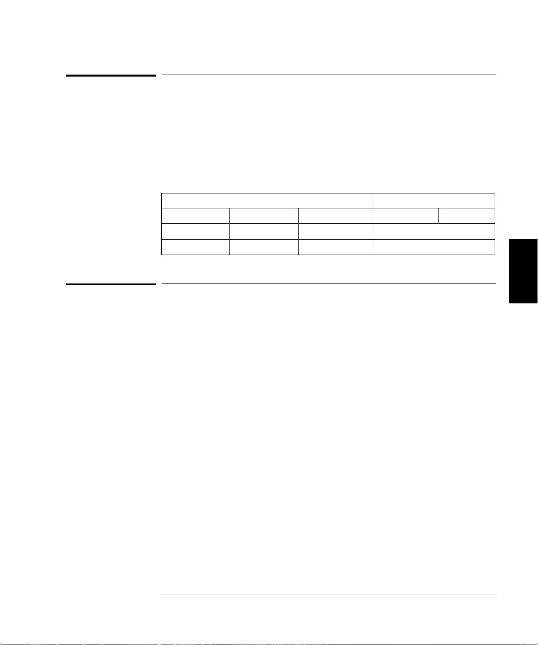
Instrument Requirements Recommended Model Use*
50 W feedthrough load 50 W 0.1 W
6 1/2 digit Digital
Multimeter (DMM)
Thermal Voltage Converter
(50 W termination type)
or
Power Meter
or
Wideband ACrms Meter
Frequency Meter 1 ppm accuracy Agilent 53131A Q,P,T
Oscilloscope 100 MHz Agilent 54624A T
Spectrum Analyzer Response to 90 MHz Agilent 8560EC O
* Q = Quick Verification O= Optional Verification Tests
P = Performance Verification Tests T = Troubleshooting
20 Vdc 0.01%
Integrating ACrms
10 Vacrms 0.1%
1kHz to 15 MHz
100 kHz to 15 MHz
1 VAC rms 0.5%
1 kHz to 20 MHz
Agilent 34401A Q,P,T
3 Volt
Agilent E4418A with
Agilent 8482A
and 20 dB attenuator
—
Q,P,O,T
Q,P
52
Page 55

Chapter 4 Calibration Procedures
Test Considerations
Test Considerations
To ensure proper instrument operation, verify that you have selected the
correct power line voltage prior to attempting any test procedure in this
chapter. See page 22 in chapter 2 for more information.
For optimum performance, all test procedures should comply with the
following recommendations:
Verify the function generator is set to the default power on state
(power on default). A procedure is given on page 41.
Make sure that the calibration ambient temperature is stable and
between 18
Make sure ambient relative humidity is less than 80%.
C and 28 C.
Allow a 1-hour warm-up period before verification or adjustment.
Use only RG-58 or equivalent 50W cable.
Keep cables as short as possible, consistent with the impedance
requirements.
4
53
Page 56

Chapter 4 Calibration Procedures
Performance Verification Tests
Performance Verification Tests
The performance verification tests use the function generator’s
specifications listed in chapter 1, “Specifications,” starting on page 13.
You can perform four different levels of performance verification tests:
Self-Test A series of internal verification tests that give a high
confidence that the function generator is operational.
Quick Verification A combination of the internal self-tests and
Q
selected verification tests.
Performance Verification Tests An extensive set of tests that are
P
recommended as an acceptance test when you first receive the function
generator or after performing adjustments.
Optional Verification Tests Tests not performed with every
O
calibration. These tests can can be used to verify additional instrument
specifications following repairs to specific circuits.
Self-Test
A brief power-on self-test occurs automatically whenever you turn on the
function generator. This limited test assures that the function generator
is capable of operation.
To perform a complete self-test hold down the
Power switch to turn on the function generator; hold down the key for
more than 5 seconds (a complete description of these tests can be found in
chapter 6). The function generator will automatically perform the
complete self-test procedure when you release the key. The self-test will
complete in approximately 5 seconds.
You can perform many tests individually (or all tests at once) using the
TEST command in the SYS MENU. You can also perform a self-test from
the remote interface (see chapter 3 in the Agilent 33120A User’s Guide).
If the self-test is successful, “PASS” is displayed on the front panel.
If the self-test fails, “FAIL” is displayed and the ERROR annunciator
turns on. If repair is required, see chapter 6, “Service,” for further details.
If all tests pass, you have a high confidence (90%) that the function
generator is operational.
54
Shift key as you press the
Page 57

Chapter 4 Calibration Procedures
Performance Verification Tests
Quick Performance Check
The quick performance check is a combination of internal self-test and an
abbreviated performance test (specified by the letter Q in the performance
verification tests). This test provides a simple method to achieve high
confidence in the function generator’s ability to functionally operate and
meet specifications. These tests represent the absolute minimum set of
performance checks recommended following any service activity.
Auditing the function generator’s performance for the quick check points
(designated by a Q) verifies performance for “normal” accuracy drift
mechanisms. This test does not check for abnormal component failures.
To perform the quick performance check, do the following:
Set the function generator to the default power on state (power on default).
A procedure is given on page 41.
Perform a complete self-test. A procedure is given on page 21.
Perform only the performance verification tests indicated with
the letter Q.
If the function generator fails the quick performance check, adjustment or
repair is required.
Performance Verification Tests
The performance verification tests are recommended as acceptance tests
when you first receive the function generator. The acceptance test results
should be compared against the 1 year test limits. After acceptance, you
should repeat the performance verification tests at every calibration interval.
If the function generator fails performance verification, adjustment or
repair is required.
4
55
Page 58

Chapter 4 Calibration Procedures
Frequency Verification
Frequency Verification
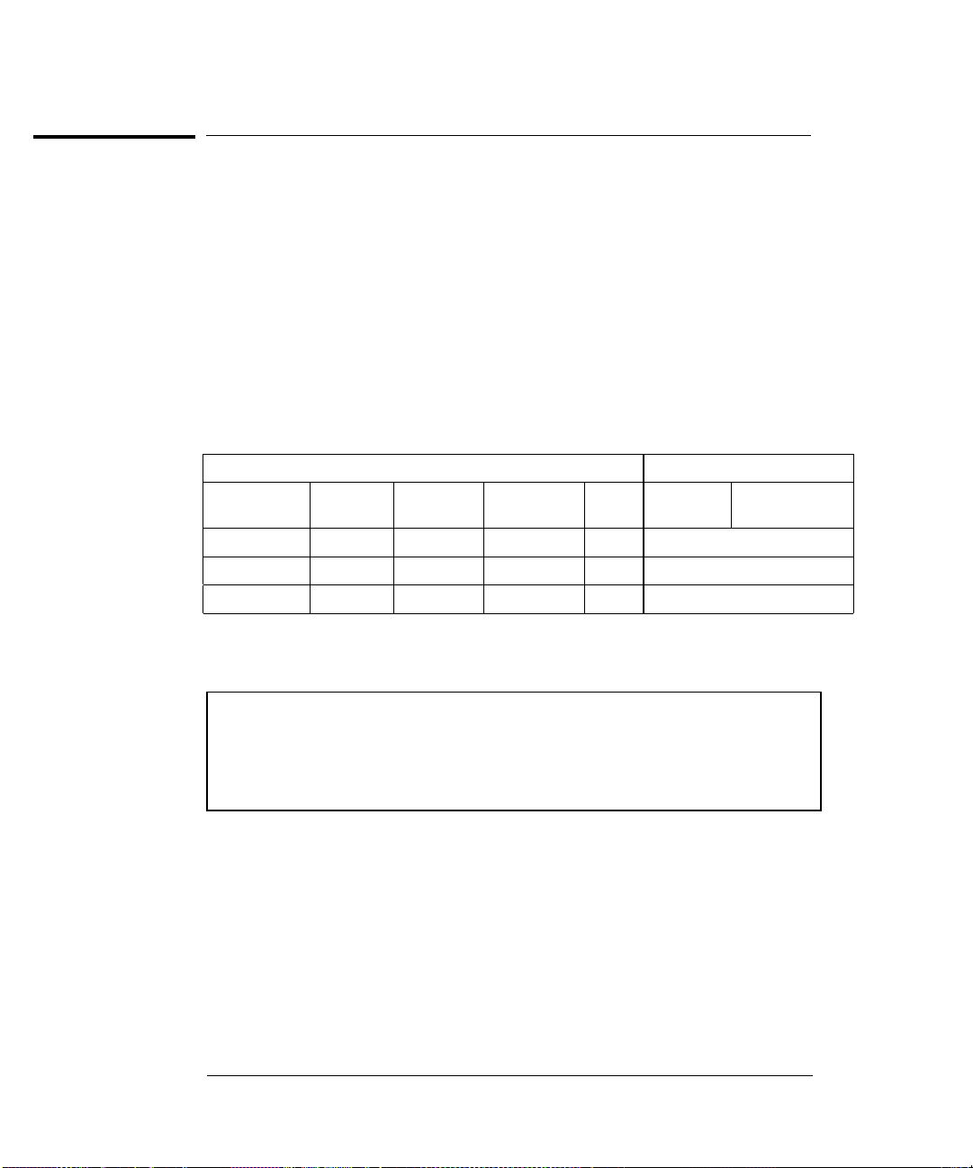
This test verifies the frequency accuracy of the two sources in the
function generator. All output frequencies are derived from a single
generated frequency, and only one frequency point is checked.
The second test verifies the burst rate frequency.
Set the function generator for each output indicated in the table below.
Use a frequency meter to measure the output frequency. Compare the
measured results to the test limits shown in the table. This is a 50
output termination test.
Agilent 33120A Measurement
Function
Q Sine wave
Q Square wave
OUT
TERM
50 W
50 W
1
Ampl Freq
3.5 Vrms 1.00 kHz — — 1.00 kHz
3.5 Vrms 1.00 kHz 500 Hz 1 CYC 500 Hz
BURST
RATE
BURST
CNT
Nominal Error
W
0.02 Hz
5 Hz
Function Gain and Linearity Verification
This test verifies the output amplitude accuracy specification for
sine wave, triangle wave, ramp, and square wave outputs.
Set the function generator for each output indicated in the table below.
Use a DMM to measure the function generator ACrms output voltage.
Compare the measured results to the test limits shown in the table.
This is a HIGH Z output termination test.
Agilent 33120A Measurement
1
Function OUT TERM
Q Sine wave HIGH Z 7.0 Vrms 1.0 kHz 7.0 Vrms
Sine wave HIGH Z 5.7 Vrms 1.0 kHz 5.7 Vrms
Triangle wave HIGH Z 5.7 Vrms 100 Hz 5.7 Vrms
Ramp wave HIGH Z 5.7 Vrms 100 Hz 5.7 Vrms
Q Square wave HIGH Z 10.0 Vrms 100 Hz 10.0 Vrms
Square wave HIGH Z 8.0 Vrms 100 Hz 8.0 Vrms
1
Output termination set using front panel controls. HIGH Z assumes no load on
output. 50W assumes a 50W 0.1W load on output.
56
Ampl Freq Nominal Error
0.07 Vrms
0.057 Vrms
0.057 Vrms
0.057 Vrms
0.1 Vrms
0.08 Vrms
Page 59
Chapter 4 Calibration Procedures
DC Function Offset Verification
DC Function Offset Verification
This test verifies the DC offset and DC output specifications.
Set the function generator for each output indicated in the table below.
Use a DMM to measure the function generator dcV output. Compare the
measured results to the test limits shown in the table. This is a HIGH Z
output termination test.
Agilent 33120A Measurement
Function OUT TERM
Q DC Volts HIGH Z 10.0 Vdc 10.0 Vdc
DC Volts HIGH Z -10.0 Vdc -10.0 Vdc
1
Ampl Nominal Error
0.20 Vdc
0.20 Vdc
AC Amplitude Verification
4
This procedure is used to check the output amplitude calibration of the
function generator. Verification checks are performed to check the
accuracy of the pre-attenuator and post attenuator. Make sure you have
read “Test Considerations” on page 53.
Set the function generator for each output indicated in the table on the
next page. Use a DMM to measure the ACrms output voltage of the
function generator. Compare the measured results to the test limits
shown in the table. This is a HIGH Z output termination test.
1
Output termination set using front panel controls. HIGH Z assumes no load on
output. 50W assumes a 50W 0.1W load on output.
57
Page 60

Chapter 4 Calibration Procedures
AC Amplitude Verification
Agilent 33120A Measurement
Function OUT TERM
Q Sine wave HIGH Z 7.0 Vrms 1.00 kHz 7.0 Vrms
Sine wave HIGH Z 5.7 Vrms 1.00 kHz 5.7 Vrms
Sine wave HIGH Z 5.5 Vrms 1.00 kHz 5.5 Vrms
Sine wave HIGH Z 4.4 Vrms 1.00 kHz 4.4 Vrms
Sine wave HIGH Z 3.5 Vrms 1.00 kHz 3.5 Vrms
Sine wave HIGH Z 2.8 Vrms 1.00 kHz 2.8 Vrms
Sine wave HIGH Z 2.2 Vrms 1.00 kHz 2.2 Vrms
Sine wave HIGH Z 1.7 Vrms 1.00 kHz 1.7 Vrms
Sine wave HIGH Z 1.4 Vrms 1.00 kHz 1.4Vrms
Sine wave HIGH Z 1.1 Vrms 1.00 kHz 1.1 Vrms
Q Sine wave HIGH Z 0.88 Vrms 1.00 kHz 0.88 Vrms
Sine wave HIGH Z 0.70 Vrms 1.00 kHz 0.70 Vrms
Sine wave HIGH Z 0.55 Vrms 1.00 kHz 0.55 Vrms
Sine wave HIGH Z 0.44 Vrms 1.00 kHz 0.44 Vrms
Sine wave HIGH Z 0.35 Vrms 1.00 kHz 0.35 Vrms
Sine wave HIGH Z 0.28 Vrms 1.00 kHz 0.28 Vrms
Sine wave HIGH Z 0.22 Vrms 1.00 kHz 0.22 Vrms
Sine wave HIGH Z 0.17 Vrms 1.00 kHz 0.17 Vrms
Sine wave HIGH Z 0.14 Vrms 1.00 kHz 0.14 Vrms
Sine wave HIGH Z 0.11 Vrms 1.00 kHz 0.11 Vrms
Q Sine wave HIGH Z 0.088 Vrms 1.00 kHz 0.088Vrms
Sine wave HIGH Z 0.070 Vrms 1.00 kHz 0.070 Vrms
Sine wave HIGH Z 0.055 Vrms 1.00 kHz 0.055 Vrms
Sine wave HIGH Z 0.044 Vrms 1.00 kHz 0.044 Vrms
Q Sine wave HIGH Z 0.036 Vrms 1.00 kHz 0.036 Vrms
1
Ampl Freq Nominal Error
0.070 Vrms
0.057 Vrms
0.055 Vrms
0.044 Vrms
0.035 Vrms
0.028 Vrms
0.022 Vrms
0.017 Vrms
0.014 Vrms
0.011 Vrms
0.0088 Vrms
0.0070 Vrms
0.0055 Vrms
0.0044 Vrms
0.0035 Vrms
0.0028 Vrms
0.0022 Vrms
0.0017 Vrms
0.0014 Vrms
0.0011 Vrms
0.00088 Vrms
0.00070 Vrms
0.00055 Vrms
0.00044 Vrms
0.00036 Vrms
1
Output termination set using front panel controls. HIGH Z assumes no load on
output. 50W assumes a 50W 0.1W load on output.
58
Page 61

Chapter 4 Calibration Procedures
AC Amplitude Verification
Install the 50W feedthrough load between the DMM and the function
generator output. Set the function generator for each output indicated in
the table on the next page. Use a DMM to measure the ACrms output
voltage of the function generator. Compare the measured results to the
test limits shown in the table. This is a 50
Function OUT TERM
Q Sine wave
Sine wave
Sine wave
Sine wave
Sine wave
Sine wave
Q Sine wave
Sine wave
Sine wave
Sine wave
Sine wave
Sine wave
Sine wave
Sine wave
Sine wave
Sine wave
Sine wave
Sine wave
Sine wave
Sine wave
Q Sine wave
Sine wave
Sine wave
Sine wave
W output termination test.
Agilent 33120A Measurement
1
Ampl Freq Nominal Error
50 W
50 W
50 W
50 W
50 W
50 W
50 W
50 W
50 W
50 W
50 W
50 W
50 W
50 W
50 W
50 W
50 W
50 W
50 W
50 W
50 W
50 W
50 W
50 W
3.5 Vrms 1.0000 kHz 3.5 Vrms
2.8 Vrms 1.0000 kHz 2.8 Vrms
2.2 Vrms 1.0000 kHz 2.2 Vrms
1.7 Vrms 1.0000 kHz 1.7 Vrms
1.4Vrms 1.0000 kHz 1.4Vrms
1.1 Vrms 1.0000 kHz 1.1 Vrms
0.88 Vrms 1.0000 kHz 0.88 Vrms
0.70 Vrms 1.0000 kHz 0.70 Vrms
0.55 Vrms 1.0000 kHz 0.55 Vrms
0.44 Vrms 1.0000 kHz 0.44 Vrms
0.35 Vrms 1.0000 kHz 0.35 Vrms
0.28 Vrms 1.0000 kHz 0.28 Vrms
0.22 Vrms 1.0000 kHz 0.22 Vrms
0.17 Vrms 1.0000 kHz 0.17 Vrms
0.14 Vrms 1.0000 kHz 0.14 Vrms
0.11 Vrms 1.0000 kHz 0.11 Vrms
0.088Vrms 1.0000 kHz 0.088Vrms
0.070 Vrms 1.0000 kHz 0.070 Vrms
0.055 Vrms 1.0000 kHz 0.055 Vrms
0.044 Vrms 1.0000 kHz 0.044 Vrms
0.035 Vrms 1.0000 kHz 0.035 Vrms
0.028 Vrms 1.0000 kHz 0.028 Vrms
0.022 Vrms 1.0000 kHz 0.022 Vrms
0.018 Vrms 1.0000 kHz 0.018 Vrms
0.035 Vrms
0.028 Vrms
0.022 Vrms
0.017 Vrms
0.014 Vrms
0.011 Vrms
0.0088 Vrms
0.0070 Vrms
0.0055 Vrms
0.0044 Vrms
0.0035 Vrms
0.0028 Vrms
0.0022 Vrms
0.0017 Vrms
0.0014 Vrms
0.0011 Vrms
0.00088 Vrms
0.00070 Vrms
0.00055 Vrms
0.00044 Vrms
0.00035 Vrms
0.00028 Vrms
0.00022 Vrms
0.00018 Vrms
4
1
Output termination set using front panel controls. HIGH Z assumes no load on
output. 50W assumes a 50W 0.1W load on output.
59
Page 62

Chapter 4 Calibration Procedures
Amplitude Flatness Verification
Amplitude Flatness Verification
This test verifies the output amplitude flatness specification at selected
frequencies. If you use a TVC (recommended) or a wide band ACrms
voltmeter (with a 50
described. If you are using a measurement device that requires a transfer
measurement (for example, a power meter), make the transfer in the
reference measurement at 100 kHz.
Set the function generator to the first output indicated in the table below
and make a reference measurement. Select each function generator output
in the table below and adjust the function generator output amplitude until
the measured output is at the reference measurement. Compare the
amplitude level set on the front panel to the test limits shown in the table.
This test is a 50
Function
Q Sine wave
Sine wave
Sine wave
Q Sine wave
Sine wave
Sine wave
Sine wave
Sine wave
Sine wave
Sine wave
Q Sine wave
OUT
TERM
W feed through load), perform this procedure as
W output termination test.
Agilent 33120A Measurement
1
50 W
50 W
50 W
50 W
50 W
50 W
50 W
50 W
50 W
50 W
50 W
Ampl Freq Nominal Error
3.0 Vrms 1.00 kHz <reference>
3.0 Vrms 100.00 kHz <reference>
3.0 Vrms 500.00 kHz <reference>
3.0 Vrms 1.00 MHz <reference>
3.0 Vrms 3.00 MHz <reference>
3.0 Vrms 5.00 MHz <reference>
3.0 Vrms 7.00 MHz <reference>
3.0 Vrms 9.00 MHz <reference>
3.0 Vrms 11.00 MHz <reference>
3.0 Vrms 13.00 MHz <reference>
3.0 Vrms 15.00 MHz <reference>
0.03 Vrms
0.045 Vrms
0.045 Vrms
0.06 Vrms
0.06 Vrms
0.06 Vrms
0.06 Vrms
0.06 Vrms
0.06 Vrms
0.06 Vrms
1
Output termination set using front panel controls. HIGH Z assumes no load on
output. 50W assumes a 50W 0.1W load on output.
60
Page 63

Chapter 4 Calibration Procedures
AM Modulation Depth Verification
AM Modulation Depth Verification
This test verifies the modulation depth specification.
Select each function generator output in the table below. Use a DMM to
measure the function generator ACrms output voltage. Compare the
measured results to the test limits shown in the table. This is a HIGH Z
output termination test.
Agilent 33120A Measurement
AM Modulation
1
Function
Q Sine wave HIGH Z 1.0 Vrms 1.00 kHz Sinewave 100 Hz 0% 0.50 Vrms
Sine wave HIGH Z 1.0 Vrms 1.00 kHz Sinewave 100 Hz 100% 0.61 Vrms
OUT
TERM
Ampl Freq Shape Freq Depth Nominal Error
0.005 Vrms
0.0061 Vrms
4
1
Output termination set using front panel controls. HIGH Z assumes no load on
output. 50W assumes a 50W 0.1W load on output.
61
Page 64
Chapter 4 Calibration Procedures
Optional Performance Verification Tests
Optional Performance Verification Tests
These tests are not intended to be performed with every calibration.
They are provided as an aid for verifying additional instrument specifications.
Square Wave Duty Cycle Verification
This test verifies the duty cycle specification of the squarewave output.
Select each function generator output in the table below. Use an integrating
DMM to measure the Vdc output of the function generator. Compare the
measured results to the test limits shown in the table. This is a HIGH Z
output termination test.
Agilent 33120A Measurement
1
Function
Square wave HIGH Z 1.0 Vrms 300.00 Hz 50% 0.00 Vdc
Square wave HIGH Z 1.0 Vrms 300.00 Hz 25% - 0.50 Vdc
Square wave HIGH Z 1.0 Vrms 300.00 Hz 75% + 0.50 Vdc
OUT
TERM
Ampl Freq
Duty
Cycle
Nominal Error
0.020 Vdc
0.020 Vdc
0.020 Vdc
The DMM used for this test must be an integrating multimeter. If the
first step does not measure 0 Vdc, use an oscilloscope for this test.
Do not use an auto-ranging function on the DMM for this test. Fix the
DMM measurement range at 10 Vdc.
1
Output termination set using front panel controls. HIGH Z assumes no load on
output. 50W assumes a 50W 0.1W load on output.
62
Page 65
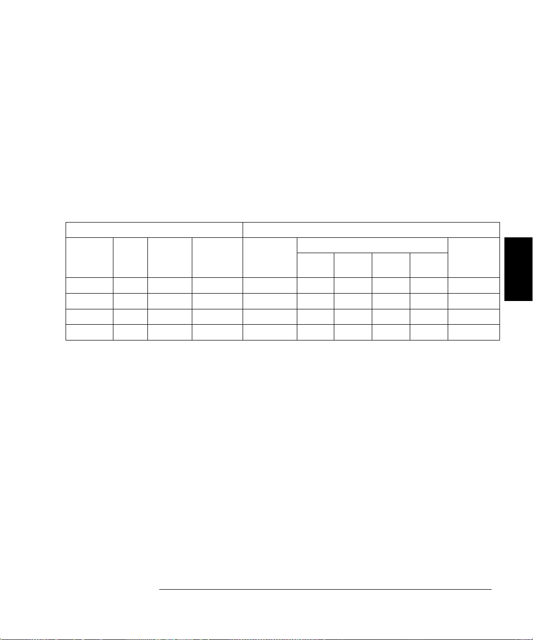
Function
Sine wave
Sine wave
Sine wave
Sine wave
Chapter 4 Calibration Procedures
Optional Performance Verification Tests
Distortion Verification
This test checks the Harmonic Distortion at selected frequencies and
harmonics. This test requires the use of a spectrum analyzer with
dynamic range, frequency range, and resolution bandwidth adequate for
the measurement.
Select each function generator output in the table below. Use a spectrum
analyzer connected to the function generator output. Set the fundamental
frequency reference to 0 dB and measure the 2nd through 5th harmonic
frequencies relative to this reference. This test is a 50
termination test.
Agilent 33120A Measurement
harmonic
1
OUT
TERM
50 W
50 W
50 W
50 W
Ampl Freq Fundamental 2nd 3rd 4th 5th
1.1 Vrms 20.00 kHz reference 40 kHz 60 kHz 80 kHz 100 kHz < 70 dB
1.1 Vrms 100.00 kHz reference 200 kHz 300 kHz 400 kHz 500 kHz < 60 dB
1.1 Vrms 1.00 MHz reference 2 MHz 3 MHz 4 MHz 5 MHz < 45 dB
1.1 Vrms 15.00 MHz reference 30 MHz 45 MHz 60 MHz 75 MHz < 35 dB
W output
Value below
reference
4
1
Output termination set using front panel controls. HIGH Z assumes no load on
output. 50W assumes a 50W 0.1W load on output.
63
Page 66

Chapter 4 Calibration Procedures
Calibration Security Code
Calibration Security Code
This feature allows you to enter a security code (electronic key) to prevent
accidental or unauthorized calibrations of the function generator.
When you first receive your function generator, it is secured. Before you
can adjust calibration constants you must unsecure the function generator
by entering the correct security code. A procedure to unsecure the
function generator is given on page 47.
The security code is set to “HP033120” when the function generator is
shipped from the factory. The security code is stored in non-volatile
memory, and does not change when power has been off or after a remote
interface reset.
To secure the function generator from the remote interface, the security
code may contain up to 12 alphanumeric characters as shown below.
The first character must be a letter, but the remaining characters can be
letters or numbers. You do not have to use all 12 characters but the first
character must always be a letter.
A _ _ _ _ _ _ _ _ _ _ _ (12 characters)
To secure the function generator from the remote interface but allow it to
be unsecured from the front panel, use the eight-character format shown
below. The first two characters must be “HP” and the remaining
characters must be numbers. Only the last six characters are recognized
from the front panel, but all eight characters are required. (To unsecure
the function generator from the front panel, omit the “HP” and enter the
remaining numbers.)
H P _ _ _ _ _ _ (8 characters)
If you forget your security code, you can disable the security feature by
adding a jumper inside the function generator, and then entering a
new code. See the procedure on the following page.
64
Page 67
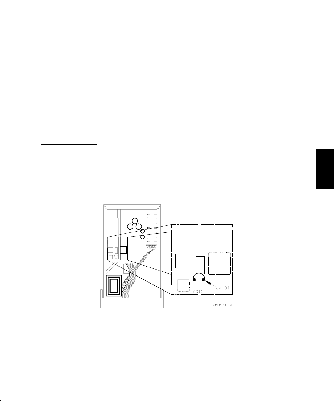
WARNING
Chapter 4 Calibration Procedures
Calibration Security Code
To Unsecure the Function Generator Without the Security Code
To unsecure the function generator without the correct security code,
follow the steps below. A procedure to unsecure the function generator is
given on page 47. Also see “Electrostatic Discharge (ESD) Precautions” in
chapter 6 before beginning this procedure.
SHOCK HAZARD. Only service-trained personnel who are aware
of the hazards involved should remove the instrument covers.
The procedures in this section require that you connect the power
cord to the instrument with the covers removed. To avoid
electrical shock and personal injury, be careful not to touch the
power-line connections.
1 Disconnect the power cord and all input connections (front and rear terminals).
2 Remove the instrument cover. Refer to the disassembly drawing on page 130.
3 Connect the power cord and turn on the function generator.
4 Apply a short between the two exposed metal pads on JM101 (located
near U106 and U205) as shown in the figure below.
5 While maintaining the short, enter any unsecure code. The function
generator is now unsecured.
6 Remove the short at JM101.
7 Turn off and reassemble the function generator.
8 The function generator is now unsecured and you can enter a new
security code. Be sure you take note of the new security code.
4
65
Page 68

Chapter 4 Calibration Procedures
Calibration Count
Calibration Count
The calibration count feature provides an independent “serialization” of
your calibrations. You can determine the number of times that your
function generator has been calibrated. By monitoring the calibration
count, you can determine whether an unauthorized calibration has been
performed. Since the value increments by one for each calibration, a
complete calibration increases the value by approximately 85 counts.
The calibration count is stored in non-volatile memory and does not
change when power has been off or after a remote interface reset.
Your function generator was calibrated before it left the factory.
When you receive your function generator, read the calibration count
to determine its value.
The calibration count increments up to a maximum of 32,767 after which
it wraps around to 0. There is no way provided to program or reset the
calibration count. It is an independent electronic calibration
“serialization” value.
Calibration Message
You can use the calibration message feature to record calibration
information about your function generator. For example, you can store
such information as the last calibration date, the next calibration due
date, the function generator’s serial number, or even the name and phone
number of the person to contact for a new calibration.
You can record information in the calibration message only from the
remote interface. You can read the message from either the front-panel
menu or the remote interface.
The calibration message may contain up to 40 characters. The function
generator can display up to 11 characters of the message on the front
panel; any additional characters are truncated.
The calibration message is stored in non-volatile memory, and does not
change when power has been off or after a remote interface reset.
66
Page 69
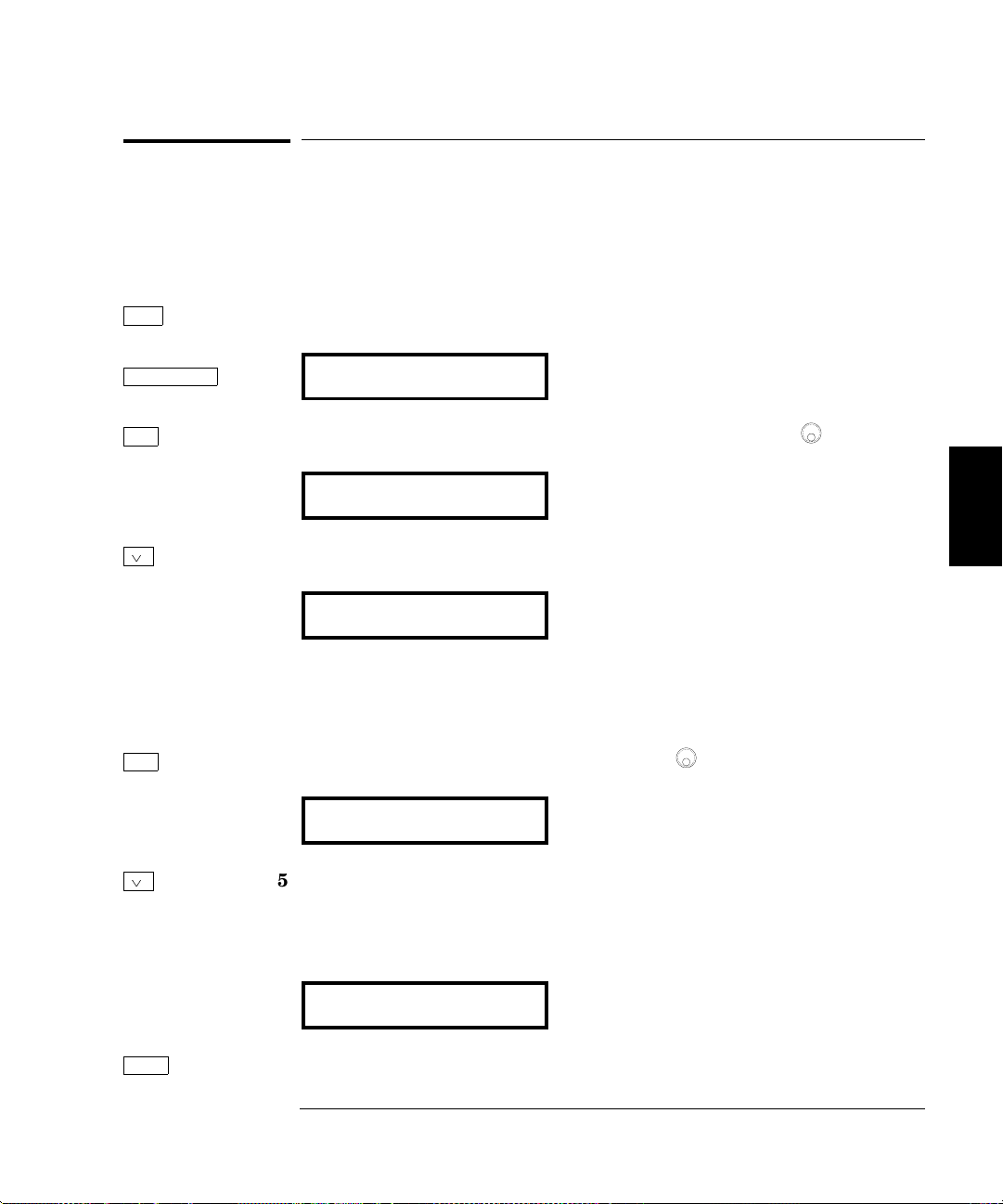
Chapter 4 Calibration Procedures
General Calibration/Adjustment Procedure
General Calibration/Adjustment Procedure
The adjustment procedures described in chapter 4 use the CAL MENU to
generate and set internal calibration constants. The general menu
procedure is the same for all calibration setups. The following example
demonstrates making the Frequency and Burst Rate adjustments.
Shift 1 Turn on the menu.
Menu On/Off A: MOD MENU
< 2 Move across to the CAL MENU choice on this level.
F: CAL MENU
¿ 3 Move down a level to the UNSECURED command.
1: UNSECURED
If the display shows SECURED, you will have to unsecure the function
generator to perform the calibration procedures. A procedure is given on
page 47.
> 4 Move across to the CALIBRATE choice.
1
2: CALIBRATE
¿ 5 Move down one level.
The display indicates the calibration setup number. You can change this
number to perform individual specification adjustments.
1
4
SETUP 00
Enter 6 Begin the Frequency and Burst Rate adjustment procedure.
67
Page 70

Chapter 4 Calibration Procedures
General Calibration/Adjustment Procedure
< > 7 Move the flashing cursor over the digit to be edited.
^
¿ 8 Change the value in the display to match the measured frequency.
1.000,0040KHz
Enter 9 Calculate and save the new value.
CALIBRATING
10 Perform the next adjustment procedure.
The setup number and function generator output is automatically set for
the next adjustment procedure.
SETUP ^01
You will press ENTER twice for each calibration step, once to select
the setup (as described in step 6) and once to enter the adjustment
(as described in step 9).
1
1
You can also use the knob to scroll left or right through the choices on each level of
the menu
68
Page 71
Chapter 4 Calibration Procedures
Aborting a Calibration in Progress
Aborting a Calibration in Progress
Sometimes it may be necessary to abort a calibration after the procedure
has already been initiated. You can abort a calibration at any time by
pressing any front-panel key (except
calibration from the remote interface, you can abort a calibration by
issuing a remote interface device clear message or by pressing the
front-panel
LOCAL key.
Shift-Cancel ). When performing a
Frequency and Burst Rate Adjustment
The function generator stores two calibration constants related to
frequency and burst rate output. The constants are calculated from the
adjustment value entered and are stored at the completion of each setup.
1 Use a frequency meter to measure the function generator output
frequency for each setup in the following table. These adjustments use
a 50
W output termination.
Nominal Output
SETUP FREQUENCY AMPLITUDE
00 * 1.00 kHz 10 Vpp
01 500 Hz 10 Vpp
* A new calibration (SETUP 86 – Rev 4.0) has been added as an alternative to SETUP 00.
The new calibration outputs a 10 MHz sine wave, rather than the 1 kHz signal used for
SETUP 00. The new calibration reduces slew rate dependent errors in the frequency
measurement and is especially important when calibrating the Phase-Lock Assembly
(Option 001). Note that either setup is sufficient to calibrate the carrier frequency and
you don’t need to perform both.
2 Use the CALIBRATE menu to adjust the displayed frequency at each
setup to match the measured frequency and enter the value.
3 Perform the Frequency Verification procedures on page 56.
Adjustment for main frequency
generator, sine wave output
Adjustment for burst rate timing,
pulse output.
4
69
Page 72

Chapter 4 Calibration Procedures
Function Gain and Linearity Adjustment
Function Gain and Linearity Adjustment
The function generator stores six calibration constants related to function
gain and linearity. The constants are calculated from the adjustment
value entered. If the calibration procedure is aborted before all setup steps
have been completed, no calibration constants are stored.
1 Use a DMM to measure the function generator ACrms output voltage for
each setup in the following table. These adjustments use a HIGH Z
output termination.
Nominal Output
SETUP FREQUENCY AMPLITUDE
02 1 kHz 7.07 V rms Adjustment for sine wave gain.
03 1 kHz 5.6 V rms Adjustment for amplitude linearity.
04 100 Hz 5.6 V rms Adjustment for triangle wave gain.
05 100 Hz 5.6 V rms Adjustment for ramp gain.
06 100 Hz 10.0 V rms Adjustment for square wave gain.
07 100 Hz 1.1 Vrms Adjustment for square wave linearity.
2 Use the CALIBRATE menu to adjust the displayed amplitude at each
setup to match the measured amplitude and enter the value.
3 Perform the Function Gain and Linearity Verification procedures on page 56.
AC Amplitude Adjustment (High-Z)
The function generator stores twenty-two calibration constants related to
HIGH Z output, and sixteen calibration constants related to 50
The constants are calculated from the adjustment value entered. The calibration constants are stored following completion of setup 22 (HIGH Z
output) and the calibration procedure may be aborted after that point.
No calibration constants are stored if the procedures are aborted at any
other setup.
1 Use a DMM to measure the function generator ACrms output voltage for
each setup in the following table. These adjustments use a HIGH Z
output termination.
70
W output.
Page 73

Chapter 4 Calibration Procedures
AC Amplitude Adjustment (High-Z)
Nominal Output
SETUP FREQUENCY AMPLITUDE Adjustment for:
8 1 kHz 5.5 V rms 2 dB Output Attenuator
9 1 kHz 4.4 V rms 4 dB Output Attenuator
10 1 kHz 3.5 V rms 6 dB Output Attenuator
11 1 kHz 2.8 V rms 8 dB Output Attenuator
12 1 kHz 2.2 V rms 10 dB Output Attenuator
13 1 kHz 1.7 V rms 12 dB Output Attenuator
14 1 kHz 1.4 V rms 14 dB Output Attenuator
15 1 kHz 1.1 V rms 16 dB Output Attenuator
16 1 kHz 0.88 V rms 18 dB Output Attenuator
17 1 kHz 0.70 V rms 20 dB Output Attenuator
18 1 kHz 0.55 V rms 22 dB Output Attenuator
19 1 kHz 0.44 V rms 24 dB Output Attenuator
20 1 kHz 0.35 V rms 26 dB Output Attenuator
21 1 kHz 0.28 V rms 28 dB Output Attenuator
22 1 kHz 0.22 V rms 30 dB Output Attenuator
23 1 kHz 5.5 V rms 2 dB Pre-attenuator
24 1 kHz 4.4 V rms 4 dB Pre-attenuator
25 1 kHz 3.5 V rms 6 dB Pre-attenuator
26 1 kHz 2.8 V rms 8 dB Pre-attenuator
27 1 kHz 2.2V rms 10 dB Pre-attenuator
28 1 kHz 1.7 V rms 12 dB Pre-attenuator
29 1 kHz 1.4 Vrms 14 dB Pre-attenuator
4
2 Use the CALIBRATE menu to adjust the displayed amplitude at each
setup to match the measured amplitude and enter the value.
3 Perform the AC Amplitude Verification procedures on page 57.
71
Page 74

Chapter 4 Calibration Procedures
Modulation Adjustment
Modulation Adjustment
The function generator stores three calibration constants related to
amplitude modulation depth. The constants are calculated from the
adjustment value entered. If the calibration procedure is aborted before
all setup steps have been completed, no calibration constants are stored.
1 Use a DMM to measure the function generator ACrms output voltage for
each setup in the following table. These adjustments use a HIGH Z
output termination.
Nominal Output
SETUP FREQUENCY AMPLITUDE Adjustment for:
30 1 kHz 3.5 Vrms 0% modulation depth.
31 1 kHz 0.707 Vrms 50% modulation depth.
32 1 kHz 6.36 Vrms 100% modulation depth.
2 Use the CALIBRATE menu to adjust the displayed amplitude at each
setup to match the measured amplitude and enter the value.
33 Perform the AM Modulation Depth Verification procedures on page 61.
NEW CALIBRATION: A new calibration (SETUP 85 – Rev 4.0) has
been added to eliminate a small residual error in the AM amplitude
system which could potentially cause a failure of the AM amplitude
verification. The new calibration operates just like the other AM
calibrations (SETUP 30, 31, 32) in that the external measurement is
AC Vrms with no load. The new calibration is not allowed until the
other AM gain calibrations (SETUP 30, 31, 32) are performed.
The new algorithm is designed such that the calibration should not be
required again once the function generator has been calibrated at the
factory. However, if you change any critical analog components which
determine amplitude in AM modulation, you should perform the
calibration again.
72
Page 75

Chapter 4 Calibration Procedures
AC Amplitude Adjustment (50
W)
AC Amplitude Adjustment (50W)
1 The function generator stores 16 calibration constants related to 50W
output. The constants are calculated from the adjustment value entered.
The calibration constants are stored following completion of setup 49 and
the calibration procedure may be aborted after that point. No calibration
constants are stored if the procedures are aborted at any other setup.
2
Use the DMM to measure the resistance of a 50
Record the measurement for step 3. You can measure the load and cable
resistance (recommended procedure) or just the load as shown below.
W feedthrough load.
4
3 Enter the following setup and use the calibrate menu to enter the
measured value of the 50
will be used to calculate the 50
SETUP LOAD Z
33
Once the value of the 50W load and cable are entered, use the SAME
load and cable for all 50
W feedthrough load (and cable). This number
W output amplitude calibration constants.
Nominal Input
50 W
W tests.
Enter measured value of load.
73
Page 76

Chapter 4 Calibration Procedures
AC Amplitude Adjustment (50
4 Use the DMM to measure the function generator ACrms output voltage
for each setup in the table on the next page. These adjustments use the
50
W load and cable measured in step 2 and connected as shown below.
W)
74
Page 77

Chapter 4 Calibration Procedures
AC Amplitude Adjustment (50
SETUP FREQUENCY AMPLITUDE Adjustment for:
34 1 kHz 3.5 Vrms 0 dB Output Attenuator
35 1 kHz 2.8 Vrms 2 dB Output Attenuator
36 1 kHz 2.23 Vrms 4 dB Output Attenuator
37 1 kHz 1.77 Vrms 6 dB Output Attenuator
38 1 kHz 1.41 Vrms 8 dB Output Attenuator
39 1 kHz 1.12 Vrms 10 dB Output Attenuator
40 1 kHz .887 Vrms 12 dB Output Attenuator
41 1 kHz .704 Vrms 14 dB Output Attenuator
42 1 kHz .559 Vrms 16 dB Output Attenuator
43 1 kHz .442 Vrms 18 dB Output Attenuator
44 1 kHz .350 Vrms 20 dB Output Attenuator
44 1 kHz .281 Vrms 22 dB Output Attenuator
46 1 kHz .223 Vrms 24 dB Output Attenuator
47 1 kHz .177 Vrms 26 dB Output Attenuator
48 1 kHz .141 Vrms 28 dB Output Attenuator
49 1 kHz .112 Vrms 30 dB Output Attenuator
W)
Nominal Output
4
5 Use the CALIBRATE menu to adjust the displayed amplitude at each
setup to match the measured amplitude and enter the value.
6 Perform the AC Amplitude Verification procedures beginning on page 57.
75
Page 78

Chapter 4 Calibration Procedures
DC Output Adjustment
DC Output Adjustment
The function generator stores nine calibration constants related to
DC volts output. The constants are calculated from the adjustment value
entered. The calibration constants are stored following completion of
setup 59. No calibration constants are stored if the procedures are aborted
at any other setup.
1 Use a DMM to measure the function generator dcV output voltage for
each setup in the following table. These adjustments use a HIGH Z
output termination.
Nominal Output
SETUP DC Volts Adjustment for:
50 - 8.0 Vdc Negative offset gain
51 8.0 Vdc Positive offset gain
52 0.0 Vdc AM offset
53 0.0 Vdc 2 dB Pre-attenuator offset.
54 0.0 Vdc 4 dB Pre-attenuator offset.
55 0.0 Vdc 6 dB Pre-attenuator offset.
56 0.0 Vdc 8 dB Pre-attenuator offset.
57 0.0 Vdc 10 dB Pre-attenuator offset.
58 0.0 Vdc 12 dB Pre-attenuator offset.
59 0.0 Vdc 14 dB Pre-attenuator offset.
2 Use the CALIBRATE menu to adjust the displayed output voltage at
each setup to match the measured voltage and enter the value.
3 Perform the DC Function Offset Verification procedures on page 57.
76
Page 79

Chapter 4 Calibration Procedures
Duty Cycle Adjustment
Duty Cycle Adjustment
The function generator stores two calibration constants related to
squarewave offset and two calibration constants related to squarewave
duty cycle. The constants are calculated from the adjustment value
entered. The calibration constants are stored following completion of
setup 63. No calibration constants are stored if the procedures are aborted
at any other setup.
1 Use a DMM to measure the function generator dcV output voltage for
each setup in the following table. These adjustments use a HIGH Z
output termination.
For this test, the DMM must be set to a fixed range capable of measuring
from +10 V to -10 V. Do not use an auto-ranging function for this test.
4
Nominal Output
SETUP FREQUENCY AMPLITUDE
60 — 10.0 Vdc Positive squarewave offset.
61 — -10.0 Vdc Negative squarewave offset.
62 300 Hz 0.0 Vdc 50% duty cycle squarewave.
63 300 Hz 5.0 Vdc 75% duty cycle squarewave
2 Use the CALIBRATE menu to adjust the displayed output voltage at
each setup to match the measured voltage and enter the value.
3 Perform the Squarewave Duty Cycle Verification procedures on page 62.
AC Amplitude Flatness Adjustment
The function generator stores eleven calibration constants related to AC
Amplitude Flatness from 1 kHz to 15 MHz. The constants are calculated
from the adjustment value entered and one of two calculation constants
related to the type of measurement device you are using. The calibration
constants are stored following completion of setup 82. No calibration
constants are stored if the procedures are aborted at any other setup.
77
Page 80
Chapter 4 Calibration Procedures
AC Amplitude Flatness Adjustment
This procedure can be performed with one of three types of measurement
device; a broadband ACrms voltmeter, a power meter, or a thermal
voltage converter. The procedure differs slightly depending upon the type
of measurement device used. These adjustments us a 50
W output termination.
1 Use a DMM to measure the ACrms output voltage of the function generator
and enter the measurement value for the setup in the table below.
Nominal Output
SETUP FREQUENCY AMPLITUDE Reference for:
64 1 kHz 3.0 V rms 1 kHz flatness DAC gain
2a. If you are using a broadband ACrms voltmeter, proceed to step 3.
b. If you are using a power meter capable of measurements at 1 kHz,
use the power meter to measure the function generator output and enter
the value for the setup in the table below. (If your power meter does not
measure to 1 kHz, see the transfer measurement procedure below.)
Nominal Output
SETUP FREQUENCY AMPLITUDE Reference for:
83 1 kHz 3.0 V rms V rms, dBm
Transfer Measurement Procedure
If you are using a power meter not capable of measurement to 1 kHz,
you can perform the transfer measurement at a different frequency.
For example, the Agilent E4418A Power Meter with the Agilent 8482A
probe and 20 dB attenuator are specified to a low frequency of 100 kHz.
To use this measurement device, perform step 1, then use setup 65 to
obtain a 100 kHz output. Measure the output with the power meter and
record the measured value. Perform setup 83 and enter the recorded
value (not a new measurement). Then, perform step 3 (you will use setup
65 twice). This procedure assumes the output of the function generator is
flat from 1 kHz to 100 kHz.
c. If you are using a Thermal Voltage Converter (TVC), use the TVC to
measure the function generator output and enter the measurement for
the setup in the table below (TVC values entered are in mVdc).
Nominal Output
SETUP FREQUENCY AMPLITUDE Reference for:
84 1 kHz 3.0 V rms Thermal Voltage Converter
78
Page 81

Chapter 4 Calibration Procedures
AC Amplitude Flatness Adjustment
3 For each setup in the table below, use the CALIBRATE command to
change the displayed amplitude to match the measured amplitude.
Nominal Output
SETUP FREQUENCY AMPLITUDE Adjustment for:
65 100 kHz 3.0 V rms 100 kHz amplitude flatness
66 500 kHz 3.0 V rms 500 kHz amplitude flatness
67 1 MHz 3.0 V rms 1 MHz amplitude flatness
68 3 MHz 3.0 V rms 3 MHz amplitude flatness
69 5 MHz 3.0 V rms 5 MHz amplitude flatness
70 7 MHz 3.0 V rms 7 MHz amplitude flatness
71 9 MHz 3.0 V rms 9 MHz amplitude flatness
72 10 MHz 3.0 V rms 10 MHz amplitude flatness
73 10.5 MHz 3.0 V rms 10.5 MHz amplitude flatness
74 11 MHz 3.0 V rms 11 MHz amplitude flatness
75 11.5 MHz 3.0 V rms 11.5 MHz amplitude flatness
76 12 MHz 3.0 V rms 12 MHz amplitude flatness
77 12.5 MHz 3.0 V rms 12.5 MHz amplitude flatness
78 13 MHz 3.0 V rms 13 MHz amplitude flatness
79 13.5 MHz 3.0 V rms 13.5 MHz amplitude flatness
80 14 MHz 3.0 V rms 14 MHz amplitude flatness
81 14.5 MHz 3.0 V rms 14.5 MHz amplitude flatness
82 15 MHz 3.0 V rms 15 MHz amplitude flatness
4
4 Perform the Amplitude Flatness Verification procedures on page 60.
Shift Menu On/Off Completion of adjustment procedures. Return the function generator
to the normal operating mode.
EXITING
79
Page 82
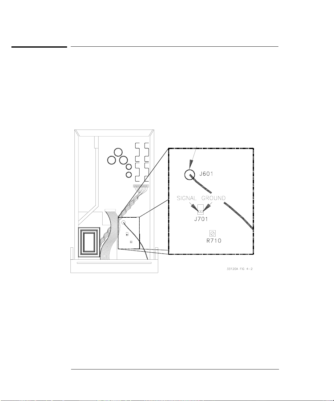
Chapter 4 Calibration Procedures
Output Amplifier Adjustment (Optional)
Output Amplifier Adjustment (Optional)
This adjustment procedure should only be performed following repairs to
the Output Amplifier circuitry. The adjustment improves the high frequency
performance of the Output Amplifier.
1 Remove the function generator power and cover as described on page 130.
2 Use a DMM to measure the ACrms voltage across J701 as shown below.
Cable Shield is
Circuit Ground
3 Turn on the function generator.
4 Set the function generator for a 1 kHz, 1V rms, sine wave output.
5 Adjust R710 for a minimum reading on the voltmeter. Typical readings
are less than 0.005 Vrms.
6 Replace the covers as described on page 130.
80
Page 83

Chapter 4 Calibration Procedures
Error Messages
Error Messages
The following tables are abbreviated lists of function generator’s error
messages. They are intended to include errors which are likely to be
encountered during the procedures described in this chapter. For a more
complete list of error messages and descriptions, see chapter 5 in the
Agilent 33120A User’s Guide.
System Error Messages
Error Error Message
-330 Self-test Failed
-350 Too many errors
501 Isolator UART framing error
502 Isolator UART overrun error
511 RS-232 framing error
512 RS-232 overrun error
513 RS-232 parity error
514 Command allowed only with RS-232
521 Input buffer overflow
522 Output buffer overflow
550 Command not allowed in Local
4
Self-Test Error Messages
Error Error Message
601 Front panel does not respond
602 RAM read/write fail
603 Waveform RAM readback failed
604 Modulation RAM readback failed
605 Serial configuration readback failed
606 Waveform ASIC failed
607 SYNC signal detection failure
608 SYNC signal detection failure
625 I/O Processor not responding
626 I/O Processor failed self-test
627 I/O Processor reset; possible low power line voltage
81
Page 84

Chapter 4 Calibration Procedures
Error Messages
Calibration Error Messages
Error Error Message
701 Cal security disabled by jumper
702 Cal secured
703 Invalid secure code
704 Secure code too long
705 Cal aborted
706 Cal value out of range
707 Cal signal measurement out of range
708 Flatness cal failed
709 Cannot calibrate frequency while externally locked (Option 001)
760 RAM checksum failure
850 Cal setup invalid
851 Negative offset gain cal required (CAL:SETup 50)
852 Flatness DAC gain cal required (CAL:SETup 64)
853 AM cal 1 required (CAL:SETup 30)
854 AM cal 2 required (CAL:SETup 31)
855 Cal load resistance not specified (CAL:SETup 33)
856 Square wave positive offset cal required (CAL:SETup 60)
857 Square wave 50% duty cycle cal required (CAL:SETup 62)
858 AM cal 3 required (CAL:SETup 32)
82
Page 85

5
Theory of
Operation
5
Page 86

Theory of Operation
This chapter is organized to provide descriptions of the circuitry
contained on the schematics shown in chapter 8. A block diagram
overview is provided followed by more detailed descriptions of the
circuitry contained in the schematics chapter.
Block Diagram Overview . . . . . . . . . . . . . . . . 85
Output Attenuator . . . . . . . . . . . . . . . . . . . 86
Output Amplifier . . . . . . . . . . . . . . . . . . . . 87
AM Modulation . . . . . . . . . . . . . . . . . . . . . 89
Pre-attenuator . . . . . . . . . . . . . . . . . . . . . . 90
Square Wave and Sync . . . . . . . . . . . . . . . . . 90
Filters . . . . . . . . . . . . . . . . . . . . . . . . . . 92
Waveform DAC/Amplitude Leveling/Waveform RAM . . 93
Direct Digital Synthesis (DDS ASIC) . . . . . . . . . 95
System DACs . . . . . . . . . . . . . . . . . . . . . . 96
Floating Logic . . . . . . . . . . . . . . . . . . . . . . 97
Earth-Referenced Logic . . . . . . . . . . . . . . . . . 98
Power Supplies . . . . . . . . . . . . . . . . . . . . . 98
Display and Keyboard . . . . . . . . . . . . . . . . . . 100
The self-test procedures are described in chapter 6.
84
Page 87

Chapter 5 Theory of Operation
Block Diagram Overview
Block Diagram Overview
This discussion pertains to the block diagram shown on page 129.
The function function generator’s circuitry is divided into two major
blocks: the floating section and the earth (ground) reference section.
All signal generation, control, and display functions are contained in
the floating section. This section also contains the function generator’s
main CPU.
The floating section can be viewed in two pieces; the analog signal
conditioning section (System DAC, Filters, Sync, Square wave,
Pre-Attenuator, Output Amp, and Output Attenuator) and the digital
logic section (Floating Logic, Digital Waveform Data Synthesis, and
Waveform DAC).
All signal generation, level control, and modulation functions are
performed in the floating section. The waveform DAC generates two
outputs, normal and inverted, between approximately 800 mVp-p and
1 Vp-p. The DAC outputs are routed through anti-alias low-pass filters to
eliminate higher frequency sampling products. The nominal x10 gain of
the output amplifier, combined with preattenuator and output attenuator
settings, are chosen such that the desired output amplitude is produced.
The ground reference section uses a processor configured as a slave to the
main CPU. This processor establishes external I/O communication with
the main CPU through a bi-directional, optically isolated, serial
communications link. The earth referenced processor controls low-level
GPIB (IEEE-488) and RS-232 interface operation. The ground referenced,
rear panel external trigger input uses a dedicated optical isolator to
couple a trigger signal to the main CPU in the floating section.
Separate power supplies are provided for the floating and ground
reference sections. The front panel operates from the floating section with
its logic common different from the CPU logic common.
85
5
Page 88

Chapter 5 Theory of Operation
Output Attenuator
Output Attenuator
Block 8 on block diagram page 129; Schematic on page 138.
The Output Attenuator provides 0 to 30 dB of signal attenuation between
the output amplifier section and the output BNC connector. Output signal
levels are controlled by combining coarse amplitude control from the
output attenuator section and pre-attenuator section with fine amplitude
control from the Waveform DAC AMP_CTL signal.
Four switched output attenuator pads are combined to achieve the desired
signal attenuation as shown in the table below. Relays K801 through
K804 either bypass an attenuator pad or select that attenuator. K801
selects a 2 dB attenuator, K802 selects a 4 dB attenuator, K803 selects
a 8 dB attenuator, and K804 selects a 16 dB attenuator. Relays are
sequenced to provide signal attenuation in 6 dB steps. Intermediate
amplitude levels are controlled by selecting 0 dB, 2 dB or 4 dB of signal
attenuation through the pre-attenuator solid state switches in
combination with reducing the output level of the waveform DAC itself.
The AMP_CTL signal provides smoothly varying control of the Waveform
DAC output level over a 0 dB to -2 dB range. This operation is described
further in the Waveform DAC and System DAC discussions.
Output Attenuation K801 K802 K803 K804
0 dB set set set set
6 dB reset reset set set
12 dB set reset reset set
18 dB reset set set reset
24 dB set set reset reset
30 dB reset reset reset reset
K801 through K804 are latching relays. Their set or reset state is selected
by momentarily pulsing the appropriate coil of the relay. Relay coils are
pulsed with 5 volts for 15 ms through relay drivers U301 and U302.
The main controller, U102, writes data bytes to ASIC U103 which
transmits this data to the relay drivers via the internal 3-wire serial data bus
(SERCLK, SERDAT, and SERSTB) to accomplish the relay state changes.
A 30 MHz filter, composed of L801, C801, and C802, eliminates wideband
noise from the function generator output. The output amplifier and output
attenuators are protected from damage by clamps CR801 and CR802 and
by fuse F801. The function generator is protected from accidental
application of voltages <10 volts for short durations.
86
Page 89
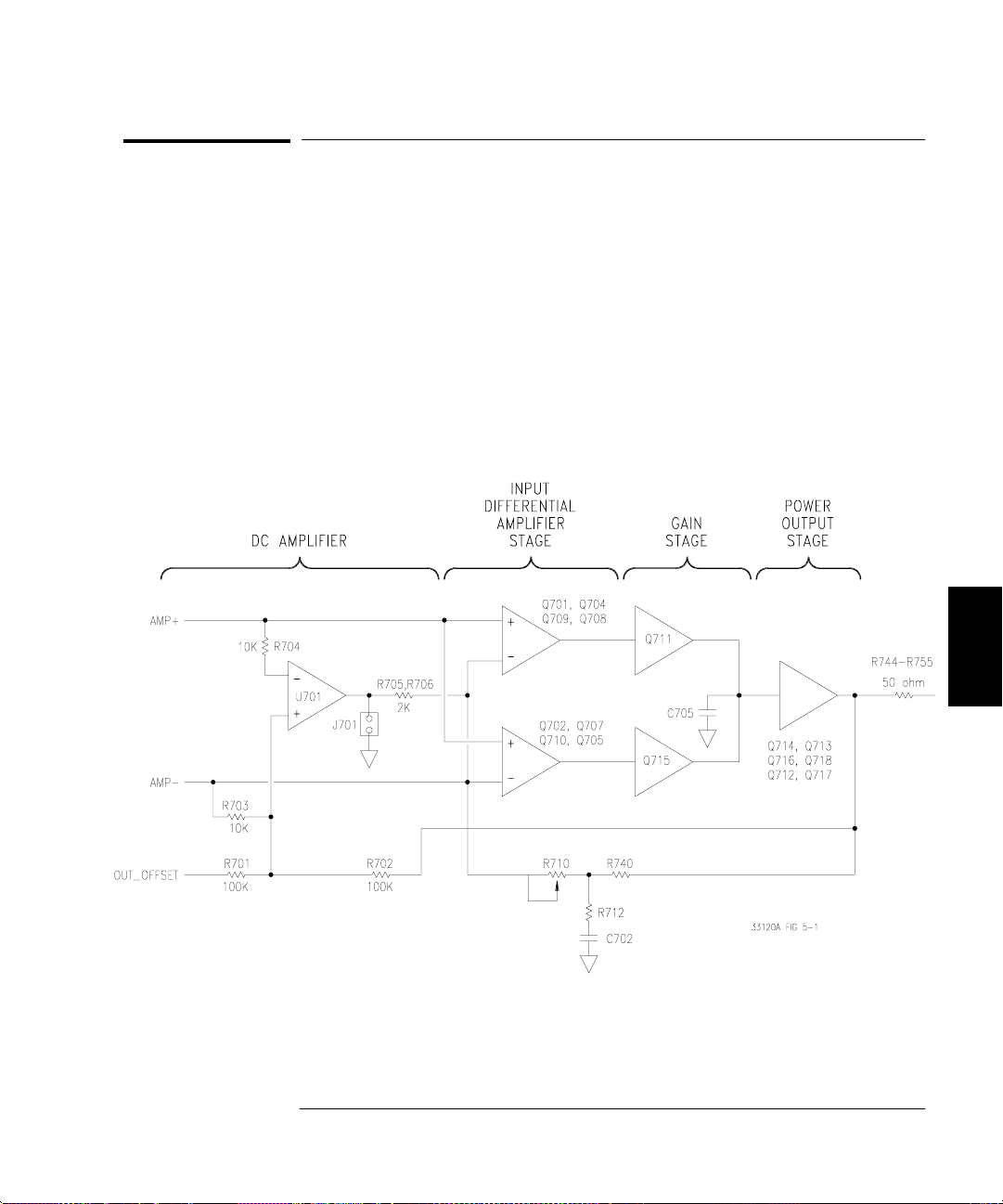
Chapter 5 Theory of Operation
Output Amplifier
Output Amplifier
Block 7 on block diagram page 129; Schematic on page 137.
The output amplifier drives the function generator’s signal output
through the output attenuator section. The output amplifier exhibits an
approximate 35 MHz bandwidth and 1000 V/
originating from the DAC+ and DAC- signal paths are combined at the
input of the amplifier. The output amplifier exhibits a nominal x(-10)
voltage gain from its -AMP_IN input and a nominal x12 voltage gain
from its +AMP_IN input. A dc offset signal, related to the front panel
output offset value, is also summed with the ac signal at the input of the
amplifier. A simplified block diagram of the output amplifier is shown below.
ms slew rate. AC signals
87
5
Page 90

Chapter 5 Theory of Operation
Output Amplifier
The block diagram shows four basic stages: dc amplifier, input differential
amplifier, gain, and power output. The amplifier’s input differential
amplifier stage and gain stage are symmetrical. The +AMP_IN and
-AMP_IN inputs are both amplified through complementary amplifiers
whose outputs are summed together at the input of the power output
stage. Transistors Q701, Q702, Q704 and Q707 form the complementary
input differential amplifiers. Q708 and Q705 are current sources which
provide bias to the input differential amplifiers. Q709 and Q710 are
emitter follower amplifiers used to couple the respective differential
amplifier outputs to the gain stage transistors Q711 and Q715 which
provide virtually all of the amplifiers open loop gain (~ x1000).
The power output stage is a wideband, class C buffer amplifier. Emitter
followers Q714 and Q716 buffer the gain stage output from loading by the
power output emitter follower transistors Q713 and Q718. Idle current
bias for these power output transistors is set by the ratios of R732, R726
and transistor matching between Q713, Q714 and their equivalents in
the other half of the stage: R734, R727 and Q718, Q716. Transistors Q712
and Q717 are current sources which provide bias to emitter followers
Q714 and Q716 respectively.
The low frequency and dc performance of the amplifier is controlled by
U702. This amplifier is used to sense the dc offset present at the
+AMP_IN and -AMP_IN inputs and servo the output amplifier dc offset
to zero volts; to the limit of U702’s own dc offset performance. U702 also
provides a means to add a desired dc offset value into the output signal
path through the x (-1) gain of the OUT_OFFSET signal.
The output amplifier employs a current feedback technique to set the
closed-loop gain. The emitters of Q701 and Q702 are the virtual summing
node points in the amplifier. Amplifier closed loop gain is controlled
predominately by the following ratios:
2 * ( R740 + R710 ) + R717
(
R715 + R716
)
and
2 * ( R740 + R710 ) + R711
(
R719 + R720
)
Variable resistor R710 is used to match the gain through the high frequency
feedback path (described above) and the dc feedback path summed
through resistors R705, R706. The feedback signal current is injected into
the amplifier through the emitters of Q701 and Q702 respectively.
88
Page 91

Chapter 5 Theory of Operation
AM Modulation
AM Modulation
Blocks 3 and 6 on block diagram page 129; Schematics on pages 136 and 133.
Amplitude modulation is performed by analog multiplier U603 combining
the AM_IN and +FUNCTION and -FUNCTION signals. Modulation depths
from 0% to 120% are set by varying the signal at AM_IN.
When the amplitude modulation function is selected, the output of U603
is switched into the +AMP_IN signal path by K602. At the same time,
the -AMP_IN signal path is grounded, cutting the output signal
amplitude in half, to accommodate the more than two times peak signal
levels required by >100% modulation depth.
The AM_IN signal is a combination of any external modulation inputs
applied to the rear panel BNC connector and the internally generated
AM signals. The function generator can internally synthesize an 8-bit
modulation wave shape through DAC U313. Data from any standard or
arbitrary wave shape can be used as the modulating wave shape.
Modulating wave shapes are automatically expanded or compressed in
length, as required, to meet the specified modulating frequency setting.
Changes in the function generator output will lag changes in the
modulating frequency because new modulation data must be computed
and downloaded internally for every frequency change.
The AM_GAIN and AM_OFFSET dc signals are used to calibrate and vary
the am modulation depth settings. AM_GAIN controls the peak-to-peak
output level from U313 in response to modulation depth setting changes.
Likewise, the AM_OFFSET signal varies inversely to the AM_GAIN signal,
as the AM depth setting is varied, to produce a constant signal offset in the
composite AM_IN modulation signal. The net AM_IN offset is independent
of the modulating ac signal component or AM depth setting.
89
5
Page 92

Chapter 5 Theory of Operation
Pre-attenuator
Pre-attenuator
Block 6 on block diagram page 129; Schematic on page 136.
All signals, except square waves, pass through the preattenuator.
The preattenuator multiplexes eight resistive 2 dB attenuators to provide
attenuation from 0 dB to 14 dB in 2 dB steps. The 0 dB, 2 dB, and 4 dB
attenuation steps are used for level settings between the 6 dB steps
selected in the output attenuator section. Amplitude settings between
these 2 dB steps are set by smoothly varying the Waveform DAC output
level from 0 dB to -2 dB of its nominal level via the AMP_CTL signal.
Output attenuator 6 dB steps, preattenuator 0 dB, 2 dB, and 4 dB steps,
and small variations (0 dB to 2 dB) of the Waveform DAC output level
are combined to produce each amplitude setting.
In the preattenuator, U601 and U602 are operated as 8-to-1 multiplexers,
each providing selectable 2 dB attenuation steps. Because of the gain
imbalance of the output amplifier (x 12 on +AMP_IN and x (-10) on
-AMP_IN), the +signal path U601 has an additional 2 dB attenuation
always present (R601 and R602) to equalize the nominal gains in both
the plus and minus signal paths.
Square Wave and Sync
Block 6 on block diagram page 129, schematic on page 136.
During square wave outputs, a sine wave signal is generated internally
and squared-up by comparator U620. Square wave amplitude control is
accomplished by variable gain amplifier Q603 and Q604 and switched
into the output signal path through relay K601. A simplified diagram of
the square wave generator is shown below.
90
Page 93

Chapter 5 Theory of Operation
Square Wave and Sync
Transistors Q601 and Q602 buffer the output of the sine wave anti-alias
filter to the input of comparator U620. Square wave duty cycles are
controlled by the SQ_SYM input on the inverting input of the comparator.
The squarewave outputs of U620 are amplified by variable gain
amplifiers Q603 and Q604.
The amplifier gain output level is controlled by the variable current
source Q605 and U307D in response to the System DAC dc signal
SW_AMP. Squarewave variable gain amplifier output signal levels are
unbalanced by resistors R643 and R644 to correct for the output
amplifier + and - gain differences as discussed in the preattenuator
section on page 90.
Latching relay K601 connects the square wave into the +FUNCTION
and -FUNCTION paths. The relay set or reset state is selected by
momentarily pulsing the appropriate coil. Relay coils are pulsed with
5 volts for 15 ms through relay driver U301. The main controller, U102,
writes data bytes to ASIC U103 which transmits this data to the relay
drivers via the internal 3-wire serial data bus (SERCLK, SERDAT,
and SERSTB) to accomplish relay state changes.
Multiplexer U604 selects one of five sources for the SYNC output: off,
modulation sync, square wave comparator output, RUN*, or Arbitrary
waveform sync. ARB_SYNC is derived from the WA14 line through
U210B. U215B and U210C control the pulse width of the ARB_SYNC
(arbitrary waveform sync) signal. Square wave sync is taken from the
inverting output of square wave comparator U620. U620 also generates
the MOD_SYNC (modulation sync) through U217. Buffer U621 inverts
the sync signal and provides the output current drive to the SYNC output
BNC connector.
91
5
Page 94

Chapter 5 Theory of Operation
Filters
Filters
Block 5 on block diagram page 129; Schematic on page 135.
The output of the Waveform DAC passes through one of two anti-alias
filters. A 17 MHz 9th order elliptical filter is used for the sine wave and
square wave output functions. A 10 MHz 7th order Bessel filter is used
for filtering all other output functions, including all arbitrary waveshapes.
The diagrams below show the typical frequency response of these filters.
The filters are switched in or out of the signal path by latching relays
K501 and K502. Their set or reset state is selected by momentarily
pulsing the appropriate coil of the relay. Relay coils are pulsed with
5 volts for 15 ms through relay drivers U301 and U302. The main
controller, U102, writes data bytes to ASIC U103 which transmits this data
to the relay drivers via the internal 3-wire serial data bus (SERCLK,
SERDAT, and SERSTB) to accomplish these relay state changes. When
K501 and K502 are set, the 10 MHz Bessel filter is selected.
92
Page 95

Chapter 5 Theory of Operation
Waveform DAC/Amplitude Leveling/Waveform RAM
Waveform DAC/Amplitude Leveling/Waveform RAM
Block 4 on block diagram page 129; Schematic on page 134.
The Waveform DAC, U407, converts 12-bit digital data from waveform
RAM’s U404 and U405 into positive and negative analog voltages.
A simplified diagram of the Waveform DAC circuitry is shown below.
The preattenuator, filters, and associated circuits in the output signal path
provide an approximate 25
DAC nominally produces a 40 mA differential output current — yielding
differential 1 Vac output signals. Wave shape (amplitude) data is loaded
into the waveform RAM by the main controller CPU U102. Once loaded,
these data are addressed by the DDS ASIC. The rate at which addresses
are incremented determines the output waveform frequency. Waveform
RAM output data is latched and shifted to ECL levels by U402 and U403
for input to the waveform digital-to-analog converter (DAC) U407. DDS
ASIC U206, waveform data latches U402 and U403, and the Waveform
DAC U407 are clocked at 40 MHz. The 40 MHz clock is generated by
oscillator U413 and ECL level-shifter U401.
W load for the Waveform DAC. The Waveform
93
5
Page 96

Chapter 5 Theory of Operation
Waveform DAC/Amplitude Leveling/Waveform RAM
The Waveform DAC voltage reference is driven by U410B. This reference
controls the magnitude of the nominal 0 to -40 mA DAC output current.
The reference level is varied to produce 0 to -2 dB fine amplitude level
control via dc signal AMP_CTL and
2 dB of dynamic amplitude flatness
correction for static and swept frequency operation via flatness correction
dac U409. These reference voltage adjustments are summed together in
amplifier U410B. Amplitude flatness correction data are stored in
calibration memory during calibration. These data are used to produce a
modulation program with corresponding 8-bit amplitude correction data
values which are gated to latch U412 during operation. These data
provide real-time correction of the output amplitude level as frequency
changes are made. Amplifier U408 and Q401 use the waveform DAC
reference voltage to center the waveform DAC output signal near 0 volts.
U404 and U405 are the high-speed waveform RAM. Together, U404 and
U405 form a 16383 x 12-bit RAM. Each RAM stores and outputs 6 bits of
the waveform DAC 12-bit WD data bus. RAM U404 drives the least
significant 4 bits and U405 drive the most significant 8 bits of the WD
data bus. Note that DAC U407 calls D1 the most-significant bit (MSB)
and D12 it’s least-significant bit (LSB). Waveform RAM addresses are
controlled by the DDS ASIC’s WA (waveform address) bus.
94
Page 97

Chapter 5 Theory of Operation
Direct Digital Synthesis (DDS ASIC)
Direct Digital Synthesis (DDS ASIC)
Block 2 on block diagram page 129; Schematic on page 132.
The DDS ASIC, U206, controls the WA (waveform address) and MA
(modulation address) busses. The waveform address is used by the
waveform RAMs U404 and U405. The modulation data bus is used by the
modulation RAM U205.
The DDS ASIC is comprised of several internal registers and addressing
state machines. Instructions are written to the DDS ASIC by the main CPU
via memory mapped control registers U108 and U202. When loading data
into Waveform RAM or Modulation RAM, addresses on the WA and MA
busses are incremented by ASIC U206. ASIC addresses are incremented
by each rising edge of the TRIG line while writing data into these RAM.
The state of the HOST_RQ* line controls whether the main CPU or the
modulation RAM U205 is sourcing instructions to the DDS ASIC internal
state machines. The Modulation RAM is loaded with frequency values
and amplitude flatness correction values or AM modulation data for latch
U309 and AM dac U313. Data multiplexer U217 and flip-flop U215 are
used to preselect and synchronize the modulation sync source available to
the SYNC output terminal multiplexer U604.
The external trigger input OGEXT is optically isolated by U213 and
applied to an input of trigger source multiplexer U214. The external
trigger input is used for triggering the start of a frequency sweep or
burst output and for externally gating the output signal on and off
asynchronously. U214 selects one of seven trigger sources for use by
U206 for initiating its internal program.
5
95
Page 98
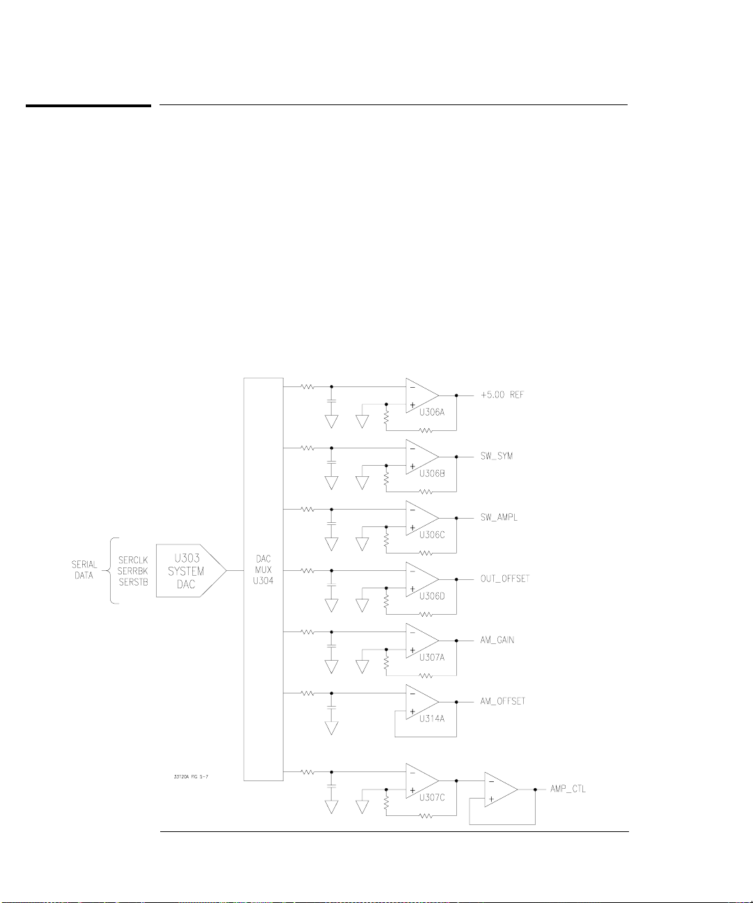
Chapter 5 Theory of Operation
System DACs
System DACs
Block 3 on block diagram page 129; Schematic on page 133.
All output amplitudes are derived from the internal voltage reference of
System DAC U303. The system dac track/hold amplifier outputs are used
to provide controllable bias voltages to various analog circuits including
AM modulation depth, square wave amplitude, square wave duty cycle,
output dc offset, and output amplitude level. The System DAC is
programmed and responds to the main controller via the internal 3-wire
serial data bus SERCLK, SERRBK, and SERSTB. The System DAC is
multiplexed to 7 track/hold amplifiers through U304. Each track/ hold
amplifier is refreshed approximately every 3 ms to maintain its output
setting. Changes to track/hold amplifier outputs are accomplished by
dwelling on that position for an extended period.
96
Page 99

Chapter 5 Theory of Operation
Floating Logic
Floating Logic
Block 1 on block diagram page 129; Schematic on page 131.
The floating logic controls the operation of the entire function function
generator. All output functions and bus command interpretation is
performed by the main CPU, U102. The front panel and earth referenced
logic operate as slaves to U102. The main CPU portion of the floating logic
section is clocked from a 12 MHz ceramic resonator, Y101. Non-volatile
EEPROM U106 stores arbitrary waveform data, calibration constants,
calibration secure code, calibration count, and last instrument state.
The main CPU, U102, is a 16-bit micro controller. The 16-bit A (address)
bus and 8-bit AD (address/data) bus are used to provide digital
communication with the 256k byte program ROM U104, 32k byte RAM
U105, 128k byte non-volatile EEPROM U106, 32k byte high speed
Modulation RAM U205, 16k x 12-bit high speed waveform RAM U404
and U405 and DDS ASIC U206.
Gate array U103 provides CPU address latching and memory mapping
functions. There are four internal registers in U103: a configuration
register, an 8-bit counter register, a serial transmit/receive register, and
an internal status register. RAM chip select signal RAMCE* and CPU
port bits RAMA13 and RAMA14 are used to access 4 - 8k byte banks of
program data RAM. Similarly, 4 banks of 56k non-volatile EEPROM and
2 banks of 56k non-volatile RAM are gated from CPU port bits PRG16,
PRG17, and WAVA16 and U103 signal ROMCE*. Addresses on the CPU
address bus are valid when the ALE line is high. Memory mapping of
control of registers U107 and U202, DDS ASIC U206, data transceivers
U201, U203, U204, and write enables for RAM U404 and U405 and U205
are controlled by data selector U108.
5
The U103 serial register controls the front panel, relay drivers U301 and
U302, and System DAC U303 through a serial data bus. Front panel
signals are FPDI, FPSK*, and FPDO. Interrupts from the front panel are
detected by U103 and signaled to U102 by CHINT. The FPINT line from
U102 signals the front panel that U103 has data to send. The internal
3-bit serial data bus (U102) uses SERCK, SERDAT, and SERSTB to send
data to various registers. SERRBK (serial read back) is used by self test
to verify operation of U103, relay drivers U301, U302, and System DAC
shift register U305.
97
Page 100

Chapter 5 Theory of Operation
Earth-Referenced Logic
The main CPU, U102, communicates with the earth referenced logic
through an optically isolated asynchronous serial data link. U101 isolates
the incoming data (OG_RXD*) from the earth referenced logic. Similarly,
U901 isolates the data from U102 (OG_TXD) to the earth reference logic.
Data is sent in an 11-bit frame at a rate of 187.5 k bits/second. When the
RS-232 interface is selected, data is sent across the serial link at 93.75 k
bits/second. The 11-bit internal data frame is configured for one start bit,
eight data bits, one control bit, and one stop bit.
Earth-Referenced Logic
Block 9 on block diagram page 129; Schematic on page 139.
The earth referenced section provides all rear panel input/output
capability. Microprocessor U903 handles GPIB (IEEE-488) control
through bus interface chip U904 and bus receiver/driver chips U907 and
U908. The RS-232 interface is also controlled through U903. RS-232
transceiver chip U906 provides the required level shifting to approximate
9 volt logic levels through on-chip charge-pump power supplies using
capacitors C904 and C906. Communication between the earth referenced
logic interface circuits and the floating logic is accomplished through an
optically-isolated bi-directional serial interface. Isolator U101 couples
data from U903 to microprocessor U102. Isolator U901 couples data from
U102 to microprocessor U903.
Power Supplies
Block 10 on block diagram page 129; Schematic on page 140.
The power supply section, is divided into two isolated blocks similar to
the floating logic and earth referenced logic sections discussed earlier.
The floating supply outputs are
6 Vrms center tapped filament supply for the vacuum fluorescent display.
All earth referenced logic is powered from a single +5 Vdc supply.
Power-on reset signals are provided by both the floating and earth
referenced power supplies. In addition, the floating section +5 Vdc supply
incorporates a power failure detection circuit which provides a priority
interrupt signal to the main CPU (U102).
98
18 Vdc, +5 Vdc, -5.2 Vdc (VEE), and a
 Loading...