

Page 1

Belt
Switch
Washer,’
Roller
witch,
Circuit
Electronic
valve,
Valve,
Valve,
Levelery
Pump
Switch
Switch,
Fin,
Fin
Belt,
Fuse,
Fuse,
teeper,
Bear,
bear,
king,
fastener,
fear,
fear
ear,
ear,
leeper,
3 ,
jear,
iparing
i
use,
pring,
11
unit,
straight,
roller
bearing
na
,DCCL
flat
assembly
reed
card
component
globe
globe
whiteC-ohe
foot,
reciproca
assembiy
box
round
cartridge
cart.
cart.
slide
worm
worm
retaining
snap
spur
roller,
spur
worm
slide
Spur
worm
dryer
element
assembl
(red)
(blue)
proce
head
(1.6
(400ma
(6.25a
proc
annular
A
310-01-
6525-01-361-8541
5930-01-361-7823
ee
8.9432.
8.9432
\
ŘS
.9452.1090.0
1070.
-1110.4
a
ee
8.9452.1080.2
8.8370.2615.0
8.8966.0067.1
9.8148.6611.0
6.0200.4390.0
6
0200.4490
7.0389.6536.0
7.0451.9608.0
7.0451.9630.0
7.0451.9705.0
7.8185.6023.1
7.8187.6655.1
7.8187.6865.0
7.9402.1129.0
7.94=2.
2022
50
o
대
시
에
에
에
DO)
II
CTA
10
0
N
NU
ten
eta
5999-01-561-7856
5999-01-361-7855
4820-01-361-7817
4820-01-361-7818
6525-01-
4320-01-361-7827
5930-01-361-7866
5930-01-361-7822
53157
5920-01-361-7810
5920-01-561-7811
5920-01-361-7808
5340-01-361-7837
3020-01
3020-01
5365-01
S325-01-361-7824
3020-01
6525-01
“361-7814
AD
-O
73617
01-361-7830
01-
01-361-7836
ο.
-8542
340 - <
!
Page 2

sive,
alve,
eveler,
‘ump
jin,
fin
jear,
unit,
witch
witch,
straight,
eli,
use,
use,
use,
esper,
gar,
ing,
astener,
ear,
pring,
ear
roller
reed
cara
nic
component
giobe
globe
white
foot,
reciproca
assembly
box
rouno
cartriage
cart.
cart.
slide
worm
worm
retaining
snan
spur
rolier,
ето?
ired)
(blue)
proce
head
(1.6
1400ma
(6.258
=
prac
0329
3.8185.6580.1
B.P462.2510.1
8.9462,4546
8.9452.1070.4
8.9432.1110.4
8.9432.1090.0
8.9432.1080.%
8.8370.2615.0
8.8966.0067.1
9.8148.6611
6.0200,4390.
7
7.0451.9608.0
7.0451.9630.0
7.0451.9705.0
7.B185.6023,1
7.8187,6655.1
7.8187.6863.0
7.9402.1129
7.9432.2022.0
.4640
2.2710.0
9200.4490.0
89.6556.0
432.2025.0
ne
RİN
o
mn
pon
a
PS
5999-01-561-7855
4820-01-361-7817
4820-01-361-7818
6525-01-561-8542
4320-01-361-7827
5950-01-561-7866
5950-01-561-7822
5515-01-3561-7850
3030-01-361-78736
5920-01-361-7810
5920-01-361-7811
5920-01-361-7808
5340-01-361-7837
3020-01-361-7844
3020-01-361-7845
5365-01-361-7868
5525-01-561-7824
3020-01-361=
6S25-01-262-8621
WOT
arıng
dryer
element
aonular
Page 3

TABLETOP
CURIX
PROCESSOR
60
OPERATOR'S
INSTALLATION
INSTRUCTION
CURIX
AND
MANUAL
60
ee
АСРА
<>
Page 4
Scope of
this
&
Purpose
manual
Scope
This
Manual
and
operations
maintenance
Purpose
This
Manual
operation
minimum
by a dealer,
SECTION
and
of
2. -
provides
instructions,
is
intended
maintenance
technical
the
Getting
step-by-step
of
the
CURIX®
assistance.
customer
Started.
and
to
provide
may
of
60
an
the
skip
instructions
Processor.
illustrated
an
overview
CURIX
However,
60
SECTION
for
unpacking,
Routine
parts
list
of
the
Processor
if
the
processor
1.
and
set-up,
cleaning
are
installation,
with
proceed
also
a
is
and
included.
installed
to
a
Getting
If
you
encounter
or
if
the
dealer
for
The
SECTION
SECTION
SECTION
SECTION
SECTION
Appendix
Appendix
Appendix
Appendix
Reader’s
Warranty
or
instructions
Manual
Assistance
difficulty
processor
AGFA
1.-
2.-
3.-
4.-
5. - Maintenance
A. - Exploded
B. - Parts
C.-
D.-
Comment
Card
fails to
CORPORATION,
on
“How
consists
of
Unpacking
Getting
Cleaning
Troubleshooting
List
How
To
Equipment
Form
with
the
operate
Agfa
to
get
help
the
following
and
Installation
Started
the
CURIX
Procedures
Views
of
Get
Help
Specifications
installation
as
specified,
Matrix
when
you
Sections:
Procedures
60
Processor
Processor
When
You
or
operating
contact
Division.
need
it.”
Need
It
instructions,
your
Agfa
See
Appendix
C,
©
The information
changes
This
or
please
the
AGFA
100
ATT:
Agfa
information
without
®
Copyright
|
Scope & Purpose
will
publication could
typographical
use
Appendixes,
CORPORATION,
Challenger
Product
Corporation
incurring
1991,
provided
be
incorporated
errors.
the
Postage-Free
or
address
Road,
Manager,
may
you
supply
any
Agfa
Corporation.
of
this
in
this
in
new
inadvertently
If
you
wish
Reader
your
Agfa
Matrix
Ridgefield
Special
use
and
distribute
in a way
obligation
manual
All
rights
whatever.
Manual
comments
Products
it
reserved.
is
editions
contain
to
comment
Comment
Division
Park,
believes
subject
NJ
Group
any
appropriate
to
of
this
technical
on
Form
to:
07660
of
the
change.
publication.
inaccuracies
this
located
Such
publication,
after
a
ui
Page 5
Table
of
Contents
Introduction
SECTION
1.1
1.2
1.3
1.4
SECTION
2.1
2.2
2.3
2.4
2.5
2.6
2.7
2.8
2.9
SECTION
Each
Each
Each
©
3.1
1.
Unpacking
Working
Basic
Unpacking
Optional
Components
Operating
Processor
Clean
Checking
Standard
“Quick”
Mixing
Start-up
Day.
Wee!
Month.
Removing
Area
Installation
Fixed
2.
Getting
Controls
the
Tanks
the
Replenishment
Replenishment
the
Procedures
3.
Cleaning
and
Requirements..
Requirements
the
CURIX
Water
of
the
Functions
Before
Current
Developer
Cleaning
and
Installation
60
Processor
Connection
Started
CURIX
...
Adding
Replenishment
Rate
Rate
and
Fixer
.....
the
CURIX
of
Accessory
60
Processor
Chemicals
Adjustment.
Adjustment
Chemicals
60
Processor
the
Tanks
Procedures
...
Rate
.
Procedure
.
.
SECTION
4.1
4.2
4.3
4.4
4.5
SECTION
5.1
5.2
-5.3
5.4
5.5
APPENDIX
APPENDIX
APPENDIX
APPENDIX
Reader's
4.
Troubleshooting
Processor
Film
Film
Appearance
Excessive
Replacement
Replacement
Maintenance
Replacement
Replacement
Fails
Transport
Drying
Problems
Replenishment......
5.
Maintenance
A.
Exploded
B.
Parts
C.
How
D.
Eguipment
Comment
to
Operate - Power
Failure - Power
of
Processed
of
Fuses.
of
Defective
of
the
Main
of
Springs...
of
Dryer
Guide
Views
Lis:
to
Get
Specifications
Form
Checklist
Switch
Film
Procedures
Gears
.
Drive
Assembh
Plate
of
Processor
Help
When
Switch
Keepers....
You
is
On
Need
is
On.
....
....
It
Table
of
Contents
Page 6

Introduction
The
cal
to
It
O
Q
Q
|
Q
Q
Q
Q
Q
CAUTION:
read
CURIX
features
the
features:
Easy
Low
Rapid
Precise
High-efficiency
mum
Simplified,
resistant
Handles
Processing
60
Tabletop
of
high-capacity
highest
SECTION
standards
installation — just
operating
start-up
control
of
excess
rackless
rollers
film
time,
Processor
Agfa
Film
of
quality
plug
it
in
cost - economical
time - only 7 minutes
of
temperature
modular
heat - no
from
4" x 4"
dry-to-dry
Before
1
carefully.
film
transport
you
and
infrared
venting
up
to
14"
in
only 3 minutes
unpack
incorporates
Processors.
and
reliability.
stand-by
chemistry
dryer
is
needed
system
wide
for
rapid drying
with
and
the
processor
mode
many
of
the
It
is
manufactured
replenishment
with a mini-
chemical
36"
long
please
technologi-
|
CURIX
60
Introduction
1
6
Page 7

v
SECTION
Unpacking
and
Procedure
1.1
Requirements
NOTE:
processor,
darkroom
working
installation
Installation
Working
Before
make
which
area
and
requirements.
1
Area
unpacking
sure
you
has
an
adequate
meets
the
the
have
basic
a
The
CURIX
The
counter
must
have a minimum
leveling
is
Top
FZ3H2003)
feet
recommended
Extension
60
or
are
are
Processor
support
approximately
for
(Cat.
available
upon
working
safety
No.
F8AM4440)
as
LIGHT
is
x
;
(am
i
designed
which
purposes.
accessories
COVER
to
the
surface
23"
COUNTER
of
apart.) A larger
or
Processor
224 一 一
MINIMUM
26" x 26"
be
installed
processor
26" x 26"
If
needed, a suitable
from
Agfa
SIZE
in a darkroom.
is
to
(the
working
Stand
Corporation.
本
一
be
一
set
up
centers
surface
Counter
(Cat.
No.
|
of
the
Figure
The
certain
Q
Q
Q
1.
Dimension
processor
minimum
Full
access
Minimum
Minimum
should
from
clearance
clearance
===
=-
Drawing
be
accessible
clearance
front
rear,
above
for
must
of
processor
left
counter
37
Processor
from
be
provided
and
right
all
top:
y
Π
Installation
sides
if
for
use.
side:
1"
28"
IS
possible,
As
follows:
but
Section
1:
Unpacking
and
Installation
Procedures
7
Page 8

1.2
Basic
Requirements
Installation
Complete
APPENDIX
Power
outlet
Water
water
should
nient sink
bottle,
Disposal
specifications
Requirement:
is
required.
Requirement:
connection.
be
and
mixing
of
WARNING:
to
local
codes
Care
should
Please
chemistry
from
Ventilation
does
sive
normal
Agfa
not
external
operator
observe
require a separate
D.
The
following
Water
at
normal
Waste
labels.
Corporation.
Requirement:
heat.
water
the
chemicals
It
is
regarding
be
taken
Therefore,
comfort
room
Chemistry
the
for
the
are the
120
VAC,
The
CURIX
is
supplied
temperature
hose
is
recommended
and
the
purchaser’s
when
hazard
Material
The
exhaust
for
short
CURIX
basic
60
Hz,
60
Processor
by a water
cleaning
and
Waste
the
disposal
handling
instructions
Safety
Infrared
system
the
only
periods.
60
Processor
requirements
1100 W max.
does
replenisher
(59º
to
77º
F)
for
filling
the
processor.
Water:
responsibility
of
waste
chemistry
provided
Data
Sheets
Dryer
in
the
and
does
darkroom
ventilation
are
provided
for
installation:
Grounded,
not
need a separate
However, a conve-
the
water
to
chemistry.
at
are
CURIX
not
60
produce
required
in
15
bottle.
replenisher
conform
all
times.
on
the
available
Processor
Amp
Water
exces-
is
for
The
processor
and
86º
F,
and a relative
Darkroom
package
After
is
closed,
Lighting
for
exposed
the
will
operate
Reguirement:
recommended
film
is
inserted
darkroom
properly
humidity
darkroom
into
door
may
at a room
between
Consult
lighting
the
processor
be
opened.
temperature
25%
and
the
medical
conditions.
and
between
80%.
imaging
the
Light-tight
film
Cover
59°
F
Section
1:
Unpacking
and
Installation
Procedures
Page 9
1.3
CURIX
Unpacking
Processor
60
the
|
|
following
By
plastic
the
opened
You
have
items:
the
wrapper,
small
the
also
preliminary
lifted
carton
inner
verified
that
unpacking
large
the
obtain
to
you
have
instructions
carton
cover
manual.
this
received
from
the
following
you
the
removed
have
pallet,
standard
and
|
|
Remove
The
number
Remove
as
Lift
|
The
|
surface
|
CAUTION:
|
processor
remove
Tray/Cover
|
The
CURIX
Six
Three
Three
Adapter
Light-tight
And,
Waste
Agfa
Specific
shown
60
Processor
replenisher
bottle
valves
caps
for
hose
accessory
Cover
if
ordered,
bottles
Developer
type,
size,
Polyfoam
processor
Processor
processor
as
pallet & packaging
of
polyfoam
the
polyfoam
in
Figure
shown
since
the
is
onto
may now
It
tape
at
bottles
replenisher
(drain)
Accessory
the
following
and
Fixer
concentrate
and
quantity
Protective
protected
sheets.
2.
in
Figure
is
it
holding
this
by
sheets
Work
Surface
be
lifted
3.
recommended
weighs
time.
components
bottles
optional
of
Agfa
Packing
large
rigid
and
slide out
and
placed
approximately
the
processor
may now
accessories:
solutions
Film
polyfoam
the
rigid
in
position
that
two
Receiving
be
discarded.
supports,
polyfoam
on
people
120
Ib.
and
supports
the
work
lift
the
Do
a
not
NOTE:
Drain
Hoses
Developer
Water
(white).
color
coded,
each
Drain
Then,
lower
operating
The
order
from
(red),
Fixer
If
they
place a mark
Hose
for
the
processor
position.
of
the
three
left
to
right are:
(blue),
and
are
not
on
identification.
to
|
Disengage
Lift
three Drain
Hoses
ber
|
Unpack
If
cartons
|
Arrange
Arrange
Water
be
|
Waste
|
Section
the
processor
are
bands
the
you
have
and
the
Hoses
inserted
Bottles
1:
Unpacking
the
Hoses.
held
and
(optional)
ordered
place
the
Hoses
Drain
are
into
Drain
and
Do
in
place
withdraw
the
near
Hoses
inserted
the
second
may
be
and
Hoses
set
it
down
not
use
by
two
rubber bands.
the
Drain
Waste
optional
the
used.
Installation
Bottles
processor.
as
shown
into
one
Waste
on
its
the
legs
Hoses
Waste
in
Waste
Bottle.
Procedures
rear
as a pivot
as
shown
Bottles,
Figure
5.
Bottle.
Optionally,
end
to
gain
Carefully
in
remove
Developer
The
access
point.
remove
Figure
them
Fixer
three
to
The
Drain
the
4.
from
and
Waste-
Hose
should
separate
the
rub-
their
Page 10

Figure
2.
Remove
Polyfoam
Protective
Packing
Figure
4.
Disengage
Drain
Hoses
©
e
Hoses
Figure
3. Lift
Processor
onto
Work
Surface
Figure
Arrangement
5.
of
Section
1:
Unpacking
and
Installation
Procedures
Page 11

NOTE:
delivered
attached
permit
them
the
processor
any
of
the
If
necessary,
Clamps
Unions.
retighten
See
to
Afterwards,
Figure
The
processor
with
Elbow
to
the
Drain
to
pass
for
four
sides.
open
reposition
the
Hose
6.
Unions
Hoses
underneath
draining
the
Hose
the
carefully
Clamps.
is
to
from
Elbow
—
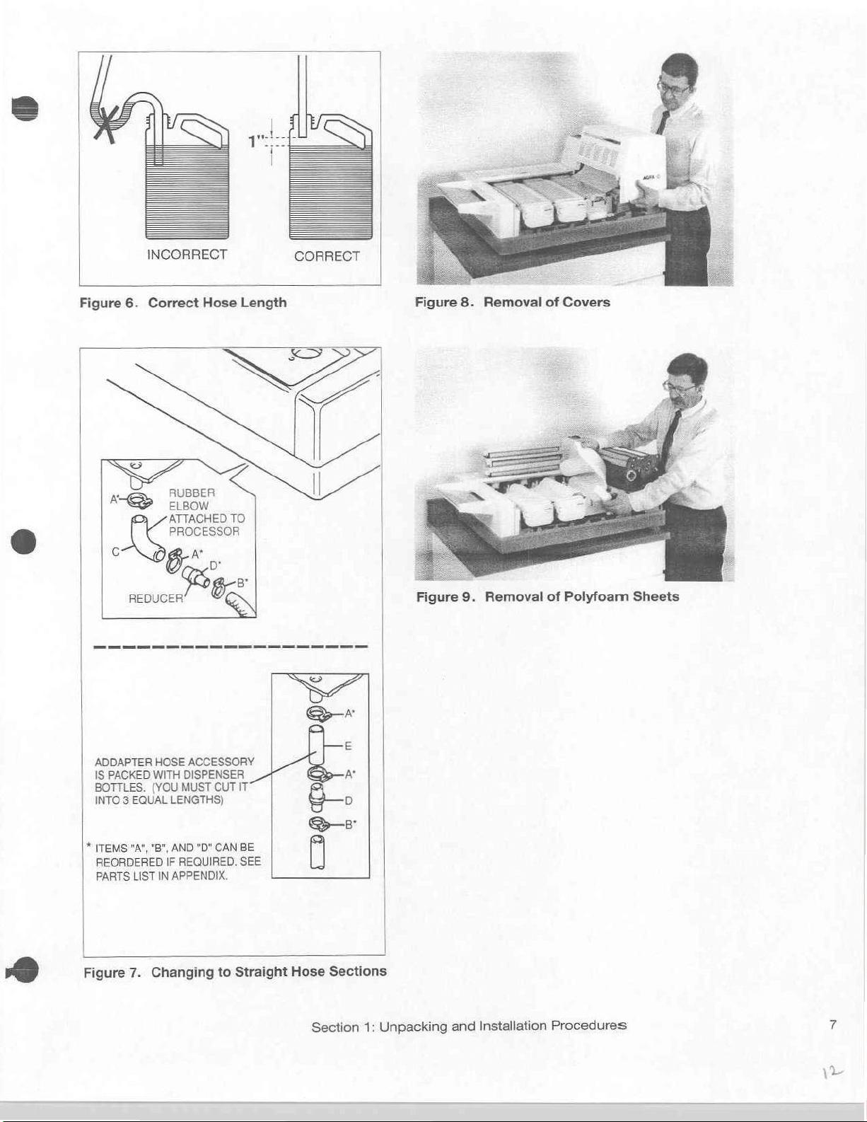
CAUTION:
cals,
shown
Hose
of
solution.
If
|
stored
|
Hoses
If
opening
2
To
replaced
for
change.
To
1.
2.
3.
4.
the
in
length
space
the
processor
beneath,
passed
the
processor
is
already
straighten
with
this
purpose.
Change
Loosen
Remove
Cut
Attach
Drain
Adapter
in
in
Drain
Figure
should
between
is
holes
through
is
the
straight
to
Straight
Hose
Elbow
Hose
place
order
Hoses
to
to
provided
Drain
See
Union
of
to
prevent
must
6.
Hose
be
cut
its
end and
be
installed
should
to
the
mounted
for
Hoses
sections. A length
Figure 7 for
Hose
clamps
“C”
and
“E”
into
Elbow
Unions
be
installed
ends
should
to
provide
the
on a counter
be
cut
into
Waste
Bottles.
on the
the
Drain
the
rubber
instruction
Sections
“A"
and
Reducer
three
equal
and
back-up
highest
the
CURIX
Hoses.
Elbow
of
Adapter
“B".
“D”.
lengths.
reclamp.
of
used
without
not
be
submerged.
approximately
level
with
the
Waste
counter
Processor
on
top
Unions
Hose
making
Stand,
must
chemi-
dips
of
and
is
this
as
1
inch
waste
Bottles
the
Drain
an
be
provided
simple
Removal
Remove
Lift
off
the
as
shown
Lift
the
remove
small
rectangular
of
Covers
tape
that
Receiving
in
Figure
covers
the
polyfoam
is
from
polyfoam
and
Removal
securing
Tray/Cover
8.
The
Dryer
the
Developer,
sheet
as
cushion
the
Receiving
first,
Section
Fixer,
shown
of
Polyfoam
and
and
in
Figure
next
to
Sheets
Tray/Cover.
then,
the
Cover
lifts
Wash-Water
9.
the
Wash-Water
See
Dryer
straight
Also,
remove
Figure
Section
up.
Tanks
the
Tank.
3.
Cover
and
Section
1:
Unpacking
and
Installation
Procedures
Page 12
INCORRECT
CORRECT
Figure
。
A
G
6.
Correct
REDUCER
Hose
RUBBER
ELBOW
ATTACHED
PROCESSOR
в:
TO
А*
Peg
Length
Figure
Figure
8.
9.
Removal
Removal
of
Covers
of
Polyfoam
Sheets
ADDAPTER
|
IS
PACKED
BOTTLES.
INTO 3 EQUAL
*
ТЕМ$
REORDERED
PARTS
"А",
LIST
HOSE
WITH
(YOU
LENGTHS)
"В",
АМО
IF
IN
APPENDIX.
ACCESSORY
DISPENSER
MUST
"О"
REQUIRED.
Figure
7.
Changing
CUT
IT
CAN
BE
SEE
to
Straight
Hose
Section
Sections
1:
Unpacking
and
Installation
Procedures
Page 13

NOTE:
be
level
replenishment
Leveling
make
wise
counter-clockwise
processor,
made
the
appropriate
for
screws
this
adjustment.
to
raise
easier
The
processor
proper
operation
of
chemistry.
are
provided
the
processor.
to
Turning
by
lifting
the
corner.
lower
slightly
must
and
Turn
clock-
Turn
the
screws
to
on
is
|
Replace
Developer
Section
e
Level
Place
clockwise
Level
Place
sor
the
Cover,
the
the
the
the
left-to-right.
Tank
Covers.
(red),
Fixer
(blue),
and
the
Processor
builder's
or
counter-clockwise
Processor
level
as
Front-to-Back
level
Left-to-Right
shown
They
are
Water
Receiving
as
shown
to
in
Figure
color
coded
(white.)
Tray/Cover.
in
level
11 to
Next,
Figure
the
adjust
10.
processor
for
replace
Turn
the
easy
identification;
the
Dryer
the
leveling
front-to-back.
level
of
the
s
screw
proces-
Unpack
Open
out
Install
Slide
firmly
|
Insert
Two
also
valves
bottle
Water
Select
receptacles
empty
Fully
The
Figure
the
Light-tight
the
carton
vertically
the
into
sets
contained
to
as
the
Light-tight
Light-tight
position
the
Dispenser
of
Dispenser
the
attached.
avoid
contamination
(white.)
the
at
Never
Dispenser
in
the
this
time.
shown
Assembled
fully
assembled CURIX
15.
Cover
containing
in
Figure
Cover
Cover
as
shown
Bottles
Bottles
Operator’s
The
color-codes
interchange
Bottles
Bottle
Holder
CURIX
60
the
Light-tight
12.
Accessory
Accessory
in
are
Manual.
of
with
onto
Figure
13.
packaged
match
chemistry.
the
valves.
valves
as
shown
Processor
60
Processor
Cover
the
One
them
and
in
should
Accessory
Feed
in
the
small
of
the
sets
to
their
Developer
place
them
Figure
14.
appear
and
Tray
and
press
carton
has
corresponding
(red),
into
The
as
which
color-coded
Fixer
their
bottles
shown
lift
it
(blue),
are
in
@
Section
1:
Unpacking
and
Installation
Procedures
Page 14
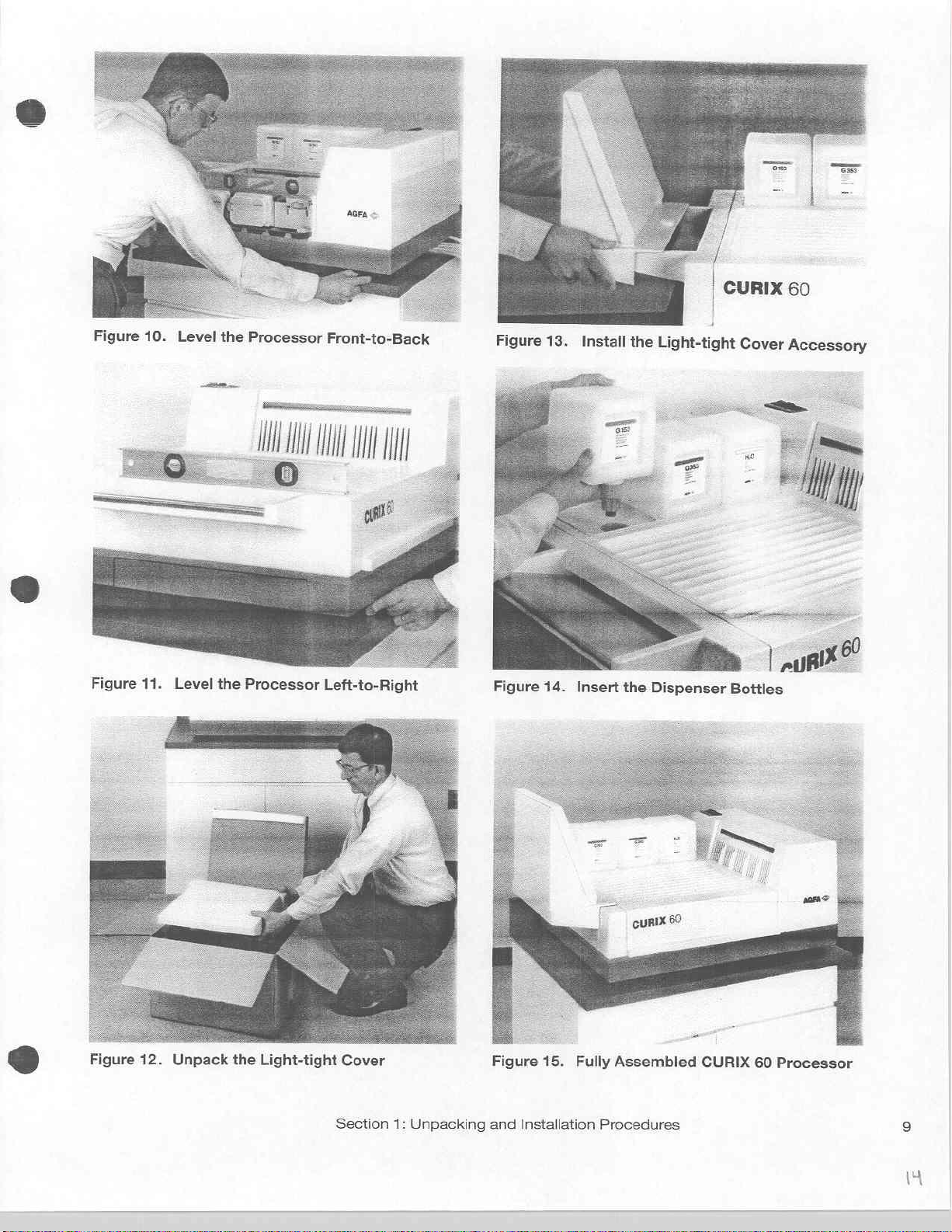
Figure
11.
Level
the
Processor
Left-to-Right
Figure
14.
Insert
the
Dispenser
Bottles
Figure
12.
Unpack
the
Light-tight
Cover
Section
1:
Unpacking
Figure
and
Installation
15.
Fully
Procedures
Assembled
CURIX
60
Processor
Page 15
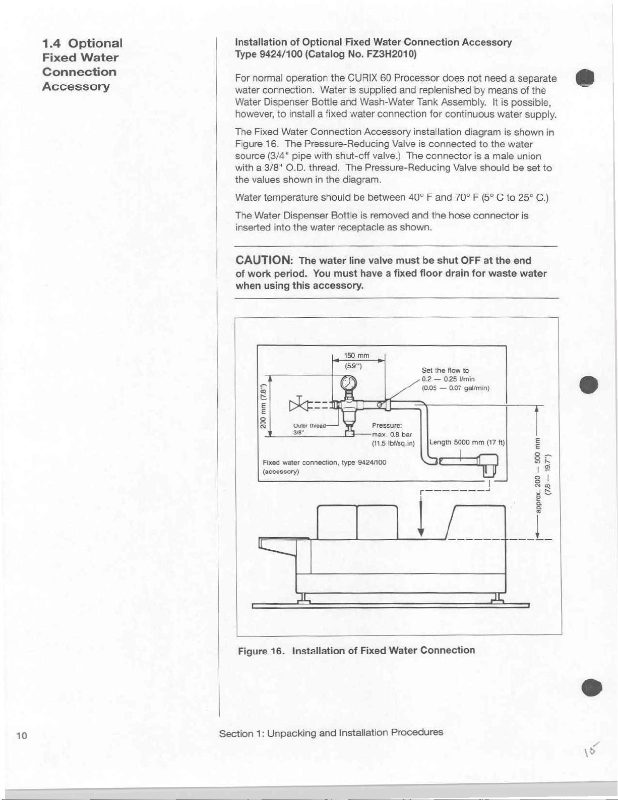
1.4
Optional
Fixed
Connection
Accessory
Water
|
Installation
Type
For
water
Water
however,
The
Figure
source
with a 3/8"
the
Water
The
inserted
of
Optional
9424/100
normal
connection. Water
Dispenser
Fixed
16.
(3/4"
values
temperature
Water
into
(Catalog
operation
Bottle
to
install a fixed
Water
Connection
The
Pressure-Reducing
pipe
with
O.D.
thread.
shown
Dispenser
the
in
should
water
Fixed
No.
the
CURIX
is
and
water
shut-off
The
the
diagram.
be
Bottle
receptacle
Water
FZ3H2010)
supplied
Wash-Water
Accessory
valve.)
Pressure-Reducing
between
is
removed
Connection
60
Processor
and
replenished
Tank
connection
installation
Valve
is
The
40° F and
and
as
shown.
for
connected
connector
the
Accessory
does
not
by
Assembly.
continuous
diagram
to
is a male
Valve
should
70° F (5° C to
hose
connector
need a separate
means
the
It
is
possible,
water
is
water
of
the
supply.
shown
union
be
set
25°
is
in
to
C.)
68
CAUTION:
of
work
period.
when
using
(789
mm
200
」
|
Fixed
(accessory)
Cai
The
You
this
accessory.
water
connection,
water
must
type
line
valve
must
have a fixed floor
150
mm
593
Pressure:
max.
0.8
bar
(115
Ibí/sg.in) | [Length
9424/100
be
shut
OFF
drain
Set
the flow
02 — 025
(005 一 0.07
to
ilmin
gal/min)
5000
for
mm
at
the
waste
(17
ft)
end
water
Е
8 =
¡$
e
8
Na
хе
è
|
10
Figure
16.
Installation
of
Fixed
Section
1:
Unpacking
and
Installation
Water
Connection
Procedures
Page 16

SECTION
Getting
2.1
Components
CURIX
Before
the
a
few
yourself
See
60
attempting
CURIX
moments
with
Figure
2
Started
Processor
to
60
Processor,
to
familiarize
its
components.
17.
of
operate
take
the
TRANSPORT
ROLLERS
(2
REPLENISHMENT
PUMPS
©
BOTTLE
HOLDER
DISPENSER
BOTTLES
©
REAR
TRANSPORT
DRYER
GUIDE
PLATES
TANK
HEATERS
e
Shown
with
Figure
Figure
Exposed
processor
The
ment
and
After
Receiving
17.
Components
18
shows a functional
film
is
or
through
film
first
passes
and
dryer
Wash-Water
drying,
the
Tray/Cover.
TANK GUIDE
PLATES
© ©
Receiving
inserted
the
the
systems
Tanks,
film
and
exits the
TANK
‘COVERS
Tray/Cover
of
directly
Light-tight
Film
and
and Dryer
the
CURIX
diagram
into
Scanner
then
passes
into
the
Dryer
INTERLOCK = SQUEEGEE
SWITCH
of
the
Cover
which
Infrared
Section
Film
Assembly
60
Processor
the
processor.
Feed
Slot
and
regulates
through
Dryer
and
exit
and
ROLLERS
©
Cover
at
then
into
the
Section.
is
deposited
deposit
the
DAYER
FANS
©
removed.
left
side
the
Feed
the
replenish-
Developer,
on
of
the
Slot.
Fixer
the
©
PVC
Rubber
©
|
Figure
Section
Rollers
Rollers
18.
CURIX
2:
Getting
60
Processor
Started
Infrared
Dryer
exchange
Air
Functional
with 6 heat
80
about
Diagram
steps
m3/h
ft3/n)
(2825
11
\6
Page 17
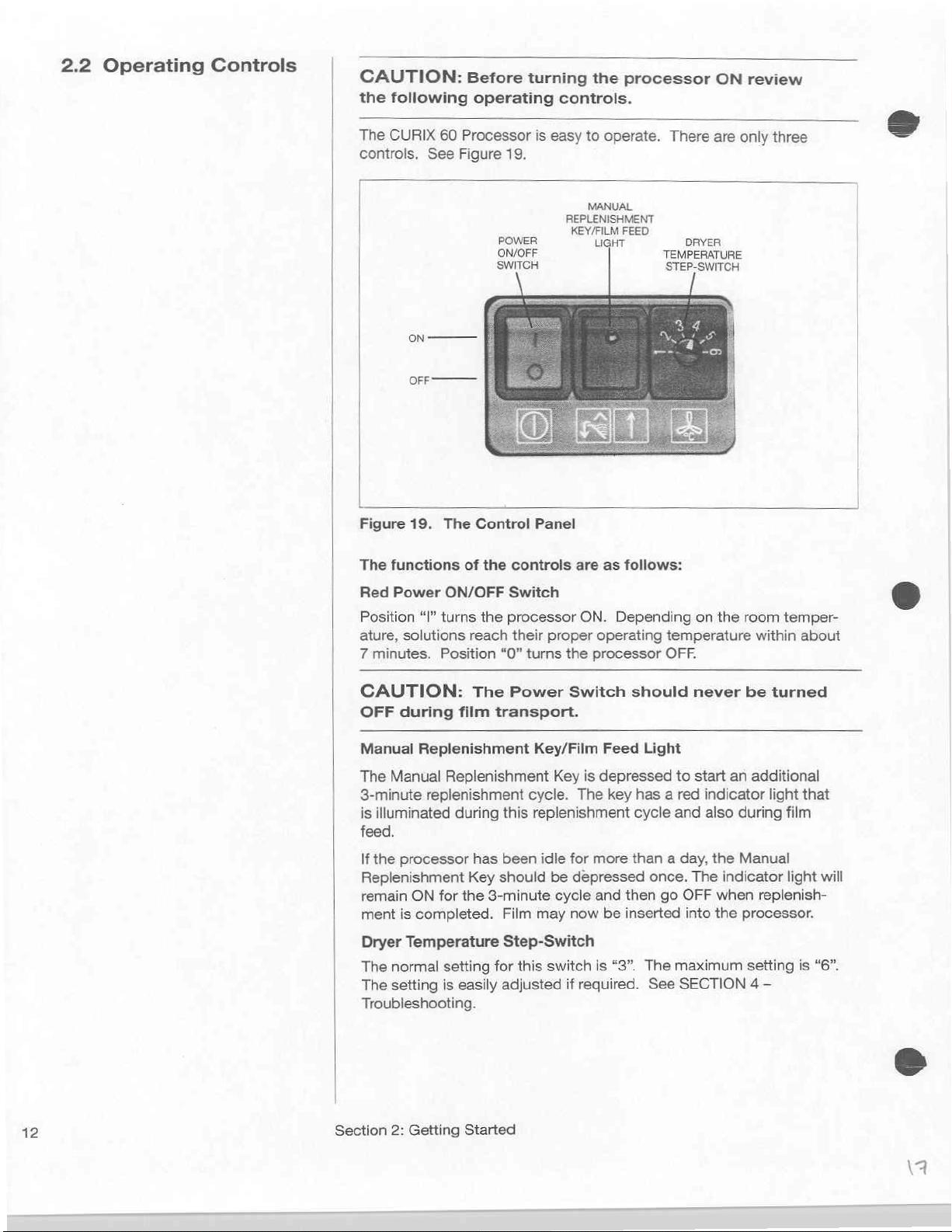
2.2
Operating
Controls
CAUTION:
the
following
The
CURIX
controls,
|
|
|
60
See
Figure
Before
operating
Processor
19.
POWER
ON/OFF
SWITCH
turning
controls.
is
easy
MANUAL
REPLENISHMENT
KEY/FILM
the
processor
to
operate.
FEED
LIGHT
ON
review
There
are
only
DRYER
TEMPERATURE
STEP-SWITCH
three
|
Figure
The
Red
Position
ature,
7
minutes.
>
OFF
19.
functions
Power
“I”
solutions
CAUTION:
OFF
during
Manual
The
3-minute
is
feed.
Replenishment
Manual
replenishment
illuminated
The
Control
of
the
controls
ON/OFF
turns
Position
film
Replenishment
during
Switch
the
processor
reach
“0”
The
Power
transport.
this
their
turns
cycle.
Panel
are
as
ON.
Depending
proper
the
processor
operating
Switch should
Key/Film
Key
replenishment
Feed
is
depressed
The
key has a red
follows:
temperature
OFF.
Light
to
cycle
and
on
the
room
never
start
be
an
indicator
also
during
temper-
within
about
turned
additional
light
that
film
If
the
processor
Replenishment
remain
ment
Dryer
The
The
Troubleshooting.
ON
is
completed.
Temperature
normal
setting
has
Key
for
the
setting
is
easily
been
idle
should
3-minute
Film
Step-Switch
for
adjusted
may
this
be
cycle
switch
for
depressed
now
if
Section
2:
Getting
Started
more
than a day,
and
then
be
inserted
is
“3”.
The
required.
once.
go
maximum
See
the
The
indicator
OFF
when
into
the
SECTION
Manual
light
replenish-
processor.
setting
4 —
is
will
“6”.
ma
Page 18

2.3
Processor
Functions
An
understanding
normal
When
are
must
are
When
Motor,
A
ratures
activated
operates
It
and
When a film
a
Replenishment
Dryer Fan
the
When
no
and
abnormal
the
Dispenser
automatically
be
level
covered
starting
takes
Fixer
pair
length
longer
The
another
on
the
Power
Tank
Heaters
cycle
and
levels.
for
for
265
about 7 minutes
solutions.
is
of
magnetic
are
of
the
end
turning,
indicator
film
to
225
the
of
the
processor
operation.
Bottles
filled to
prevent
Page 8 in
ON/OFF
is
carried
seconds
seconds
fed
into
Key
immediately
film
of
the
the
light
can
the
premature
SECTION
Switch
and
Dryer
out
During
for
The
Tank
the
rollers.
is
illuminated
to
determine
film
is
following
stays
be
fed
functions
are
inserted
bottom edge
drainage.
1.)
is
turned
Fans
start
that
is
independent
this
cycle
the
(about 3 3/4
(about 4 1/2
the
Tank
Heaters
Heaters
processor
The
activated.
detected
on
into
it
indicator
and
The
replenishment
and
occurs:
for
15
seconds.
the
processor.
will
into
the
of
the
(Instructions
ON,
to
operate.
Infrared
minutes)
minutes.)
to
are
factory
is
detected
light
on
the
Infrared
Film
the
Film
help
you
processor,
bottle
the
Drive
of
solution
Dryer
and
the
warm
the
set
at
by
the
the
Manual
Dryer
Scanner
rate.
Scanner
When
it
to
recognize
the
valves.
for
Motor,
tempe-
Heaters
Dryer
Developer
93°
F.
Film
Heaters
also
measures
rollers
goes
tanks
Tanks
leveling
Pump
are
Fan
Scanner,
and
are
off,
Provided
after
the
and
after
As
long
as
double
tents
pump
solution
their
of
the
tubes
that
last
film
an
additional
film-feed
normal speed.
Developer,
and
flow
and
wash
no
additional
exits
is
detected,
Fixer,
into
water
films
the
Dryer
40
seconds
the
This
increased
and
Wash-Water
the
drains.
is
replenished
have
been
inserted,
the
Infrared
the
Replenishment
An
automatically
Dryer
Fans
turn
circulation
Tanks
equivalent
40
Heaters
off.
Pumps
causes
to
rise
amount
from
seconds
turn
operate
the
in
their
of
fresh
the
supply.
off,
at
con-
Section
2:
Getting Started
13
\8
Page 19

2.4
Clean
Tanks
Before
Chemicals
NOTE:
Tanks
recommended
removed
and
This
the
procedure
will
After
reassembling
components,
replenishment
checked.
Prior
for
the
from
rinsed
with
will
require
standard
except
be
no
chemicals
rinsing
and
IMPORTANT:
The
Replenishment
been
factory-set
replenishment
processing
The
controlled
film
(EX:
the
width
replenishment
If
you
mainly
will
be
pumps.
Page
To
save
the
replenishment
water
Bottles.
is
satisfactory,
the
other
with
24 x 30
replenishment
by
length = 30
of
will
be
larger
necessary
See
16.
chemicals,
in
the
three
If
the
set
chemicals.
the
Adding
to
filling
the
first
time
it
is
that
they
be
the
processor
tap
water.
performing
cleaning
that
there
to
drain.
the
the
processor
rate
should
Pumps
for
average
rates
based
cm
films.
cycle
the
length
cm).
However,
the
film
will
affect
rate.
processing
or
smaller
Table 1 on
replenishment
you
of
Dispenser
to
adjust
first
rate
spare
can
either
sizes
check
using
Dispenser
then
be
have
upon
is
of
the
it
the
rate
fill
Bottles
Fr
1.
2.
3.
4.
6.
7.
8.
9.
10.
CAUTION:
Wash-Water
gears;
position;
and
replacing
is
inserted
numbered
respective
and
prd
FILL
WITH
Insert
receptacles.
proper
Lift
off
the
Receiving
Disengage
in
Figure
20.
Lift
the
Wash-Water
as
the
its
and
it
Fixer
drive
the
remove
remove
Lift
from
Remove
Lift
aside.
Remove
retaining
in
Figures
Follow
Take
and
from
replacement.
After
reversing
the
the
THE
the
the
space
24A
the
all
rinse
the
rinsing
the
the
Heater
Dryer
CHEMISTRY
WATER
Dispenser
level.
the
slots
same
the
them
Tanks
the
drain
the
into
rollers.
color-codes
TO
The
See
the
Tank
The
Wash-Water
shown
Tank
Assembly
gears.
Fixer
Tank
the
Tank
Heater,
in
the
previously
&
24B.
procedure
Tanks,
Rollers,
with
for
cleaning,
the
Tanks
disassembly
Make
Tanks
valves
Heaters
Cables
Guide
the
Check
Assembly
THE
Bottles
Tanks
Figure
Tray/Cover.
Heater
Cables
Tank
Tank
Assembly
21.
Figure
in
and
Cover
as
Guide
Plate
by
lifting
tank.
Set
the
occupied
for
Tank
luke-warm
and
and
tank
procedure.
sure
that:
are
properly
are
fastened
are
engaged
are
back
Plates,
groove
AND
2.50
are
25.
make
in
that
and
that the
Cover
WASH-WATER
LITER
into
their
automatically
from
has
slightly,
aside.
it
Set
withdraw
shown
as
shown
vertically
Heater
by
the
removal
Covers
water.
they
are
components,
the
Developer,
engaged
in
in
their
sure
the
tank
all
parts
are
MARK
color-coded
filled to
their
retaining
no
Heater
pull
it
it
enough
in
Figure
22,
in
Figure
to
disengage
(with
cable
Waste-Water
of
the
Developer
and
Guide
Rollers
may
numbered
replace
with
in
the
their
upright/closed
retaining
clips.
that
adjacent
match
Receiving/
properly
DISPENSER
the
clips as
or
Heater
forward
to
disengage
and
23,
and
attached)
Tank.
Tank.
Plates
be
removed
for
easy
them
Fixer
their
When
the
bent
to
their
Tray
closed.
BOTTLES
shown
Cable.
and
set
it
aside.
set
it
it
from
the
aside
See
to a sink
by
and
drive
slots
edge
the
even
Cover
it
Section
2:
Getting
Started
Page 20

Figure
24A.
Dise
ngage
and
Remove
Tank
Heater
Figure
23.
Remove
Guide
Plate
Section
2:
Getting
Started
Page 21
2.5
Checking
the
Current
Replenishment
Rate
2.6
Standard
Replenishment
Rate
NOTE:
ment
made
Bottles.
performed
Dispenser
initially,
required.
A
provided
some
satisfactory
Table 2 when
Adjustment
are
use
Steps 1 through 5 and 7 through
“Quick
not
the
10
will
Rate
using
time
Adjustment
The
initial
Adjustment
water
in
However,
with
Bottles
or
at
Adjustment
on
and
satisfied
Standard
apply
it
chemistry
and
some
later
Page
18.
may
results.
using
Procedure.”
with
Procedure.
in
both
Replenish-
should
be
the
Dispenser
may
also
be
in
the
Tanks,
time
as
Procedure”
It
will
save
provide
Refer
to
the
“Quick
If
you
the
results,
cases.
is
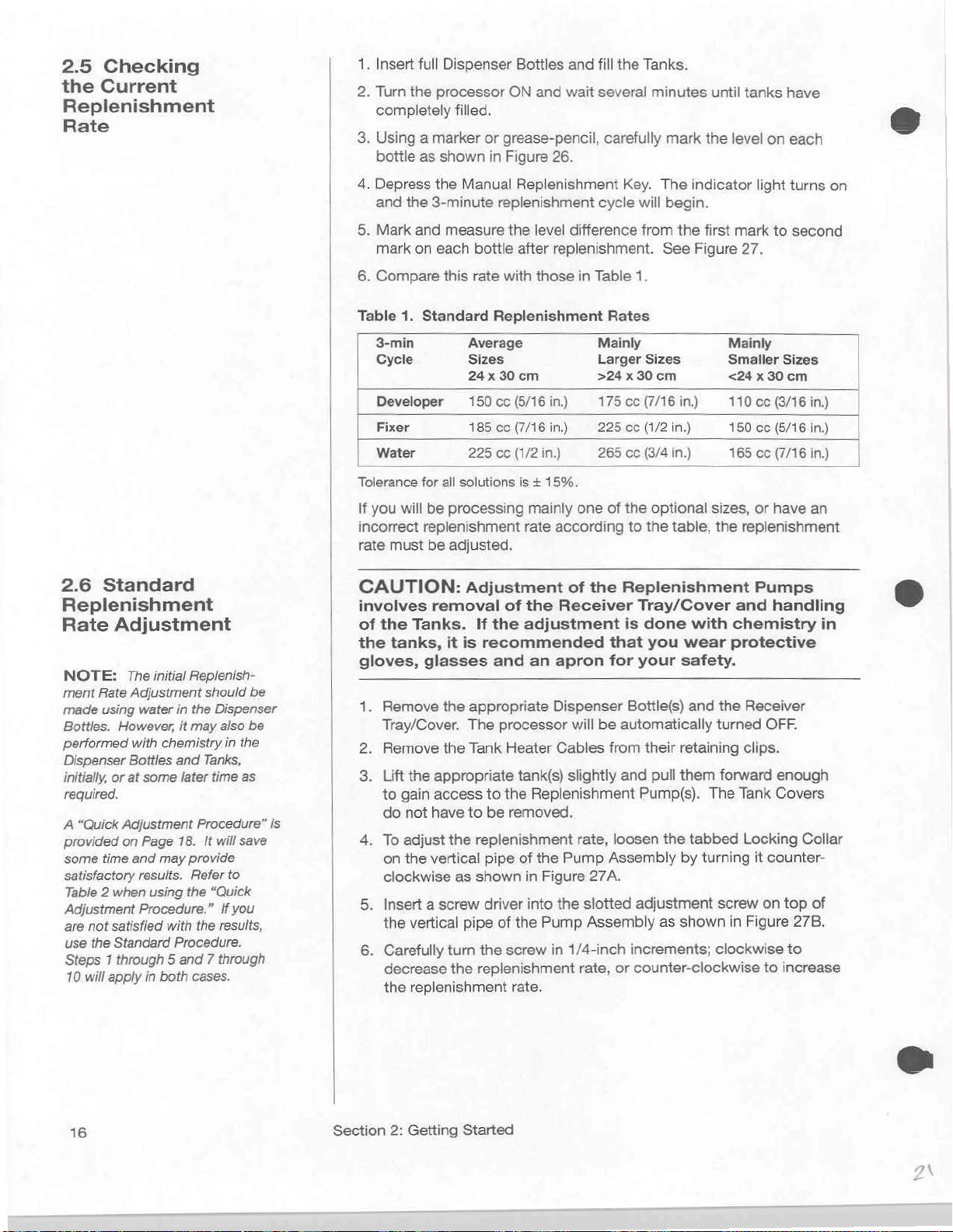
1.
Insert
full
2.
Turn
the
processor
completely
3.
Using a marker
bottle
as
4,
Depress
and
5.
Mark
mark
6.
Compare
Table
3-min
Cycle
Developer
Fixer
Water
Tolerance
If
you
incorrect
rate
the
the
3-minute
and
on
each
1.
Standard
for
will
be
replenishment
must
be
CAUTION:
involves
of
the
the
gloves,
1.
Remove
Tray/Cover.
2.
Remove
3.
Lift
to
do
4.
To
on
clockwise
5.
Insert a screw
the
6.
Carefully
decrease
the
removal
Tanks.
tanks,
glasses
the
appropriate
gain
access
not
have
adjust
the
vertical
vertical
replenishment
Dispenser
filled,
or
shown
all
in
Manual
replenishment
measure
bottle
this
rate
Replenishment
Average
Sizes
24 x 30
150
cc
185
cc
225
cc
solutions
processing
adjusted,
Adjustment
If
the
it
is
recommended
and
the
appropriate
The
processor
the
Tank
to
to
be
the
replenishment
pipe
as
shown
driver
pipe
of
turn
the
the
replenishment
Bottles
ON
grease-pencil,
Figure
Replenishment
the
after
with
cm
(5/16
(7/16
(1/2
is + 15%.
of
Heater
tank(s)
the
removed.
of
the
screw
rate.
and
fill
and
wait
several
26.
cycle
level
difference
replenishment.
those
in
Table
Mainly
Larger
>24 x 30
in.)
in.)
in.)
mainly
rate
the
adjustment
an
Replenishment
the
in
Figure
into
Pump
in
175
225
265
one
according
of
the
Receiver
apron
Dispenser
will
be
Cables
slightly
rate,
Pump
27A.
the
slotted
Assembly
1/4-inch
rate,
carefully
the
Tanks.
minutes
mark
Key.
The
indicator
will
begin.
from
the
See
Figure
1.
Rates
Sizes
cm
ce
(7/16
in.)
cc
(1/2
in.)
cc
(3/4
in.)
of
the
optional
to
the
table,
Replenishment
Tray/Cover
is
done
with
that
you
wear
for
your
safety.
Bottle(s)
automatically
from
and
Pump(s).
loosen
Assembly
adjustment
increments;
or
counter-clockwise
their
pull
the
as
and
retaining
them
tabbed
by
shown
until
tanks
the
level
first
mark
27.
Mainly
Smaller
<24 x 30
110
150
165
sizes,
the
replenishment
and
chemistry
protective
the
Receiver
turned
clips.
forward
The
Tank
Locking
turning
screw
in
Figure
clockwise
have
on
each
light
turns
to
second
Sizes
cm
cc
(8/16
cc
(5/16
cc
(7/16
or
have
Pumps
handling
OFF.
enough
Covers
it
counter-
on
top
27B.
to
to
increase
on
in.)
in.)
in.)
an
in
Collar
of
16
|
Section
2:
Getting
Started
Page 22
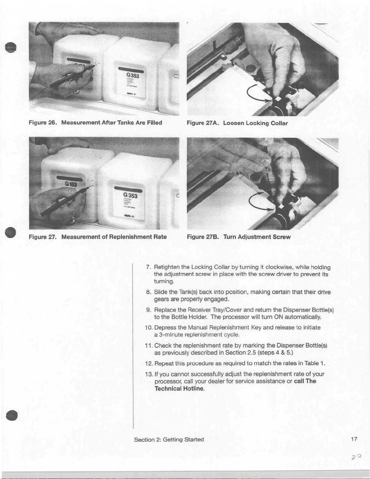
Figure
26.
Measurement
After
Tanks
Are
Filled
ῶ
Figure
27.
Measurement
of
Replenishment
Rate
7.
Retighten
the
turning.
8.
Slide
gears
9.
Replace
to
the
10.
Depress
a
3-minute
11.
Check
as
previously
12.
Repeat
13.
If
you
processor,
Technical
Figure
the
adjustment
the
Tank(s)
are
properly
the
Receiver
Bottle
Holder.
the
Manual
replenishment
the
replenishment
this
procedure
cannot
call
Hotline.
27B. Turn
Locking
screw
described
successfully
your
Collar
in
place
back
into
engaged.
Tray/Cover
The
processor
Replenishment
cycle.
rate
in
as
required
dealer
Adjustment
by
turning
with
position,
and
by
marking
Section
adjust
for
2.5
to
the
service
Screw
it
clockwise,
the
screw
driver
making
will
Key and
match
replenishment
certain
return
the
turn
ON
release
the
Dispenser
(steps 4 &
the rates
assistance
while
holding
to
prevent
that
their
drive
Dispenser
automatically.
5.)
rate
or
to
initiate
Bottie(s)
in
Table
of
call
The
Bottle(s)
your
its
1.
Section
2:
Getting Started
17
Page 23
2.7
“Quick
Replenishment
Rate
Procedure”
Adjustment
Adjustment
|
|.
Va
[>
ADJUSTMENT
SCREW
OPENING
OUTLET
PLUNGER
Screw
Detail
1.
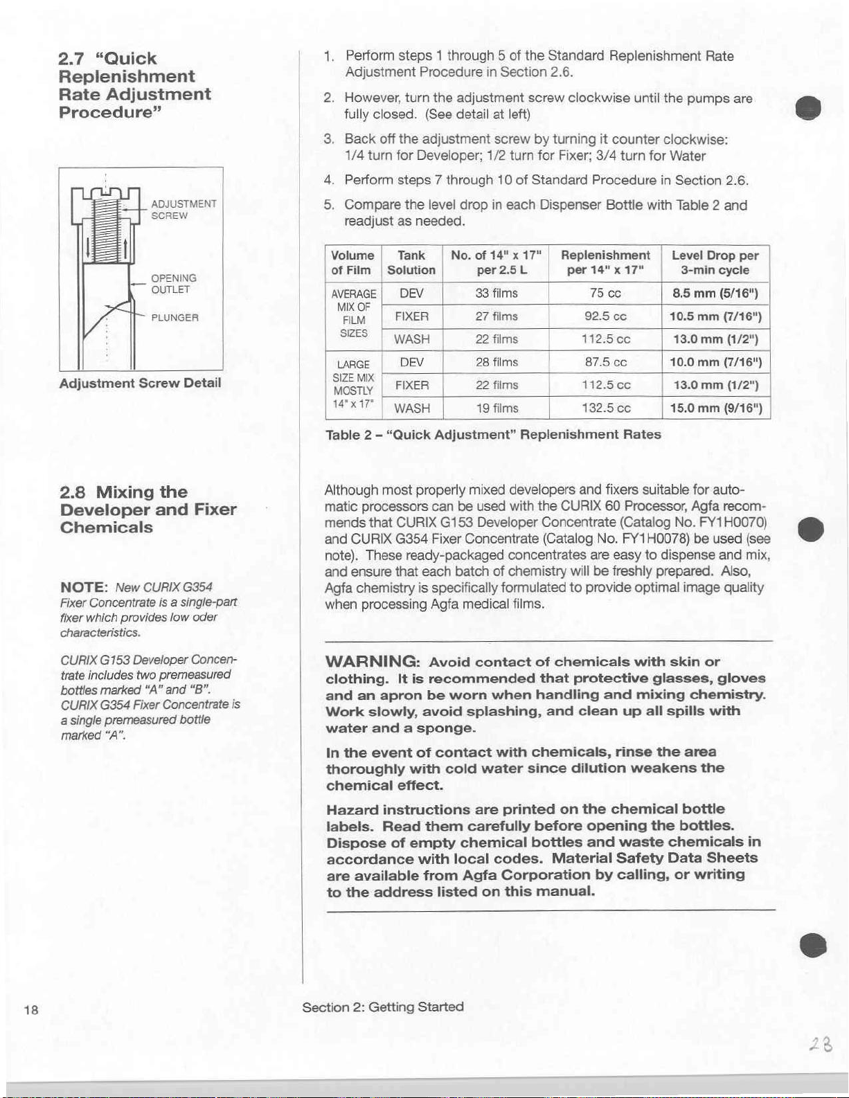
Perform
Adjustment
2.
However,
fully
3.
Back
1/4
4.
Perform
|
5.
Compare
readjust
[Volume | Tank | No.
|
of
Film | Solution
AVERAGE | DEV
MIX
OF
FILM | FIXER
|
SZES | WASH
|
LARGE | DEV
|
SIZE
MIX
Masný. | FIXER
|
Xİ”
Table 2 -
steps 1 through 5 of
Procedure
turn
the
closed.
off
turn
|
|
(See
the
adjustment
for
Developer;
steps 7 through
the
level
as
needed.
WASH
“Quick
Adjustment”
in
Section
adjustment
detail
at
left)
screw
1/2
turn
10
of
drop
in
each
of
14"x
per
2.5L
33
films
27
films
22 films
28 films
22 films
19
films
Replenishment
the
Standard
2.6.
screw
by
turning
for
Fixer;
Standard
Dispenser
17" | Replenishment | Level
per
Replenishment
clockwise
it
counter
3/4
turn
Procedure
Bottle
14" x 17"
75 00
92.5
сс
112.5
cc
87.5
сс
1
12.5
cc
132.5
co
Rates
until
the
clockwise:
for
in
with
Rate
pumps
Water
Section
Table 2 and
Drop
3-min
8.5
mm
10.5
mm
13.0
mm
10.0
mm
13.0
mm
15.0
mm
are
2.6.
per
cycle
(5/16")
(7/16")
(1/2")
(7/16")
n
(1/2")
(9/16")
|
2.8
Mixing
Developer
Chemicals
NOTE:
Fixer
fixer
characteristics.
CURIX
trate
bottles
CURIX
a
single
marked
New
CURIX
Concentrate
which
provides
G153
Developer
includes
two
marked
G354
“A”
Fixer
premeasured
“A”.
the
and
Fixer
G354
is a single-part
low
oder
Concen-
premeasured
and
“B".
Concentrate
bottle
is
Although
matic
mends
and
note).
and
Agfa
when
most
processors
that
CURIX
ensure
G354
These
that
chemistry
processing
WARNING:
clothing.
and
an
apron
Work
water
In
thoroughly
chemical
Hazard
labels.
Dispose
accordance
are
to
slowly,
and a sponge.
the
event
instructions
Read
of
available
the
address
properly
can
be
CURIX
G153
Fixer
Concentrate
ready-packaged
each
batch
is
specifically
Agfa
medical
Avoid
It
is
recommended
be
worn
avoid
of
with
effect.
them
empty
with
from
splashing,
contact
cold
carefully
chemical
local
Agfa
listed
mixed
developers
used
with
Developer
concentrates
of
chemistry
formulated
films.
contact
when
with
water
are
printed
codes.
Corporation
on
this
and
the
CURIX
Concentrate
(Catalog
will
to
provide
of
chemicals
that
protective
handling
and
clean
chemicals,
since
dilution
on
before
bottles
Material
manual.
the
opening
and
fixers
suitable
60
Processor,
(Catalog
No.
FY1H0078)
are
easy
to
be
freshly
optimal
with
and
mixing
up
all
rinse
weakens
chemical
the
waste
Safety
by calling,
for
Agfa
No.
FY1H0070)
be
dispense
prepared.
image
skin
or
glasses,
chemistry.
spills
the
area
the
bottle
bottles.
chemicals
Data
or
writing
auto-
recom-
used
and
Also,
quality
gloves
with
Sheets
(see
mix,
in
18
Section
2:
Getting
Started
Page 24

Figure
29.
Fill
G153
Dispenser
Bottle
with
Water
Figure
1.
Remove
processor.
bottles
from
the
bottle,
the
2.
Rinse
water
pour
Dispenser
slowly
3.
Pierce
and
Fill
replace
mix
4.
Follow
off
5.
Fill
mark
31.
of
the
cap
of
turn
bottle
the
to
G153
to
the seal
pour
the
bottle
the
the
solution.
the
with
water,
the
Water
and
the
G153
the
Pour
in
G153
three
empty
Take
the
concentrate
Developer
the
G153
the
cap
over
as
shown
G153
Dispenser
1.25 L mark
Developer
Bottle
as
shown
mix
the
solution.
of
G153
it
into
the
Dispenser
with
water
valve.
same
replace
Shake
procedure
if
necessary
Dispenser
the
Concentrate
Dispenser
Dispenser
to a sink.
Dispenser
Developer
and
cut
in
Figure
Bottle
as
shown
Concentrate
in
Developer
to
FULL
the
for
to
Bottle
valve.
“B”
Bottles
Bottles
Remove
Bottle.
Concentrate
through
28.
and
then
in
Figure
“A”
Figure
30.
Concentrate
Bottle.
bottle
reach
to
(2.5
to
mixing
the
the
See
L)
thoroughly
FULL
from
and
the
three
the
valve
Unscrew
“A”
the
seal
fill
it
with
29.
into
the
Agitate
Figure
mark
and
Fixer,
topping
2.5 L mark.
(2.5
the
of
Then,
“B”
31.
L)
Figure
30.
Pour
In
G153
Concentrate
“A”
Section
Getting
2:
6.
Clean
Started
up
the
work
area
with a wet
sponge.
19
Page 25
2.9
Start-up
NOTE:
will
automatically
OFF
if
the
Cover
or
Receiving
are
not
properly
NOTE:
operating
SECTION
or
call
the
But,
first
try
processor
This
can
often
problem.
The
processor
be
Dryer
Assembly
Tray/Cover
closed.
/f
you
detect
problem,
4 -
Technical
OFF
refer
Troubleshooting,
Hotline.
switching
and
ON
correct
Procedure
switched
an
to
the
again.
the
1.
Plug
the
Turn
off
2 8 Turn
the
>
Wait 7 minutes
5.
Run a test
exposed
Replenishment
the
next
6.
Check
seems
to
power
all
Processor
film
satisfactory
cord
lights
to
film
first.
film into
Switch
can
see
if
processing
but
achieve
the
be
into
the
the
darkroom
ON.
operating
Open
Feed
Slot
lights
inserted.
and
you can
start
wall
outlet.
the
Light-tight
until
(red).
drying
regular
safelight.
temperature.
Cover
the
indicator
When
the
indicator
is
satisfactory.
processing.
and
lamp
Insert
the
on
the
light
turns
If
everything
off,
20
Section
2:
Getting
Started
Page 26

SECTION
Cleaning
CURIX
3
the
60
Processor
The
following
EACH
At
the
end
prevent
should
DAY:
of
each
day’s
condensation
be
performed
work,
of
chemicals.
raise
on a regular
the
Receiving
basis:
Tray/Cover
slightly
to
NOTE:
processor
optimal
the
designed
tenance.
have
parts
easy
image
CURIX
been used
that
to
remove
Proper
cleaning
is
essential
60
Processor
for
easy
Non-corrosive
require
to
quality.
However,
cleaning
throughout,
regular
without
of
your
maintain
has
been
and
main-
materials
and
cleaning
tools.
all
are
EACH WEEK:
w
Drain
and
If
you
are
processing
following
v
ど
Tanks
If
you
perform
EACH
Vv
every
Drain
Developer
Replace
Clean
Tank
and
Film
Scanner,
are
processing
the
MONTH:
Clean
the
exhausted
CAUTION:
chemicals
apron
for
disposal
When
ing
to
your
safety
cleaning
general
protect
of
clean
Wash-Water
less
week:
and
Fixer
chemicals.
Covers
Replenishing
above
Distribution
You
with
waste
directions:
and
Feed
every
are
care,
your
and
chemistry.
the
and
more
Roller
reminded
conform
processor
Tank
than
80
Tanks
Rollers,
Pumps,
Tray.
than
80
two
weeks:
Assembly
to
wear
clothing,
films
per
and
Dispenser
Transport
Dispenser
films
per
(Squeegee
again
protective
to
wear
to
local
always
week
Bottles.
Rollers,
Bottles
week
to
handle
gloves,
protective
codes
adhere
perform
Guide
Plates,
and
Bottle
Rollers.)
all
and
glasses
regarding
to
the
the
Valves,
an
the
follow-
.
DISCONNECT
2.
Never
3.
Electric
use
hot
cables
POWER
water.
to
heaters
CORD
The
highest
are
disconnected.
4.
Never
clean
Wipe
5.
Roller
Developer
Fixer
Wash-Water
6.
The
tanks
for
ease
proper
chassis
with a damp
sets
are
Roller
Roller
sets
Roller
Tank
Covers,
are
color
of
assembly
location
or
cloth
numbered
sets
are
are
numbered
sets
Bottle
coded
after
after
cleaning.
plastic
or
sponge.
for
numbered
are
numbered
Valves,
to
prevent
cleaning.
FROM
temperature
permanent
parts
of
proper
replacement
“1” & “2”
“3” & “4”
Bottle
contamination
They
OUTLET.
and
heaters
“5” & “6”
Holder
must
allowed
must
not
in
running
after
and
chemical
of
the
be
returned
is
104°F
be
water.
cleaning.
and
chemicals
to
their
(40°C).
water
and
Section
Cleaning
3:
the
CURIX
Processor
60
21
19
S
Page 27

3.1
Removing
Cleaning
of
the
and
Tanks
-
Turn
the
=
|
.
Remove
ND
.
Remove
BO
.
Disengage
See
5.
Lift
|
|
|
gears,
6.
Remove
7.
Remove
Power
the
the
Figure
up
and
and
power
Dispenser
the
32.
forward
to
gain
the
Tank
the
Guide
Switch
cord from
Tank
to
access
Cover.
Plate.
OFF.
Bottles
Heater
Cables
disengage
to
See
See
the
and
the
the
Tank
Figure
Figure
wall
receptacle.
Receiving
from
their
Wash-Water
Drain
34.
35.
Tray/Cover.
retaining
Tank
Valves.
See
clips.
from
its
Figures
O
drive
33.
22
Section
Cleaning
3:
Figure
CURIX
the
35.
Remove
Processor
60
Guide
Plate
Page 28

.
Drain
Figure
Drain
Tube
.
Take
.
Repeat
Fixer
Чи
Remove
slots.
12.
Place
See
13.
Take
to a sink
14.
Disengage
for
the
Tank
36.
It
Tube
to
should
the
Wash-Water
steps
Tanks.
the
See
Figure
the
Heaters
Figure
38.
the
Developer
for
the
cleaning.
by
releasing
may
be
necessary
facilitate
not
be
kinked.
Tank
shown
Tank
in
Heaters
37.
in
the
and
cleaning.
Film
Scanner.
the
proper
to a sink
Figures
by
disengaging
space
Fixer
Tanks,
See
Drain
Valve
to
gently
draining.
for
33
through
vacated
Tank
Figure
Clamp
pull
on
the
For
easy
flow
cleaning.
36
for
them
from
by
the
Wash-Water
Covers
39.
Take
as
shown
end
of
the
Drain
Developer
their
retaining
and
Guide
it
to a sink
in
the
and
Tank.
Plates
Figure
Figure
36.
Drain
37.
Disengage
the
Tank
Heater
Section
3:
Cleaning
Figure
Figure
the
CURIX
38.
39.
Set
Heater
Disengage
60
Processor
in
Vacated
Film
Tank
Scanner
Space
23
N
=
Page 29

|
Perform
1.
2.
3.
4.
5.
6.
7.
8.
9.
10.
Chemistry
the
the
Remove
sponge
Unfasten
Remove
Replenishment
Observe
(black),
With
the
water,
close
the
Wash
the
If
Squeegee
washed,
Wash
and
Squeegee
Remove
Using a sponge
Clean
Clean
Clean
surface
Replace
Replace
install
codes
Replace
Cover
Tanks
following
the
Transport
and
running
the
Replenishment
and
wash
Pumps
the
Pump
to
avoid
Tank
Drain
allowing
the
the
any
of
the
carefully.
and
and
will
water
Tank
Drain
Guide
Rollers
lift
them
replace
Rollers.
the
Light-tight
Feed
Drainage
chemical
the
processor
the
Light-tight
the
Rollers,
Tank
Assemblies
the
Film
Receiver
Water
be
automatically
steps
at
the
Rollers
water.
the
color-codes,
contamination.
Valve
Plates,
(Distribution
from
them
and
Slot
and
Troughs.
residue
Scanner
Tray/Cover.
Dispenser
See
Pumps
Pumps.
and
refasten
open,
to
drain
Valve.
Tank
Covers
their
support
as
one
Cover
luke-warm
Tray.
on
chassis.
Cover
Guide
Plates,
into
and
sink:
from
the
Tanks
Figure
40.
by
See Figures
them
Developer
wash
each
through
Accessory.
See
See
Accessory.
securely
refilled.
and
Roller
blocks
unit.
Do
water:
Figure
Figure
the
Bottle
Heaters,
the
processor,
Bottles
the
Assembly)
and
rotating
41 & 42.
with
the
(red),
Tank
valve.
Rollers.
as
shown
not
disassemble
44.
45.
Holder
and
close
the
may
now
wash
the
retaining
retaining
Fixer
under
After
have
in
and any
Tank
Follow
Dryer
be
inserted
them
with
levers.
Replace
levers.
(white),
running
draining,
to
be
Figure
the
exterior
Covers
the
and
color-
Assembly
a
the
Water
43.
and
Section
3:
Cleaning
the
CURIX
60
Processor
Page 30

Figure
44.
Figure
42.
Remove
and
Replenishment
Wash
Section
Pump
3:
Cleaning
_—‘
Figure
the
CURIX
45.
Clean
60
Processor
Drainage
Troughs
25
Page 31

SECTION
4
Troubleshooting
Checklist
NOTE:
be
the
then,
Some
Parts
Instructions
SECTION
The
the
parts.
can
screwdriver,
are
4.1
Fails
Power
some
corrected
Power
Service
most
be
not
Switch
ON
again.
problems
replacement
5 —
common
Most
replaced
required.
Processor
to
Operate
Switch
problems
simply
OFF,
may
and
are
provided
Maintenance.
Parts
Kit
replaceable
of
these
with
and
special
may
by
turning
and
require
in
contains
parts
only
a
tools
—
is
ON
—
|
The
Nevertheless,
improper
malfunction,
determine
a
service
ο
Most
operating,
the
setup,
the
problem
The
following
correct
require
Need
you
Call
required,
dealer
Check
a
M
Check
Check
αι
CURIX
60
operating
its
technician.
problems
replenishment
operating
may
the
most
assistance,
It.”
It
will
our
Toll-Free
you
from
which
that
the
that
Processor
if
you
this
section
cause,
related
be
Troubleshooting
common
tell
you
can
arrange
your
the
Power
condition
the
Receiver
is
designed
encounter
procedures,
is
provided
and
find
to
processed
or
cleaning
and
cleaning
caused
check
Technical
by
problems.
Appendix
what
for
processor
Cord
of
the
Tray/Cover
information
one
for
some
Problems
Processing
to
out
if
it
can
film
procedures.
instructions
an
electrical
Checklist
If
C
for
Hot-Line.
at
this
was
purchased.
is
plugged
fuse
to
the
trouble-free
which
techniques,
help
you
analyze
be
remedied
can
be
traced
in
SECTIONS
or
mechanical
should
you
you
time,
is
encounter
“How
should
If
a
service
or
in.
power
firmly
in
help
to
by
outlet.
Operation.
result
without
to
If
you
you
difficulty
Get
Help
have
technician
calling
place.
from
or
equipment
the
problem,
requiring
improper
have
followed
1,
2,
and
malfunction.
to
identify
When
ready
the
and
and
You
before
is
local
3,
απ
Check
and
Receiver
Pin
is
Q
Check
Replace
Procedure
If
none
Power
Hotline
that
the
missing
the
fuse
the
fuse
5.1.2,
of
the
Switch
for
Service
Interlock
Tray/Cover
it
must
be
SI-2
(6.25
if
it
is
blown.
Page
34.
above,
the
or
electrical
Assistance.
Pins
are
present
are
engaging
replaced.
A)
in
the
See
problem
circuit
may
malfunction.
in
the
the
Interlock
compartment
SECTION
be
caused
Dryer
Assembly
Switch.
under
5
—
Maintenance,
by
a
defective
Call
The
Cover
If
either
the
Dryer.
Technical
26
Section
4:
Troubleshooting
Page 32

4.2
Film
Transport
Failure — Power
is
ON
Figure
the
46.
Depressing
Interlock
Switch
Switch
O]
Check
must
the
Receiver
OFF.
Switch
To
momentarily
Switch
shown
CAUTION:
glasses
also
recommended
handling
O
If
a
film
(ie:
Developer,
Remove
Check
Transport
jammed
Section
replacement.
that
all
the
rollers
be
ON.
However,
Tray/Cover
It
is
necessary,
to
turn
the
processor
check
through
in
Figure
the
46.
Dryer
Always
and
an
apron
that
parts
submerged
is
jammed,
the
for
mechanical
Rollers
film,
5 — Maintenance,
or
Fixer,
Receiver
or
adjust
Guide
component(s)
are
turning.
to
view
and
this
therefore,
ON.
the
transport
Assembly
wear
rubber
when
the
in
fails
to
transport
or
Wash
Water)
Tray/
Cover
problems
Plates,
Procedure
To
do
the
rollers,
automatically
to
manually
rollers,
Cover
gloves,
exposed
Tanks
chemistry.
and
such
or
and
to
be
through
turn
the
appropriate
as
displaced
defective
resume
Page
5.2,
this
the
it
is
necessary
turns
actuate
depress
with
a
pen
protective
chemicals.
drained
a
particular
Power
gears.
operation.
36
Power
the
the
the
or
before
Switch
Tank
Roller
Withdraw
for
gear
Switch
to
remove
processor
Interlock
Interlock
pencil,
Cover(s).
as
It
is
section,
OFF.
Racks,
See
O
Ifa
film
caused
chemistry.
To
resume
Receiver
processor
ΠΠ
If
no
rollers
Call
The Technical
O
If
individual
POWER
the
Tank
Rollers
SECTION 5 —
The
trouble
snap
rings
to
gain
Maintenance,
is
wrapped
by
exhausted
processing,
Tray/Cover,
to
recycle.
SWITCH
Cover(s).
and
access
and
are
turning,
rollers
Drive
Gears.
Maintenance,
may
also
in
the
Main
to
the
Procedure
around a Transport
chemicals.
replace
Hotline.
are
OFF.
Then,
turn
the
the
not
turning,
Inspect
remove
Defective
be
caused
Drive
Main
Drive
5.3,
the
Tank
Power
Drive
Motor
check
the
the
Procedure
by
System.
System.
Page
Roller,
Remove
Cover(s),
Switch
may
their
Upper
Roller
gears
must
5.2.
loose
or
The
rear
See
40.
the
problem
the
film
firmly
ON.
Wait
be
defective.
drive
Rollers
and
pairs
to
be
replaced.
missing
cover
SECTION 5 —
and
replace
close
for
gears.
Drive
inspect
gears
must
is
probably
the
the
the
TURN
Gears
the
Drive
See
and/or
be
removed
THE
in
Section
4:
Troubleshooting
27
Page 33

4.3
Film
Problems
Drying
Most
film
the
the
temperature
|
more
film
drying
due
to
problem
Control
ofthe
problems
inadequate
can
also
Circuits,
or
following:
Dryer
humidity
are
caused
Fixer
replenishment
be
caused
or
replenishment
conditions..
by
by
mechanical
You
insufficient
or
exhausted
system,
may
or
electrical
have
to
hardening
or
Fixer.
by
adverse
check
of
the
However,
failure
one
or
in
4.3.1
(Dryer
O
O
(I
MECHANICAL/ELECTRICAL
Infrared
Check
should
than
Check
OFF,
sequence.
a
Assembly.
call
the
Assembly
the
for
be
80%.
that
and
blown
Check
CM+7.0451.9705.0)
Maintenance,
If it
If
Check
Interlock
pencil
If
not
the
blows a second
fuse
SI-1
The
that
Dryer Fan
Dryer
to
fuse
SI-1
light,
Tubes
excess
less
than
the
Dryer
then
ON
If
the
Dryer
fuse
SI-1.
6.25A-fuse
If
fuse
Procedure
is
O.K.but
Technical
the
Infrared
cycle.
Cover.
Assembly
Switch
keep
they
will
processor
is
not
are
and/or
temperature
86° F and
Fans
are
to
activate
SI-1
SI-1
from
time,
the
Hotline.
They
However,
Cover
have
blown
probably
Fans
are
which
is
blown,
Service
5.1.2,
call
Dryer
Tubes
can
in
and
to
manually
turned
and
either
defective.
a 4
Dryer
or
humidity.
relative
operating.
1/2-minute
inoperative,
replace
Page
The
Fans
in
the
be
order
Receiver
ON.
Fans)
humidity
is
located
it
Parts
Kit.
34.
Technical
are
Dryer
viewed
to
light
Tray/Cover
depressed
or
both
Call
Ambient
should
Turn
the
(265
second)
the
problem
under
the
with a fuse
See
SECTION 5 —
Hotline.
still
not
operating,
Assembly
by
removing
the
Infrared
using a pen
of
the
Infrared
The
Technical
temperature
be
less
Power
Switch
fan
may
Dryer
(Part
No.
light
during
the
Dryer
Tubes
removed,
Tubes
Hotline.
be
with
the
or
do
28
If
fuse
SI-1
is
not
blown
and
both
are
not
Board.
Page
functioning,
See
SECTION 5 —
34.
check
SI-3
Maintenance,
Section
4:
Troubleshooting
or
the
the
Dryer
Fans
1.6A
fuse
Procedures
and
Infrared
on the
Timer
5.1.1 & 5.1.4,
Tubes
Circuit
Page 34

4.3.2
(Fixer
C1
If
the
have
and
The
cycle
times
O
Ifthe
O
If
the
speed,
Motor,
CHEMICAL/REPLENISHMENT
and
Fixer
Replenishment)
processor
to
be
wait
for
indicator
and
its
normal
Indicator
Indicator
the
or
has
been
replenished.
the
3-minute
light
should
the
Replenishment
speed.
does
not
does
light
problem
an
electrical
may
idle
for
Depress
replenishment
remain
Pump
light,
See
but
the
Pump
be a blown
problem.
See
more
the
illuminated
than
Manual
cycle
Motor
should
Procedure
Motor does
fuse
SI-2, a defective
Procedure
one
day,
the
Fixer
Replenishment
to
be
completed.
for
the
full
3-minute
operate
4.3.3.
not
increase
4.3.3.
Key
at
two
Pump
may
in
A Since
О
O
4.3.3
the
problem
replenishment,
the
Dispenser
Key
and
following
replenishment
replenishment
and
2.7.
ifthe
replenishment
running
If
If
on
Dispenser
Fixer
will
test
an
exposed
there
is
still a drying
the
tanks
have
Page
21,
Bottle.
in
the
Dispenser
fill
automatically.
sheet
of
could
the
replenishment
Bottle
prior
steps 2 through 6 on
rate
is
incorrect
rate
adjustment
rate
test
problem,
not
been
SECTION
film.
3,
Replace
Bottle
Check
MECHANICAL/REPLENISHMENT
(Replenishment Pump,
O
Listen
for
the
motor
speed
the
Manual
defective
fuse
Instructions
Maintenance,
Pump
Call
Replenishment
or
fuse
SI-1
in
the
for
Motor
The
Technical
sound
does
replacement
of
not
increase
SI-2
could
compartment
replacing
Procedure
Hotline.
also
be
caused
rate
to
depressing
according
steps
on
is
correct,
sheet
cleaned
drain
the
Gears,
the
Replenishment
Key
this
5.1.3,
requires a Service
check
of
film.
the
Fixer
according
and
clean
Fixer
Tank.
and
insert
for
proper
Motor,
to
two times
is
depressed,
be
blown.
underneath
fuse
are
Page
34.
by
insufficient
can
be
checked
the
Manual
Page
16,
to
Table
Page
16 - 18,
for
proper
may
be
to
the
Fixer
Mix a new
Dispenser
drying
by
Drive
Pump
its
the
Fuse
SI-2
the
Dryer
provided
Technician.
Fixer
by
Replenishment
SECTION
1,
perform
SECTION
film
drying
exhausted.
the
weekly
Tank
and
solution
Bottle.
running
an
Belts)
Motor.
normal
motor
in
If
rate
could
is
located
Assembly.
SECTION
marking
2.5.
the
schedule
of
The
Tank
exposed
the
when
be
next
5 —
If
the
2.5
by
to
O
If
the
Pump
Motor
seems
to
be
Fixer
Replenishment
be
caused
Belt
pass
Replenishment
or
Pump
through
by a defective
Motor
the
Drain
Key
Pump
is
Pump
Drive
Belt.
Hoses
is
depressed.
Section
4:
Troubleshooting
operating
operating
Gear,
Pump
Check
into
the
to
Waste
properly,
properly.
Drive
see
whether
Bottles
check
The
trouble
Gear,
chemicals
when
that
Pump
the
the
may
Drive
29
Page 35

|
1
1
|
SPACERS
|
Figure
47.
Bevel
Gears
A
É
Cheek
if
any
gears
To
inspect
Tray/Cover
procedure.
processor
The
Drive
or
both
The
may
of
the
spare
Service
is
defective,
If
none
O.K.,
belt
Drive. A spare
Service
Maintenance,
The
This
at
the
provided
defective,
the
and
Manually
as
shown
Pump
Gears
Gear.
Both
gears
are
height
of
the
require
connects
trouble
belt
adjustment.
Pump
Gears
Pump
Gear
Parts
Kit. A spare
call
of
the
Pump
check
for a broken
Parts
Kit.
may
simultaneously
same
time
in
your
call
are
binding
Pump
Gears
and
Tank
Cover needs
depress
in
Figure
must
be
properly
gears
are
beveled
defective
Pump
are
(Part
The
Gears
the
Pump
belt
(Part
For
Procedure
also
as
the
Service
The Technical
or
Gear
Instructions
provided
No.
CM+7.9432.2854.1)
Drive
Technical
are
or
slipping
Drive
No.
replacement
5.3.3,
be a broken
drives
Pump
Parts
or
making
Pump
to
the
Interlock
46.
worn,
is
critical
in
Gear
Hotline.
turning
Motor
CM+7.0389.6536.0)
Page
or
the
Motor
Kit.
Hotline.
any
unusual
Drive
Gears,
be
removed
Switch
engaged
as
replenishment
for
SECTION 5 —
Pump
to
instructions,
42.
slipping
three
Drive
If
the
with
shown
to
gear
adjustment
is
not
provided.
but
the
Pump
Motor
the
Replenishment
Pump
pumps.
Belt. A spare
Pump
in
engagement
Gear
noises.
the
Receiver
as
in
the
cleaning
to
restart
their
associated
Figure
47.
will
be
affected.
and
replacement
Maintenance.
is
provided
If
this
Motor
Drive
Belt.
Pump
is
provided
see
SECTION 5 —
Gear
Drive
It
may
be
is
Drive
Belt
the
If
either
and
A
in
your
part
sounds
This
in
your
Belt.
inspected
not
is
4.4
Appearance
Processed
Film
of
4.4.1
O
SCRATCHING
Check
and
口
condition
clean
them
Dry
the
Feed
Check
the
The
Receiver
removed.
CM+7.8185.6023.1)
Instructions
SECTION 5 —
O
Check
Dryer
and
for
Cover
luke-warm
of
the
with a sponge
Table
prior
Dryer
Guide
Tray/Cover
See
Figure
are
for
replacing a Guide
Maintenance,
dirt
or
deposits
is
removed.
water.
(lengthwise)
Feed
Table
and
and
luke-warm
to
processing a film.
Plates
for
loose
and
the
Dryer
48,
Several
included
on
Clean
replacement
in
the
Plate
Procedure
the
Dryer
the
Guide
the
Tank
or
missing
Cover
Service
Keeper
5.5.
Guide
Plates
Guide
Plates
water
if
required.
Keepers.
must
first
Keepers
Parts
Kit.
are
provided
Plates
while
with a sponge
be
(Part
the
No.
in
30
Section
4;
Troubleshooting
35
Page 36

に
ーー
Figure
48.
Checking
Keepers
and
Guide
Plates
4.4.2
a
ROLLER
Check
the
Receiver
access
water
Check
replace
Service
Check
Q
Figure
7.9432.2022.0
Service
Check
follow
Check
Follow
Check
Maintenance,
MARKS
condition
Tray/Cover,
the
rollers.
or
remove
the
Tank
them
with
Parts
Kit.
the
upper
49.
Replacement
through
Parts
Kit.
Developer
steps
on
Developer.
regular
the
cleaning
Squeegee
Procedure
(crosswise)
of
the
Tank
Tank
Clean
the
them
and
Roller
Springs
spares
See
and
See
replenishment
Pages
(Part
SECTION
lower
Gears
CM+
SECTION 5 —
16
Exhausted
procedure
Roller
5.2.3.
Rollers
clean
Roller
7.9432.2116.0)
-18,
Drive
and
Covers
rollers
for
Developer
and
with a sponge
them
proper
No.
CM+7.9432.2109.1)
5 —
Maintenance,
Drive
and
Fasteners
Maintenance,
rate.
If
SECTIONS
in
SECTION
Gear.
Squeegee
Dryer
in a sink.
tension.
Gears
for
(Part
are
adjustment
2.6
and
should
3.
See
SECTION 5 —
Rollers.
Assembly
and
luke-warm
If
they
from
Procedure
damage.
No.
CM+
included
Procedure
is
required,
2.7.
be
replaced.
Remove
Cover
are
See
in
the
to
loose,
your
5.4.1.
5.2.1
Figure
49.
Checking
the
Roller
Section
4:
Troubleshooting
Drive
Gears
31
Page 37

Figure
Squeegee
50.
Checking
Roller
Assembly
the
4.4.3
1
Check
warm
must
and
Rollers.
©
Check
Springs.
the
Roller
semble
loose,
are not
by
the
Procedure
WATER
the
Squeegee
water.
first
be
Wash-Water
See
the
Squeegee
The
cluster
calling
Retaining
of
Assembly
the
Squeegee
the
springs
supplied
The
5.4.2.
SPOTS
Rollers
The
Receiving
removed.
Tank
Figure
50.
Roller
Retaining
five
rollers
to
inspect
will
in
the
Technical
Springs
for
Tray/Cover
Removal
will
provide
Assembly
Springs
together
the
Rollers
have
to
Service
Hotline.
are
provided
dirt
deposits.
of
the
easier
(Part
tightly.
springs
at
this
be
replaced.
Parts
Instructions
in
Clean
and
Dryer
Water
Dispenser
access
for
stretched
No.
CM+
7.8187.6853.0)
Remove
on
each
end.
time,
however,
The
Kit
and
will
for
SECTION 5 —
with
luke
Assembly
Bottle
to
the
Squeegee
Retaining
the
Squeegee
Do
not
if
the
rollers
Retaining
have
to
be
replacement
Maintenance,
Cover
hold
disas-
are
Springs
ordered
of
Figure
Developer
51.
Checking
Temperature
4.4.4
©
Check
DD
Check
(I
Check
4.4.5
©
Check
Manual
cycle.
Run
©
Check
not
(1
The
Drain
Developer
©
Check
If
adjustment
IRREGULAR
that
the
dryer
that
the
room
for
proper
operation
INSUFFICIENT
the
Developer.
Replenishment
an
exposed
the
in
the
range
Developer
and
the
test
developer
of
92° F to
may
clean
the
in
the
Dispenser
developer
is
required,
DRYING
temperature
temperature
PATTERNS
of
the
CONTRAST
If
the
processor
Key and
sheet
temperature.
be
improperly
Developer
replenishment
follow
of
film
94°
in
the
wait
F,
Tank
the
is
not
too
is
not
too
Dryer
Fan.
has
for
the
to
check
See
Figure
call
The
mixed
or
and
Dispenser
Bottle
and
rate.
procedures
high.
low.
See
4.3.1.
been
idle,
3-minute
results.
51.
If
the
Technical
may
be
exhausted.
Bottle.
refill
the
See
Page
on
Page
on
Page
press
the
replenishment
temperature
Hotline.
Mix
new
Developer
16,
SECTION
16 -18.
28.
is
Tank.
2.5.
(
Check
on
the
Page
Replenishment
29.
System.
See
Procedures
4.3.2.
and
4.3.3
Section
4:
Troubleshooting
Page 38

4.4.6
(I
Make
EXCESSIVE
the
same
checks
CONTRAST
as
in
Procedure
4.4.5.
4.5
Excessive
Replenishment
4.4.7
©
Make
4.4.8
© The
the
in
the
O
Make
CO
Check
SECTION
Pages
O
Check
in
excessive
SECTION
INSUFFICIENT
the
same
checks
DENSE
Developer
Developer
Dispenser
the
the
16-18.
that
FOGGING
may
Tank
Bottle
same
checks
developer
2.
If
adjustment
the
processor
drainage.
1.
DENSITY
as
in
Procedure
be
contaminated
and
Dispenser
and
refill
as
in
Procedure
and
replenishment
is
required,
is
level.
See
Leveling
4.4.5.
by
Bottle.
the
Developer
4.4.5.
follow
Incorrect
Procedures
fixer.
Drain
Mix
rate.
See
procedures
leveling
new
Developer
Tank.
Page
on
and
can
Page
clean
16,
on
result
8,
Section
4:
Troubleshooting
33
W
GO
Page 39

SECTION
Maintenance
Procedures
5
CAUTION:
turned
outlet
OFF
before
Make
and
the
attempting
sure
power
that
the
Processor
cord
is
to
replace a fuse.
unplugged
Power
from
Switch
the
wall
is
5.1
Replacement
of
Fuses
5.1.1.
The
drawer
turning
Pull
the
Remove
included
the
Power
5.1.2.
Fuse
remove
the
Receiver
Rear
Assembly
Lift
Figure
Remove
Replace
sure
Cover,
Receiver
ON. The
REPLACING
1.6A
under
the
the
drawer
drawer
screw
Switch
REPLACING
SI-1
the
Rear
Transport
the
compartment
57.
that
Bottle
Fuse
(Part
the
Feed
slotted
as
the
in
your
one
is
Dispenser
Transport
Tray/Cover
straight
Fuse
it
and
the
the
Tray/Cover.
Dryer
screw
out.
shown
defective
Service
half
turn
ON
to
located
System
up
SI-1
insert
compartment
Dryer
Holder,
Fans
THE
1.6A
No.
CM+
7.0451.9608.0)
Tray.
Using a screw
in
the
drawer
See
Figure
in
Figure
fuse
Parts
clockwise.
resume
THE
in a compartment
Bottles,
System
and
Cover
as
shown
cover
(Part
the
spare
Drive
Gear
Dispenser
Plug
and
52.
53.
from
the
Kit.
operation.
6.25A
Bottle
Cover ( See
the
Dryer
(See
in
off
to
gain
No.
CM+7.0451.9705.0)
which
cover
and
is
engaged.
Bottles,
in
the
Power
Heaters
FUSE
one
The
fuse
fuse
holder
Close
the
Plug
in
FUSE
under
Holder
Figure
Assembly
Figure
Figure
56.
access
is
included
the
Dryer
Dryer
Cord
should
be
is
located
driver,
half
turn
is
located
and
drawer
the
Power
SI-1.
the
Dryer
and
the
54).
Cover.
55),
and
to
the
Roller
Replace
Assembly
and
operative.
in
the
access
release
lift
in
turn
the
latch
counter-clockwise.
at
the
left
insert a spare
and
lock
it
by
Cord
and
turn the
Assembly.
two
screws
Then
remove
Finally,
fuses,
is
your
Assembly.
the
the
Dryer
as
clearly
Service
Rear
Cover
the
Power
remove
Roller
shown
identified.
Parts
Transport
and
by
side
of
fuse,
turning
First,
securing
the
the
in
Kit.
Make
Switch
@
34
5.1.3.
If
Fuse
next
described
Switch
5.1.4.
Fuse
the
ever
however,
Technical
REPLACING
the
Replenishment/Circulation
SI-2
is
probably
to
Fuse
SI-1.
in
5.1.2.
is
turned
ON,
REPLACING
SI-3
protects
microprocessor
require
replacement.
this
may
Hotline.
THE
blown.
See
Figure
to
replace
the
motors
THE
the
low-voltage
and
control
indicate a serious
If
it
6.25A
Fuse
57.
the
400MA
is
Section
5:
Maintenance
FUSE
Motor
or
SI-2
is
Follow
blown
Fuse
should
start.
FUSE
Transformer
circuit
boards.
blown,
it
electrical
SI-2
Drive
Motor does
located
the
same
SI-2.
SI-3
and
This
can
be
problem.
in
the
compartment
procedures
When
power
fuse
should
replaced
Call
not
the
Power
source
as
in
The
operate,
as
for
seldom
5.1.2,
Page 40

Figure
54.
Unscrew
a
Rear
Transport
System
„al
Cover
=
Figure
=
57.
|
「
Remove
τες
Compartmei
i
int
Cover
Section
5:
Maintenance
Page 41

5.2.
Replacement
Defective
Gears
of
CAUTION:
parts
that
protection
the
Tank(s)
The
parts
When
are
in
should
and
may
now
maintenance
contact
then
be
be
with
worn.
rinse
safely
chemistry,
Remove
the
parts
handled
procedures
rubber
the
Dispenser
in
water
without
require
gloves
to
remove
rubber
the
handling
and
suitable
Bottle(s),
gloves.
drain
all
chemicals.
of
GENERAL
After
locating a defective
general
1,
Remove
prying
2.
Withdraw
pins
CM+6.0200.449.00)
removed.
3.
Replace
been
your
5.2.1.
Remove
Figure
Remove
Figure
Replace
Check
Roller
turns
resumed.
PROCEDURE
procedure.
the
it
off
the
which
the
damaged,
Service
REPLACING
the
Snap
58.
the
Fastener
59.
Drive
Gear.
the
assembly
smoothly,
gear,
retainer
with a screw
may
gear
Parts
gear
slowly
hold
can
and
or a Shaft
Kit.
Snap
the
Snap
A
Ring
(Part
and
by
turning
the
Tank
driver.
from
gear
fall
TANK
No.
the
Upper
removal
Ring
(Part
its
shaft,
to
the shaft.
out
of
Ring
in
Pin
is
lost,
COVER
CM+
Rack
the
Drive
Cover
and
replacement
No,
CM+
7.9402.1129.0)
so as not
Cylinder
the the
drive
reverse
replace
shaft
order.
it
with a new
DRIVE
7.9402.1129.0)
Drive
Gear
Gear
with
your
may
be
replaced
follows
to
lose
Pins
when
If a Snap
GEAR
as
shown
as
shown
finger.
and
operation
this
any
cylinder
(Part
the
Ring
one
in
in
If
Drive
by
No.
gear
has
from
is
36
NOTE:
can be
raised
shaft
by
washers
the
Gear.
Unless
required,
tion
of
the
be
changed.
be
reused
ject
to
wear.
The
the
or
lowered
adjusting
below
specifically
the
number
washers
The
as
they
Pump
Gear
the
number
the
Pump
and
should
washers
are
not
on
the
posi-
not
my
sub-
of
5.2.2
Remove
Page
Pry
Gear
Remove
Gear))
The
Gear
Replace
in
your
REPLACING
25,
off
the
onto
and
“D”
to
prevent
the
same
Service
the
Replenishment
Figure
41.
Snap
Ring
the
Pump
the
washers
the
Pump
shape
of
the
it
from
the
Pump
position)
Parts
(Part
Shaft
(there
Gear
shaft
Gear
on
Kit.
A
REPLENISHMENT
Pump
No.
CM+
as
shown
may
(Part
matches
turning
independently.
and
washers
the
shaft
—e
Re-install
the
Replenishment
Pump
Section
5:
Maintenance
following
7.9402.1129.0)
in
be
several
No.
CM+7.9432.2854.1)
the
and
into
Figure
shape
(use
the
fasten
the
the
60.
above
of
See
same
with a Snap
Tank.
PUMP
procedures
that
holds
and
below
from
the
hole
in
Figure
61.
number
Ring
GEAR
in
SECTION
the
the
the
the
of
included
3,
Pump
Pump
shaft.
Pump
washers
in
e
Page 42

a
Figure
59.
Remove
Fastener
K
and
Drive
Gear
Figure
61.
Removing
Washers
and
Pump
Gear
Section
5:
Maintenance
Page 43

NOTE:
that
the
Wash-Water
removed
access
Gear.
removal
Bottle.
Tank
procedures
Tank.
required.
to
to
This
of
Drain
according
Rubber
itis
recommended
provide
the
Squeegee
will
also
require
the
Water
the
Wash-Water
to
normal
and
remove
gloves
Tank
be
easier
Drive
the
Dispenser
the
are
not
5.2.3.
SQUEEGEE
CAUTION:
Infrared
to
continuing
-
©
Remove
remove
slightly
Cover
sink
|
REPLACING
touch them.
the
the
and
the
and
the
intothese
TRANSPORT
If
the
Dryer and
Wait
with
this
Receiver
Wash
Water
lift
it
out
exposed
dryer
areas.
drain
frame
THE
SQUEEGEE
processor
Fans
may
until
they
procedure.
Tray/Cover,
Tank.
Raise
of
the
processor
hole
and
with
tape
GEARS
has
still
have
Dryer
the
as
the
space
to
prevent
DRIVE
been
be
Assembly
shown
in
hot,
cooled
Squeegee
in
between
small
AND
operation
so be
Cove.
Figure
off
Roller
the
parts
careful
before
Drain
Assembly
62.
processor
from
the
not
and
falling
Remove
red
Figure
Check
and
See
Remove
certain
close
and
5.2.4.
DRIVE
Remove
Bottles,
|
System
|
Remove
the
Remove
Transport
Figure
Replace
System
Transport
operation.
and
Squeegee
63.
the
replace,
Figure
the
to
the
the
Water
REPLACING
the
Bottle
Cover
the
compartment
Snap
65.
the
Cover.
Dryer
Assembly
replace
Drive
Parts
are
two
Squeegee
if
necessary,
64.
tape,
engage
Drain
Valve.
Dispenser
GEAR
Receiver
Tray
as
Rear
Ring
Drive
Gear
compartment
Insert
System
Cover,
Snap
Ring
Gear
(Part
included
Transport
with
and
replace
the
Drive
Replace
Bottle.
THE
Tray/Cover,
and
the
shown
Transport
cover
(Part
(Part
and
Cover.
and
earlier
as
No.
No.
cover,
fasten
Replace
(Part
No.
No.
CM+7.8187.6655.1)
in
your
Service
Gears
spares
the
Gear.
Squeegee
Replace
the
Tank
Resume
from
DRYER
Dryer
Assembly
two
screws
in
System
shown
CM+
CM+7.9462.1218.0)
Dryer
the
Receiver
fastening
Figure
Cover,
in
Figures
7.9402.1129.0)
Assembly,
two
the
Bottle
Tray/Cover.
CM+7.9402.1129.0)
as
shown
Parts
Kit.
(Part
No.
CM+7.8187.6863)
your
Roller
the
Wash-Water
Cover,
normal
Service
Receiver
operation.
Parts
Assembly,
Tray/Cover
TRANSPORT
54.
the
55,
screws
Tray,
Cover,
the
Dryer
56 & 57.
and
as
and
to
Dispenser
Resume
Rear
Assembly
the
shown
Rear
secure
Chemical
Transport
Dryer
Transport
the
normal
and
the
in
Kit.
being
Tank
and
and
in
Rear
Bottles,
38
|
Section
5:
Maintenance
Page 44

Figure
62.
Removing
Squeegee
Roller
Assembly
Figure
64.
Replace
Squeegee
Transport
Gear(s)
Figure
63.
Replacing
Squeegee
Drive
Gear
Figure
65.
Replace
Dryer
Transport
Drive
Gear
Section
5:
Maintenance
Page 45

5.3
Maintenance
of
the
Assembly
NOTE:
situated
access
have
may
and
Hoses
Cord
have
tion
procedure.
so
to
to
be
require
disconnecting
and
from
full
access
you
may
Main
if
the
processor
that
you
the
rear
rotated
draining
removing
the
wall
to
skip
Drive
have
full
section,
180°.
This
the
Tanks
the
Drain
the
Power
outlet.
the
rear
the
drainage
is
not
it
will
If
you
sec-
Several
the
It
Assembly,
replaced.
may
Turn
Remove
Pull
Rotate
Remove
Transport
is
rear
not
call
the
the
the
replaceable
of
likely
The Technical
Power
the
Tanks
the
the
processor
that
you
however,
If
you
have
Switch
Dispenser
out
partially
processor
Bottle
System
Cover.
parts
are
under
will
have
if
these
difficulty
Hotline.
OFF.
Bottles,
and
180°
to
Holder
and
(See
located
parts
the
Rear
to
replace
become
with
in
this
Disconnect
Receiver
drain
them.
access
the
two
Figure
to
screws
54)
the
Main
Transport
parts
in
defective,
type
of
maintenance,
Power
Tray/Cover
the rear
Cord.
section.
securing
Drive
Assembly
Assembly
the
Main
they
and
are
Tank
the
at
Cover.
Drive
easily
you
Covers.
Rear
A
series
part
numbers
parts
of
are
provided
this
Manual.
series
Main
Drive
Speed
show
Drive
nents.
of
exploded
of
the
CURIX
in
Included
are
illustrations
Train
Pump
Drive
the
relationship
Gears
and
the
component
60
the
Appendix
and
Train,
other
views
with
Processor
in
this
of
the
the
High-
which
of
the
compo-
of
一
Remove
一
一 ‧
5.3.1
If
the
problem
to
Motor.
A
as
A
No.
exploded
Main
Failure
Gear
CM+7.0462.1253.30
Replace a Worm
the
The
Reverse
REPLACING
film
will
problem
rotate;
Worm
shown
Worm
CM+7.9462.
Drive
of
(Part
Drive
Shaft
the
Rear
Transport
not
transport
may
be
the
may
be
one
the
Dryer
Worm
Drive
Gear
is
in
Figure
66.
Drive
Gear
can
1253.3),
view
in
the
Gears
attached
these
parts
No.
CM+7.9462.1214.0)
Drive
Gear
off
its
Pin
is
removable
the
procedure
System
A
WORM
through
Dryer
of
the
the
Drive
driven
by a Worm
also
be
which
Appendix A (Page
to
is
unlikely,
are
included
Gear,
by
shaft
as
so
to
replace
Cover.
DRIVE
any
of
Transport
components
Gear,
the
affected
can
be
the
Drive
nevertheless, a spare
and
in
your
removing
shown
be
careful
the
in
Drive
(See
GEAR
the the
Drive
that
Main
Drive
by a worn
more
easily
50),
by
Motor,
spare
Service
the
Snap
Figure
not
to
Gear.
Figure
rollers,
Gears.
on
or
Shaft
67.
cause
Drive
Shaft
the
Shaft
identified
the
Worm
the
Bearings
Parts
Ring
drop
one
Main
Drive
it.
55)
source
Alternatively,
the
or
Drive
Bearing
Drive,
Dryer
Kit.
and
Drive
the
Drive
Shaft
on
the
the
Motor.
Worm
(Part
sliding
of
the
Gear
(Part
Drive
No.
40
Section
5:
Maintenance
7
45
Page 46

Figure
67.
Replacing
the
Worm
Drive
Gear
Maintenance
Section
5:
41
“lg
Page 47

5.3.2
The
trouble-free
may
The
on the
The
Proceed
REPLACING
Shaft
Bearings
performance. However,
cause
gear
Shaft
Bearings
exploded
replacement
as
follows
A
DRIVE
in
the
CURIX
misalignment.
that
are
related
view
in
the
Appendix A (Page
procedure
for
for
removal
60
all
of
the
SHAFT
to
Shaft
BEARING
Processor
excessive
the
Main
Bearings
Worm
Gear
are
designed
wear
on
Drive
Shaft
50).
is
essentially
Drive Shaft
to
provide
certain
bearings
are
identified
the
Bearings:
same.
Figure
Drive
68.
Shaft
Remove
Pin
Remove
Worm
side.
chemical
Replace
sides
Re-insert
Replace
with a Snap
Drive
position
Replace
After
Cover
Switch
the
Drive.
the
operating
Snap
Drive
Shaft
Transport
tanks.
Shaft
of
the
shaft
the
the
Shaft
Ring.
on
the
Main
of
gear
all
parts
replacement
is
still
off,
down,
operation
If
O.K.,
two
retaining
position.
Ring,
Worm
side
Drive
Bearings
channel.
Gear
Shaft
Pin
Carefully
Shaft.
and
shaft.
except
of
plug
turn the
of
the
Main
turn the
screws,
Follow
Drive Gear,
of
the
processor.
Gear
Shafts
(Part
No.
See
through
and
the
Worm
align
Refer
for
the
the parts,
in
the
Power
Power
Switch
Drive
Power
Switch
and
reposition
the
Shaft
Pin
Pull
the
are
removed
CM+6.9462.1253.3)
Figures
back
Rear
and
and
start-up
the
bearings
Drive
the
Worm
to
Transport
while
Cord
ON.
the
OFF,
68,
69 & 70.
and
Gear
Drive
Figure
66
the
Rear
while
holding
This
will
High
Speed
close
the
processor
procedure
and
Spacers
shaft
out
in
the
direction
from
replace
and
secure
Gear
with
to
see
the
System
the
Cover.
Transport
the
permit
Replenishment
Rear
to
to
resume
Interlock
you
Cover,
its
Figure
69.
Remove
Drive
Shaft
5.3.3
DRIVE
Locate
REPLACING
BELT
the
Replenishment
THE
REPLENISHMENT
Motor
Gear
Assembly.
See
MOTOR
Figure
on
the
from
opposite
of
the
front
and
the
Spacer.
the
gear
the
Worm
proper
System
to
check
replace
proper
operation.
71.
rear
@
42
Figure
Bearings
70.
Detail
and
of
Spacer
Shaft,
The
Motor
Drive
Belt
Motor
Drive
longer
removed
can
Figure
Remove
Transfer
Figure
Gear.
shown
High-Speed
from
be
replaced.
72
the
Gear
73.
Disengage
Disengage
in
Gear
and a larger
Replenishment
the
smaller
is a diagram
Keeper
the
figure
Shaft
longer
the
73.
(Part
and
is a toothed
Transfer
of
the
No.
remove
Drive
Motor
belt
that
engages
of
two
Transfer
Pump
Drive
Gear
before
Drive
Belt
Assembly.
CM+7.9432.3025.0)
the
Belt
Drive
plastic
from
Belt
the
sprockets
from
retaining
the
Gears.
Belt
the
from
larger
sprockets
However,
must
first
Motor
Drive
the
smaller
disc
as
of
the
small
Transfer
in
be
shown
Gear
Section
5:
Maintneance
the
the
Belt
in
Transfer
as
Page 48

Figure
71.
View
of
Replenishment
Gear
Assembly
Figure
72.
Drive
Belt
Assembly
Diagram
Section
5:
Maintenance
Figure
73.
Remove
Keeper
and
Retaining
Disc
43
“8
Page 49

A
spare
Service
Gear
(on
Slide
the
is
properiy
Motor
Parts
the
Motor
longer
engaged
Drive
Kit.
belt
Belt
Slide
Drive
onto
with
(Part
the
spare
Shaft),
the
the
three
No.
CM+7.0389.6536.0)
Drive
Belt
and
then
smaller
Transfer
Pump
Drives.
first
onto
onto
the
Gear,
is
the
larger
making
included
Motor
Transfer
certain
in
your
Drive
Gear.
that
it
o
5.4
Replacement
Roller
Springs
of
Replace
Shaft.
Before
ON
Switch
the
Replace
Replace
normal
5.3.4.
DRIVE
A
defective
5.4.1
Remove
the
Roller
spring
in
the
replacing
to
check
to
Interlock
the
the
operation.
REPLACING
BELT
spare
for
REPLACING
the
end
of
Spring,
while
the
bearing
plastic
for
start
Switch
Rear
Dryer
this
it
must
Roller
the
fitting
retaining
the
Rear
proper
processor
and
Transport
Assembly
part
is
be
ordered.
Spring
bearings
reverse
grooves.
it
the
in
disc
Transport
operation
operation.
turn
the
System
Cover
THE
HIGH-SPEED
not
included
Call
A
TRANSPORT
(Part
on
the
Transport
procedure,
place.
See
Be
Figure
and
Keeper
System
of
the
If
Power
Cover
and
in
your
The
operation
onto
Cover,
Drive
Belts.
Switch
and
the
Receiver
Service
Technical
ROLLER
No.
CM+7.9432.2109.1)
Roller
taking
care
sure
that
the
spring
74.
the
Transfer
turn
the
Depress
is
satisfactory,
OFF.
secure
it
Tray/Cover.
PUMP
Parts
Hotline.
Assembly.
not
to
overexpand
is
Gear
Power
Interlock
with
two
Kit.
It
this
SPRING
by
sliding
To
replace
properly
Switch
release
screws.
Resume
part
is
it
over
the
the
relocated
©
5.4.2.
Squeegee
Squeegee
spare
included
parts
Appendix
However,
as
Remove
the
prevent
and
Reposition
Repeat
REPLACING
Roller
Roller
Squeegee
in
your
and
part
A,
if
follows:
the
roller
shaft
their
replace
the
procedure
Springs
Assembly
Roller
Service
numbers
Page
55.
you
have
top
and
ends.
separation,
with
the
end
plates
for
A
SQUEEGEE
are not
is
normally
Spring
To
to
bottom
While
spare.
the
(Part
Parts
Kit
of
the
Squeegee
order,
replace a Squeegee
retainers
holding
remove
See
and
other
likely
No.
and
call
The
the
the
defective
Figure
replace
end
if
ROLLER
to
become
not
taken
CM+7.8187.6853.0)
must
Roller
Technical
(black)
roller
75.
the
retainers.
necessary.
apart.
be
ordered
Assembly
Roller
and
cluster
Squeegee
defective
Hotline.
Spring,
slide
together
SPRING
as
the
Therefore,
is
not
separately.
are
shown
proceed
one end
firmly
Roller
plate
Spring
a
The
in
off
to
Section
5:
Maintenance
Page 50

Figure
75.
Replacing
a
Squeegee
Roller
Spring
Section
5:
Maintenance
Page 51

5.5
Replacement
Dryer
Keepers
Guide
Plate
of
|
There
of
these
scratching
If
needed,
your
|
of
|
Figure
are
the
Dryer
parts
Service
the
Dryer
76.
three
Guide
is
not
will
have
of
the
spare
Parts
Assembly
Plates
part
of
to
film
may
Keepers
Kit.
Slide
endplates
in
the
normal
be
removed
indicate
(Part
the
the
Dryer
Assembly.
cleaning
and
replaced.
loose
or
missing
No.
CM+7.8185.6023.1)
Keeper
to
into a Guide
secure
the
Since
procedure
However,
Guide
Plate
Guide
Plate
disassembly
it
is
unlikely
lengthwise
Plate
are
included
slot
as
shown
that
Keepers.
in
in
either
in
Figure
76.
Replacing a Dryer
Guide
Plate
Keeper
46
Section
5:
Maintenance
Page 52

Appendix
Exploded
A
—
Views
Title
Figure
No.
Page
Panels,
Hose
Type
Control
Power
Type
Gear
Type
Gear
Type
Tank,
Tanks,
Guide
Guide
Dryer,
Film
Adapter,
9462/100/200
Card
Supply
9462/100/120
Box,
9462/100/120
Box,
9462/100/120/140
Developer,
Fixer
Unit,
Unit , Right
Infrared
Scanning,
Interlock
under
Feed
under
Transport
Pump
Drive,
Type
and
Water,
Left
Side,
Side,
Radiator,
Bottles,
Switch,
Table,
Dryer
Assembly,
Roller
Drive,
9462/100/120
Type
9462/100/120
Type
9462/100/120
Type
9462/100/120
Type
9462/100/120
Valves,
Controls,
Figure
Figure
Figure
Figure
Figure
Figure
Figure
Figure
Figure
1
2
3
4
5
6
7
8
9
48
49
50
51
52
53
54
55
56
Appendix
A:
Exploded
Views
47
SZ
Page 53

6
ένο
050112956
00
+
E'00SL'Z9PE8HNO
540
.5020
т
5019
00901Z9b6'8+WO
`
2956
+49.
A
022
-
0`0768`0450`/+
О
2956:
2956
`
-
(442
(+49
(+49
000205520"
9+4
гии:
2956
`
(+49
T'YEOL'TIPE'L+NO
κ.
στο
296
LAND
ο
ο
“202079440
sgtg
gtM
う
9+M2
SS
>
0(
Olde
E
Emos
=
Л
051
-
0'996р'29у6"8+И5
5'0801'5676'8+ИЭ
Aa
TELL
©
2996"
|
LEO
48
0180172946“
L#H9
Figure 1 -
(+49
Panels,
Film
Scanning,
Bottles,
*OTTT'2£56*84W9
DES
AN
cu
ON
Valves,
Hose
Adapter,
Interlock
Switch,
Type
0095012906"
L+MO
9462/100/200
o
Page 54

ere
CM+8.8370.9170.1
CN+7.0415.0820.0
CM+7.0414.4002.0
(120
V/60
Hz)
CM+7.0636.5228.0
7
Rs
CM+7.0451.9705.0
CM+7.0451.9705.0
CM+7.0451.9630.0
(T
6,25
A)
(T6,25
A)
(T
400
mA)
CM+7.0433.7048.0
©M+7.0433.7036.0
(220 V /
(120
V /
50
60
Hz)
Hz)
CM+8.9462.1560.1
Figure 2 -
Control
Card
under
Feed
Table,
CM+8.9462.1700.0
CM+8.9462.4350.0
(120
V/60
Hz)
CM+7.0451.9608.0
Power
Supply
under
Dryer
Assembly,
CM+8.9462.2586.0
Type
9462/100/120
Page 55

ZH
09
/A
021
-
L'OSOP'ZEPS'B+NO
©
D'OLZT
2996"
8449
L'ESTL'TOZHNO
00'6+t'0020°9
+W9
= &
=
9
тат"
2956
°
+49
NU
tort
2096"
c4wo
3
/
ZHOS/A
082-
00ZLZ9b6'8+AO
e”
27
®
Oy
115599"
2
L212"
018121
2956"
AN
8
À
—
021212946"
2+M3
O.
aa
Du
|
т
тат
2906"
LMD
06211"
0
54ZT
2996
2096
ES
Nu
140.
`
(+4
50
Figure
3 -
Gear
Box,
L4WD
Transport
C4
Roller
Drive,
Controls
Type
9462/100/120
o
の
Page 56

007Z!0SZ0'9+WO
00bZLZ9b6'8+WO
096S9'68607+WO
VELZL'EIPELHNO
00905'68607+WO
OSZOE
0022g'6Z2E0'Z+WO
OSZOEZEPEZ+WO
0'0225'62€0"L+WO
«0
0621-2996"
84u9
A
SF)
>
$
S
(6)
€
00zzl'0sz09+W9
©.
Dx
ovs
ss
s
sA
ο
a
SÅ
0'0909'6860:24W0
>
—
BULA]
<
K
EVE
L+ND
N,
SL
i
LARA
006ZL
O'OZYSIZO'
マ
9b6'8+WO
SHO
ou,
<
%)
E
>
Sea
X
><
Y
—
06206
<
0396996880
43ΝΟ
E
ZSZ
2946'2+W0=V
7H
ZH
OS
09/A
/A
022
031
-
'0S0p"2946'8+W9
1"0021"2996'8
129520956
"4+0
0"
£"2992'09962+W0
1821
"2996"
L+M0
"2646"
1'£019'2688"2+
189.
WO
MO
0'0252'29h6"
849
Figure
4 -
Gear
Box,
Pump
Drive,
Type
9462/100/120/140
51
Page 57

re
CM+8.9432.2180.4
al
|
|
|
|
|
|
U
x
CM+7.9432.2109.1
CM+8.9432.2210.4
CM+8.8370.2665.0
(120
V/
60
Hz)
CH+8.9432.2090.0
CM+8.8370.2655.0
52
CM+7.9432.2003.1
x
>
eo
<
Si
se
=
<
a
=
<
x
NE
x
Figure 5 -Tank,
一
ae
^
SS
<
s
之
2
x
Developer,
Type
CM+8.9462.1620.0
9462/100/120
CM+7.9432.2109,1
CM+8.9441.1007.0
Page 58

32.
2020.3
ls
gi
Es
CM+6.0236.753.00
3
я
1
き
き
CM+8.9432.2720.0
CM+7.9432.2115.0 | ~
CM+7.9432.2116.0
É
A
CM+7.9432.2022.0
CM+7.9432.2025.0
3
È
©
F
=
CM+8.9492.2810.3
CM+8.9432.2090.0
CM+8.9492.2190.0
CM+8.8970.2665.0
(120
V/
60
Hz)
CM+8.9432.2020.3
one
CM+7.9432.2111.0
CM+7.9462,1027.0
CM+8.9432.2910.4
Figure 6 —
CM+8.9432.2210.4
CM+8.8370.2665.0
(120
V/
60 Hz)
CM+8.9432.2090.0
Tanks,
Fixer
and
Water,
Type
9462/100/120
CM+8.9432,2310,3
CM+8.8370.2655.0
(120
V/
60 Hz)
53
Page 59

00609"
00209449
0'L£09'9818'L+MN9
0'008€'LZE0'L
06ZLEZz9y6L+AND=8
Py9ELZ9b6'/
+HND
+INO=V
0076£4'0020"9+K3
L'2LSL
2669"
=
249
Е
>
„©
9
テー
ーー
a
D's0tZ'0956'/+MO
0'9012"0906"
^
«ax
SR
2449
=
<
=
D
=
0
54
Figure 7 -
Guide
Qe
Unit,
Left
Side,
биреод
ции
Type
9462/100/120
0555172996
L#H9
Page 60

„U
10£T"2996"2+W3
0°6229"LS18"
249
D'OGEL'ZIPEB+NO
Buyreog
um
Ζ
29589
CRT"
Lew
gå
Μη.
A)
PR
(>
g
0*SOTZ'0956"L4W9
0’
901Ζ
70996)
{Μο
一
\
人
αετοί
D'62Z9'LST8"L+W9
11059
σςτῷ
{90
©
0
5229
4519
LN
0'5051'2956°
(+49
0
0
009T
089T
"2996
2996940
8+MND
05172906”
00917
2996944890
9149
=
ο
0
508T
05172996
2996
ένο
4HND
E
©
i
и
0996)
+4
9
2
1589"
LIO"
LAO
0-005т-2956`9+и5
0
004512956"
0s9T'2956'StMO
9+42
a
002999"
L918"
O°
S989"
L+HO
LETS"
L+WO
Figure
8 -
Guide
Unit,
Right
Side,
Type
9462/100/120
55
GO
Page 61

CM+8.8148.6600.0
CM+8.9462.4300.2
(120
V/
60
Hz)
CM+9.8148.6611.0
56
Figure
9.
Dryer,
Infrared
Radiator,
Type
9462/100/120
Page 62

Appendix
Parts
List
B.
Figure
No.
Part
No.
CM+6.0202.179.00
CM+6.0244.024.00
CM+7.0372.0040.0
CM+7.0372.0070.0
CM+7.0426.6063.0
CM+7.8896.2952.0
CM+8.9432.1070.4
CM+7.9432.1075.0
CM+8.9432.1080.2
CM+8.9432.1090.4
CM+8.9432.1110.4
CM+7.9462.1019.1
CM+7.9462.1031.3
CM+7.9462.1033.3
CM+7.9462.1034.2
CM+7.9462.1035.0
CM+7.9462.1036.0
CM+7.9462.1037.0
CM+7.9462.1041.1
CM+7.9462.1043.0
CM+7.9462.1044.0
CM+7.9462.1045.0
CM+7.9462.1051.1
CM+7.9462.1052.0
CM+8.9462.1060.0
CM+7.9462.1081.0
CM+7.9462.1083.1
CM+7.9462.1084.1
CM+7.9462.1085.1
CM+7.9462.1105.0
CM+7.9462.1106.0
CM+7.9462.1007.0
CM+7.9462.1111.1
CM+7.9462.1151.2
CM+8.9462.1520.0
CM+8.9462.2710.0
CM+7.9462.5108.1
CM+7.9462.5104.1
CM+7.9462.5111.0
CM+7.9462.5112.0
CM+8.9462.4566.0
CM+8.8185.6580.0
CM+8.9462.1500.3
CM+6.0205.075.00
Description
Screw
Screw,
Phillips
Hose
Clamp
Hose
Clamp,
Cover,
Switch
Elbow,
Rubber
Valve,
Red (Developer)
Seal
Foot,
Leveling
Valve,
White
Valve,
Blue
Measuring
Cover,
Rear
Cover,
Receiver/Tray
Cover,
Snap
Hose
Reducer
Hose,
Drain
Hose,
Adaptor
Holder,
Ring,
Ring,
Cover,
Bottle
Adapter
Adapter
Ring,
Adapter
Dryer
Pin,
Interlock
Plate,
Feed
Bottle,
Without
Bottle
Label,Red
Bottle
Label,
Bottle
Label,
Protecting
Holder,
Cover,
Case,
Interlock
Interlock
Snap
Chassis,
Shaft,
Film
Wiring,
Felt
Felt
Casing,
Cover,
Cable,
Magnet
Strip,
Strip,
Feed
Tray
Screw,
Film
Light
Light
Power
Roller,
Feed
Head
Plastic
(Water)
(Fixer)
Pin,
Interlock
Transport
Lock
Drive
Spring
Accessory
(Red)
(Blue)
(Pearl
Grey)
Switch
Table
Label
(Developer)
Blue
(Fixer)
White
(Water)
Cap,
Interlock
Switch
Switch
Lock
Processor
Scanner/Detector
Scanner/Detector
Light
Trap
Light
Trap
Trap
Trap
(120
Detector
Assembly
Tray
Assembly
Holder
VAC/60
Plate
Switch
Switch
Hz)
Appendix
B:
Parts
List
57
Page 63

Figure
No.
Part
No.
Description
2
2
2
2
2
2
2
2
2
2
2
2
2
2
2
2
3
3
3
3
3
3
3
3
3
3
3
3
3
3
3
3
3
CM+7.0436.5228.0
CM+7.0451.9608.0
CM+7.0451.9630.0
CM+7.0451.9705.0
CM+8.8370.9170.1
CM+8.9460.1500.3
CM+7.9462.1531.1
CM+7.9462.1552.2
CM+7.9462.1560.1
CM+7.9462.2500.0
CM+7.9462.2510.1
CM+8.9462.2586.0
CM+7.0414.4002.0
CM+7.0433.7036.0
CM+8.9462.4350.0
CM+8.9462.4546.0
CM+6.0200.449.00
CM+6.0219.144.00
CM+7.8187.6655.1
CM+7.9402.1101.1
CM+7.9402.1129.0
CM+7.9460.2258.0
CM+7.9462.1204.0
CM+7.9462.1206.0
CM+7.9462.1212.0
CM+7.9462.1214.0
CM+7.9462.1215.0
CM+7.9462.1218.0
CM+7.9462.1253.3
CM+8.9462.1270.0
CM+7,9462.1275.0
CM+7.9462.4011.0
CM+8.9462.4050.1
Filter,
Power
Fuse,
1.6
A,
Fuse,
400
mA,
Fuse, 6.25
Relay
Control
Cover,
Locking
Drawer
Circuit
Circuit
Cable,
Capacitor,
Transformer,
Fan,
Eprom
Shaft
Shaft
Gear,
Gear,
Snap
Bearing,
Gear,
Gear,
Gear,
Gear,
Union,
Gear,
Bearing,
Gear,
Gear,
Motor,
Drive
A,
Board,
Board,18.GS1
Power
Bar,
Control
Board,
Board,
FI
18XAWG28
(120
(120VAC,60HZ)
IC-10, (120
Pin,
Cylindrical
Pin,
Grooved
Spiral,
Straight-Toothed
Ring
Main
25
Teeth
46
Teeth
Helical
Dryer
Worm
Drive
Spur
Drive
Worm
Spur
Gear
Assembly
Gear
Supply
Power
Supply
Power
Supply
Power
Supply
Power
Supply
Supply
Drawer
Card
Distributor
Triac
11.GS1
VAC,
60
(120
VAC,
VAC,
22
Teeth
Drive
Spur,
24
Teeth
Drive
Gear
Shaft
(120
Drive
(120
1.GS
Hz)
60
Hz)
60
VAC,
Hz)
60
VAC,
5
©
Hz)
60Hz)
58
Appendix
B:
Parts
a
List
Page 64

Figure
No.
ea
EBELER
KS
N
È
SA
A
È
A
Ad
BO
A
è ©
Part
No.
CM+7.0389.6536.0
CM+6.0215.620.00
CM+6.0227.510.00
CM+6.0250.127.00
CM+7.0329.5220.0
CM+7.9462.1219.1
CM+8.9462.1230.0
CM+8.9462.1240.0
CM+7.0389.5060.0
CM+7.0389.6528.0
CM+7.0426.6061.0
CM+7.8897.6103.1
CM+7.9432.3025.0
CM+7.9460.2552.1
CM+7.9432.2561.0
CM+7.9460.2562.1
CM+8.9460.2590.0
CM+7.9462.1207.1
CM+8.9462.1250.0
CM+7.9462.1252.3
CM+8.9462.1260.1
CM+8.9462.1260.4.
CM+7.9462.1281.0
CM+8.9462.2520.0
CM+7.9462.4014.0
Description
Belt,
Toothed,
Screw,
Hexagon
Washer,
Shaft
Pin,
Washer,
Gear,
Transfer
Plate,
Shaft
Gear,
Motor
Gear,
Transfer
Belt,
Toothed,
Switch,
Roller,
Snap
Switch,
Scale
Setting
5GS1-Step
Shaft,
Gear
Bearing
Gear
Gear
Switch
VDR-Board,
Motor,
Rocker,
Drive
Ring,
Rocker,
Plate,
Knob,
Drive
Plate
and
and
Enclosure,
Drive
Motor
Metal
Grooved
Retaining
(Large)
Drive,
(Small)
Pump
Replenishment
Belt
Keeper
Power
Dryer
Dryer
Switch,
Shaft,
Pump
Shaft,
Pump
Dryer
(120
Drive
Head
Disc
15
Teeth
Drive
ON/OFF
Temperature
Temperature
Dryer
Temperature
Drive
Drive
Control
Step
Control
VAC,
60
Key
Panel
Hz)
5
5
5
5
5
5
5
12586
586
586
2586
586
5&6
586
y
586
A
586
Appendix
CM+8.8370.2615.0
CM+7.9432.1006.0
CM+7.9432.2002.0
CM+7.9432.2003.1
CM+7.9432.2854.1
CM+7.9441.1007.0
CM+8.9462,1620.0
CM+9.9432.2020.3
CM+6.0236.753.00
CM+8.9432.2090.0
CM+7.9432.2109.1
,CM+8.9432.2180.4
CM+8.9432.2720.0
CM+7.9462.1027.0
CM+8.8370.2655.0
CM+8.83702665.0
B:
Parts
List
Pump
Label,
Swinging
Tube,
Drain
Gear,
Crown
Label,
Roller
Assembly,
Roller
Guide
Shaft
Pin,
Guide
Tension
Roller
Assembly,
Latch,
Gear,
Spur
Heater,
Tank,
(D,
Assembly
Numbers
Numbers
Plate
Spring,
Replenishment
Tank
F,
1-6
Bracket,
1-6
Assembly
Spring
Transport
(D,
F)
W)
Tank
Rubber,
Rubber,
(Tanks)
Drain
(Rollers)
Exit
Roller
Entrance
Pump
Tube
59
Page 65

Figure
No.
Part
No.
Description
6
6
6
6
6
6
6
6
6
6
6
6
6
5
7
7
7
7
7
7
7
7
了
CM+8.9432.2020.3
CM+7.9432.2022.2
CM+7.9432.2025.0
CM+7.9432.2026.0
CM+7.9432.2111.0
CM+7.9432.2115.0
CM+7.9432.2116.0
CM+9.9432.2310.2
CM+8.9432.2450.2
CM+9.9432.2910.3
CM+9.9432.2920.4
CM+7.9441.2101.0
CM+8.8370.2655.0
CM+7.0329.4640.0
CM+6.0200.439.00
CM+6.0200.449.00
CM+7.0327.3800.0
CM+7.8185.6037.0
CM+7.8352.1572.1
CM+7.9402.1129.0
CM+8.9462.1350.0
CM+7.9462.1354.1
CM+7.9462.1355.0
Roller
Guide
Bearing
Gear,
Gear,
Gear,
Bolt,
Helical,
Helical
Bevel,
Gear, Bevel,
Gear, Bevel,
Roller
Assembly,
Roller
Assembly,
Pump
Assembly
Pump
Assembly
Bearing,
Heater,
Transport
Fixer/Developer,
Washer
Shaft
Pin,
Cylindrical
Shaft
Pin,
Cylindrical
Washer
Washer
Gear,
Snap
Plate
Gear,
Guide
(Small)
(Large)
Spur,
Ring
with
Spur,
Bolt,
Bearing,
Assembly
Guide
Roller
Upper
Drive
(D,
F,
W)
Guide
Roller
Transport
Transport
Hard
Hard
(Fixer)
(Water)
Roller
Dryer
Roller
Dryer
Dryer
Guide
Dryer
Assembly
(Tank
Cover)
(D,
(D,
Roller
Roller
(Lower)
110
VAC,
(Short)
(Long)
Assembly
Roller
F,
W)
F,
W)
(Upper)
60
Plate
a
Hz
diği
7&8
788
CM+7.9460.2105.0
CM+7.9460.2106.0
Bearing
Bearing
(Top)
(Bottom)
60
Appendix
B:
Parts
List
Page 66

Figure
No.
Part
No.
Description
AN
NN
NN
NN
NON
7&8
7&8
oo
oo
oo
oo
oo
oo
oo
oo
oo
oo
oo
oo oo
oo
oo
co
CM+6.0200.439.00
CM+6.0200.449.00
CM+7.0327.3800.0
CM+7.8185.6037.0
CM+7.8352.1572.1
CM+7.9402.1129.0
CM+8.9462.1350.0
CM+7.9462.1354.1
CM+7.9462.1355.0
CM+7.9460.2105.0
CM+7.9460.2106.0
CM+7.8155.4401.1
CM+7.8157.6225.0
CM+7.8157.6229.0
CM+7.8185.6023.1
CM+7.8187.6851.2
CM+7.8187.6852.2
CM+7.8187.6853.0
CM+7.8187.6862.0
CM+7.8187.6863.0
CM+8.8195.6680.0
CM+7.9460.1013.0
CM+7.9462.1301.1
CM+7.9462.1305.0
CM+7.9462.1307.0
CM+8.9462.1360.0
CM+8.9462.1370.0
CM+8.9462.1400.0
CM+8.9462.1430.0
Shaft
Pin,
Cylindrical
Shaft
Pin,
Cylindrical
Washer
Washer
Gear, Spur,
Snap
Plate
Gear,
Guide
Bearing
Bearing
Grooved
Washer,
Retaining
(Small)
(Large)
Ring
with
Bearing,
Spur,
Bolt,
(Top)
(Bottom)
Bushing,
Squeegee
Ring,
Dryer
Dryer
Dryer
Squeegee
Keeper
Bearing/Retainer,
Bearing/Retainer,
Tension
Key,
Gear,
Squeegee
Clip,
Tie
Guide
Clip,
Plate
Roller,
Roller,
Roller,
Gear
Helical
Long)
Rod
Plate
Short
with
Dryer
Dryer
Dryer
Spring,
Spur,
Roller
Bearings,
Feed,
Guide, 1 inch
Guide, 1 inch
(Short)
(Long)
Roller
Dryer
Guide
Assembly
Tension
Roller
Squeegee
Squeegee
Squeegee
22
Teeth
Assembly
Dryer
1/2
inch
Assembly
Roller
Plate
Spring
Roller
Roller (Rear)
Roller
Roller
Assembly
(Rubber)
(Rubber)
(PVC)
(Front)
(Front)
© w
©
©
©
©
Appendix
CMr7.9462.1021.0
CM+8.9462.4300.2
CM+7.9462.4315.0
CM+8.9462.4685.0
CM+8.9462.4690.0
CM+9.8148.6611.0
B:
Parts
List
Mounting
IR
Unit
IR
Heater,
Plate,
Assembly,
Cross-Fiow
Cross-Flow
Switch,
Over
Heater
120
VAC,
Blower,
Blower,
Temperature,
120
60
120
120
VAC,
Hz
VAC,
VAC,
60
60
60
Dryer
Hz
Hz
Hz
Safety
(Bottom)
(Top)
61
Page 67

THIS
PAGE
INTENTIONALLY
LEFT
BLANK
62
Page 68

Appendix
How
when
to
you
C
get
—
help
need
it
1.
Call
the
Agfa
purchased
Have
the
following
1.
Serial
Number
Processor.
2.
Type
of
equipment.
3.
Date
of
Installation
4.
lf
purchased
and a Purchase
Try
to
have
the
A.
Describe
B.
What
C.
What
D.
Try
make
This
the
2.
Call
Have
1.
Serial
2.
Type
3.
Date
4
.
If
purchased
and a Purchase
5.
If
purchased
to
Try
A.
Describe
B.
What
C.
What
D.
Try
the
the
troubleshooting
the
were
you
action,
to
have
your
the
call
will
help
troubleshooting
The
the
following
Number
of
equipment.
of
Installation
have
the
the
were
you
action,
to
have
your
call
from
Agfa
Service
Dealer
this
equipment.
information
of
equipment.
and
who
directly
following
problem
if
from
the
from
Order
Number
additional
in
as
trying
to
do
any,
did
you
Instruction
as
close
Dealer's
procedures.
Agfa,
Service
Technical
information
of
equipment.
and
who
directly
from a dealer,
following
problem
if
as
from
Agfa,
Order
Number
additional
in
as
trying
to
do
any,
did
you
Instruction
close
to
the
Representative
procedures.
from
ready
when
It
is
located
installed
please
if a Service
information
much
detail
when
the
take
to
try
Manual
to
handy
the
equipment
Representative
Hotline:
ready
when
installed
please
if a Service
the
name
information
much
detail
when
the
take
to
try
Manual
equipment
handy
“walk you
whom
equipment.
have
as
problem
to
remedy
you
you
call:
on
the
Dryer
your
Account
Call
is
requested.
ready
possible.
occurred?
the
when
you
as
possible.
“walk
problem?
call,
1-800-456-2600
you
call:
equipment.
have
your
Account
Call
is
requested.
of
the dealer.
ready
as
possible.
problem
to
as
occurred?
remedy
when
you
possible.
through”
the
problem?
call,
This
the
side
when
and
you
when
of
the
Number,
you
through”
Number,
you
and
make
will
help
call:
call:
3.
For
1.
Fill
2.
Spare
Dealer,
(1-800-365-0191)
3.
Carefully
Appendix A and
You
spare
NOTE:
Appendix
Spare
out
and
or
Replacement
or
will
need
parts.
There
How
C:
Parts
Mail
the
you
may
call
check
the
Part
the
the
complete
is a Minimum
help
get
to
or
Order
Parts
The
Number
Parts
Order
when
to
Order
Card
included
may
be
ordered
Technical
List
in
and
Charge
you
Hotline
against
Appendix B before
correct
of
need
Supplies:
in
the
Service
directly
Order
the
Exploded
Part
Number
$35.00
it
Parts
Kit.
from
your
Department
Views
in
placing
when
an
you
at
order.
order
63
Page 69

THIS
PAGE
INTENTIONALLY
LEFT
BLANK
64
Page 70

2
Appendix
D:
Equipment
Specifications
Film
Sizes:
Maximum
Maximum
Tray
Capacity:
Developer:
Fixer:
Wash-Water:
Replenisher
(2.5
liter)
Film
Transport
(28.5
cm/min)
Processing
dry-to-dry
Suggested
AGFA
G153
AGFA
G354
Output:
Warm-Up
Automatic
“Optimizing
Infrared
during
dryer
setting
|
Noise
Power
60
Hz,
Standby
Average
400
W/hr
Dimensions:
37" W x
(without
Clearance
39"
Wx
|
Minimum
26" x 26"
Weight:
119
Ib
141
Ib
Standard
CURIX
Drain
6
Replenisher
3
Replenisher-Bottle
and
Adapter
Feed
Tray/Light
Operator’s
Cat.
No.:
Width:
Size:
60
Time: 7 minutes
Dryer:
continuous
Level:
Requirements:
1100 W max
Mode:
Power
25.5"Dx17"H
light
27"
Counter
(empty)
(with
Equipment:
60
Processor
Hoses
Caps
Hose
FZ3H2000
14"
4" x 4"
0.24
0.24
o.24
Bottles:
Speed:
Time:
185
Chemistry:
Developer
Fixer
Concentrate
films/hr
Standby
Key”
Dimensions:
Dx
chemistry
Manual
(10" x 12")
for
Heat
operation
of
#4
is
60
dB
+1
100
W
Consumption:
cover)
28"
H
Required:
Bottles
Accessory
Cover
gal
(0.9
liter)
gal
(0.9
liter)
gal
(0.9
liter)
0.66
gal
11
in./min
seconds,
Concentrate
Mode:
replenishment
generated
at
1990
BTU/hr
dB
(A)
120
VAC,
and
water)
with
Valves
(drain)
Accessory
OPTIONS:
5-Gallon
Gat. No.:
Fixed
Type
water
Cat. No.:
Counter
31" x 27"
Cat.
CURIX
Sturdy
covered
Cat.
Spare
Includes
Cat.
CURIX
AGFA
2.5
12
Cat.
AGFA
2.5
18
Cat.
Water
9424/100
supply
No.:
60
and
No.:
Parts
No.:
G153
liter
mixes
mixes
No.:
G354
liter
mixes
mixes
No.:
Waste
Support:
wood
video tape
60
Bottle
F8AM4439
Supply
for
FZ3H2010
wood
panel
F8AM4440
Processor
easy
to
construction
FZ3H2003
Kit:
F8AM4482
CHEMISTRY
Developer
(Part
per
case
FY1H0070
Fixer
Concentrate
(Single
per
case
FY1H0078
Connection:
continuous
i
Stand:
clean
Formica-
instructions
Concentrate:
“A” & “B”)
Part)
Appendix
D:
Equipment
Specifications
Page 71

THIS
PAGE
INTENTIONALLY
LEFT
BLANK
66
Page 72

CURIX
(Type
9462/100/120/140)
60
Processor
Operating
Instructions
Always
the
following
Turning
Selecting
Dryer
Manual
Film
feed
(with
attached)
Turning
check
the
Processor
the
Temperature
Replenishment
Light-Tight
the
cover
Processor
ON
OFF
a
©
7
È
*
Power
cord
+
Processor
+
Replenishment
Darkroom
*
water
Cold
*
¢
Depress
*
Seven-minute
*
Normal
*
Consult
See
*
Use
than
+
Briefly
indicating
+
When
+
Normal
+
Make
+
Open
+
The
*
When
next
+
Once
door
+
The
+
Feed 4 x 4 in.
©
Depress
goes
CAUTION:
setting
Operator's
SECTION 4 -
Manual
one
depress
light
replenishment
sure
Light-Tight
red
lamp
the
film into
film
may
largest
the
out.
Never
is
in
wall
Receiver
Bottles
closed
is
door
open
is
tap
the red
day.
Power
warm-up
for
this
Troubleshooting.
Replenishment
Replenishment
the
three-minute
goes
out,
darkroom
Cover
on
the
lamp
goes
the
processor.
is
inserted
be
opened.
film
width
(10
cm x 10
red
Power
turn
outlet.
Tray/Cover
are
(if
Switch
period
control
Manual
film
is
door
and
Replenishment
off
again
and
that
Switch
the
processor
and
properly
safe
and
Optional
at
starts.
is
before
if
processor
Key.
replenishment
may
be
automatic.
is
closed
insert
(about
the
Light-Tight
can
be
cm)
films
at
Dryer
Cover
positioned
on.
is
light
Water
Fixed
position
“3”.
changing
fed
film
processed
position
OFF
“i”.
Fans
has
The
indicator
cycle.
into
processor.
and
safe
into
Key
will
three-minutes)
Cover
diagonally.
“O”.
during
in
Connection
The
and
heaters
this
setting.
been
light
feed
slot.
go
on.
is
is
14
The
film
are
securely
Bottle
Holder.
switch
are
idle
for
more
light
will
is
on.
Close
feed
the
closed,
the
in.
(36
cm.)
switch
transport.
closed.
installed).
is
is
illuminated.
activated.
go on
cover.
darkroom
lamp
IMPORTANT
Replenishment
Pe
After
you
have
Bottle
®
If
the
remedied
not
*
If
you
and
processor
by
work,
see
still
have
finished
open
turning
SECTION 4 -Troubleshooting
difficulty,
the
is
not
Receiver
processing,
operating
the
processor
call
your
Tray/Cover
remove
slightly.
properly,
Dealer
OFF
the
and
or
the
Developer
trouble
then
in
the
the
Technical
can
often
ON
again.
Operator’s
Hotline.
AGFAS
be
If
this
does
Manual.
Page 73

CURIX
(Type
9462/100/120/140)
If
you
encounter
turning
again.
solves
microprocessors.
Refer
SECTION
complete
the
processor
This
self-correcting
troubles
to
the
Operator’s
4
-
Trouble
information.
60
operating
OFF
related
to
shooting
Processor
problems,
and
action
the
Manual
then
often
for
try
ON
more
Refer
to
SECTION 5 —
Procedures,
common
Troubleshooting
Procedures
Processor
adjustment.
precautions
to
correct
troubles.
may
for
observation
Observe
when
Maintenance
the
and
Maintenance.
require
you
all
handling
most
to
open
or
safety
chemicals
Quick
the
Troubleshooting
and
internal
Refer
attempting
If
you
still
operation
Apendix
You
Need
parts
of
the
to
SECTIONS 4 and 5 before
any
of
these
have
difficulty
to
the
processor,
C
~
“How
to
Get
It.”
Guide
Processor.
procedures.
restoring
Help
refer
When
proper
to
not
can
Troubles
turn
ON
OFF
OFF
also
be
can
chemistry
caused
also
and
be
Probable
+
Power
*
Blown
®
Receiver
closed.
®
Fuse
SI-2
+
Transport
disengaged.
Distribution
Assembly
disengaged.
e
Exhusted
to
wrap
©
Misaligned
+
Misaligned
Rollers.
«
Defective
©
Improper
Temperature
©
Dryer
defective.
|"
Defective
+
Replenishment
+
Replenishment
adjustment.
Processor
Electro-mechanical
Trouble
Processor
Film
TURN
Film
TURN
Note:
by
defective
Film
Note:
caused
excess
Chemical temperature
Replenishment
will
transport
PROCESSOR
jamming
PROCESSOR
Jamming
drying
Drying
by
defective
humidity.
chemistry.
problems
Cause
Plug
not
in
service
fuse.
Tray/Cover
(6.25A
is
Drive
inoperative
(Squeegee)
inoperative
chemistry
around
roller.
Guide
Transport
drive
gears.
setting
on
Control
Tank Heaters
Bottles
rates
not
level
power
not
blown)
or
may
Plates
or
Dryer
empty.
need
outlet.
properly
or
Roller
cause
Squeegee
Corrective
*
Check Power
®
Check
®
Properly
interlock
See
SECTIONS 4 &
Check
Transport
Engage
Check
Squeegee
and
Drive
See
SECTIONS 4 &
film
Check
chemistry.
replace
from
roller.
Check
Guide
Check
rollers
Align
rollers
Replace
See
SECTIONS 4 &
Increase
temperature
Repair
or
should
Service
Technical
Heaters
replacements
by
qualified
Call
Dealer
Fill
Replenishment
See
SECTION
Rate
Adjustment
*
Adjust
leveling
See
SECTION
Action
Plug.
fuse.
Replace
close
Cover
pin.
Drive
if
necessary.
Roller
Gear.
Engage
Replenish
chemistry.
defective
or
decrease
replace
be
performed
Technician.
Hotline.
are
or
Remove
Plates.
and
drive
or
engage
drive
by
turning
Dryer.
factory
should
Service
Technical
Bottles.
2,
Replenishment
Procedure.
screws.
1.
Plug
it
in.
if
blown.
to
engage
5.
Gears.
Assembly
Gear.
5.
or
film
Realign.
gears.
gears.
gears.
5.
dryer
control.
This
by
qualified
Call
Dealer
set.
Repair
be
performed
Technician.
Hotline.
or
or
IMAGE
VISION
AGFA
©
Page 74

Film
Condition
Trouble
Light
lengthwise
Closely
crosswise
Lengthwise
Irregular
Water
spots
Insufficient
contrast,
Dense
fogging
Irregular
Inadequate
Note:
May
mechanical
gears,
etc.
and
spaced,
stripes
scratches
processing
or
excessive
or
insufficient
drying
drying
also
be
malfunction
See
SECTION 4 (4.3.3)
Appearance
stripes
light
and
caused
dark
density
by
of
pumps,
Probable
+
Transport
cleaning.
*
Defective
rollers,drive
*
Exhausted
replenishment
*
Defective
Gear.
*
Feed
cleaning.
*
Loose
Assembly.
*
Processor
©
Dirty
©
Retaining
Roller
+
Exhausted
idle
©
Improper
©
Improper
+
Developer
+
Developer
replenished
©
Dryer
+
Room
©
Dryer
©
Dryer
©
Dryer
*
Developer
or
Cause
or
Film
gears,
Developer
Squeegee
Table
or
or
missing
not
Squeegee
Springs
Assembly
developer,
too
long.
developer
replenishment
contaminated
exhausted,
or
temperature
temperature
fan
defective.
temperature
defective.
and/or
improperly
Squeege
Transport
rate.
Guide
level.
wrong
replenished.
Rollers
roller
or
Roller
Plates
Keepers
Rollers.
on
Squeegee
are
slack.
or
processor
temperature.
rate.
improperly
temperature.
too
high.
too
low.
too
low,
fixer
exhausted
need
System,
springs.
incorrect
Drive
need
in
Dryer
by
fixer.
Corrective
+
Clean
and
See
Replace
Check
rate.
replace
See
Replace
Clean
Dry
See
Replace
Level
Clean
See
Check
See
Press
If
developer
tank
Check
92° F to
Technical
Check
SECTION
Check
operation,
4.3.3).
Drain
developer.
Follow
insufficient
Check
+
Check
*
See
Dryer
or
Technical
©
Check
See
call
If
processor
Replenishment
and/or
clean
and/or
See
Action
rollers
with
luke
warm
sponge
SECTIONS 4 &
SECTIONS 4 &
Table
SECTIONS 4 &
SECTION
SECTIONS 4 &
and
SECTION 4 (4.3.1)
SECTION 4 (4.3.1).
Dealer
SECTION 4 (4.3.2)
or
clean
defective
developer
If
rate
developer.
defective
with
luke
before
Keepers.
processor.
rollers
spring
Replenishment
prepare
temperature.
94°
Hotline.
replenishment
2.
replenishment
SECTION 4 (4.3.2
and
clean
Refill
corrective
contrast
and
adjust
and
adjust
Fan.
and
adjust
ot
fixer
tanks.
fixer
parts.
replenishment
is
O.K.,
parts.
warm
processing
See
with
luke
3.
tension.
is
exhausted,
fresh
F,
call
Dealer
tank.
tank.
actions
temperature.
temperature.
If
defective,
Hotline.
temperature.
Technical
has
been
Key.
is
exhausted,
Mix
new
and
refill
in
sink.
5.
clean
5.
water.
5.
SECTION
warm
5.
Key.
developer.
If
not
rate,
system
Mix
or
density.
to
call
If
Hotline.
idle,
If
developer
developer
tank.
water
tank
and
films.
1.
water.
clean
between
or
&
new
for
check
Dealer
defective
press
drain
and
7
CORPORATION,
AGFA
Agfa
Division,
Matrix
Challenger
100
Road,
Ridgefield
Park,
NJ
07660
(201)
/
641-9566
AGFA
>
At
Page 75

LE
|
CURIX
60
Technical
Documentation
Types
9462/100/140
1st
K
어이
Edition
AGFA
&
Page 76

9462/100/140
Reference
Ti
0.ST1
0.M1
0.M2
1.XS1
1.BU9
1.ST10
1.BU8
1.BU1
1.BU7
1.BU11
1.XK1/4
1.XK1/4
diagram
Curix
Wiring
Mains
Drive
Circulation-replenishment
. E
60
(Curix
60) — 1
connection
motor
—
cable
motor
1.XS1
1.BU6
2.BU83
1.XK1
2.BU80
18.ST1
11.BU5
11.ST1
1.TR1/1,3,5
1.TR1/7,8
7.GS/PE
18.GS/PE
2.BU81 1.BU5
2.BU82
1.GS
2.GS
8.
3.Hz1
3.Hz2
4.S1
|
,
Distributor
Scopix-Mini
Wiring
Developer
Fixer
heater
Cover
switch
board
speed
(solution
heater) — 3
heater
2.C1
selection
—
1.BU3
1.BU4
1.XS1,
6.S2
5,
5.Hz1
5.Hz2
5.M1
5.М2
_
5.BU2
6.GS
6.S2,XS1
7.GS
7.BU1
7.BU2
7.GS/PE
8.
8.S1/1,2
8.S2/1,2
10.
10.M1
11.GS
11.ST1
11.BU5
18.GS GS
18.ST1
18.BU15
18.BU5
18.BU7,8
18.GS/PE
Wiring
Dryer
heater
Dryer
heater
Fan
top
Fan
bottom
Adapter
GS
dryer
GS-VDR
Wiring
Wiring
GS
triac
program
(dryer) — 5
top
bottom
cable
step
switch
board
(scanning
(fan - Curix
board
(control
—
rollers) — 8
60) — 10
board
i
.
—
—
Curix
60)
5.BU5
5.BU6
5.BU3
5.BU4
5.ST5,6
2.MC1
18.BU7,8
6.S3
1.XK1/4
18.BU13/1,2
18.BU13/3,4
1.BU2
1.BU1
1.BU8
x
-
*
>
1.ST10
1.TR1
6.BU1
7BU1
1.XK1/4
Page 77

Reference
diagrams
- — GS
Description
Service
Technical
Standard
Flash
Overall
Circuit
—
Circuit
—
Circuit
—
control
triac
GS
—
GS
—
GS
program
information
modifications
bulletins
circuit
diagram
diagram
board
diagrams
dryer
VDR
distributor
speed
of
function
diagrams
board
18.GS1
11.GS1
step-switch
board
board
selection
10
Maintenance
Modification
11
12
Spare-parts
13
Specifications
installation
14
Starting
15
Operating
check
instructions
list
and
instructions
operation
instructions
list
Page 78

9462/100/140
Functional
ils
2.
General
With
are
switched
The
developer
outside
The
temperature
The exhaust
Sequence
After
valves.
the
solution
Warm-up
Film
within
—
Replenishment,
—
Dryer
—
Dryer
description
information
the
machine
on.
and
(switch
connection
When
feed
the
fan
of
function
the
levels,
time
of
is
detected
film
cycle:
heater,
fan,
threshold
which
of
delay
Curix
switch
the
drive
fixer
heater
have a capillary
70
°C — 7
setting
ex
factory
is
active
through
the 3 replenishment
machine
during
the
delay
is
switched
this
cycle
solutions
with 2 magnetic
delay
is
time
time
time
60
motor
(transport
tube
K).
is
34
°C + 1
the
operating
containers
on a starting
the
dryer
heater
about 7 minutes
rollers/reed
15s
225
s
265
s
speed
regulator
K.
time
the
solutions
cycle
is
activated
depending
switches.
28
cm/min),
and a thermal
prevents
are
is
carried
for
on
the
The
film
pump
motor,
cutout
condensation.
filled
automatically
out
independent
225 s and
respective
end
detection
solution
which
cannot
up
to
of
developer
the
dryer
fan
temperature.
then
starts
heaters
be
the
bottom
temperature
for
265
the
following
and
reset
s.
-
exhaust
from
edge
of
and
periods
fan
the
the
3.
Whenever
triggered
40/50/60
As
long
tor
which
in
the
to
the
The
justment.
15 s after
films
Activation
the
immediately.
percent).
as
to
about
is
sufficient
vertical
drain.
replenishment
the
are
fed
of
plenishment
Notes
on
the
The
wire-strap
magnetic
film
is
720
rpm.
pipe
The
film
then
the
replenishment
cycle
control
switches
roller
The
user
being
fed
The
pump
for
the
circulation
and
flows
respective
is
only
controlled
end
has
entered,
40 s after
which
is
independent
board
on
this
is
turning
can
double
outlet
over
at
amount
film-exit
key
18.GS1
board
adjust
the
amount
located
with
the
of
fresh
by
the
the
6.S3
are
the
process
the
the
normal
top
into
solution
the
length
signal
IR
radiator
switches
of
film
all
open
times
dryer
temperature
of
solution
below
the
speed.
the
collection
is
replenished
of a film,
lamp goes
switches
the
pump
transport.
as
they
are
constantly
is
circulated
tank
level
Therefore
chute
the
out
and
off
motor
are
not
reactivated.
with
the
step
due
only
allows a certain
part
of
of
the
automatically.
width
must
indicates
and
80 s after
to
double
used
in
this
The
switch
to
the
speed
the
increased
respective
therefore
that
the
another
film
exit
speed
be
application.
IR
dryer
in
percentage
-
doubling
amount
amount
exit
rollers
considered
film
can
the
fan
and
starts
and
steps
of
the
of
throughput
of
and
from
in
be
fed.
switches
a 3
minutes
the
fan
(10/20/30/
pump
solution
there
the
pump
If
no
more
off.
re-
are
mo-
rises
in-
ad-
anca
A
07/88
ah
Page 79

_
9462/100/140
ES
Service
A
simple
Output:
1.
Step:
2.
Step:
3.
Step:
4.
Step:
Input:
Roller
Roller
program
service
fan
fan + IR
circulation
replenishment
8.S1
8.S2
Replenishment
The
red
lamp
will
be
switched
program
5M1
and
5M1,
key
6.S3
in
the
replenishment
ON
or
M2
0.M2
OFF.
can
be
M2,
Hz1, 2 time
activated
time
30s
key
indicates
by
jumpering
limit:
limit:
the
contacts 1 and 3 on
25s
5s
loaded
value.
Depending
the
on
control
the
status
board
of
(ST18).
the
loaded
value
the
lamp
mma
07/88
A
mu
Page 80

1.65
9462140
SCANNING
ROLLERS
E
AIR
THERMAL
“THE
FOLLOWING
OM,
M2
SMI,
M2
THE
FOLLOWING
る
Mt
205
MCI-MC4
268,01
745,
Вт - RA
CUTOUT
COMPONENTS
125°C
SWITCHOFF
125°C
SWITCH-OFF
COMPONENTS
SIEMENS
FILTER
SIEMENS.
ACOZ2UF + 22250
ROEDERSTEN
CAPACITOR
FAIR
VDR
Us
STOP.
REPL
127
°C
CUTOUT
HAVE À THERMAL
TEMPERATURE
TEMPERATURE
ARE
FOR
Be4tt2 一 一
047
UF + 21,
|
0.22
UFF250
218.300
20
Var
W
KEY
Circuit
TEMPERATURE
SWITCH:
INTERFERENCE
BT
BMH + DIA,
V
V
CURIX
diagram
SUPPRESSION
INF + 340K
60
120
V/60
Hz
AND
MUST
NOT
BE
ALTERED:
Page 81

OS
mf
ao-zsovsora
sg
‘
ast
7
aha
2
一
-一
-一
ss
d
À
-
-一
P
m
一
:一
一
-=
一
-一
:一
-一
-一
-一
-一
-一
-一
-一
sn
rem
-一
st
mesma
一-
一-
一-
1.65
一-
一-
一-
|
|
x
|
|
06210
8.51
SCANNING
8.52
ROLLERS
sande
ME
i
[es
・
L
НЕАТЕЯ
je
Bo
ЗТЕР
1
ή
FOLLOWING
THE
201
RE
268
01
res
mm
ARE
COMPONENTS
мета
UE
047
FILTER
era
RO
022
UF + 22250
ROEDERSTEN
CAPACITOR
022
FAIR
ZEUS
Vor
20
wor
W
INTERFERENCE
FOR
ван
OMM
250,
+
V
Uso
V
SUPPRESSION
SA
+
NF
204,
+
AND
MUST
NOT
ALTERED:
BE
CURIX
Circuit diagram
60
220 V —
240
V/50
Hz
0088
en
Page 82

CA
10M
1
0.M2
=
Lee
T
1
3.Hz1
3.Hz2
NN!
IX
|
/
|
т
8.52
to
F
F
W
est
9
UT:
1
{od
p
4.S1HEI
uJ
Le
5.Hz27
11.65
Note:
Electrical
technician.
and
2.GS
mechanical
top
bottom
16S
τῇ
ギ
L112
Nis.
repairs
may
hm
MCIEN
be
only
1.XS1
|1
Che
carried
"a
5.M2
3
fi
|
by
out
>
LEE
000
7.05「-
e
Y
ㄱ
iile,
0.M1
2.
|
respective
the
authorized
Page 83

réservés
dessin
ce
9462/100/140
IR
radiator
yer
fan
og
for
serios
“PERE
hay
AGFA
@
CURIX
|
Circuit
diagram
60
control
board
18GS1
07/88
Page 84

M
zis
る
021$
©
9462/100/140
n
051$
る
=
i
O
vis
С
ae
<
us
gine
Dz
Ing
off,
e
ze
-R
ris
|
21
TAL
ra
98
Sik
9y
su
E
ャ
OMIZS
İS
sy
Pie
=>
69
x
|
ya
hi
Haliče
29H]
E
E
218
+
FEIOS
vy
20%
5+
e
SIS)
yyzS1y/
121
sa
Sn
I
8
-N3]
J
E
!
a
ап
sn
608
4
-N3]
у
5]
sa
I
E
$15
ço
T
s]
`
S+
3N001
£9
ce
yyzS1y/
191
sa
y
sis
y
AGFA
Circuit
CURIX
diagram
60
triac
board
11.GS1
07/88
an
Page 85

Y
vas
Vy
поло
uugJ6glp
peeds
uoloeles
S9'z
XIHNO
09
x
1
ST
2
о
ХО5тво
хе
5180
xo!
5181
2
xDsisi
3
xDaTir
651
tt
a
A
“то
οι
0.22UF
D6
μοι
0
cé
DI
1W4149
22UF22
102
0-22UF22
06
=
asi
|r
-
M M
—
7
Rs!
le
-
27
3
nica
0.220222
ca
μοῦ
0.22UF22
a
61022
Tez
ST83 口 BN
61030
6103
61032
STE
тво“
1
2
4
2
lov
3
6
Deuce
5
wo
88/20
/PotbA
mbplmnl
Page 86

9462/100/140
CURIX
1.
10
12
60 — Starting
Adjustments
Level
installation
Check
Adjustment
Replenishment
Standard
Developer
Fixer
G353:
Water:
Adjustment
—
mark
—
press
—
measure
—
alter
+
Tolerance
before
with
a
spirit
is
possible
consumption:
G153:
procedure:
the
level
the
replenisher
the
by
turning
counterclockwise
for
all
operation
putting
level
with
adjustment
600
ml/m?
750
ml/m2
900
ml/m2
on
the 3 bottles
level
difference
the
screw
solutions
the
machine
on
the
roller
the 4 adjustable
Ib
35
mm
43
mm
Ib Ib
52
mm
key
briefly,
replenishment
on
the
on
the
—
clockwise
is
+ 15
percent.
into
pairs
1
and
legs,
level
level
level
bottle
vertical
pipe
operation
6
in
both
difference
difference
difference
runs
for 3 minutes
of
the
pump:
directions,
in
the
bottle
in
the
bottle
in
the
bottle
transport
direction
and
crosswise.
time:
3
min.
Developer
Fixer
Water
Replenishment
(standard/average)
185
225
24 x 30
150
ml/ 8.5
ml/10.5
ml/13.0
cm
mm
mm
mm
rates,
table
mainly
>
175
225
265
for
the
large
24 x 30
ml/10.0
ml/13.0
ml/15.0
adjustment
sizes
cm
mm
mm
mm
of
the
mainly
<
24 x 30
110
150
165
most
small
ml/6.5
ml/8.5
ml/9.5
common
sizes
cm
mm
mm
mm
sizes
smallest
10 x 10
60
ml/3.5
80
ml/4.5
100
ml/5.5
size
cm
mm
mm
mm
.amwa
A
07/88
Page 87

9462/100/140
=
Notes
—
The
fibre
fixer
on
the
positioning
CURIX
60
reinforcement
drain
allows
of
comes
with
(Accocord).
silver
drain
three
The
recovery.
hoses
individual
hoses
1500
can
mm
be
installed
(59")
long
PVC
through
hoses,
the
sides
transparent
with
90°
rubber
15
x 3
(0.59 x 0.12")
elbows. A separate
hose
19
Q
200
mm
cessory,
with
3
necessary)
—
Incase
must
—
If
CM
CM
CM + 7.0372.0070.0
CM + 7.0372.0040.0
delivered
the
machine
pieces,
the
be
hoses
for a longer
+7.9462.1036.0
+7.9462.1035.0
long
(ac-
cut
if
three
replaced
hoses
by
straight
distance
PVC
reducer
hose
hose
are
6
ná
CDA
to
be
hoses.
are
hose,
(order
clamp
clamp
installed
required,
1500
(59)
3x)
(order
3x)
(order
3x)
straight
they
can
long
(order
down
through a recess
be
ordered
3x)
(—
as
follows:
rubber
elbow
(present
in
the
at
the
table,
machine)
then
the 3 rubber
elbows
3.
In
—
downwards,
Machine
This
order
prevent
to
order
the
operation
possible,
is
no.
if
CM+7.9820.0134.0.
building
hose
without
service
the
up
may
ends
cover
technician
of
not
the
chemicals,
inserted
be
product
the
or
the
the
in
drain
solutions
manager
hoses
uses
must
(see
the
installed
be
drawings).
"service
without
key
for
the
bends
safety
leading
and
switch’
nama
Page 88

GS
Dryer
step
switch
GS
VDR
board
sn
B3
1
2
3 3
4
1
Tri
RI
VDR
B3
R2
N
VDR
BI
L
Rs R4
Ч
VDR
|
82
VOR
h
B2
sr2
81
1
2
4
diagram
Circuit
AGFA
®
GS
CURIX
dryer
step
60
switch
and
GS
VDR
board
07/88
9h
Page 89

wo
88/20
TO
THE
TRIAC
BOARD
1
Osta
2
Hsrs
O
IR
RADIATOR
PUMPIREPL.
DRYER
FAN
MOTOR
VEFTER
1
Buio!
5
BU1
oD
σα
POWER
SUPPLY
TRIAC
BOARD
ObL/001/29+6
RELAY
gnoso
wesbeip
XIHNO
09
Jojnquisip
pieoq
SO'L
BOARD:
24Y
(EXHAUST
MOTOR,
IF
NECES-
SARY)
AC
ol
ol
955
Gi
5111
5112
2
3
Sue”
4
5112
—
BC
337-40
TSI
HS
c2
66
TO
THE
MAINS
CONTROL
CONNECTION
BOARD
a
où
XK1
XKI
κι
511
T6.25A
=
=
$12
T6.25A
a
S13
T400MA
al)
FREE
DEVELOPER
FIXER
RELAY
DRIVE
TRANSFORMER
HEATER
HEATER
BOARD
MOTOR
220 V AC
Wavy
«P
 Loading...