

AGFA CR 75.0 User manual
CR 75.0 Digitizer
User manual
MUSICA
CR 75.0

For more information on Agfa products and Agfa HealthCare products, please visit www.agfa.com, your
Point of Knowledge.
© Agfa-Gevaert N.V. 2004.
No parts of this document may be reproduced, copied, adapted or transmitted in any form or by any means
without the written permission of Agfa-Gevaert N.V.
Agfa-Gevaert N.V. makes no warranties or representation, expressed or implied, with respect to the
accuracy, completeness or usefulness of the information contained in this document and specifically
disclaims warranties of suitability for any particular purpose. Agfa-Gevaert N.V. shall under no
circumstances be liable for any damage arising from the use or inability to use any information, apparatus,
method or process disclosed in this document.
Agfa-Gevaert N.V . reserves the right to make changes to this document without prior notice.
Agfa-Gevaert N.V ., Septestraat 27, B-2640 Mortsel, Belgium.
CR 75.0 is a trademark of Agfa-Gevaert N.V., Belgium.
Agfa and Agfa-Rhombus are trademarks of Agfa-Gevaert AG, Germany.
2
2242A EN 20040303

Table of conte nts
Chapter 1: Introducing the CR 75.0 .................................................................. 5
CR 75.0 intended use.......................................................................................6
CR 75.0 features..............................................................................................7
Safety precautions ...........................................................................................8
Safety compliance..........................................................................................12
Operating modes ...........................................................................................13
The user interface..........................................................................................14
Switching on the CR 75.0...............................................................................21
Switching off the CR 75.0...............................................................................23
Resetting the CR 75.0 ....................................................................................24
Chapter 2: Basic operation (‘ Operator mode’)...............................................25
Reading an image plate ................................................................................. 26
Reading an emergency image plate ...............................................................29
Re-eras ing an image plat e .............................................................................32
Chapter 3: Advanced operati on (‘ Key-operator mode’)................................37
Survey of advanced functions.........................................................................38
Prevent ive ma inte nan ce.................................................................................39
General procedure in case of malfunction.......................................................41
Troubleshooting .............................................................................................42
Clearing cassette jams...................................................................................43
Clearing image plate jams..............................................................................47
Appendix A: Equipment informati on sheet....................................................51
Specifications.................................................................................................52
Appendix B: ADC Compact cassette..............................................................55
Safety precautions .........................................................................................56
Description of the ADC Compact cassette......................................................57
Cleaning the image plate................................................................................59
Cleaning the cassettes...................................................................................61
Technical specifications of the cassettes.........................................................62
Technical specifications of the image plates....................................................64
2242A EN 20040303
3

4
2242A EN 20040303

Introducing the CR 75.0
1
This chapter draws attention to important safety
precautions and introduces the CR 75.0.
! CR 75.0 intended use
! CR 75.0 features
! Safety precautions
! Safety compliance
! Operating modes
! The user interface
! Switching on the CR 75.0
! Switching off the CR 75.0
! Resetting the CR 75.0
Chapter

CR 75.0 intended use
This device must only be used to scan exposed X-ray cassettes, containing
an erasable image plate (IP). This device is part of a system, consisting of
X-ray cassettes with erasable phosphor image plates, an identification station
for the cassettes and a workstation where the resulting digital image
information is further processed and routed. It is intended that this device is
only operated in a radiological environment by qualified staff.
6
2242A EN 20040303

CR 75.0 featur es
The CR 75.0 scans the exposed ADC image plate, converts the information
into digital data and automatically transfers the image to the image
processing station for further processing and visualization.
The CR 75.0 requires but little manual interaction. All you have to do, after
exposure and identification of the cassette, is to place it in the input buffer of
the CR 75.0. You can deposit up to 10 cassettes of different sizes
simultaneously in the input buffer. The Digitizer takes in the cassettes one by
one. The Digitizer reads the demographic data and routing information from
the memory chip in the cassette, opens the cassette, removes the image
plate and scans the latent image by means of a sweeping laser beam.
Once the image is digitized, the cassette is returned to the output buffer to be
used for new exposures. After a full Digitizer cycle, the plate has turned 180°
in the cassette.
Depending on the X-ray intensity which has affected the phosphor during the
exposure, more or less light will be emitted during laser scanning. The light is
converted into an electrical signal. This signal is then converted into a digital
bit stream. Once converted into digital form, the digitized image is transferred
to the image processing station for further processing and visualization.
Further features of the CR 75.0 include:
" The CR 75.0 permits assigning the status ‘emergency’ to an image. An
emergency image will be given priority by the image processing station.
" The CR 75.0 permits re-erasing an image plate before re-using it. In specific
cases, this is necessary to prevent ghost images caused by previous
exposures or stray radiation from interfering with the image of interest. You
can erase a batch of up to 9 image plates.
2242A EN 20040303
7

Safety precaution s
General safety instructions
For software and other technical platforms, and/or in combination with any
•
consumable, which constitute, after installation, a system for the interpretation of
medical image data: such system is used by trained and qualified professionals.
It is the user's responsibility to ensure that image quality, display quality,
environmental lighting and other possible distractions are consistent with the
clinical application.
The user must be aware, that automatic collimation could possibly lead to
misinterpretation of the image.
• Make sure that the CR 75.0 is constantly monitored in order to avoid
inappropriate handling, especially by children.
• Only trained service personnel must make repairs. Only authorized service
personnel must make changes to the CR 75.0.
• If there is any visible damage to the machine casing, do not start nor use the
CR 75.0.
• If you want to connect the CR 75.0 with other devices, components or
assemblies and if the technical data do not permit determining whether the
combination with these devices, components or assemblies involves hazards,
you must consult the respective manufacturers to avoid danger for operating
personnel or the environment.
• Do not override or disconnect the integrated safety features.
• As is the case for all technical devices, the CR 75.0 must be operated, cared for
and serviced correctly.
• If you don’t operate the CR 75.0 correctly or if you don’t have it serviced
correctly, Agfa-Gevaert is not liable for resulting disturbances, damages or
injuries.
• When installing the CR 75.0, care must be taken to ensure that there is either a
mains plug or an all-cable disconnecting device in the internal installation fitted
near the CR 75.0 and that it is easily accessible.
• If you notice conspicuous noise or smoke, disconnect the CR 75.0 immediately.
• Check that the mains voltage is within the specified range of the self adapting
power supply of the machine.
8
2242A EN 20040303
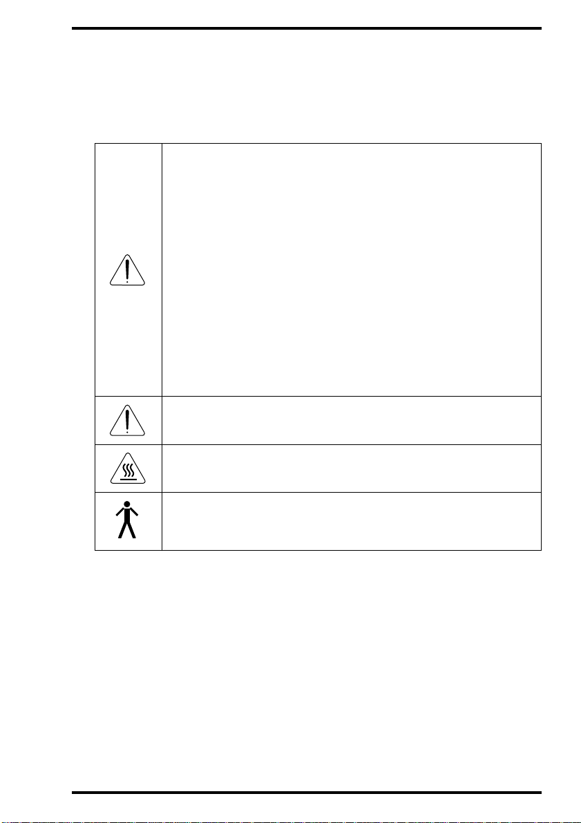
Markings and labels
Always take into account the markings and labels provided on the inside and
outside of the machine. A brief overview of these markings and labels and
their meaning is given below.
Safety warning, indicating that the CR 75.0 manuals should be
consulted bef ore making any connecti ons to other equipment. The
use of accessory equi pm ent not complying with the equivalent
safety requirem ents of this Digitizer ma y lead to a reduced level of
safety of the res ulting system. Consideration relating to the choice
of accessory equipment shall include:
• Use of the accessory equipment in the patient vicinity,
• Evidence that the safety cer tif icati on of the acc esso ry equip ment
has been performed in accordance wit h the appropr iate IEC 6011 and IEC 601-1-1 harmonized national standard.
In addition all con figurations must comply with the medical
electrical systems standard IEC 601-1-1. The party that makes the
connections acts as system configurator and is responsible for
complying with t he systems standard .
If required contact your local servi ce organization.
In order to reduce the ri sk of electric shock, do not r em ove any
covers.
Caution hot:
Keep hands clear from the erasure unit.
2242A EN 20040303
Type B eq uipme nt:
Indicates that th e CR 75.0 complies with the limits for type B
equipment.
9

Supplementary protective earth connector:
Provides a connection between the CR 75.0 and the potential
equalization busbar of the electrical system as found in medical
environments. This plug should never be unplugged before the
power is turned off and the power plug has been removed.
Intergrounding connector:
Provides a connect ion between the Digitizer and other equipment
which might exhibit minor ground potential differences. These
differ ences may degrade the quality of communication between
different equipment. Never remove connections to this terminal.
Protecti ve eart h (ground):
Provides a connect ion between the Digitizer and the protective
earth of the mains . Do not remove this connection, because this
will have a negative influence on the leakage current.
Power on
Power off
Note that the power cord has to be disconnected from the wall
outlet in order to disconnect the unit entir ely from the mains.
Precautions for use in USA only:
Make sure that the circuit is single-phase center-tapped, if the
Digitizer i s connected to a 240 V/60 Hz source instead of a 120 V/
60 Hz source.
10
• You can hurt your fingers if they are caught between the ADC Cassette and the
edge of the input slot. Insert the cassette in the input buffer as described in
‘Reading an ima ge plat e’ on page 26. At all times, keep your fingers clear of the
input slot. As soon as the CR 75.0 takes in the cassette, release it.
2242A EN 20040303
TÜV safety issues
Accessory equipment connected to the analog and digital interfaces must be
certified according to the respective IEC standards (e.g. IEC 950 for data
processing equipment and IEC 601-1 for medical equipment). Furthermore
all configurations shall comply with the valid version of the system standard
IEC 601-1-1. Everybody who connects additional equipment to the signal
input part or signal output part configures a medical system, and is therefore
responsible that the system complies with the requirements of the valid
version of the system standard IEC 601-1-1. If in doubt, consult your local
service organization.
Safety instructions for laser products
The CR 75.0 is a Class 1 Laser Product. It uses a 2x50 mW laser diode,
classification class IIIb.
Under normal operating conditions - when both doors are closed - there can
be no laser radiation outside the CR 75.0. It is nonetheless imperative that
the local radiation safety regulations regarding the protection of staff against
scattered radiation are complied with, if the CR 75.0 is located in the
immediate vicinity of an X-ray room.
Open the front left and right door only to solve cassette or image plate jams.
When you open either of the doors, the power supply of all critical
components is switched off automatically as a precaution.
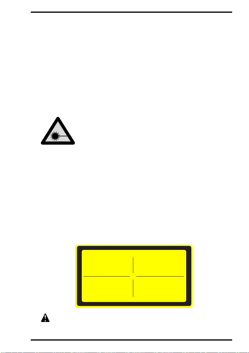
Observe the Caution instructions on the Optical module label:
2242A EN 20040303
CAUTION!
CLASS 3B LASER RADIATION:
WHEN OPEN AVOID DIRECT
EXPOSURE TO THE BEAM!
VORSICHT !
LASERSTRAHLUNG KLASSE 3B:
WENN ABDECKUNG GEÖFFNET
NICHT DEM STRAHL AUSSETZEN!
User interventions other than those described in this manual can be
hazardous with regard to laser radiation.
CUIDADO!
RAYO LASER CLASE 3B:
EVITAR LA EXPOSICIÓN AL HAZ
CUANDO LA TAPA ESTÁ ABIERTA.
ATTENTION!
FAISCEAU LASER CLASSE 3B:
QUAND CAPOT OUVERT ÉVITER
DE S´EXPOSER AU RAYÓN!
11

Safety compliance
The CR 75.0 complies with:
• the general safety regul ati ons:
EN 60601-1:1990+A1:1993+A2:1995,
IEC 601-1:1988+A1:1991+A2:1995,
IEC 601-1-1 / EN 60601-1-1,
EN 60601-1-2:1993,
UL 2601-1 Second Edition,
CAN/CSA 22.No.601.1-M909;
• the laser safety regulations:
EN 60825,
DHHS/FDA 21 CFR, Parts 1040.10 and 1040.11,
ANSI Z 136-1980.
12
2242A EN 20040303

Operati ng m odes
The CR 75.0 can be operated in three modes: operator mode, key-operator
mode and service mode.
Operator mode
The operator mode groups all basic functions which are aimed at
radiographers:
• Reading an image plate;
• Reading an emergency image plate;
• Re-eras ing an image plat e.
A normal image plate is read automatically after it is placed in the CR 75.0
input buffer; the other functions of the operator mode can be accessed via the
keypad. All functions of the operator mode are described in Chapter 2, ‘Basic
operation (‘Operator mode’)’.
Key-oper ator mod e
The key-operator mode groups advanced functions which are aimed at
technicians.
The key-operator mode can be accessed via the Key-operator key on the
keypad and is menu-driven. The key-operator functions are described in
Chapter 3, ‘Advanced operation (‘Key-operator mode’)’.
Service mode
The service mode functions are reserved for trained service personnel. They
are password protected.
2242A EN 20040303
13
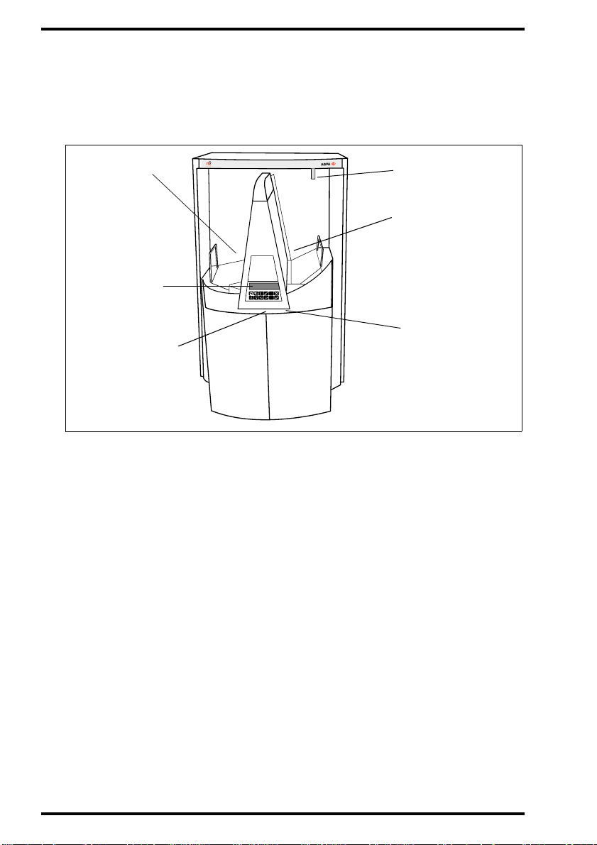
The user inter f ace
Main components of the Digitizer
Cassette
output buffer
Keypad
with display
Serv ice connect or
MUSICA
Status indicator
Cassette
input buffer
Main switch
CR 75.0
The main components of the CR 75.0 are:
" Cassette input buffer
The cassette input buffer accepts up to 10 cassettes - even of different sizes for digitizing and up to 9 cassettes for erasure.
" Keypad
14
As the handling of the cassettes is fully automated, normal operation is a
zero-button operation. The keys on the keypad are only used to activate
special functions such as reading an emergency image plate or erasing an
image plate.
2242A EN 20040303

" Status indicator
A light indicates the status of the CR 75.0.
" Cassette output buffer
The cassette output buffer receives cassettes which have been handled by
the Digitizer.
The control panel
The control panel of the CR 75.0 consists of a backlit LCD display and 10
keys.
As the handling of the cassettes is fully automated, normal operation is a
zero-button operation. Only when you are performing special functions or in
the event of problems (e.g. a cassette or image plate jam), you will need the
keys.
2242A EN 20040303
15

The keypad
Special functions can be accessed via the keypad. The keypad features the
following keys:
Emergency
key
Erase key
Key-operator
key
Service key
Escape key
Confirm key
T o gi ve an i mage the st atus ‘e merge ncy’ when it is
sent to the image proce ssing station.
To erase images without digitizing them.
This must be done if:
• an image plate has not been used for more th an
3 days;
• an image plate has been exposed to an
exceptionally high X-ray dose.
To access advanced functions (‘key-o perator
functions’).
To access service-level functions.
Reserved for trained service personnel.
To quit the curren t function or exit a menu without
saving modifications.
In key-operator mode:
• to select a menu.
• to accept an entry in a menu and go back to
operator mode.
16
2242A EN 20040303

Up key
Down key
Left key
Right key
• To move the cursor to the previous entry field.
• To scroll upwards.
• To i ncrement the number in a numeric entr y
field.
• To move the cursor to the next entry fie ld.
• To scroll downwards.
• To decrement the number in a numeric entry
field.
• To scroll backwards throu gh multiple choices
within a field.
• To move the entry position in a numeric al entry
field from right to le ft.
• To t oggle between values in a field.
• To scroll forwards through multiple choices
within a field.
• To move the entry position in a numeric al entry
field from lef t to right.
• To t oggle between values in a field.
2242A EN 20040303
17

The display
The CR 75.0 control panel has a backlit LCD display with 8 lines of 40
characters each. Its lay-out depends on the operating mode.
" In operator mode, the display has dedicated areas for specific information:
1
1
Set-up STATUS
8.1
Patient_Last_Name Sub_Exam
8.2
Patient_Last_Name Sub_Exam
8.3
Patient_Last_Name Sub_Exam
Station Name ERROR
24
1ST MESSAGE
2nd Mess ag e
3
OPERA TIO N MODE
7
1
Set-up of image processing station:
• [blank]: Default image processing stati on selected.
• Off line: Tr ansmission to all image processing stations di sabled.
• [process.stat ion] not ready: Image processing station not available.
• [process.stat ion] rerouted: Images rer outed to other image processing
station.
2 Ty pe of message
3 Extra comment or action to take
4 System status:
• READY: The CR 75.0 is ready for operation.
• BUSY: The CR 75.0 is busy with scanning or erasing.
• ERROR: An error has occurred.
• LOCKED: id.
• WARNING: id.
5
6
18
2242A EN 20040303

5
Operation mode:
• [blank]: Normal operat ion mode.
• EMERGENCY: Emergency function for image plates with I D data.
• ERASURE: Re-erasure function.
Error status: service code (SERVICE XXXXX) or error code (CODE
6
XXXXX)
7
St ati on name of the CR 75.0
Identifier of ima ge plate being treated:
8.1
After image ID data is read;
8.2
During scanning of image plate and transmittal of image data;
8.3
During transmittal of image data to image proc essing station.
If the system has been idle for 5 minutes, the backlit LCD display dims. The
display lightens if:
• The display message changes, e.g. if the Digitizer receives a message from the
image processing station.
• You place a cassette in the input buffer.
• You press a key on the keypad.
" In key-operator mode, operation is menu driven. The menu displays the
key-operator functions, the active keys, and the service code.
2242A EN 20040303
Queue management
Digitize r se t- up
Date and Time
1
Send test image
System info
Install
Save confi guration
Fast preview
1
Key-operator functions
2 Active keys
3
Service code
KEY-OPERATOR
MENU
: quit
: ok
: select
SERVICE XXXXX
2
3
19

The status indicator
The light at the top of the CR 75.0 indicates the status of the CR 75.0.
Color
Green
Constant/
Flashing
Constant
Flashing
Status Action
Ready. Proceed.
Busy (treating image
plate).
Proceed.
• Check display for messages.
Constant
Error.
• Refer to ‘General procedure
in case of malfunct ion’ on
page 41.
• Locked or warning.
Red
Flashing
• Power on/self-test
in progre ss.
• Key-operator mode.
• Service mode.
• CR 75.0 not
• Check display for messages.
• Refer to ‘General procedure
in case of malfunct ion’ on
page 41.
connected to image
processing devi ce.
Audio signals
The CR 75.0 gives status information via beeps. The length of the beep
indicates the response of the system to a key command.
• A short beep means that CR 75.0 has accepted the key command and is
starting the operation.
• A long beep means that you have pres sed a non-active key or that the
CR 75.0 has rejected the key command.
• An interval beep accompanies an error, locked or warning message.
20
2242A EN 20040303
 Loading...