

Page 1

HEALTHCARE
Imaging Services
ReadMeFirst
How to print and add Comments
1 Printing single Pages, Chapters or the complete Manual
IMPORTANT:
This PDF manual is screen optimized – nevertheless it is possible to print single pages,
single chapters or the complete manual on paper size DIN A4 or Letter.
Some pages – especially circuit diagrams for equipment – have been created on paper
size larger than DIN A4/Letter. Printing these pages on DIN A4/Letter may result in
reduced legibility.
Preferably print circuit diagrams on a DIN A3/ANSI B (Ledger) printer, if available.
1.1 Printing single Pages or Chapters
To print single chapters or pages of a chapter proceed as follows:
(1) Click the bookmark of the desired chapter
(2) Write down or remember the shown page number
(3) Go the end of the section or desired range of pages
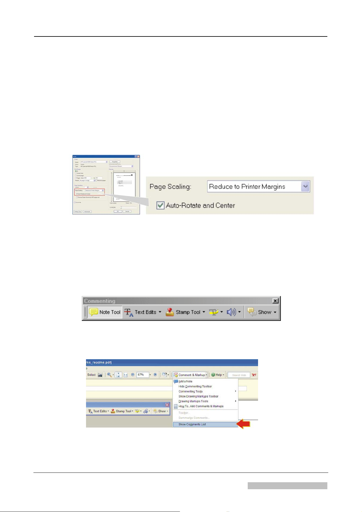
(4) Select "Print"
(5) Select the page range
(6) Select "Reduce to printer margins" and "Auto-rotate and Center".
(7) Select “OK”
NOTE:
“Reduce to printer margins” may be named on other Adobe Reader versions
“shrink to printable area” or “shrink oversized pages to paper size”
2007-05-31 printed in Germany
Agfa Company Confidential
Document Node ID: 16099429
Copyright © 2006 Agfa-Gevaert HealthCare
Page 2
1.2 Printing the complete Service Manual
To print the complete service manual proceed as follows:
(1) Select "Print"
(2) Select “All”
(3) Select "Reduce to printer margins" and "Auto-rotate and Center".
(see NOTE previous page)
(4) Select “OK”
ReadMeFirst
2 Adding Comments
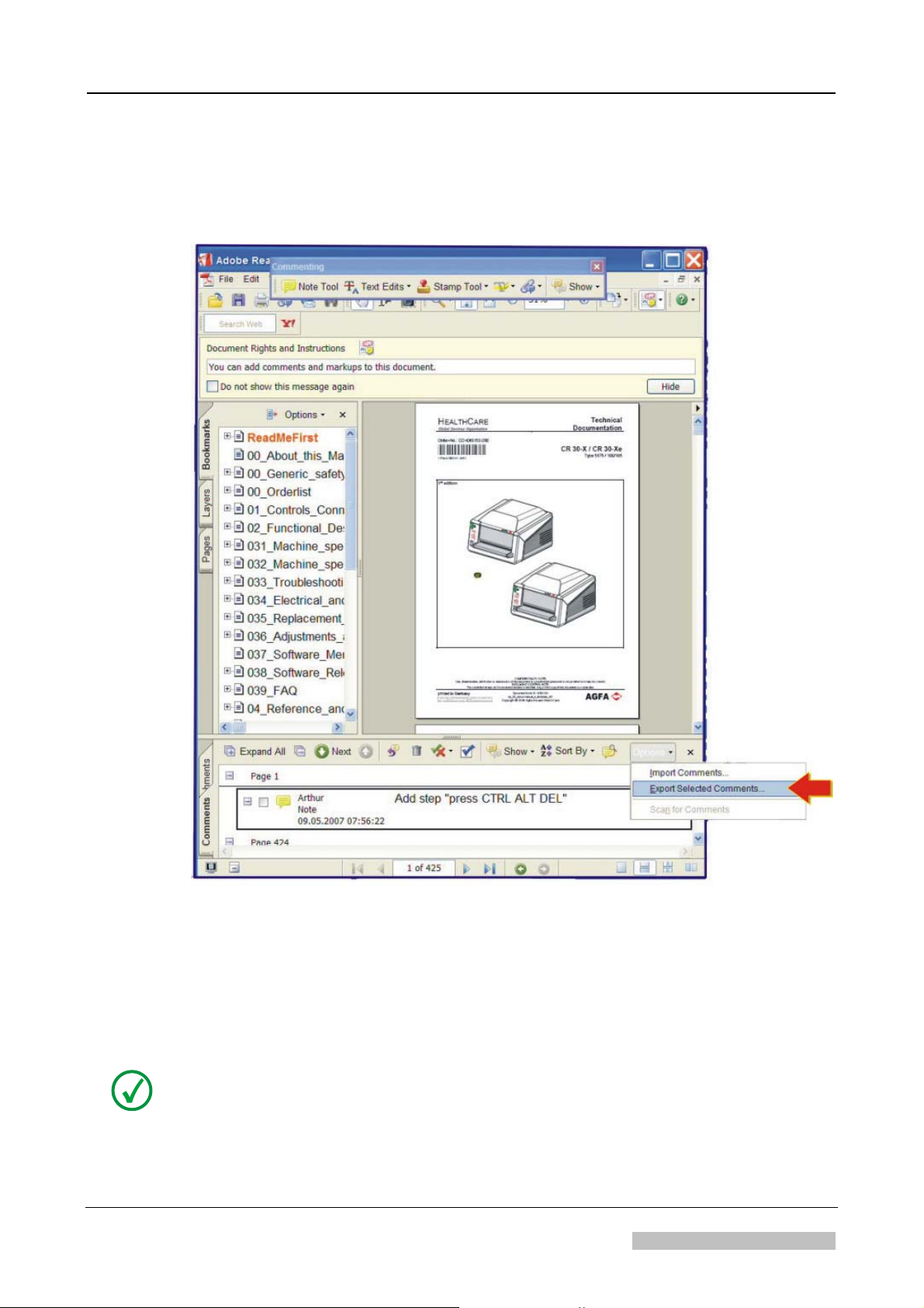
• If you open this file in an Adobe Reader version ≥ 7, the comment toolbar will
show-up.
• This allows adding comments, to highlight or underline text and many more text
manipulations.
2.1 How to export your Comments
(1) In the drop down menu “Comment & Markup” select "Show comments List"
(2) Select the desired comments: Press the CTRL-key for multiple selections.
The controlled version of this document resides on MedNet. Any printed copy of this document is uncontrolled.
DOCUMENT CONTROL NOTE:
Revision 1 How to print and add Comments Page 2 of 3
2007-05-31 Agfa Company Confidential
Page 3
ReadMeFirst
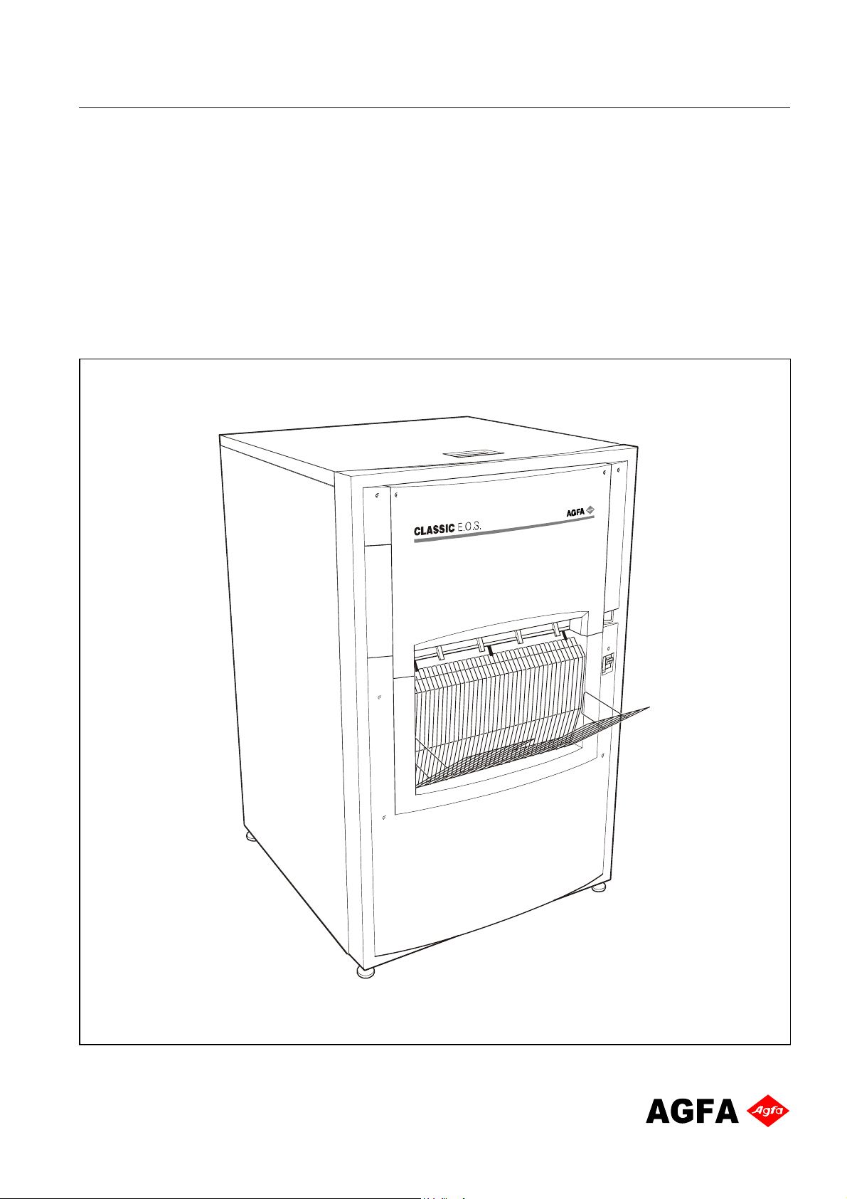
(3) Select “Options - Export Selected Comments”
(4) Save the file with any name
2.2 How to import Comments
(1) In the drop down menu “Comment & Markup” select "Show comments List"
(2) Select “Options - Import Comments”
(3) Browse for the comments file and press “select”
NOTE:
The imported comments possibly appear on different pages, if the file where the
comments have been imported has a different number of pages.
DOCUMENT CONTROL NOTE:
The controlled version of this document resides on MedNet. Any printed copy of this document is uncontrolled.
Revision 1 How to print and add Comments Page 3 of 3
2007-05-31 Agfa Company Confidential
Page 4

Page 5
HEALTHCARE
Global Services Organisation
Order No.: DD+DIS301.03E
*1WACEX1*
1 piece WACEX MA1
Edition 6
Technical
Documentation
Classic E.O.S.
Type 5270 / 100
as of SN 4500
Classic E.O.S. CL
Type 5270 / 105
as of SN 1138
printed in Germany 02 / 2005
Agfa Company Confidential
R
D
C
.
2
0
_
0
0
0
0
1
_
0
7
2
5
Page 6

Page 7
HEALTHCARE
Global Services Organisation
Order No.: DD+DIS301.03E
*1WACEX1*
1 piece WACEX MA1
Technical
Documentation
Classic E.O.S.
Type 5270 / 100
as of SN 4500
Classic E.O.S. CL
Type 5270 / 105
as of SN 1138
6. Edition
Ordering of spare parts Phone: xx49 - (0)89 - 6207 -3760
and spare part kits: Fax: xx49 - (0)89 - 6207 -7388
Ordering of documentation: Phone: xx49 - (0)89 - 6207 -3553
Caution:
This system uses mains voltage. Please observe the pertinent safety instructions.
These instructions describe adjustments and routines which must only be
performed by qualified technical personnel.
Note:
Electrical repairs and connections must only be made by certified electricians.
Mechanical repairs and connections must only be made by certified technicians.
CE Declaration:
According to the medical directives the CE Declaration
(CE Conformity) becomes void if the product is modified without permission of the
manufacturer!
R
D
C
.
2
0
_
0
0
0
0
1
_
0
7
2
5
This applies to all parts, not only the safety devices!
printed in Germany 05 / 2005
Agfa Company Confidential
AGFA-GEVAERT AG HE/S&S - GSO
Tegernseer Landstr. 161 D-81539 Munich
Page 8
Contents
Pictographs and conventions for this documentation
This documentation uses certain conventions (pictographs, styles) to help you find information
faster and easier.
0. Order list
1. Installation preparations
2. Controls and connectors
3. Installation / start-up
4. Operating instructions
5. Theory of function
6. Repair and Service
7. Reference and circuit diagrams
8. Spare parts list
9. Accessories
10. Modifications
11. Technical standard modifications
Meaning of the pictographs
High voltage!
Attention!
Info
Hint
Required
spare part
Required
time
Waiting time
Required
tools
Removal
Installation
Mechanical adjustment
Electrical adjustment
Calibration
Conventions
Activity Type face Example
Instruction,
Explanation
Mouse activities,
or Return key
Text input via keyboard
required
Switch on machine
<omni-cd.exe>
vips
Switch on machine
Doubleclick the icon
<omni-cd.exe>
Enter vips and click
<Continue>
12. Maintenance
13. Field Service Bulletins
14. Installation planning
15. Glossary / key word index
Agfa Company Confidential
Page 9
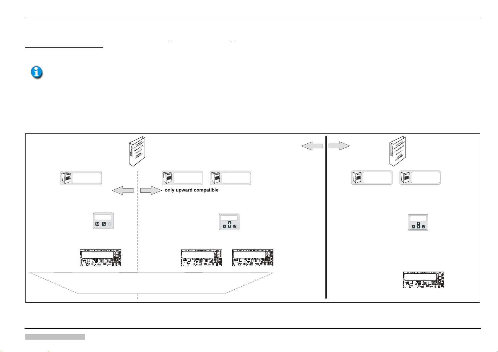
DD+DIS441.04E General Information
_
_
Classic E.O.S. / Classic E.O.S. CL (Type 5270/100/105) Edition 6
th
The 6
edition is the Service Documentation applying to the machines > SN4500 (Type 5270/100) or > SN1138 (Type 5270/105)
It is not a replacement for Edition 5.
The 5th edition remains the Service Documentation applying to the machines < SN4500 (Type 5270/100) or < SN1138 (Type 5270/105)
and it includes the information about technical modifications in the machines up to these serial numbers.
All previous information regarding the serial number of Type 5270/105 (SN 1500) to differentiate compatibility
is void. The new valid threshold for compatibility differentiation of Type 5270/105 is the serial number SN 1138.
This serial number refers to the complete documentation.
Edition 6 provides information about technical modifications in the production standard as of serial numbers 4500 or 1138 respectively.
The technical modifications are:
x A new Control Board (with label F8.5270.7890) has been introduced, and this board only works with Software Version CLLC1107 and up. It is not compatible with the previous control boards and their software.
x The water circulation pump became an option.
x A level sensor in the fixer tank 2 has been added.
x The 24V crossflow fan has been replaced by crossflow fan with 230V.
TYPE 5270/100
only downward compatible
Software versions:
Techn. characteristics:
Control board:
SN 1001
CEOS1117 - CEOS1801
- 3-key control panel
As of CEOS1714:
- Must calibration
- Selection of application
C210
MC31
R
e
v
IC57
D
e
p
l
ST55
MC29
u
l
C
t
c
h
MC28
MC27
y
l
p
S
p
u
ST63
ST57
D
r
a
i
n
ST89
F
a
n
2
ST90
SI2
ST85
ST66
MC13
ST62
MC2
ST54
S1
MC20
MC34
IC52
F8.5270.7750._
ST64
ST65
ST67
ST68ST69
ST70
ST53
IC51
IC50
ST88
IC63
ST73ST72
ST71
ST81
IC78
ST76
ST79
ST74
ST82
R464
R465
ST15
ST77
ST78ST75
IC79
ST87
IC88
Contrast
Brightness
Film Out
SI9
D48
MC32
MC22
ST4
RS4 RS1RS3
SI8
R477
L11
MC16
MC4
MC17
ST5
TY2
R410
C80
D50
BU9
12V2
+24V2
C64
ST45
C63
Circ.Fan1
RS2
RS9
MC24
MC23
D49
TY1
MC3
+24V
C79
BU1
D2
BU4
IC65
+12MOT
IR
Blowe
HeatF
HeatD
R476
R380
RS19
RS21
RS23
SI12
MC35
MC36
R377
RS20
RS24
R485
RS22
R475
R381
R378
R379
RS6 RS7RS5
RS8
SI1
SI3SI5
SI10
SI11 SI6 SI7
BU10
ST86
XK1
BU7
BU6
fuj07903E.cdr
Software version:
Techn. characteristics:
Edition 5
DD+DIS324.00D/E/F
TYPE 5270/100
SN 2200
Software versions:
Techn. characteristics:
IC57
ST55
MC29
MC28
MC27
Steuerkarten:
ST63
ST89
ST90
ST85
ST66
S1
IC52
F8.5270.7750._
ST53
IC50
ST81
ST82
R464
R465
ST15
IC88
ST87
Contrast
Brightness
Film Out
EOSUNIV1007
- Must calibration
- Selection of application
only downward
compatible
TYPE 5270/105
SN 1001
MEOS1201 - MEOS1401
- 4-key control panel
Software versions:
Techn. characteristics
- Current sensor
- Integrated repair routine
C210
ST57
SI2
ST54
ST64
ST65
IC51
IC63
IC78
IC79
- Cross-flow fan 24V
R477
D48
L11
MC32
MC31
MC16
e
R
v
l
D
e
p
MC4
MC17
C
l
u
t
c
h
TY2
R410
C80
l
y
p
p
u
BU9
S
+24V2
12V2
C64
D
in
r
a
ST45
C63
F
a
n
2
Circ.Fan1
MC22
MC13
ST62
MC2
TY1
MC3
MC20
+24V
MC34
C79
BU1
D2
IC65
ST4
ST67
ST68ST69
ST70
+12MOT
ST88
HeatD
ST73ST72
ST71
R476
R380
SI12
MC35
MC36
ST79
ST76
ST74
RS24
R485
RS22
R475
R378
RS4 RS1RS3 RS6 RS7RS5
RS8
ST77
ST78ST75
SI11 SI6 SI7 SI1
SI10
RS2
BU10
RS9
ST86
BU7
C210
SI9 SI8
ST55
ST5
D50
ST66
MC24
MC23
D49
S1
BU4
ST53
IR
HeatF
Blowe
RS19
RS21
RS23
R377
RS20
R379
R381
ST15
ST87
SI3SI5
Film Out
XK1
BU6
fuj07903E.cdr
MC32
MC31
D
e
p
l
R477
e
v
R
IC57
MC29
C
l
u
t
c
h
MC28
MC27
ST89
ST82
R410
p
p
l
y
u
S
BU9
ST63
ST57
12V2
D
r
a
i
n
ST45
a
n
F
ST90
2
SI2
ST85
Fan1
Circ.
MC22
ST62
MC13
MC2
ST54
MC20
MC34
IC52
F8.5270.7950.
ST64
ST65
ST67
ST68ST69
ST4
ST70
IC51
IC50
ST88
IC63
ST73ST72
ST71
ST81
IC78
ST76
ST79
ST74
R464
R465
ST77
ST78ST75
RS4 RS1RS3 RS6 RS7RS5
IC79
IC88
RS2
Contrast
Brightness
RS9
SI9 SI8
D48
L11
MC16
MC4
MC17
ST5
TY2
C80
D50
+24V2
C64
C63
MC24
MC23
D49
MC3
TY1
+24V
C79
BU1
D2
IC65
BU4
+12MOT
IR
HeatF
HeatD
Blowe
R476
R380
RS19
RS21
RS23
SI12
MC35
MC36
R377
RS20
RS24
R485
RS22
R475
R379
R381
R378
RS8
SI11 SI6 SI7 SI1
SI3SI5
SI10
BU10
ST86
XK1
BU7
BU6
fuj07903E.cdr
only upward
compatible
TYPE 5270/100
Control board:
SN 4500
Edition 6
DD+DIS301.03D/E/F
TYPE 5270/105
SN 1138
CLLC1107
- 4-key control panel
- Current sensor
- Integrated repair routines
- Selection of applications
- Water circulation pump
becomes optional
- Level sensor for fixer tank 2
- Cross-flow fan 230V
C210
MC32
BU9
MC22
ST4
RS4 RS1RS3 RS6 RS7RS5
SI9 SI8
R477
D48
L11
MC16
MC4
MC17
ST5
TY2
R410
C80
D50
12V2
+24V2
C64
ST45
C63
MC24
Circ.
RS2
RS9
MC23
D49
TY1
MC3
+24V
C79
BU1
D2
IC65
BU4
+12MOT
IR
HeatF
HeatD
Blowe
R476
R380
RS19
RS21
RS23
MC35
MC36
SI12
R377
RS20
RS24
R485
RS22
R475
R379
R381
R378
RS8
SI11 SI6 SI7 SI1
SI3SI5
SI10
BU10
ST86
XK1
BU7
BU6
fuj07903E.cdr
p
l
D
e
v
e
R
MC31
IC57
ST55
MC29
c
h
C
l
u
t
MC28
MC27
S
u
p
p
ly
ST63
ST57
r
a
D
i
n
ST89
F
ST90
a
SI2
n
2
ST85
ST66
Fan1
ST62
MC13
MC2
ST54
S1
MC20
MC34
IC52
F8.5270.7890.
ST64
ST65
ST67
ST68ST69
ST53
IC51
IC50
ST88
IC63
ST73ST72
ST71
ST81
IC78
ST74
ST76
ST79
ST82
R464
R465
ST15
ST77
ST78ST75
IC79
ST87
IC88
Contrast
Brightness
Film Out
ST70
5270_10000_003-e.cdr
Edition 6, Revision 1 Classic E.O.S. / Classic E.O.S. CL Chapter 0 / I
Agfa Company Confidential (Type 5270 / 100 / 105)
Page 10

Page 11
Order List for Documentation
Order List for Documentation Classic E.O.S.
Type 5270/100, from SN4500
Classic E.O.S. CL
Type 5270/105, from SN1138
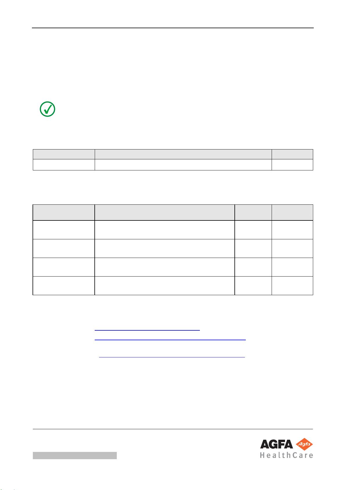
NOTE:
Daily updated order lists are available in MedNet.
Order number for a complete Service Manual:
Order number Edition
DD+DIS301.03E Complete Service Manual 6
Order numbers for separately available chapters of the Service Manual:
Order number Contents Revision
of document
Approval Date
DD+DIS302.03E Chapter 12:
Maintenance Instructions, Edition 6
DD+DIS303.03E Chapter 14:
Installation Planning, Edition 6
DD+DIS022.05M Chapter 08:
Spare Parts List
DD+DIS060.03E Chapter 08:
Spare Parts List, Thoramat Docking Unit
Access to MedNet GSO Library:
• *IntraNet: http://docs.agfanet/mednetcso-library
• *ExtraNet: http://extranet.agfa.com/bu/mi/mednet/mednetcso.nsf
* to request an account to the MedNet GSO Library go to:
http://intra.agfanet/bu/mi/mednethelp.nsf/EN/gettingaccess.htm
Inquiries:
• Phone + 49 89 6207 3949 Fax +49 89 6207 7274
0 2004-03-12
0 2004-02-05
4 2007-11-28
3 2006-12-08
The controlled version of this document resides on MedNet. Any printed copy of this document is uncontrolled.
2007-11-28 printed in Germany
Agfa Company Confidential
DOCUMENT CONTROL NOTE:
Document Node ID: 14037585
eq_00_orderlist_e_template_v04
Copyright © 2007 Agfa HealthCare N.V.
Page 12
Checklist for Completeness
Checklist for Completeness Classic E.O.S. / Classic E.O.S. CL
Type 5270/100/105
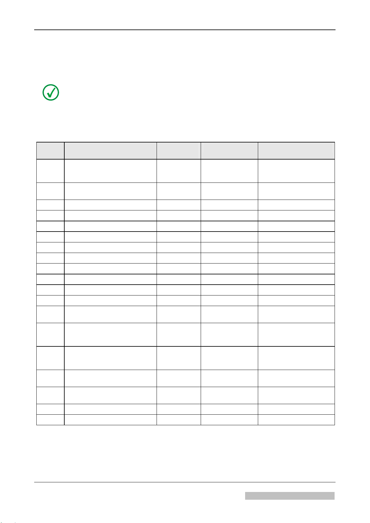
NOTE:
Verify latest level and completeness of your Service Manual by means of this checklist
for completeness.
Only the document numbers listed here are valid. Discard documents with different
numbers if necessary.
Chapter Order number / Designation Revision
of document
Approval date Pages
0 Order list
Checklist for completeness
List of Service Bulletins
0 DD+DIS301.03E 0 2004-03-12 Cover sheet and list of
1 DD+DIS301.03E 0 2004-03-12 1/I, 1/1 – 1/13
2 DD+DIS301.03E 0 2004-03-12 2/I, 2/1 – 2/6
3 DD+DIS301.03E 0 2004-03-12 3/I-II, 3/1 – 3/57
4 Intentionally left blank - - -
5 DD+DIS301.03E 0 2004-03-12 5/I-II, 5/1 – 5/42
6.1 DD+DIS301.03E 0 2004-03-12 6.1/I, 6.1/1 – 6.1/8
6.2 DD+DIS301.03E 0 2004-03-12 6.2/I, 6.2/1 – 6.2/10
6.3 DD+DIS301.03E 0 2004-03-12 6.3/I, 6.3/1 – 6.3/24
6.4 DD+DIS301.03E 0 2004-03-12 6.4/I, 6.4/1
6.5 DD+DIS301.03E 0 2004-03-12 6.5/I-II, 6.5/1 – 6.5/28
6.6 DD+DIS301.03E 0 2004-03-12 6.6/I, 6.6/1 – 6.6/6 (A3)
6.7 DD+DIS131.05E 2 2005-05-03 6.7/I,
- 2007-11-28 0/1-4
contents
6.6/7 – 6.6/15
6.7/1 – 6.7/2,
6.7/3
7 DD+DIS301.03E
F1.5272.7005.0
Overview Control Board PCB1
8 DD+DIS022.05M
DD+DIS060.03M
9 DD+DIS301.03E
DD+DIS309.00E
10 Intentionally left blank - - -
11 DD+DIS441.04E 1 2004-12-22 11/I, 11/1
DOCUMENT CONTROL NOTE:
The controlled version of this document resides on MedNet. Any printed copy of this document is uncontrolled.
0 2004-03-12 7/I, 7/1-13
Sh. 1-1 (A1)
(A3)
4
3
0 2004-03-12 9/I
2007-11-28
2006-12-08
8/1 - 8/76
8/1 – 8/22
Cover sheet, 9/I, 9/1 – 9/8
2007-11-28 Classic E.O.S. / Classic E.O.S. CL Chapter 0 / 2
Type 5270/100/105 Agfa Company Confidential
Page 13
Checklist for Completeness
Chapter Order number / Designation Revision
of document
12 DD+DIS302.03E 0 2004-03-12 Cover sheet
Approval date Pages
12/I, 12/1 - 12/25
Checklist 1-3
13 SB 01 DD+DIS157.04E
SB 02 DD+DIS249.04E
SB 03 DD+DIS277.04E
SB 04 DD+DIS288.04E
SB 05 DD+DIS214.04E
SB 06 DD+DIS184.05E
SB 07 DD+DIS009.07E
SB 08 DD+DIS223.07E
14 DD+DIS303.03E 0 2004-02-05 Cover sheet
15 DD+DIS301.03E 0 2004-03-12 15/I, 15/1 – 15/3
n.a. 2004-05-07
2004-08-04
2004-08-31
2004-08-31
2004-07-06
2005-07-06
2007-01-29
2007-10-23
13/1-5
13/1-4
13/1-/3
13/1-/2
13/1-/2
13/1-/3
13/1-/3
13/1-/15
14/I-II, 14/1 – 14/41
The controlled version of this document resides on MedNet. Any printed copy of this document is uncontrolled.
DOCUMENT CONTROL NOTE:
2007-11-28 Classic E.O.S. / Classic E.O.S. CL Chapter 0 / 3
Type 5270/100/105 Agfa Company Confidential
Page 14
List of Service Bulletins
List of Service Bulletins Classic E.O.S. / Classic E.O.S. CL
Type 5270/100/105
• The following SB’s are valid:
SB Document number Contents Revision
of document
SB 01 DD+DIS157.04E Control Board PCB1 (CM+9 5270 9450 0) and
Processor SOFTWARE CLLC1107
(CM+9 5270 9410 0) available as Spare Part
SB 02 DD+DIS249.04E Introduction of Processor Software CLLC_1203
Order Number: CM+9 5270 9410 1
Control Board PCB1 incl. CLLC_1203
Order Number: CM+9 5270 9450 1
SB 03 DD+DIS277.04E Magnet Not Sufficiently Fixed in the Machine
Cover
SB 04 DD+DIS288.04E Introduction of Anti-Algae-Unit
Type: 5279/100
SB 05 DD+DIS214.04E Installation of the Tank Reinforcement
CM+9 5270 9071 0
This document describes the installation of a tank
reinforcement that prevents bending of the
intermediate tank walls.
SB 06 DD+DIS184.05E Service 574:
“IR heater in dryer defective” due to measuring
error caused by wrong cable positioning at the
Current Sensor Board PCB2.
0
0
0
0
0
0
SB 07 DD+DIS009.07E Manufacturer’s Warning about Ground Fault
0
Interrupters with Possibly Higher Trigger Current.
SB 08 DD+DIS223.07E Empty Battery of the Clock Chip Causes Incorrect
0
Date and Incorrect Time Display Followed by a
Calibration Request
• The following SB's are no longer valid
(integrated in the chapters of the Service Manual, or technically obsolete):
SB Document number Contents Revision
of document
-- -- -- --
The controlled version of this document resides on MedNet. Any printed copy of this document is uncontrolled.
DOCUMENT CONTROL NOTE:
2007-11-28 Classic E.O.S. / Classic E.O.S. CL Chapter 0 / 4
Type 5270/100/105 Agfa Company Confidential
Page 15

Preinstallation
1
Section 1
contains all important preinstallation data for the machine:
• Inspection of the packing material for transport damage and complete
shipment
• Unpacking and packing notes
• Machine positioning at the installation site
• Requirements on the installation site
• Connection data (electrical, if necessary, connections to chemical supply and
disposal, fiber optic connections)
Make sure to study this section and before starting the installation check if all
preparations have been made as specified.
Section 1
Page 16

Page 17

DD+DIS301.03E Installation Preparations
Chapter 1
Contents
1 Safety ......................................................................... 1
2 Installation Preparations ..........................................3
2.1 Machine transport ...................................................................3
2.2 Checking the shipment ........................................................... 3
2.3 Transport check....................................................................... 3
2.4 Checking safety indicators on the machine box ..................3
2.5 Transport path .........................................................................4
2.6 Required space at the installation site ..................................5
2.6.1 Classic E.O.S. Type 5270/100...........................................................5
2.6.2 Classic E.O.S. CL Type 5270/105 .................................................... 6
2.7 Unpacking ................................................................................7
2.8 Checking the type label ..........................................................8
2.9 Checking the accessory box ..................................................8
3 Technical Data........................................................... 9
3.1 Electrical data ..........................................................................9
3.2 Ambient and climatic conditions ...........................................9
4 Dimensions and Weights........................................ 11
4.1 Classic E.O.S. Type 5270/100 .............................................. 11
4.2 Classic E.O.S. CL Type 5270/105 ........................................11
5 Machine Standards and Directives........................ 12
5.1 Safety...................................................................................... 12
5.2 Radio interference suppression...........................................12
5.3 Electromagnetic compatibility.............................................. 12
5.4 Certificates and guidelines...................................................13
Edition 6, Revision 0 Classic E.O.S. / Classic E.O.S. CL Chapter 1 / I
Agfa Group Confidential (Type 5270 / 100 / 105)
Page 18

Page 19

DD+DIS301.03E Installation Preparations
1 Safety
General safety instructions
• The machine must only be used as described in the operating instructions.
Any other use may result in damage to the machine or may affect the
machine function with the consequence that the machine can no longer be
used as intended, and therefore presents a risk for patients, user, and
environment.
• The machine must only be operated by qualified personnel trained on the
machine.
• Ensure that only trained personnel have access to the machine.
• Ensure that the machine can always be supervised and that any tampering
is prevented.
• Repairs or modifications on the machine must only be performed by trained
service personnel authorized by Agfa.
• In case of visible damage on the machine housing the machine must not be
operated or used, and must immediately be disconnected from the mains.
• Built-in or external safety devices must not be circumvented or disabled.
• Disconnect the machine from the mains before starting any maintenance.
• If a mains connection is absolutely required these maintenance routines
must only be made by specially trained personnel.
• Like all technical devices, this machine must be operated, cared for and
serviced correctly as described in the documentation provided with the
machine.
• If the machine is not operated correctly, or if it is not serviced correctly,
Agfa will not be liable for any resulting disturbances, damage or injuries.
• When installing the machine make sure that either the mains plug or an all-
cable disconnecting device is provided in the internal installation close to
the machine and is easily accessible.
• If the machine is connected with other components or assemblies, Agfa will
guarantee safety only for combinations which are approved by Agfa.
• In case of conspicuous smoke or noises, immediately disconnect the
machine from the mains.
Special instructions for the handling of chemicals
• When handling chemicals, always observe the applying safety and
environmental regulations, as well as the operating and warning
instructions pertaining to these chemicals.
• Wear stipulated protective clothing and safety goggles.
• When disposing of chemicals and waste water, you must comply with the
local regulations concerning waste water and environmental protection.
• If photo-chemicals get in your eyes, proceed exactly according to the
warning instructions and/or the instructions published by the manufacturers
of the chemicals. If required, immediately rinse your eyes with cold water.
Afterwards see the doctor immediately.
• Avoid inhaling of chemical fumes. Make sure that there is sufficient
ventilation at the installation site of the machine, i.e. an air exchange that is
Edition 6, Revision 0 Classic E.O.S. / Classic E.O.S. CL Chapter 1 / 1
Agfa Group Confidential (Type 5270 / 100 / 105)
Page 20
Installation Preparations DD+DIS301.03E
at least ten times the room volume per hour.
• Always comply with the installation instructions.
• Verify tightness of all connections for chemicals and water, as well as
waste water, on the machine in regular intervals. At least check whenever
suggested in the operating instructions and/or service instructions.
• If solution gets into the inside of the machine (e.g. by spilling during tank
filling), the machine must immediately be disconnected from the mains and
cleaned thoroughly by the service personnel.
• Do not use additional chlorine or chlorine containing substances inside the
processor. The use of additional chlorine or chlorine containing substances
can lead to irreversible damage of the equipment. Using these substances
may void the manufacturers warranty.
The film processor must not be operated in the direct vicinity of the
patients as defined in EN60601-1 and IEC 601-1.
Adherence to safety regulations
• This film processor meets the safety requirements as defined in EN 60950:
1997 (IEC 950) and EN 60601-1-2: 1993, UL 1950 and CSA C22.2 No. 950
and has interference suppression as defined in EN 50081-1, EN 55011,
and FCC 47 Part 15, Subchapter B, Class A.
• The water connection complies with DIN 1988 / EN 1717:2001.
Chapter 1 / 2 Classic E.O.S. / Classic E.O.S. CL Edition 6, Revision 0
(Type 5270 / 100 / 105) Agfa Group Confidential
Page 21
DD+DIS301.03E Installation Preparations
2 Installation Preparations
2.1 Machine transport
The freight forwarder transports the machine up to the final installation site.
The responsible technician should be present during delivery.
2.2 Checking the shipment
Compare the labels on the boxes with the customer’s order list and the bill of
lading.
2.3 Transport check
Check the packing material for visible transport damage:
• dented edges
• damaged box
• torn fixing elements (metal straps, screws)
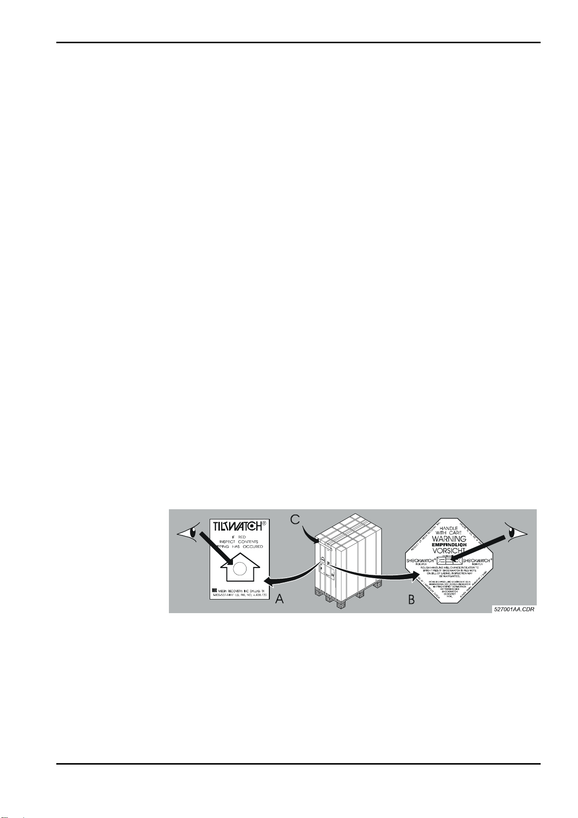
2.4 Checking safety indicators on the machine box
The machine is shipped on a pallet.
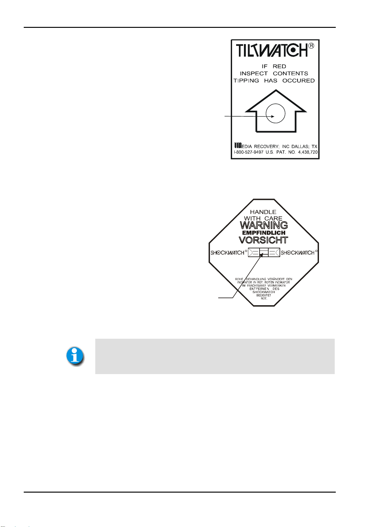
The box has a TILTWATCH indicator (A), a SHOCKWATCH indicator (B), and
a packing seal (C) attached.
They are attached to the outside of the box and indicate if the machine has
been tilted, was exposed to shocks, or has been opened during transport.
Figure 1
Edition 6, Revision 0 Classic E.O.S. / Classic E.O.S. CL Chapter 1 / 3
Agfa Group Confidential (Type 5270 / 100 / 105)
Page 22
Installation Preparations DD+DIS301.03E
If the machine was tilted, the
arrow head in the circle of the
TILTWATCH indicator (A)
changed from white to red.
A
5270_10001_002.cdr
Figure 2
D
A
L
LA
S, T
X
.
U
.S.
P
AT.
N
, FRA
H
GMB
X
E
KON
5270_10001_003.cdr
If the machine was subjected to
shocks, the square field in the
middle of the SHOCKWATCH
indicator (B) changed from white
to red.
NC.
I
OVERY,
OF MEDIA REC
PRODUCT
INDICATOR INDIKATOR
ROUGH HANDLING WILL CHANGE INDICATOR TO
IMPORT ED
BRIGHT RED. IF SHOCKWATCH IS RED NOTE
ON BILL OF LADING. INSPECTION MAY
B
Y / IMPOR
B
Model/Modell L-65
R R
BE WARRENTE D.
TIER T D
U
RCH
Figure 3
Note all detected damage in the installation report!
In case of a damaged machine make sure to keep the packing material for
proof (transport insurance)!
Send the damage report to the insurance company.
#
KFURT
40
68613
/
IN
A
M
2.5 Transport path
The film processor must fit through all doors and hallways on its transport path
to the installation site.
Classic E.O.S. / Classic E.O.S. CL
(Type 5270/100/105)
without pallet
with pallet
Chapter 1 / 4 Classic E.O.S. / Classic E.O.S. CL Edition 6, Revision 0
(Type 5270 / 100 / 105) Agfa Group Confidential
smallest door width
at least 73 cm (29 inch)
at least 82 cm (32 inch)
Page 23
DD+DIS301.03E Installation Preparations
2.6 Required space at the installation site
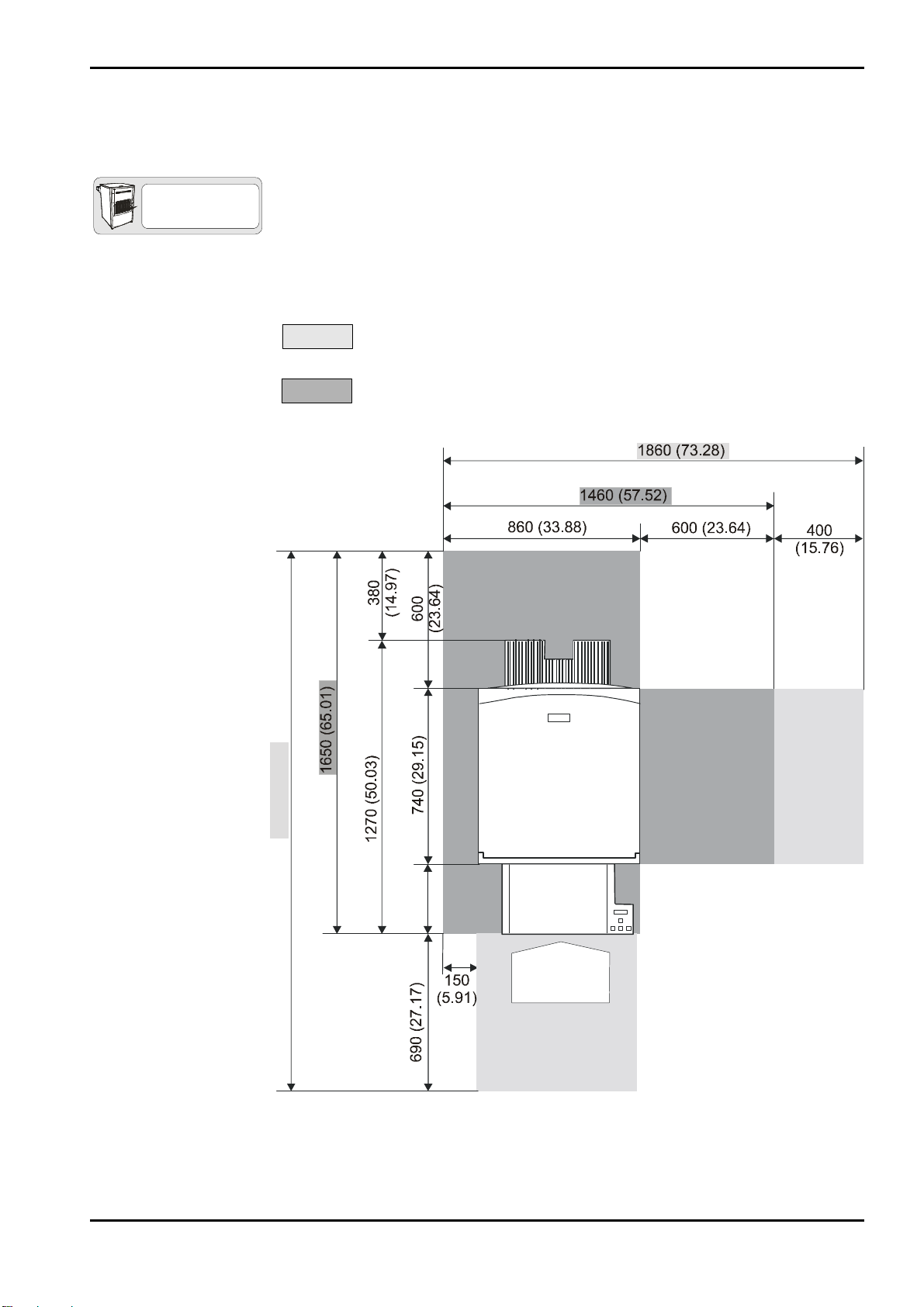
2.6.1 Classic E.O.S. Type 5270/100
The required floor space for the film processor (with feed table, chute and the
TYPE 5270/100
required clearance on the left) is 1260 x 860 mm (50.03 x 33.88 inch).
The free space indicated in the illustration must be guaranteed for repair and
maintenance, otherwise the time required for service will increase.
Optimum dimensions:
We recommend to plan on this free space.
Minimum dimensions:
Do not go below this minimum space.
2340 (92.19)
5270_10001_004.cdr
310
(12.21)
A
Figure 4
(A) Operation side
Dimensions in mm (inch)
Edition 6, Revision 0 Classic E.O.S. / Classic E.O.S. CL Chapter 1 / 5
Agfa Group Confidential (Type 5270 / 100 / 105)
Page 24
Installation Preparations DD+DIS301.03E
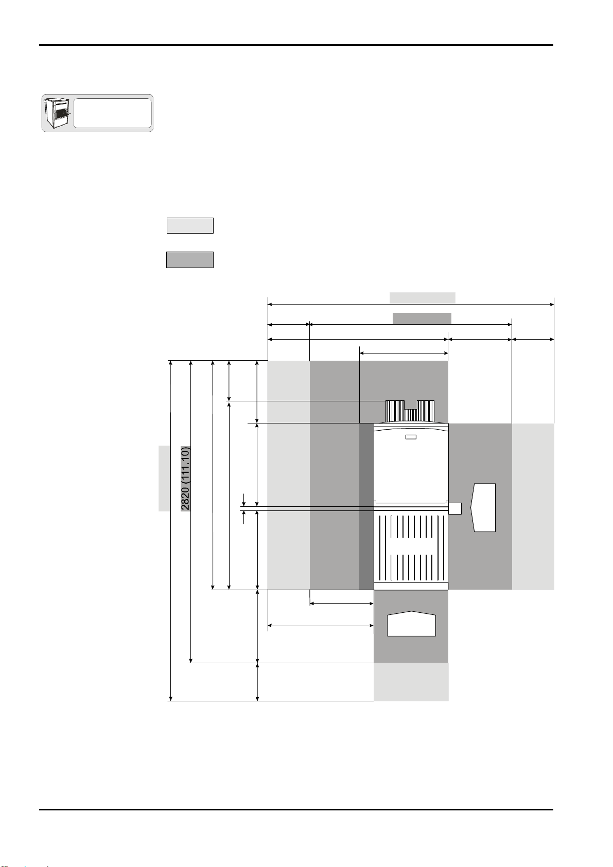
2.6.2 Classic E.O.S. CL Type 5270/105
The required floor space for the film processor in combination with the Laser
TYPE 5270/105
Imager LR3300 (with feed table, chute and the required clearance on the left)
is 1700 x 860 mm (66.98 x 33.88 inch). In case of an installation of the Laser
Imager LR3300 or another daylight system observe the installation
documentation enclosed with the machine.
The free space indicated in the illustration must be guaranteed for repair and
maintenance, otherwise the time required for service will increase.
Optimum dimensions:
We recommend to plan on this free space.
Minimum dimensions:
Do not go below this minimum space.
2710 (106.77)
3120 (122.92)
2120 (83.52)
380
1700 (66.98)
(14.97)
40 (1.57)
600
740 (29.15)
740 (29.15)
400
(15.76)
(23.64)
1710 (67.37)
600 (23.64)
1910 (75.25)
860 (33.88)
LR3300
600
(23.64)
(15.76)
A
5270_10001_005.cdr
400
700 (27.58)
300
1000 (39.4)
(11.82)
A
Figure 5
(A) Operation side
Dimensions in mm (inch)
Chapter 1 / 6 Classic E.O.S. / Classic E.O.S. CL Edition 6, Revision 0
(Type 5270 / 100 / 105) Agfa Group Confidential
Page 25

DD+DIS301.03E Installation Preparations
2.7 Unpacking
For unpacking follow the illustrated instructions attached to the outside of the
packing box and enclosed inside the box.
Required tools:
• Knife, scissors, or side cutting pliers to cut the straps
• Phillips screwdriver size 2
• Wrench size 10 mm
• Wrench size 13 mm
• Wrench size 17 mm
• Screwdriver 10 mm
• The forwarder will take back
the packing material and
dispose of it in compliance with
the local regulations.
527001vh.cdr
Figure 6
• Check the SHOCKWATCH
indicator (A) inside the
machine.
If the machine was subjected to
shocks, the square field in the
middle of the SHOCKWATCH
indicator (A) changed from white
to red.
A
PRODU
I
M
P
O
.
D
NC
ALL
I
,
AS,
TX.
OVERY
EC
R
F MEDIA
O
T
C
INDICATOR INDI KATOR
ROUGH HANDLING WILL CHANGE INDICATOR TO
BRIGHT RED. IF SHOCKWATCH IS RED NOTE
R
ON BILL OF LADING. INSPECTION MAY
T
E
D
B
Y
/
IM
P
O
R
T
I
E
R
U
.
S.
Model/Modell L- 65
R R
BE WARRENTED.
T
D
EX GMBH, FRANKFURT /
U
N
R
C
KO
H
P
A
T.
#
40
6
86
1
3
MAIN
5270_10001_006.cdr
Figure 7
Note all detected damage in the installation report!
In case of a damaged machine make sure to keep the packing material for
proof (transport insurance)! Send the damage report to the insurance
company.
Edition 6, Revision 0 Classic E.O.S. / Classic E.O.S. CL Chapter 1 / 7
Agfa Group Confidential (Type 5270 / 100 / 105)
Page 26
Installation Preparations DD+DIS301.03E
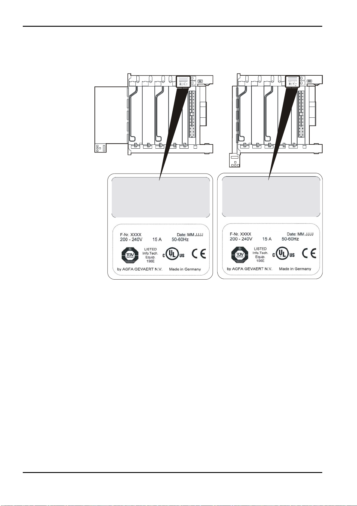
2.8 Checking the type label
Classic E.O.S. Type 5270/100 Classic E.O.S. CL Type 5270/105
This device complies with Part 15 of the FCC Rules.
Operation is subject to the following two conditions:
(1) this device may not cause harmful interference,
and (2) this device must accept any interference
received, inc lu ding int erfer ence that may cause
undesired operation.
527301zy.cdr
FUJIFILM FPM 3800AD
11.1999
1009
This device complies with Part 15 of the FCC Rules.
Operation is subject to the following two conditions:
(1) this device may not cause harmful interference,
and (2) this device must accept any interference
received, including interference that may cause
undesired operation.
Type 5270/100
This device complies with Part 15 of the FCC Rules.
Operation is subject to the following two conditions:
(1) this device may not cause harmful interference,
and (2) this device must accept any interference
received, inclu din g int er ference tha t may cause
undesired operation.
527301zy.cdr
FUJIFILM FPM 3800AD
1009
11.1999
This device complies with Part 15 of the FCC Rules.
Operation is subject to the following two conditions:
(1) this device may not cause harmful interference,
and (2) this device must accept any interference
received, including interference that may cause
undesired operation.
Typ e 5 273 /10 5
Type 5270/105
Explanation of the type label:
F-Nr. xxxx:
Date: MM.JJJJ:
V 200-240 15 A 50-60 HZ:
This is the consecutive serial number.
This is the production date (month/year).
Mains power supply
• Compare the information at "TYPE" and "F-Nr." on the type label with the
bill of lading.
• Compare the rated voltage with the power supply at the installation site.
2.9 Checking the accessory box
• Compare the contents of the accessory box with the list of contents
(included in the enclosed documentation pack).
5270_10001_001.cdr
Figure 8
Chapter 1 / 8 Classic E.O.S. / Classic E.O.S. CL Edition 6, Revision 0
(Type 5270 / 100 / 105) Agfa Group Confidential
Page 27
DD+DIS301.03E Installation Preparations
3 Technical Data
3.1 Electrical data
This is a summary of the technical data which serve to inspect the installation
site. For further technical, electrical, and climatic data and information
regarding the ambient conditions refer to Chapter 14.
Mains voltage connection
1N~ 230 - 240 V; 50/60 Hz (200 - 240 V)
Power consumption:
Standby
(room temperature ~ 20 °C)
During film processing
Fuse protection
Leakage current towards
ground
Main switch
Safety rules
0.45 kW/h (1620 kJ/h)
2.9 kW/h (10440 kJ/h)
max. 3.45 kW/h (12420 kJ/h)
15 A / 16 A
< 3.5 mA
Upon machine installation it must be
ensured that either the power plug or an
all-pole circuit breaker for the installation
on site is located close to the machine and
easily accessible.
Electrical installations in the installation
room must be in compliance with IEC 364
(VDE 0100 / 0107).
A GFI switch (I
with VDE 664) is integrated in the machine.
= 30 mA in compliance
N
3.2 Ambient and climatic conditions
Ventilation
Light-tightness
Acoustic test
ISO 7779 (airborne noise)
Edition 6, Revision 0 Classic E.O.S. / Classic E.O.S. CL Chapter 1 / 9
Agfa Group Confidential (Type 5270 / 100 / 105)
Avoid inhaling of chemical fumes. Make
sure that there is sufficient ventilation at the
installation site of the machine, i.e. an air
exchange that is at least ten times the
room volume per hour.
maximum 2500 Lux
during standby max. 35 dB (A)
during film cycle max. 48 dB (A)
Page 28
Installation Preparations DD+DIS301.03E
Heat emission
(all values are
approximate)
Standby (max.) into the room 250 W / 900 kJ/h
Room temperature
Relative humidity
Floor conditions
Floor load
Film cycle
(max.)
into the room 900 W / 3240 kJ/h
total 2100 W / 7560 kJ/h
Exhaust
connection
min. 10 °C (50 °F), max. 30 °C (86 °F)
Room temperature min. 5 °C (41 °F) below the set
developer temperature
min. 10 %, max. 80 %, no condensation
Waterproof, chemical-resistant floor covering
(pH value 4 - 11)
A floor drain close to the film processor is
recommended.
50 N / cm² (7.75 N / in²)
into the
connected
exhaust
The exhaust is a standard feature of
the dryer.
During film cycle the exhaust runs at
full power. During standby mode the
exhaust can be set to half-power via
the service program.
1200 W / 4320 kJ/h
Cleaning sink
A cleaning sink with water tap and hose shower should
be provided for maintenance work.
Minimum inside dimensions of the sink:
Width
Depth
Height
70 cm (27.56 inch)
40 cm (15.75 inch)
20 cm (7.87 inch)
Chapter 1 / 10 Classic E.O.S. / Classic E.O.S. CL Edition 6, Revision 0
(Type 5270 / 100 / 105) Agfa Group Confidential
Page 29
DD+DIS301.03E Installation Preparations
4 Dimensions and Weights
4.1 Classic E.O.S. Type 5270/100
TYPE 5270/100
Dimensions
incl. packing box 1200 (47.28) 800 (31.52) 1460 (57.52)
Length mm
(inch)
Width mm (inch) Height mm
(inch)
without packing
material
(with feed table
and chute)
Weight
with packing material 200 (441)
without packing material 135 (297)
with full tanks 165 (364)
1270 (50.03) 710 (27.97) 1130 (44.52)
4.2 Classic E.O.S. CL Type 5270/105
TYPE 5270/105
Dimensions
incl. packing box 1200 (47.28) 800 (31.52) 1460 (57.52)
Length mm
(inch)
Weight approx. kg (lbs)
Width mm (inch) Height mm
(inch)
without packing
material
(with docking unit
and chute)
Weight
with packing material 200 (441)
without packing material 135 (297)
with full tanks 165 (364)
Edition 6, Revision 0 Classic E.O.S. / Classic E.O.S. CL Chapter 1 / 11
Agfa Group Confidential (Type 5270 / 100 / 105)
1070 (42.15) 710 (27.97) 1130 (44.52)
Weight approx. kg (lbs)
Page 30
Installation Preparations DD+DIS301.03E
5 Machine Standards and Directives
5.1 Safety
Europe
EN 60950 / A11 1997 "Safety of Information Technology Equipment"
(identical with IEC 950: 1992 and VDE 0805/ 11. 97)
USA
UL 1950 3. July 1995 "Safety of Information Technology Equipment,
Including Electrical Business Equipment"
Canada
CSA 22.2 No. 950 - 95 "Safety of Information Technology Equipment,
Including Electrical Business Equipment”
5.2 Radio interference suppression
Europe
In compliance with EN 50081-1: 1992 "Generic Standard for Emission
Requirements", (identical with VDE 0839, Part 81-1/ 03. 93)
EN 55011 1998, Class B "Radio Disturbance Characteristics of Medical
Equipment" (corresponds to VDE 0878, Part 22 / 04.98)
For equipment in residential areas, business and commercial areas, and in
doctors’ offices.
North-America (USA, Canada)
US-Standard FCC 47 Part 15, Subchapter B, Class A / Edition 8/ 1976
Equipment considered “Non-Household Appliances”
5.3 Electromagnetic compatibility
EMVG and EG Regulation 89 / 336 / EEC
EN 50082-1: 1997
EN 61000-3-2 “Limit Values for Harmonic Emissions”
EN 61000-3-3 “Limit Values for Flicker”
Chapter 1 / 12 Classic E.O.S. / Classic E.O.S. CL Edition 6, Revision 0
(Type 5270 / 100 / 105) Agfa Group Confidential
Page 31

DD+DIS301.03E Installation Preparations
5.4 Certificates and guidelines
CE Medical Device Directive 93/42 EEC
TÜV Product Service Mark “Design tested and monitored”
UL Approbation E 477 50 (M)
C-UL Approbation E 477 50 (M)
"Technical directives for
drinking water installations,
protection against reflux”
General conditions and
administrative regulations for
minimum requirements on the
disposal of waste water into
public waters, dated
31.01.1994 (Germany)
Ministre de l’environment
(France)
DIN 1988, Part 4/ 1988 / EN 1717:2001
Appendix 53 – Photographic Processes
(silver halide photography)
Rubrique No. 2950
Maximum water consumption for
- single-layer emulsions must not exceed a
maximum of 15l/m
- double-sided emulsions must not exceed
a maximum of 30l/m
2
*
2
*
* activated in the program <Service Settings
/ Replenishment / Wat. Repl. Value>
Edition 6, Revision 0 Classic E.O.S. / Classic E.O.S. CL Chapter 1 / 13
Agfa Group Confidential (Type 5270 / 100 / 105)
Page 32

Page 33

Controls and Connections
2
Section 2
describes the controls and the connectors of the machine:
• Position and function of the controls
• Layout of the connectors and their modalities
Section 2
Page 34

Page 35

DD+DIS301.03E Controls and Connections
Chapter 2
Contents
1 Control panel ............................................................. 1
2 Switches.....................................................................2
2.1 Machine switches .................................................................... 2
2.2 Safety switches........................................................................3
3 Installation Connections........................................... 4
3.1 Installation through the front panel
(only for Classic E.O.S. Type 5270/100)................................. 4
3.2 Installation through the bottom..............................................5
3.2.1 Classic E.O.S. (5270/100)...................................................................5
3.2.2 Classic E.O.S. CL (5270/105).............................................................6
Edition 6, Revision 0 Classic E.O.S. / Classic E.O.S. CL Chapter 2 / I
Agfa Group Confidential (Type 5270 / 100 / 105)
Page 36

DD+DIS301.03E Controls and Connections
1 Control panel
Classic E.O.S. Type 5270/100 Classic E.O.S. CL Type 5270/105
(A) LCD
Display window consisting of 2 lines with 16 characters each.
Back key
Press this key to exit a dialog or a menu. If you press this key in an
input window any modifications made in this window will be canceled
and reset to the initial values.
Selection / Scroll keys
Use these keys to scroll through the options in the menus or to
change values in input windows.
Enter / Confirmation key
Use this key to show the options in a menu or to confirm a dialog. A
confirmed dialog opens the corresponding input window. Entered
data is confirmed and accepted.
A
5270_10002_003.cdr
Figure 1
Edition 6, Revision 0 Classic E.O.S. / Classic E.O.S. CL Chapter 2 / 1
Agfa Group Confidential (Type 5270 / 100 / 105)
Page 37

Controls and Connections DD+DIS301.03E
_
A
2 Switches
2.1 Machine switches
ST66
ST89
B
S1
ST53
IC52
C
Figure 2
(A) Main switch film processor
(B) Ground fault interrupter (GFI switch)
(C) Mains cable (VDE)
(D) Reset key PCB1
CM+952709450_ (F8.5270.7890._)
5270_10002
001.cdr
Chapter 2 / 2 Classic E.O.S. / Classic E.O.S. CL Edition 6, Revision 0
(Type 5270 / 100 / 105) Agfa Group Confidential
Page 38

DD+DIS301.03E Controls and Connections
2.2 Safety switches
A
B
5273_10002_006.CDR
Figure 3
(A) 0SW2 Safety switch for machine cover
(B) 0SW3 Safety switch for dryer
The machine has two safety switches, which interrupt the circuit when the
dryer is opened or the machine cover is removed.
Even with interrupted safety switches 0SW2 (A) and/or 0SW3 (B), and
the main switch 0SW1 in off position, there is still voltage applied on
the following components as long as the power cord is plugged in:
Ground fault interrupter 0FI
Mains switch 0SW1
Edition 6, Revision 0 Classic E.O.S. / Classic E.O.S. CL Chapter 2 / 3
Agfa Group Confidential (Type 5270 / 100 / 105)
Page 39

Controls and Connections DD+DIS301.03E
3 Installation Connections
3.1 Installation through the front panel (only for Classic E.O.S. Type 5270/100)
TYPE 5270/100
E
D
C
B
A
(A) Exhaust connection
5273_10002_004.cdr
Figure 4
F
G
H
(B) Developer overflow / drain (DEV)
(C) Fixer overflow / drain (FIX)
(D) Water overflow / drain (WAT)
(E) Tank safety overflow (OVERFLOW)
(F) Developer supply (DEV)
(G) Fixer 2 supply (FIX)
(H) Water supply (WAT)
Chapter 2 / 4 Classic E.O.S. / Classic E.O.S. CL Edition 6, Revision 0
(Type 5270 / 100 / 105) Agfa Group Confidential
Page 40

DD+DIS301.03E Controls and Connections
3.2 Installation through the bottom
3.2.1 Classic E.O.S. (5270/100)
TYPE 5270/100
FIX2 FIX1WAT DEV
EHF
D
(A) Exhaust connection
I
C
BA
G
5270_10002_002.cdr
Figure 5
(B) Developer overflow / drain (DEV)
(C) Fixer overflow / drain (FIX)
(D) Water overflow / drain (WAT)
(E) Tank safety overflow (OVERFLOW)
(F) Developer supply (DEV)
(G) Fixer 2 supply (FIX)
(H) Solenoid valve (and filter) water supply
(I) Solenoid valve water drain (anti-algae)
Edition 6, Revision 0 Classic E.O.S. / Classic E.O.S. CL Chapter 2 / 5
Agfa Group Confidential (Type 5270 / 100 / 105)
Page 41

Controls and Connections DD+DIS301.03E
3.2.2 Classic E.O.S. CL (5270/105)
TYPE 5270/105
FIX2 FIX1WAT DEV
DEHF
(A) Exhaust connection
I
BA
C
G
5270_10002_004.CDR
Figure 6
(B) Developer overflow / drain (DEV)
(C) Fixer overflow / drain (FIX)
(D) Water overflow / drain (WAT)
(E) Tank safety overflow (OVERFLOW)
(F) Developer supply (DEV)
(G) Fixer 2 supply (FIX)
(H) Solenoid valve (and filter) water supply
(I) Solenoid valve water drain (anti-algae)
Chapter 2 / 6 Classic E.O.S. / Classic E.O.S. CL Edition 6, Revision 0
(Type 5270 / 100 / 105) Agfa Group Confidential
Page 42

Page 43

Installation / Machine Start-up
3
Section 3
describes the exact routines necessary to start the machine operation.
Before putting the machine in operation you should be familiar with
the information of section 2 (controls and connectors).
Section 3
Page 44

Page 45

DD+DIS301.03E Installation and Startup
Chapter 3
Contents
1 Notes on the Installation and Startup
Procedures ................................................................ 1
2 Removal of Transport Protections .......................... 2
3 Installation ................................................................. 3
3.1 Height coarse adjustment.......................................................3
3.2 Height fine adjustment............................................................4
4 Power Cable Adaptation........................................... 5
5 Daylight / Darkroom Installation
(only Classic E.O.S. Type 5270/100) ........................ 6
5.1 Machine in the daylight, film feed in the darkroom,
light seal at the darkroom feed table .....................................6
5.1.1 Installation at the wall opening............................................................ 6
5.1.2 Installation with light tight wall.............................................................7
5.2 Machine in the darkroom, film exit in the daylight,
light seal at the dryer with light tight wall .............................8
5.2.1 Installation at the wall opening with light tight wall..............................8
5.2.2 Light tight wall ..................................................................................... 9
6 Supply and Disposal Connections ........................ 10
6.1 Installation diagram............................................................... 10
6.2 Overview of supply and disposal.........................................11
6.2.1 Classic E.O.S. (5270/100).................................................................11
6.2.2 Classic E.O.S. CL (5270/105)...........................................................12
6.3 Supply and disposal hoses .................................................. 13
6.3.1 Hoses inside the machine................................................................. 13
6.3.2 Hoses outside the machine............................................................... 13
6.4 Supply and disposal through the lower front panel
(only Classic E.O.S. Type 5270/100) ....................................14
6.4.1 Instructions for breaking out the openings ........................................ 14
6.4.2 Required openings for standard installations.................................... 14
6.4.3 Installing the exhaust connection...................................................... 15
6.4.4 Installing the developer / fixer supply hoses .....................................16
6.4.5 Installing the disposal hoses............................................................. 18
6.5 Supply and disposal through the floor................................19
6.5.1 Installing the exhaust connection...................................................... 19
6.5.2 Installing supply hoses...................................................................... 21
6.5.3 Installing the disposal hoses............................................................. 24
Edition 6, Revision 0 Classic E.O.S. / Classic E.O.S. CL Chapter 3 / I
Agfa Group Confidential (Type 5270 / 100 / 105)
Page 46

Installation and Startup DD+DIS301.03E
7 Connecting the Level Sensors...............................25
7.1 Replenisher tanks.................................................................. 25
7.1.1 Connect the level sensors of the replenisher tanks...........................25
7.1.2 Set the code for the replenisher tank level connection......................25
7.2 Mixer ....................................................................................... 26
7.2.1 Connecting the Mixer communication cable......................................26
7.2.2 Set the code of the mixer communication .........................................26
7.3 Disposal tanks ....................................................................... 27
7.3.1 Connect the level sensors of the disposal tanks ...............................27
7.3.2 Set the code for the disposal tank level sensors ...............................27
8 Adjusting Volume, Brightness, and Contrast
on the Control Board PCB1.................................... 28
9 Starting Operation...................................................29
9.1 Preparing the startup procedure.......................................... 29
9.2 Adapting the mains supply................................................... 29
9.3 Checking the function of the GFI switch 0FI.......................30
9.4 Filling the developer and fixer tanks ...................................31
9.4.1 Manual filling (in Type 5270/100 and Type 5270/105) ......................31
9.4.2 Automatic filling with the AUTOFILL function
(only in Type 5270/105).....................................................................32
9.5 Switching on the machine .................................................... 32
9.6 Calibrating the replenishment rate of
developer and fixer upon first startup ................................. 33
9.7 Reset after switching on the machine ................................. 37
9.8 BASEINIT................................................................................ 38
9.8.1 Only execute a BASEINIT in case of:................................................38
9.8.2 Initiate a BASEINIT:...........................................................................38
9.9 System settings..................................................................... 39
9.9.1 Setting the software switches in the SERVICE program...................39
9.9.2 Setting the process parameters on the control panel ........................39
9.9.3 Access to the SERVICE program......................................................41
9.9.4 Setting date and time.........................................................................41
9.9.5 Setting the service intervals in the SERVICE program......................42
9.9.6 Executing a <Teach In> in the SERVICE program ........................43
9.9.7 Calibrating the Developer Temperature (CAL)..................................45
9.9.8 Resetting the temporary infocounters
in the SERVICE program...................................................................46
9.9.9 Display all <Service Settings>
in the SERVICE program with <Quick Display>.........................47
9.9.10 Setting the customer specific settings
in the SERVICE program <Service Settings>..........................48
9.9.11 DEFAULT settings ex factory / after BASEINIT.................................56
9.9.12 Processes..........................................................................................56
9.9.13 Process data......................................................................................57
9.9.14 Application dependent process parameter........................................57
Chapter 3 / II Classic E.O.S. / Classic E.O.S. CL Edition 6, Revision 0
(Type 5270 / 100 / 105) Agfa Group Confidential
Page 47

DD+DIS301.03E Installation and Startup
1 Notes on the Installation and Startup Procedures
The manufacturer tested this machine with chemicals and film material.
Therefore any possible traces of chemicals do not indicate a used machine
but they are the proof of a function-tested and perfect machine.
The sequence of listed installation steps depends on the following parameters:
• Size of the installation room
• Type of installation:
Daylight / darkroom installation
Light seal feed table / dryer directly against installation wall or light-tight
wall
• Supply / disposal connections through the lower front panel or below the
machine
• Machine standing free in the room or with the left hand machine side at a
distance from the wall of at least 15 cm (5.91 inch)
Please go through these procedures and arrange a sequence required for
your installation.
The sequence described below corresponds to a standard installation with the
following parameters:
• Film feed in the darkroom, machine in the daylight
Light seal at the film feed table without / with light tight wall
• Film feed / machine in the darkroom, film exit in the daylight
Light seal with light-tight wall behind the dryer / film exit
• Installation connections through the lower front panel (below the film feed
table)
• Installation connections through the floor
• Machine with the left hand machine side at a distance from the wall of at
least 15 cm (5.91 inch)
Edition 6, Revision 0 Classic E.O.S. / Classic E.O.S. CL Chapter 3 / 1
Agfa Group Confidential (Type 5270 / 100 / 105)
Page 48

Installation and Startup DD+DIS301.03E
2 Removal of Transport Protections
(1) Undo 2 screws on the dryer
panels and remove the dryer
panels, open the dryer flap.
(2) Remove the transport protection
from the dryer.
(3) Remove the transport protection
from the film transport flap (only in
Type 5270/105).
1
2
3
(4) Close the dryer flap and dryer
panels, tighten the screws of the
dryer panels.
B
4
5270_10003_016.cdr
15 cm (5.91 inch)
Figure 1
A
5270_10003_001 .cdr
Figure 2
(A) Lock nuts
(B) Film transport direction
• If a machine is installed with the left hand side only 15 cm (5.91 inch) from
the wall, the lock nuts (A) must be removed during installation to make the
maintenance easier.
Chapter 3 / 2 Classic E.O.S. / Classic E.O.S. CL Edition 6, Revision 0
(Type 5270 / 100 / 105) Agfa Group Confidential
Page 49

DD+DIS301.03E Installation and Startup
A
3 Installation
Wrench (Ø 17 mm)
3.1 Height coarse adjustment
TYPE 5270/100
• Slacken the lock nuts (A).
• Adjust the hex nuts (B) to a
height of 30 mm (1.18 inch).
Clockwise = higher
Counterclockwise = lower
• Adjust the height of the
adjustable machine feet to level
the machine.
30 mm
1.18 inch
Figure 3
Edition 6, Revision 0 Classic E.O.S. / Classic E.O.S. CL Chapter 3 / 3
Agfa Group Confidential (Type 5270 / 100 / 105)
Page 50

Installation and Startup DD+DIS301.03E
3.2 Height fine adjustment
The fine adjustment should only be made when the machine is at its final
installation site.
A poorly adjusted machine installation may result in film processing errors!
Measure in film transport
direction:
• Remove the machine cover.
• Remove the crossovers above
the racks.
• Place a spirit level (A) on the
upper tie rod of the fixer rack (3)
and the water rack (4). Adjust
the height of the rear and front
feet until the machine is level in
transport direction.
Measure across film transport
direction:
• Place a second spirit level (B)
on the upper tie rods of the
developer rack (1) and then on
the tie rods of the water rack (4).
• Adjust the foot height left and
right.
• Readjust the height of the rear
and front feet.
• Check the adjustment in and
across the film transport
direction, and readjust if
necessary.
(A/B)
(C)
(1)
(2)
(3)
(4)
2
3
4
Spirit level
Film transport direction
Developer rack
Fixer rack1
Fixer rack2
Water rack
2
3
4
Figure 4
A
1
1
5273_10003_007.cdr
B
C
Chapter 3 / 4 Classic E.O.S. / Classic E.O.S. CL Edition 6, Revision 0
(Type 5270 / 100 / 105) Agfa Group Confidential
Page 51

DD+DIS301.03E Installation and Startup
A
4 Power Cable Adaptation
Ex-factory the machine configuration includes a VDE cable.
If there are only UL/CSA connections available the VDE power cable must be
replaced by the UL/CSA cable enclosed in the accessory box.
The power cable must only be exchanged when the film processor has
no power supply. The installed power cable must not be plugged into an
outlet!
B
C
Figure 5
• Replace the VDE power cable by the UL/CSA cable.
Make sure• to tighten clamping screw (A) if plug (B) is connected in
outlet (C).
Edition 6, Revision 0 Classic E.O.S. / Classic E.O.S. CL Chapter 3 / 5
Agfa Group Confidential (Type 5270 / 100 / 105)
Page 52

Installation and Startup DD+DIS301.03E
5 Daylight / Darkroom Installation
(only Classic E.O.S. Type 5270/100)
For installation of the Classic E.O.S CL Type 5270/105 please refer to the
installation instructions in Chapter 9: Accessories and Options.
5.1 Machine in the daylight, film feed in the darkroom, light seal at the darkroom feed table
5.1.1 Installation at the wall opening
Darkroom Daylight
4
6
3
1
2
TYPE 5270/100
Film feed
Film output (wire chute)
A 60° chamfer must be provided
on the wall opening
Wall
Wall base
Light seal
(foam rubber – by the meter)
Order no. CM+0000014259
Wall opening:
Wall
Wall base
Wall opening
5
min. 1120 (44.1)
50 (1.97)
Figure 6
Dimensions in mm (inch)
min. 580 (22.8)
max. 680 (26.8)
3
max. 1120 (44.1)
2
50 (1.97)
Figure 7
527214nm.cdr
1
527014jm.cdr
Dimensions in mm (inch)
Chapter 3 / 6 Classic E.O.S. / Classic E.O.S. CL Edition 6, Revision 0
(Type 5270 / 100 / 105) Agfa Group Confidential
Page 53

DD+DIS301.03E Installation and Startup
5.1.2 Installation with light tight wall
Darkroom Daylight
3
2
4
TYPE 5270/100
Film feed
A 60° chamfer must be provided
on the wall opening.
Wall
Light tight wall
Film output (wire chute)
1
Wall base
Light seal
(foam rubber – by the meter)
Order no. CM+0000014259
min. 1120 (44.1)
max. 1500 (59.1)
7
6
5
Wall opening
Wall
Wall overlap
Wooden board, 20 mm
(0.79 inch), with opening
Figure 8
Dimensions in mm (inch)
3
1550 (61.0)
min. 1110 (43.7)
max. 1120 (44.1)
50 (1.97)
min. 670 (26.4)
max. 680 (26.8)
527014pm.cdr
2
2
1
1
527014lm.cdr
Figure 9
Dimensions in mm (inch)
See Chapter 3, Section 5.2.2 Light tight wall
Edition 6, Revision 0 Classic E.O.S. / Classic E.O.S. CL Chapter 3 / 7
Agfa Group Confidential (Type 5270 / 100 / 105)
Page 54

Installation and Startup DD+DIS301.03E
5.2 Machine in the darkroom, film exit in the daylight, light seal at the dryer with light tight wall
5.2.1 Installation at the wall opening with light tight wall
Darkroom Daylight
2
3
1
6
7
527014rm.cdr
min. 1120 (44.1)
max. 1500 (59.1)
TYPE 5270/100
Film feed
Wall
A 60° chamfer must be provided
on the wall opening.
Light tight wall
Film output (wire chute)
Light seal
(foam rubber – by the meter)
Order no. CM+0000014259
Wall base
Wall opening
Wall
Wall overlap / light tight wall
overlapping by at least 50 mm
(1.97 inch) on all sides
Wooden board, 20 mm
(0.79 inch), with opening
Figure 10
Dimensions in mm (inch)
3
1550 (61.0)
min. 1110 (43.7)
max. 1120 (44.1)
50 (1.97)
min. 670 (26.4)
max. 680 (26.8)
Figure 11
2
2
1
1
527014lm.cdr
Dimensions in mm (inch)
See Chapter 3, Section 5.2.2 Light tight wall
Chapter 3 / 8 Classic E.O.S. / Classic E.O.S. CL Edition 6, Revision 0
(Type 5270 / 100 / 105) Agfa Group Confidential
Page 55

DD+DIS301.03E Installation and Startup
5.2.2 Light tight wall
TYPE 5270/100
5273_10003_004.cdr
min. 1110 (43.7)
max. 1120 (44.1)
min. 670 (26.4)
max. 680 (26.8)
1020 (40.2)
Figure 12
Coverage of a wall opening of up to 1500 mm x 920 mm
(57.09 inch x 36.22 inch) is possible.
An overlap of 50 mm (1.97 inch) must be guaranteed on all sides.
The manufacturer does not supply the light tight wall (wooden board) required
for the installation of a film processor!
Dimensions in mm (inch)
Edition 6, Revision 0 Classic E.O.S. / Classic E.O.S. CL Chapter 3 / 9
Agfa Group Confidential (Type 5270 / 100 / 105)
Page 56

Installation and Startup DD+DIS301.03E
6 Supply and Disposal Connections
6.1 Installation diagram
8
E
D
WAT
FIX 1FIX 2
DEV
7
5
DEV
FIX
B
C
4
6
G
2
F
3
H
1
FIX
Figure 13
(D) Water overflow / drain (WAT) (1) Mixer
(E) Tank safety overflow (OVERFLOW) (2) Fixer replenishment pump
(C) Fixer overflow / drain (FIX) (4) Solenoid valve water drain
(B) Developer overflow / drain (DEV) (5) Individual disposal tanks or
(G) Fixer 2 supply (FIX) (6) Solenoid water supply (anti-
(F) Developer supply (DEV) (7) Overflow tray
(H) Water supply (WAT) (8) Film transport direction
The connections of supply and disposal hoses may be at the bottom (through
the floor) or in the front (through the front panel – only for Type 5270/100).
DEV
(3) Developer replenishment
pump
centralized disposal
algae)
5273_100003_018.cdr
Chapter 3 / 10 Classic E.O.S. / Classic E.O.S. CL Edition 6, Revision 0
(Type 5270 / 100 / 105) Agfa Group Confidential
Page 57

DD+DIS301.03E Installation and Startup
6.2 Overview of supply and disposal
6.2.1 Classic E.O.S. (5270/100)
TYPE 5270/100
FIX2 FIX1WAT DEV
I
EHF
C
D
BA
Figure 14
(A) Exhaust connection
(B) Developer overflow / drain (DEV)
G
5273_10002_005.CDR
(C) Fixer overflow / drain (FIX)
(D) Water overflow / drain (WAT)
(E) Tank safety overflow (OVERFLOW)
(F) Developer supply (DEV)
(G) Fixer 2 supply (FIX)
(H) Solenoid valve (and filter) water drain (WAT)
(I) Solenoid water supply (anti-algae)
Edition 6, Revision 0 Classic E.O.S. / Classic E.O.S. CL Chapter 3 / 11
Agfa Group Confidential (Type 5270 / 100 / 105)
Page 58

Installation and Startup DD+DIS301.03E
6.2.2 Classic E.O.S. CL (5270/105)
TYPE 5270/105
FIX2 FIX1WAT DEV
I
DEHF
BA
C
Figure 15
G
5270_10002_004.CDR
(A) Exhaust connection
(B) Developer overflow / drain (DEV)
(C) Fixer overflow / drain (FIX)
(D) Water overflow / drain (WAT)
(E) Tank safety overflow (OVERFLOW)
(F) Developer supply (DEV)
(G) Fixer 2 supply (FIX)
(H) Solenoid valve (and filter) water drain (WAT)
(I) Solenoid water supply (anti-algae)
Chapter 3 / 12 Classic E.O.S. / Classic E.O.S. CL Edition 6, Revision 0
(Type 5270 / 100 / 105) Agfa Group Confidential
Page 59

DD+DIS301.03E Installation and Startup
6.3 Supply and disposal hoses
6.3.1 Hoses inside the machine
Internal hoses are pre-installed.
The supply and disposal hoses for developer, fixer, water, and safety overflow
in the machine are marked by tapes:
DEV WAT
FIX
Tapes to be wrapped around external hoses are included in the accessory
box.
6.3.2 Hoses outside the machine
External hoses can be ordered by the meter.
For the installation of external hoses only use fiber-reinforced hoses!
The following hoses are to be used for the supply connections:
Supply
connection
Developer red (DEV) 10x3 / 0.39x0.12
Fixer blue (FIX) 10x3 / 0.39x0.12
The following hoses are to be used for the disposal connections:
Disposal
connection
Developer red (DEV) 19x4 / 0.75x0.16
Fixer blue (FIX) 19x4 / 0.75x0.16
Water transparent
safety overflow fiber-reinforced
The accessory box includes an approx. 50 cm (19.69 inch) long PAP hose for
the exhaust connection.
The PAP hose (Ø 100 mm / Ø 3.94 inch) can be ordered by the meter:
Order number CM+0000064117
= developer = water
= fixer
Color Dimensions Order number
Color Dimensions Order number
(WAT)
OVERFLOW
(mm / inch)
fiber-reinforced
fiber-reinforced
(mm / inch)
fiber-reinforced
fiber-reinforced
19x4 / 0.75x0.16
= safety overflow
CM+0000064082
CM+0000064083
CM+0000064133
CM+0000064134
CM+0000007620
Edition 6, Revision 0 Classic E.O.S. / Classic E.O.S. CL Chapter 3 / 13
Agfa Group Confidential (Type 5270 / 100 / 105)
Page 60

Installation and Startup DD+DIS301.03E
6.4 Supply and disposal through the lower front panel (only Classic E.O.S. Type 5270/100)
6.4.1 Instructions for breaking out the openings
It is not necessary to remove the
TYPE 5270/100
6.4.2 Required openings for standard installations
TYPE 5270/100
front panel in order to break out
the openings.
• Mark the recesses to be
broken out with a felt-tip
marker.
• The recessed material can be
broken out with a screwdriver
applied in the groove at the
outside and a blow with the
hammer.
(A) Exhaust connection
(B) Developer overflow / drain
(C) Fixer overflow / drain
Figure 16
(D) Water overflow / drain
(E) Safety overflow, tanks
(F) Developer supply
(G) Fixer 2 supply
(H) Water supply
E
D
B
C
A
Figure 17
G
H
5273_10002_004.cdr
F
Chapter 3 / 14 Classic E.O.S. / Classic E.O.S. CL Edition 6, Revision 0
(Type 5270 / 100 / 105) Agfa Group Confidential
Page 61

DD+DIS301.03E Installation and Startup
6.4.3 Installing the exhaust connection
TYPE 5270/100
The machine internal exhaust must always be guided out of the machine.
- The film processor has an integrated exhaust duct (A).
Crossover (B) and the flexible exhaust hose (C) (∅ 100 mm / 3.94 inch)
are pre-mounted and included in the accessory box.
- Exhaust connection: ∅ 100 mm (3.94 inch)
- Max. length of the exhaust hose: 5 m (196.85 inch) (if this length is
exceeded install an additional fan!)
- Exhaust min. 50 m³/h
volume: max. 100 m³/h
A
G
E
B
C
(A)
Exhaust duct
(B)
Crossover
(C)
Flexible exhaust hose inside
(D)
Exhaust connection stub
(E)
Frame
• Break out the recess for the exhaust connection (Figure 17).
• Screw the exhaust connection stub (D) to the front panel using the
3 Phillips screws included in the accessory box.
• Loosen the mounting screw (G) located between the exhaust duct (A) and
frame (E).
• Push the crossover section (B) onto the exhaust duct.
• Mount both ducts on the frame with mounting screw (G).
• Push the exhaust hose (C) onto the exhaust connection stub (D)
integrated inside the front panel.
D
Figure 18
(F)
(G)
5273_10003_022.CDR
Exhaust duct to the room
exhaust (PAP hose)
Mounting screw for crossover
(B)
F
• Push exhaust hose (F) on the exhaust connection stub (D) and connect it
to the room exhaust.
Edition 6, Revision 0 Classic E.O.S. / Classic E.O.S. CL Chapter 3 / 15
Agfa Group Confidential (Type 5270 / 100 / 105)
Page 62

Installation and Startup DD+DIS301.03E
6.4.4 Installing the developer / fixer supply hoses
TYPE 5270/100
Only use fiber-reinforced PVC hoses Ø 10x3 mm (0.39x0.12 inch) for the
external hose connections (outside the machine)!
Position the hoses without kinks!
Installing the developer / fixer supply:
2
1
3
4
5
7
6
7
G
8
10
9
F
A
527003OM.CDR
Figure 19
(F) Developer (DEV) (A) Supply direction
(G) Fixer (FIX)
POS Designation Configuration
1 PVC hose
Ø 9x1.5 mm (0.35x0.06 inch)
2 Hose positioning /
reinforcement bend-protection
3 Hose clamp
4 Hose connection stub
5 Threaded bush Included in the accessory box
6 Rubber elbow
Ø 10 mm (0.39 inch)
7 Hose clamp Not included in shipment, can be
8 Pipe stub
Ø 10x1 mm (0.39x0.04 inch)
9 PVC hose
Ø 10x3 mm (0.39x0.12 inch)
fiber-reinforced
Developer: red,
Fixer: blue
10 Hose clamp Not included in shipment, can be
Pre-installed in the machine
Not included in shipment, can be
ordered, CM+7946064580
Pre-installed in the machine
Not included in shipment, can be
ordered, CM+9511017970
ordered, CM+7037200210
Not included in shipment, can be
ordered, CM+9511017920
Not included in the shipment, can
be ordered,
CM+0000064082
CM+0000064083
ordered, CM+9037200230
Chapter 3 / 16 Classic E.O.S. / Classic E.O.S. CL Edition 6, Revision 0
(Type 5270 / 100 / 105) Agfa Group Confidential
Page 63

DD+DIS301.03E Installation and Startup
Install the water pressure hose:
TYPE 5270/100
For installation of the water pressure hose refer also to
Chapter 14.
H
Figure 20
POS Designation Configuration
1 Safety pressure hose Pre-installed
2 Rubber hose passage / light seal Included in the
accessory box
• Position the water pressure hose through the front panel (H).
• Connect the union nut (A) on the
water pressure hose together with
the dirt filter (B).
• Tighten the union nut (A) with a
pipe wrench (tightness!).
1
2
527003PM.CDR
• Connect the safety pressure hose
with the water supply.
B
A
5273_10003_005.cdr
Figure 21
If a pressure reducer is included in the installation, set the
pressure to 2-6 bar.
Edition 6, Revision 0 Classic E.O.S. / Classic E.O.S. CL Chapter 3 / 17
Agfa Group Confidential (Type 5270 / 100 / 105)
Page 64

Installation and Startup DD+DIS301.03E
6.4.5 Installing the disposal hoses
TYPE 5270/100
Only use fiber-reinforced PVC hoses Ø 19x4 mm (0.75x0.16 inch) for the
external hose connections (outside the machine)!
Position the hoses without kinks!
A
2
1
3
4
5
6
5
7
5
8
Figure 22
(A) Drain direction (D) Water drain / overflow
(B) Developer drain / overflow (E) Safety overflow, tanks
(C) Fixer drain / overflow
Pos Designation Configuration
1 PVC hose Ø 19x2.5 mm
(0.75x0.10 inch) transparent
2 Hose clamp
3 Hose connection stub
Ø 20 mm (0.79 inch)
4 Threaded bush Included in the accessory box
5 Hose clamp Not included in shipment, can
6 Rubber elbow Not included in shipment, can
7 Pipe stub
Ø 20 mm (0.79 inch)
8 PVC hose, Not included in shipment,
Developer (red, fiber-reinforced):
Ø 19x4 mm (0.75x0.16 inch)
Fixer (blue, fiber-reinforced):
Ø 19x4 mm (0.75x0.16 inch)
Water (transparent, fiber-reinforced):
Ø 19x4 mm (0.75x0.16 inch) CM+0000007620
• Combine the hoses of the safety overflow (OVERFLOW) and water (WAT)
with a Y piece and connect them with one drain hose, if this is permitted by
the local regulations. Install the drain hose to the floor drain.
Pre-installed in the machine
be ordered, CM+9037200400
be ordered, CM+9889629521
Not included in shipment, can
be ordered, CM+7839185010
can be ordered
CM+0000064133
CM+0000064134
B
527003QM.CDR
D
E
Chapter 3 / 18 Classic E.O.S. / Classic E.O.S. CL Edition 6, Revision 0
(Type 5270 / 100 / 105) Agfa Group Confidential
Page 65

DD+DIS301.03E Installation and Startup
6.5 Supply and disposal through the floor
6.5.1 Installing the exhaust connection
The machine internal exhaust must always be guided out of the machine.
• The film processor has an integrated exhaust duct (A).
Crossover (B) and the flexible exhaust hose (C) (∅ 100 mm / 3.94 inch)
are pre-mounted and included in the accessory box.
• Exhaust connection: ∅ 100 mm (3.94 inch)
• Max. length of the exhaust hose: 5 m (196.85 inch) (if this length is
exceeded install an additional fan!)
• Exhaust
volume:
min. 50 m³/h
max. 100 m³/h
(A) Exhaust duct
(B) Crossover
(C) Flexible exhaust hose inside
(D) On-site exhaust pipe
(F) Exhaust connection stub
A
B
C
(G) Hose clamp
(H) Floor
(core hole for exhaust
connection:
∅ ≥ 114 mm (4.49 inch))
max. 5 m
max. 196.9 inch
D
Figure 23
G
F
H
527003KM.CDR
Edition 6, Revision 0 Classic E.O.S. / Classic E.O.S. CL Chapter 3 / 19
Agfa Group Confidential (Type 5270 / 100 / 105)
Page 66

Installation and Startup DD+DIS301.03E
A
E
S
B
C
Figure 24
• Loosen the mounting screw (S).
• Push the crossover section (B) onto the exhaust duct (A).
• Tighten the mounting screw (S).
• Frame (E)
• Connect the exhaust hose (C) on
the exhaust stub (F) and fix with a
hose clamp (G).
• Connect the on-site exhaust pipe
(D) on the exhaust stub (F) and fix
with a hose clamp (G).
• Tighten the screw connection of
the two exhaust stubs (F).
527003CJ.CDR
Figure 25
This installation requires an additional exhaust stub Ø 100 (F)
CM+9522030091
Chapter 3 / 20 Classic E.O.S. / Classic E.O.S. CL Edition 6, Revision 0
(Type 5270 / 100 / 105) Agfa Group Confidential
Page 67

DD+DIS301.03E Installation and Startup
6.5.2 Installing supply hoses
Only use fiber-reinforced PVC hoses Ø 10x3 mm (0.39x0.12 inch) for the
external hose connections (outside the machine)!
Position the hoses without kinks!
Classic E.O.S. (5270/100)
Classic E.O.S. CL (5270/105)
TYPE 5270/100
1
H
4
9
Figure 26
TYPE 5270/105
1
3
4
10
9
5270_10003_016.CDR
H
1
3
4
10
9
Figure 27
5270_10014_011.CDR
POS Designation Configuration
1 PVC hose
Pre-installed in the machine
Ø 9x1.5 mm (0.35x0.06 inch)
3 Hose clamp
4 Hose connection stub
10 Hose clamp Not included in shipment, can be
ordered, CM+9037200230
9 PVC hose
Ø 10x3 mm (0.39x0.12 inch)
fiber-reinforced
Developer: red
Fixer: blue
Not included in the shipment, can
be ordered,
CM+0000064082
CM+0000064083
H Safety pressure hose Pre-installed
Edition 6, Revision 0 Classic E.O.S. / Classic E.O.S. CL Chapter 3 / 21
Agfa Group Confidential (Type 5270 / 100 / 105)
Page 68

Installation and Startup DD+DIS301.03E
• If necessary shorten the internal supply hoses and insert the hose
connection again.
• Connect the fiber-reinforced (external) PVC hoses with the hose
connection of the internal supply hoses.
• Position the hoses together through the opening in the bottom to the mixer
or to the individual tanks.
Chapter 3 / 22 Classic E.O.S. / Classic E.O.S. CL Edition 6, Revision 0
(Type 5270 / 100 / 105) Agfa Group Confidential
Page 69

DD+DIS301.03E Installation and Startup
Install the water pressure hose
For installation of the water safety pressure hose refer also to
Chapter 14, Section 8.
• Connect the union nut (A) on the
safety pressure hose together with
the dirt filter (B).
• Tighten the union nut (A) with a
pipe wrench (tightness!).
• Connect the safety pressure hose
with the water supply.
If a pressure reducer is included in the installation, set the pressure
to 2-6 bar.
B
A
5273_10003_005.cdr
Figure 28
Edition 6, Revision 0 Classic E.O.S. / Classic E.O.S. CL Chapter 3 / 23
Agfa Group Confidential (Type 5270 / 100 / 105)
Page 70

Installation and Startup DD+DIS301.03E
6.5.3 Installing the disposal hoses
FIX2 FIX1 DEVWAT
1
2
3
5
8
5270_10003_017.CDR
Figure 29
Pos Designation Configuration
1 PVC hose Ø 19x2.5 mm
(0.75x0.10 inch) transparent
Pre-installed in the machine
2 Hose clamp
3 Hose connection stub
Ø 20 mm (0.79 inch)
5 Hose clamp Not included in the shipment,
CM+9037200400
8 PVC hose, Not included in shipment,
Developer (red, fiber-reinforced):
Ø 19x4 mm (0.75x0.16 inch)
Fixer (blue, fiber-reinforced):
Ø 19x4 mm (0.75x0.16 inch)
Water (transparent, fiber-reinforced):
Ø 19x4 mm (0.75x0.16 inch)
can be ordered
CM+0000064133
CM+0000064134
CM+0000007620
• Shorten the internal disposal hoses if necessary and insert the hose
connection stub (3) again.
• Connect the fiber-reinforced (external) PVC hoses with the hose connection
stub (3) of the internal disposal hoses.
• Position the developer / fixer disposal hoses together through the opening
in the bottom to the central disposal site.
• Combine the hoses of the safety overflow (OVERFLOW) and water (WAT)
with a Y piece and connect them with one drain hose, if this is permitted by
the local regulations. Install the drain hose to the floor drain.
Chapter 3 / 24 Classic E.O.S. / Classic E.O.S. CL Edition 6, Revision 0
(Type 5270 / 100 / 105) Agfa Group Confidential
Page 71

DD+DIS301.03E Installation and Startup
7 Connecting the Level Sensors
7.1 Replenisher tanks
SI9
ST55
S1
ST15
Film Out
ST66
ST53
ST87
MC29
MC28
MC27
ST89
ST82
ST90
R464
IC51
ST57
C210
SI2
ST62
ST54
ST64
ST65
IC63
ST88
IC78
IC79
IC57
ST63
ST85
IC52
IC50
ST81
R465
IC88
Contrast
Brightness
ST67 ST68 ST69
ST71
ST76
ST74
ST75
MC2
MC20
ST73ST72
ST79
ST77ST78
MC31
MC13
MC34
ST70
MC32
BU9
ST45
MC22
ST4
ST88
RS4 RS1 RS 3
RS2
RS9
L11
MC4
C80
ST68 ST69
C64
C63
MC3
C79
ST71
ST74 ST79
RS6 RS7RS5
ST86
ST76
MC16
MC17
ST73ST72
RS8
ST77ST78
CM+952709450_ (F8.5270.7890._)
Figure 30
7.1.1 Connect the level sensors of the replenisher tanks
TY2
TY1
MC35
MC36
RS24
R485
R475
SI10
SI11 SI6 SI7
BU10
+12MOT
HeatF
R476
R380
SI12
R377
RS22
R378
BU7
5273_10003_009.cdr
SI8
ST5
MC24
MC23
B
U
4
IR
Blowe
RS19
RS21
RS20
R379
SI1
RS23
R381
SI3SI5
BU6
XK1
• Connect the level sensors of the replenisher tanks on the Control Board
PCB1 as follows:
Developer supply
Fixer supply
Anti-algae level
ST 71
ST 72
ST 79
7.1.2 Set the code for the replenisher tank level connection
• Call up the SERVICE program.
• In the dialog window <Dev/Fix Repl Tnk conn.?> or
<Algicide Tank conn.?> enter
<YES>.
Any
Display
Settings
Language
Service
InfoCounters
Test & Adjust
Service Settings
Replenishment
DevFix SuppCond
Dev/Fix Repl Tnk
conn.? YES NO
5
Algcid SuppCond
5273_10003_023.cdr
Algicide Tank
conn.? YES NO
Figure 31
Edition 6, Revision 0 Classic E.O.S. / Classic E.O.S. CL Chapter 3 / 25
Agfa Group Confidential (Type 5270 / 100 / 105)
Page 72

Installation and Startup DD+DIS301.03E
7.2 Mixer
SI9
ST55
S1
ST15
Film Out
ST66
ST53
ST87
MC29
MC28
MC27
ST89
ST82
ST90
R464
IC57
C210
MC28
ST63
ST57
ST85
IC52
ST66
IC51
IC50
ST81
R465
IC88
Contrast
Brightness
IC63
ST89
MC27
SI2
ST54
ST64
IC78
ST9
ST62
ST65
ST88
IC79
ST67 ST68ST69
ST71
ST74
ST75
ST76
MC13
MC2
MC20
MC34
ST73ST72
ST79
ST77ST78
MC31
ST70
MC32
BU9
ST45
MC22
ST4
RS4 RS1 RS 3
RS2
RS9
MC4
MC3
RS6 RS7RS5
CM+952709450_ (F8.5270.7890._)
Figure 32
7.2.1 Connecting the Mixer communication cable
L11
ST86
MC16
MC17
C80
C79
TY2
C64
C63
TY1
+12MOT
HeatF
R476
R380
SI12
MC35
R485
R475
RS8
SI11 SI6 SI7
BU10
MC36
RS24
SI10
R377
RS22
R378
BU7
5273_10003_010.cdr
SI8
ST5
MC24
MC23
B
U
4
IR
Blowe
RS19
RS21
RS20
R379
SI1
RS23
R381
SI3SI5
BU6
XK1
• Plug the communication cable of the Chemix Mixer (20 m / 787.4 inch
long), CM+9528030301, into the Control Board PCB1 / ST66.
7.2.2 Set the code of the mixer communication
• Call up the SERVICE program.
• In the dialog window <Mixer conn.?> enter
Any
Display
Settings
Language
Service
5
InfoCounters
Test & Adjust
Service Settings
Replenishment
Mixer Cond
Figure 33
<YES>.
Mixer
conn.? YES NO
5273_10003_024.cdr
Chapter 3 / 26 Classic E.O.S. / Classic E.O.S. CL Edition 6, Revision 0
(Type 5270 / 100 / 105) Agfa Group Confidential
Page 73

DD+DIS301.03E Installation and Startup
7.3 Disposal tanks
ST55
ST15
Film Out
IC57
MC29
MC28
MC27
ST89
ST90
ST66
S1
ST53
ST82
R464
ST87
ST63
ST85
IC52
IC50
ST81
R465
IC88
Contrast
Brightness
IC51
ST57
IC63
C210
ST54
ST64
MC31
MC32
BU9
SI2
ST62
ST65
ST67 ST68 ST69
ST88
IC78
IC79
ST73ST72
ST71
ST76
ST79
ST74
ST77ST78
ST75
MC13
MC2
MC20
MC34
ST70
ST45
MC22
ST4
RS4 RS1 RS 3
L11
MC4
C80
C64
C63
MC3
C79
ST71
ST88
ST74 ST79
RS6 RS 7RS5
RS2
RS9
ST86
CM+952709450_ (F8.5270.7890._)
Figure 34
7.3.1 Connect the level sensors of the disposal tanks
MC16
MC17
TY2
ST68 ST69
TY1
ST73ST72
MC35
MC36
ST76
R485
R475
RS8
SI11 SI6 SI7
ST77
ST78
BU10
RS24
SI10
+12MOT
R476
R380
SI12
BU7
SI9
SI8
MC24
MC23
B
IR
HeatF
Blowe
RS19
RS21
RS23
R381
SI3SI5
BU6
XK1
RS22
R378
R377
RS20
R379
SI1
5273_10003_011.cdr
ST5
U
4
• Connect the level sensors of the individual disposal tanks on the Control
Board PCB1 as follows:
Developer disposal
Fixer disposal
ST 73
ST 74
7.3.2 Set the code for the disposal tank level sensors
• Call up the SERVICE program.
• In dialog window <Devel Waste cond.> or
<Fixer Waste cond.> enter
<YES>.
Any
Display
Settings
Language
Service
InfoCounters
Test & Adjust
Service Settings
Replenishment
Dev Waste Cond
Dev Waste cond
YES NO
.
5
Fix Waste Cond
5273_10003_025.cdr
Fixer Waste cond
YES NO
Figure 35
Edition 6, Revision 0 Classic E.O.S. / Classic E.O.S. CL Chapter 3 / 27
Agfa Group Confidential (Type 5270 / 100 / 105)
Page 74

Installation and Startup DD+DIS301.03E
8 Adjusting Volume, Brightness, and Contrast
on the Control Board PCB1
ST55
ST66
S1
ST53
ST15
Film Out
ST87
MC29
MC28
MC27
ST89
ST82
ST90
R464
IC57
ST63
ST85
IC52
IC50
ST81
R465
IC88
Contrast
Brightn ess
IC51
ST57
IC63
C210
SI2
ST62
ST62
ST54
ST54
ST81
ST64
ST65
ST64
ST65
IC51
IC63
IC78
IC78
R464
IC79
ST88
ST88
ST82
MC13
MC2
ST67 ST68 ST69
ST67 ST68 S T69
ST71
ST71
ST76
ST74 ST79
R465
ST76
ST74
ST77ST78ST75
MC31
MC13
MC2
MC20
MC34
ST73ST72
ST73ST72
ST79
ST77ST 78ST75
MC32
MC22
ST70
ST4
ST70
RS4 RS1 RS 3
Contrast
Brightness
CM+952709450_ (F8.5270.7890._)
L11
MC4
BU9
ST45
27
RS2
RS9
MC3
C80
C64
C63
ST90
C79
RS5
RS6 RS7RS5
ST86
MC16
MC17
TY2
C80
C79
TY2
IC57
C64
C63
TY1
TY1
ST63
+12MOT
+12MOT
ST85
R476
R476
R380
R380
SI12
SI12
MC36
MC35
RS24
RS10
RS11
RS24
R485
R475
RS8
RS8
R475
SI10
SI11 SI6 SI7
BU10
BU7
RS7
SI9
SI8
ST5
MC24
MC23
ST
B
IR
HeatF
Blowe
HeatF
RS19
RS21
RS23
R381
SI3SI5
BU6
XK1
RS22
R378
R377
RS20
R379
SI1
5273_10003_029.cdr
U
Figure 36
• Adjust the volume of the buzzer, and brightness and contrast of the display
on the control panel with the potentiometers on the Control Board PCB1:
Buzzer volume
Display brightness
Display contrast
R466
R464
R465
4
Chapter 3 / 28 Classic E.O.S. / Classic E.O.S. CL Edition 6, Revision 0
(Type 5270 / 100 / 105) Agfa Group Confidential
Page 75

DD+DIS301.03E Installation and Startup
9 Starting Operation
9.1 Preparing the startup procedure
• Verify that the power plug is not plugged in.
• Rinse all machine tanks.
• Rinse the racks well.
9.2 Adapting the mains supply
Ex factory the machine is configured for 230 V.
Prior to the connection of the mains supply the voltage setting must be
checked and adapted to the local conditions!
MC29
MC28
MC27
ST89
ST82
ST90
R464
IC57
ST63
ST85
IC52
IC50
ST81
R465
IC88
Contrast
Brightness
ST55
ST66
S1
ST53
ST15
ST87
Film Out
CM+952709450_ (F8.5270.7890._)
IC51
ST57
IC63
C210
ST54
ST64
MC31
MC32
BU9
ST45
MC36
ST67 ST68 ST69
ST71
ST76
ST74
ST75
C35
MC22
MC22
MC20
MC13
MC34
MC2
MC20
ST68 ST69
ST70
MC34
R485
R475
ST4
ST70
ST73ST72
ST71
ST73ST72
ST76
ST79
SI11 SI6 SISI10
ST79
ST77
ST77ST78
RS4 RS1 RS3 RS6 RS 7RS5
ST4
RS4
SI2
ST62
ST65
ST88
IC78
IC79
RS2
RS9
MC4
ST45
MC3
RS24
RS1
L11
C80
C64
C64
C63
C80
C63
SI12
MC3
C79
C79
RS3 RS6 RS7
RS5
ST86
MC16
MC17
TY2
TY1
R
MC35
MC36
RS24
R485
R475
RS8
SI10
SI11 SI6 SI7 SI1
BU10
R476
SI12
+12MOT
HeatF
Blowe
R380
R377
RS20
RS22
R378
R379
BU7
5273_10003_015.cdr
Figure 37
• The voltage adaptation is made on the Control Board PCB1.
The 10A fuse, which is the standard fuse for SI10 is inserted according to
the following allocation:
Fuse
10 A in SI12
10 A in SI11
10 A in SI10
=
=
=
Adaptation to mains voltage
200 V
208 V
230 V = delivery status
SI9
SI8
ST5
MC24
MC23
B
U
4
IR
RS19
RS21
RS23
R381
SI3
SI5
BU6
XK1
After adaptation of the mains voltage a TEACH IN must be executed
<Teach In>) (service program <Test & Adjust>
Edition 6, Revision 0 Classic E.O.S. / Classic E.O.S. CL Chapter 3 / 29
Agfa Group Confidential (Type 5270 / 100 / 105)
Page 76

Installation and Startup DD+DIS301.03E
9.3 Checking the function of the GFI switch 0FI
A GFI switch: (IN = 30 mA in compliance with VDE 664) is integrated in
the machine.
Check the function of the ground fault interrupter (GFI switch).
Press the button, this releases / deactivates the GFI switch!
Activate the GFI switch by resetting the toggle switch.
(No automatic reset)
1
2
5272_10003_07.cdr
Figure 38
Inform the customer that this procedure must be carried out once per month.
The machine must not be put in operation without an installed GFI switch!
Chapter 3 / 30 Classic E.O.S. / Classic E.O.S. CL Edition 6, Revision 0
(Type 5270 / 100 / 105) Agfa Group Confidential
Page 77

DD+DIS301.03E Installation and Startup
9.4 Filling the developer and fixer tanks
• Close the shut-off valves in the developer / fixer / water tanks.
The O-rings at the shut-off valve are not lubricated with chemical-resistant
grease.
Mix the chemicals for the developer and fixer according to the prescription in
a separate container or in the mixer!
Tank Developer Fixer tank 1 Fixer tank 2 Water
tank
Qantity 8.8 l
(197.59 fl.oz)
9.4.1 Manual filling (in Type 5270/100 and Type 5270/105)
• Fill the fixer tank first, then
TYPE 5270/100
TYPE 5270/105
fill the developer tank.
• Fill the tanks up to the level
marking.
10 l
(338.18 fl.oz)
5.8 l
(196.15 fl. oz)
5.8 l
(196.15 fl. oz)
527003SM.CDR
Figure 39
Edition 6, Revision 0 Classic E.O.S. / Classic E.O.S. CL Chapter 3 / 31
Agfa Group Confidential (Type 5270 / 100 / 105)
Page 78

Installation and Startup DD+DIS301.03E
A
A
9.4.2 Automatic filling with the AUTOFILL function (only in Type 5270/105)
TYPE 5270/105
Automatic filling by means of the AUTOFILL function is only possible after a
calibration was made.
The machine can fill its tanks automatically. Prior to activation of the operating
mode “AUTOFILL” ensure that enough chemical solution is provided in the
replenisher tanks or in the Mixer. The menu option “AUTOFILL” is only offered
if the capacity of the two replenisher pumps is more than 1 l/min.
Ready
RP 34,2°C
Any Key
Settings
Autom. Filling
utom. Filling
ON
Language
527005y7.cdr
Service
9.5 Switching on the machine
Connect the power plug.
Switch on the mains switch.
Figure 40
utom. Filling
OFF
2
1
5272_10003_08.cdr
Figure 41
Chapter 3 / 32 Classic E.O.S. / Classic E.O.S. CL Edition 6, Revision 0
(Type 5270 / 100 / 105) Agfa Group Confidential
Page 79

DD+DIS301.03E Installation and Startup
9.6 Calibrating the replenishment rate of developer and fixer upon first startup
The machine can only operate if the calibration of the developer and fixer
replenishment rates has been made.
The replenishment pumps for developer and fixer have fixed rates and
cannot be adjusted.
For standard replenishment rates see Chapter 3, Section 9.9.13.
A calibration of the replenishment rate is made by changing the pump time.
Based on the replenishment rate set up in the SERVICE program
<Settings> and the memorized pump capacity, the machine calculates the
running time of the replenishment pumps.
Preparations:
• Pull out the replenisher supply
elbow of the developer or fixer.
• Hold the elbow in a measuring
glass (minimum capacity: 1000
ml (33.82 fl.oz).
Figure 42
• Switch on the machine.
The display in the SERVICE program shows the following status message:
Cal Dev and Fix
go to Test / Adjust
Edition 6, Revision 0 Classic E.O.S. / Classic E.O.S. CL Chapter 3 / 33
Agfa Group Confidential (Type 5270 / 100 / 105)
Page 80

Installation and Startup DD+DIS301.03E
A
A
Execution of the calibration in the SERVICE program:
• In order to calibrate the developer replenishment rate proceed according
to the illustrations:
Settings
Service
> 5 sec
1x
1x
Language
Service
InfoCounters
Tes t & Ad jus t
Device ErrTest
utotest
Test Input
Tes t Output
DEV Pump CAL
FIX Pump CAL
ServiceService
ServiceTest & Adjust
DEV Pump CAL
Activation of the
ir bleeding system
1x
527303aa.cdr
Air Bleeding
Service
Reg Pumps ON
527303aj.cdr
“Air Bleeding” must be repeated until the pump and the hose system
have been bled, and the chemical solutions are supplied without any air
bubbles. The removed chemicals can be poured back into the
respective machine tanks.
Chapter 3 / 34 Classic E.O.S. / Classic E.O.S. CL Edition 6, Revision 0
(Type 5270 / 100 / 105) Agfa Group Confidential
Page 81

DD+DIS301.03E Installation and Startup
• As soon as the supplied chemicals do not show any bubbles terminate the
“Air Bleeding” procedure by pressing the
key.
Air bleeding
Reg Pumps OFF
>1000ml
Start Test?
Service
527303ab.cdr
Processing!
Service
###..............
30 sec.
527303ac.cdr
• After the procedure has been completed, read the supplied amount of
DEV at the measuring glass.
Enter the measured value via the
with the Enter key
Processing!
Service
############
.
keys on the display and confirm
Insert result
Service
regenerated
volume = XXXml
xxxx ml
DEV Pump CAL
By steps of 5ml
527303ad.cdr
• Select Fix Pump Calibration and confirm this selection with the
key.
ServiceFIX Pump CAL
Activation of the
Air bleeding system
Service
527303ae.cdr
Edition 6, Revision 0 Classic E.O.S. / Classic E.O.S. CL Chapter 3 / 35
Agfa Group Confidential (Type 5270 / 100 / 105)
Page 82

Installation and Startup DD+DIS301.03E
g
Air Bleedin
Service
Reg Pumps ON
• As soon as the supplied chemicals do not show any bubbles terminate the
“Air Bleeding” procedure by pressing the
key.
Air bleeding
Reg Pumps OFF
Start Test?
Service
527303ab.cdr
>1000ml
Processing!
Service
###..............
30 sec.
5273_10003_031.cdr
• After the procedure has been completed, read the supplied amount of
FIX at the measuring glass.
• Enter the measured value via the
with the Enter key
Processing!
Service
############
.
keys on the display and confirm
Insert result
Service
xxxx ml
regenerated
volume = XXXml
FIX Pump CAL
Service
By steps of 5ml
OK 34.0 °C
527303ag.cdr
2Min
2
527303ai.cdr
Chapter 3 / 36 Classic E.O.S. / Classic E.O.S. CL Edition 6, Revision 0
(Type 5270 / 100 / 105) Agfa Group Confidential
Page 83

DD+DIS301.03E Installation and Startup
9.7 Reset after switching on the machine
• The machine executes a RESET (no BASEINIT) after switching on.
• All data in the EEPROM (also customer specific data) is kept.
• The machine checks tank contents developer / fixer / water and refills if
necessary.
• If the developer, fixer, and water have the required level, all circulation
pumps are triggered, the drive motor runs in standby speed (50 cm/min /
19.7 inch/min) during warm-up. This also applies if the setting in the
program <Service Settings>
is set on <Drive On Mode FILM>.
• After the process cycle end (all IR heaters switch OFF) the machine goes
back to the warm-up phase.
The applications CURIX, MAMMO, Fuji-Standalone, Fuji I/F DOCKING and
LR3300 can be changed via the SERVICE program.
The selection of an application must be confirmed with YES. It is saved upon
exit from the SERVICE program.
Type Application Process Process Process Process
HT/60 s IP/90 s RP/2 min Ext./3 min
5270/100 Curix YES YES YES NO
5270/105 LR3300 YES YES YES NO
After modification of the application a machine reset with BASEINIT is
executed. The machine loads the new parameters.
Edition 6, Revision 0 Classic E.O.S. / Classic E.O.S. CL Chapter 3 / 37
Agfa Group Confidential (Type 5270 / 100 / 105)
Page 84

Installation and Startup DD+DIS301.03E
9.8 BASEINIT
9.8.1 Only execute a BASEINIT in case of:
• Software change
• Inexplicable functional problems
With a BASEINIT all standard process data is loaded from the EPROM
(IC 50/51) into the EEPROM. All customer-specific settings in the EEPROM
are overwritten and must be entered again via the SERVICE program
<Service Settings>.
9.8.2 Initiate a BASEINIT:
SERVICE program
A BASEINIT is carried out via the SERVICE program
<Service Settings>
Manual routine
The machine is switched off. Press the
machine, wait until the status indication comes up on the display. Depending
on the set process and the current developer temperature the following status
is displayed:
RP 24.9°C
BASEINIT has been completed.
Automatic routine
The machine initiates an automatic BASEINIT if a different software version
number than the one stored in the EEPROM is detected in the EPROM
(IC50/51) during the initialization.
On principle all customer-specific settings are reset to DEFAULT during a
BASEINIT.
<Base Init>.
key and hold it, switch on the
Chapter 3 / 38 Classic E.O.S. / Classic E.O.S. CL Edition 6, Revision 0
(Type 5270 / 100 / 105) Agfa Group Confidential
Page 85

DD+DIS301.03E Installation and Startup
Exception:
The following settings are only overwritten if a plausibility check detects
incorrect limit values.
Settings Incorrect limit values during
plausibility check
Replenisher pump capacity < 150ml/min or > 1.5l/min
(< 5.07fl.oz/min or >50.73fl.oz./min)
Display language not defined
Process application other than CURIX, MAMMO, FUJI
Standalone, FUJI IF Docking, LR3300
Calibration of the developer
temperature
The contents of the temporary infocounter is deleted. If the system detects an
invalid process application, temporary and non-temporary infocounters are
deleted.
DEFAULT settings after a BASEINIT
see Chapter 3, Section 9.9.11
> +/- 1°C
9.9 System settings
9.9.1 Setting the software switches in the SERVICE program
The software switches allow changing and/or activating of special nonstandard functions and of standard parameters.
These settings may be entered in the SERVICE program <Service
Settings>.
9.9.2 Setting the process parameters on the control panel
Depending on the customers’ wishes the parameter can be changed.
Back key
Press this key to exit an input window, dialog box, or a menu. If you
press this key in an input window any modifications made in this
window will be canceled and reset to the initial values.
Selection keys
Use these keys to scroll through the options in the menus or to
change values in input windows.
Enter / Confirmation key
Use this key to show the options in a menu or to confirm a dialog. A
confirmed dialog opens the corresponding input window. Entered
data is confirmed and accepted.
Translation of display texts (12 available languages) see Chapter 6.7.
Edition 6, Revision 0 Classic E.O.S. / Classic E.O.S. CL Chapter 3 / 39
Agfa Group Confidential (Type 5270 / 100 / 105)
Page 86

Installation and Startup DD+DIS301.03E
e
2
3
4
4
Diagram:
Setting the process parameters on the control panel
Presettings Remarks
Ready
2min 34,0°C
Settings
Language
Service
Temperature
Dryer
Replenishment
Start Cycle
Fixer
527003yy.cdr
Figure 43
Process
2min
Temperature
XX °C
Dryer
XX
Jog Cycle
AUTO
Start Cycl
OFF
Developer
XXXX ml/m
Fixer
XXXX ml/m
2
2
min
4 °C
5
AUTO
OFF
00 ml/m
00 ml/m
Possible settings in the CURIX
application:
2min (RP), 90s (IP), 60s (HT);
additionally in MAMMO:
3min (EXT)
Adjustable between 25 °C and
39 °C in steps of 1 °C
Dryer steps adjustable
between 1 and 13
Possible settings are
AUTO / OFF / ON
Possible settings are
OFF / ON
Adjustable between 50 ml/m²
2
and 1200 ml/m² in steps of
50 ml/m²
2
Adjustable between 50 ml/m²
and 1200 ml/m² in steps of
50 ml/m²
Chapter 3 / 40 Classic E.O.S. / Classic E.O.S. CL Edition 6, Revision 0
(Type 5270 / 100 / 105) Agfa Group Confidential
Page 87

DD+DIS301.03E Installation and Startup
9.9.3 Access to the SERVICE program
Access the SERVICE program by pressing the keys
simultaneously with the thumb and holding them (5sec).
9.9.4 Setting date and time
• Call up the menu option <Set Date/Time>:
Any
Display
Settings
Language
Service
5
and
Figure 44
• Set date and time:
Action Keys Result
Select <Set Date/Time>
Set the date
Confirm the set date
Set the time
Confirm the set time
- Press this key to cancel a setting.
Date: Time:
dd = day hh = hours
mm = month mm = minutes
yyyy = year
527003m10-e.cdr
Date: dd.mm.yyyy
Time: hh:mm
Date:
dd.mm.yyyy
Time: hh:mm
Edition 6, Revision 0 Classic E.O.S. / Classic E.O.S. CL Chapter 3 / 41
Agfa Group Confidential (Type 5270 / 100 / 105)
Page 88

Installation and Startup DD+DIS301.03E
R
S
S
9.9.5 Setting the service intervals in the SERVICE program
To ensure that the machine starts a new service interval after the installation,
the service indicator must be reset.
• Call up the menu option <Maintenance>:
Any
Display
Settings
Language
Service
5
Reset ServInd.
ervice Indic.
ervice Interv.
eset ServIndic.
527203m17-e.cdr
Figure 45
Service Indicat.
YES NO
ON OFF
Reset ServInd.
Service Interval
YES NO
x times/year
Reset ServInd.
Reset ServInd.
YES NO
YES NO
1
2
3
• Reset the service indicator:
Action Keys Result
(1) Select <Service Indic.>
Activate the service indicator; set ON
Confirm the input
Service Indic
ON OFF
Service Indicat.
ON
The service indicator (1) must be activated, only then the
SERVICE interval (2) can be selected and the service indicator (3) can be
reset.
(2) Select <Service Interval>
Select 2, 3, or 4 times/year
Confirm the input
(3) Select <Reset ServIndic>
The service indicator is reset as the
new date is saved
Confirm the input
Service Interval
x times/year
2 times/year
(for example)
Reset ServIndic
YES NO
Reset ServIndic.
YES
Chapter 3 / 42 Classic E.O.S. / Classic E.O.S. CL Edition 6, Revision 0
(Type 5270 / 100 / 105) Agfa Group Confidential
Page 89

DD+DIS301.03E Installation and Startup
9.9.6 Executing a <Teach In> in the SERVICE program
As the current values depend on the actually applied supply voltages, they
must be read in via the <Teach In>.
The <Teach In>.procedure must be completed to be able to exit this
dialog.
• Call up the menu option <Teach In>:
Any
Display
Settings
InfoCounters
Test & Ajust
Device ErrTest
Language
Service
5
5273_10003_032.cdr
#x
XXX V
XXX mA
=Y
=N
ServiceSettings
Teach In
Figure 46
= number of the consumer
= voltage
= measured current
= yes
= no (new value not yet saved, old value is kept)
Press ENTER to
start selection
Going standby
please wait 3s
Select all dev.
Enter StartMeas
Measurement #X
Offset Current
#X XXX V XXX mA
Save? =Y =N
Teach In - Wait
- done - (OK)
Edition 6, Revision 0 Classic E.O.S. / Classic E.O.S. CL Chapter 3 / 43
Agfa Group Confidential (Type 5270 / 100 / 105)
Page 90

Installation and Startup DD+DIS301.03E
<Teach In> procedure:
Action Keys Display text
Select the dialog window
<Teach In>
All consumers are switched off.
The supply voltages of the machine and
the currents of the consumers are
measured.
The first measurement is carried out and
then the result is displayed.
Save the measurement.
The next measurement is carried out.
If there are no errors, current and voltage
are stored in the EEPROM after ENTER.
Press ENTER to
start selection
Going standby
please wait 3s
Select all dev.
Enter StartMeas
Measurement #X
Offset Current
#X: XXX V XXX mA
Save ? √=Y x=N
#X: XXX V XXX mA
Once all consumers have been measured
and the results saved, the following
Teach in - WAIT
-done- (OK)
message is displayed:
Exit the function.
Error messages
In the following cases a warning is displayed during the <Teach In>:
• The measured current value is outside the given range of values:
#xx WARN: aaaamA
Range=bbbb-cccc!
xx
aaaa
bbbb
cccc
= number of the consumer
= measured current
= minimum permissible value
= maximum permissible value
• If the current value cannot be measured within the given maximum
measuring time, the measurement will also be aborted with an error
message:
#xx TO:yyyy-zzzz
ccccm s >a a%/bbb b
xx
yyyy
zzzz
cccc
aa
bbbb
= number of the consumer
= last current value
= actual current value
= maximum measuring time
= max. difference of two current values in percentage
= difference of two current values, absolute value
For a table of the current values see Chapter 6.2
Chapter 3 / 44 Classic E.O.S. / Classic E.O.S. CL Edition 6, Revision 0
(Type 5270 / 100 / 105) Agfa Group Confidential
Page 91

DD+DIS301.03E Installation and Startup
C
9.9.7 Calibrating the Developer Temperature (CAL)
The developer temperature sensor can be calibrated with the function
<CAL DEV Sensor>. The adjustment range is +/- 1 °C in steps of 0.1 °C.
• Check the developer temperature with e thermometer.
• Enter the resulting temperature under SERVICE program
<CAL DEV Sensor>.
InfoCounters
Cal. Dev.Display
XX.X °C
Cal. Dev.Sensor
XX.X °C
5270_10003_022.cdr
Settings
Language
Service
5
Test & Ajust
ServiceSettings
AL DEV Display
CAL DEV Sensor
Figure 47
Use the function <CAL DEV Display> to adapt the temperature indication on
the display. The adjustment range is +/- 1 °C in steps of 0.1 °C.
Edition 6, Revision 0 Classic E.O.S. / Classic E.O.S. CL Chapter 3 / 45
Agfa Group Confidential (Type 5270 / 100 / 105)
Page 92

Installation and Startup DD+DIS301.03E
9.9.8 Resetting the temporary infocounters in the SERVICE program
Delete the contents of the temporary infocounter after an installation or
maintenance, as it contains information about film, developer and fixer
consumption between the service intervals.
The following temporary data is no longer available after deletion of the
infocounter:
- Consumption of developer solution
- Consumption of fixer solution
- Processed film in square meters
• Call up the dialog window:
Any
Display
Settings
Language
Service
5
Figure 48
• Delete the infocounter:
Action Keys Result
Call up the <InfoCounters> menu and
confirm
Select the dialog window
<Clear TEMPCountr>
Confirm the input
Select <Yes>
Confirm the selection
tmp = temporary data
Clear TmpCount
Yes No
Info Counter
Clear TmpCountr
Clear Tmp Count
Yes No
Clear Tmp Count
Yes
Data deleted
527203m4. cdr
Chapter 3 / 46 Classic E.O.S. / Classic E.O.S. CL Edition 6, Revision 0
(Type 5270 / 100 / 105) Agfa Group Confidential
Page 93

DD+DIS301.03E Installation and Startup
R
S
Q
9.9.9 Display all <Service Settings> in the SERVICE program with <Quick Display>
The dialog window <Quick Display> under SERVICE program
<Service Settings>
<Quickdisplay> offers an overview over the
setup in the service settings.
Any
Display
Settings
Language
Service
5
ervic e Se tt in gs
eplenishment
Base Init
uick Display
5273_10003_021.cdr
Figure 49
Edition 6, Revision 0 Classic E.O.S. / Classic E.O.S. CL Chapter 3 / 47
Agfa Group Confidential (Type 5270 / 100 / 105)
Page 94

Installation and Startup DD+DIS301.03E
B
S
D
C
K
R
D
M
Ð
B
Q
S
A
9.9.10 Setting the customer specific settings in the SERVICE program <Service Settings>
During first installation further settings can be set in the SERVICE program
<Service Settings>.
No.
Service
• Call up the dialog window:
Settings
ny
Display
eplenishment
Ï
1a-e
2
Settings
Language
Service
5
ervic e Se tt in gs
EOS Fix Cond
ixer Cond
ev Fix SuppCond
Algcid SuppCond
Water Drain
eys
uzzer
Maintenance
et Date/Time
leaning Mode
3a
3b
4
5
6
7
8a-b
9
10a-b
11
12a-c
13
14
527003yc-e.cdr
emo Mode
Process Mode
ase Init
uick Display
15
16
17
Figure 50
Chapter 3 / 48 Classic E.O.S. / Classic E.O.S. CL Edition 6, Revision 0
(Type 5270 / 100 / 105) Agfa Group Confidential
Page 95

DD+DIS301.03E Installation and Startup
SERVICE
SETTINGS
Start replenishment
1a
(Menu Service
settings
Replenishment
Start Replen.)
Water
1b
replenishment
(Menu Service
settings
Replenishment
Wat. Repl.
Mode)
DEFAULT settings Possible settings Meaning
Start repl.
NO
Surface Replen.
CONT
Start repl.
NO
Start repl.
YES
Surface Replen.
CONT
Surface Replen.
SURF
Surface Replen.
ALGAE
Deactivate the start
replenishment of
developer and fixer
with 400 ml each.
Activate.
Process time
dependent water
supply: The water
supply starts with the
film order and end
after the process time
has elapsed.
Surface dependent
water supply:
When film feed is
detected a process
dependent delay time
counts down before
the water
replenishment starts
(film just before the
water tank).
The replenishment
rate depends on the
set value of the water
replenishment (see
1c).
Prevention of algae:
mode CONT. + 5min.
In addition, water is
supplied every
30 min and always
for 5 min if no film is
developed.
Edition 6, Revision 0 Classic E.O.S. / Classic E.O.S. CL Chapter 3 / 49
Agfa Group Confidential (Type 5270 / 100 / 105)
Page 96

Installation and Startup DD+DIS301.03E
SERVICE
SETTINGS
Setting of the water
1c
replenishment
rate ml/m²
(Menu Service
settings
Replenishment
Water Repl.
Value)
Jog-cycle
1d
replenishment
developer - fixer
(Menu Service
settings
Replenishment
Jog Repl. Mode)
Developer jog-cycle
1e
rate
(Menu Service
settings
Replenishment
Jogdev.
Replval.
Fixer
(Menu Service
settings
Replenishment
JogFix
Replval.)
DEFAULT settings Possible settings Meaning
Wat.Repl.Value
30000 ml/m²
Wat.Repl. Value
30000 ml/m²
Between 3000 and
30000 ml/m
2
adjustable in steps of
Value for the water
replenishment rate if
the setting <Surface
Replen SURF> was
selected for the water
replen. mode.
1000 ml/m²
Jog Replenishm
Auto
Jog Replenishm.
Auto
When the machine is
switched on the film to
be processed is
calculated based on
the values of the last
work day. If this value
is below 3 m² the jogcycle is activated
automatically,
otherwise deactivated.
Jog Replenishm.
ON
Jog Replenishm.
OFF
The amount set in the
SERVICE program
(see 1e) is replenished
every hour.
Jog replenishment is
switched off.
Jog Dev. Repl.
100ml/h
Jog Dev. Repl.
Xxx ml/h
Adjustable between
50 and 200ml/h in
steps of 50ml/h
If <Jog
Replenishm.ON> has
been set, the amount
to be replenished for
developer and fixer can
be entered.
Jog Fix. Repl.
100ml/h
Jog Fix. Repl.
Xxx ml/h
Chapter 3 / 50 Classic E.O.S. / Classic E.O.S. CL Edition 6, Revision 0
(Type 5270 / 100 / 105) Agfa Group Confidential
Page 97

DD+DIS301.03E Installation and Startup
SERVICE
SETTINGS
Motor drive during
2
processor
STANDBY
(Menu Service
settings
Drive on Mode)
Drive motor only runs
DEFAULT settings Possible settings Meaning
Drive ON Mode
CONTINUOUS
Drive ON Mode
CONTINUOUS
Drive ON Mode
FILM
Activate / deactivate
the main drive during
processor STANDBY
The drive motor runs
with 0.5 m/min during
processor STANDBY
during film process
time, then STOP
Level sensor of
3a
developer disposal
tank connected?
(Menu Service
Settings
Dev Waste Cond)
Level sensor of fixer
3b
disposal tank
connected?
(Menu Service
Settings
Fix Waste Cond)
E.O.S. fix device
4
connected?
(Menu Service
Settings
EOS Fix Cond)
Devel.Waste
cond Yes
Fixer Waste
conn? Yes
EOS Wash/Fix
conn.? No
Devel.Waste
cond Yes
Devel.Waste
cond No
Fixer Waste
conn? Yes
Fixer Waste
conn? No
EOS Fix conn.?
No
EOS Fix conn.?
Yes
Check if the developer
disposal tank is
connected.
Check if the fixer
disposal tank is
connected.
Check if an E.O.S. fix
device is connected.
Edition 6, Revision 0 Classic E.O.S. / Classic E.O.S. CL Chapter 3 / 51
Agfa Group Confidential (Type 5270 / 100 / 105)
Page 98

Installation and Startup DD+DIS301.03E
D
D
SERVICE
SETTINGS
DEFAULT settings Possible settings Meaning
Level signal
5
mixer connected?
(Menu Service
Settings
Mixer Cond)
Level sensor supply
6
tanks
(Menu Service
Settings
DevFix
SuppCond)
Level sensor anti-
7
algae tank
(Menu Service
Settings
Algcid
SuppCond)
Automatic water
8a
tank drain due to
algae
(Menu Service
Settings
Water Drain
Wat.Drain Mode)
Setup of time for
8b
water tank draining
(Menu Service
Settings
Water Drain
Wat. Drain
Time)
Mixer conn.?
No
Dev/Fix Repl Tnk
conn.? No
Algicide Tank
conn.? No
Water Drain
On
Water Drain Time
2:00
Mixer conn.?
No
Mixer conn.?
Yes
ev/Fix Repl Tnk
conn.? No
ev/Fix Repl Tnk
conn.? Yes
Algicide Tank
conn.? No
Water Drain
On
Water Drain
Off
Water Drain
Time 2:00
Water Drain
Time hh:mm
Check if the level
signal generator
mixer is connected.
Check if the level
sensors of the
replenisher tanks
are connected.
Not active
Activate / deactivate
the automatic water
tank draining (and
refill) for 24hsystems, to prevent
algae growth.
Setting for water
tank draining time.
• DEFAULT:
02:00 h
• On time can be
set.
Chapter 3 / 52 Classic E.O.S. / Classic E.O.S. CL Edition 6, Revision 0
(Type 5270 / 100 / 105) Agfa Group Confidential
Page 99

DD+DIS301.03E Installation and Startup
SERVICE
SETTINGS
Function of the
9
exhaust fan in
processor standby
(Menu Service
Settings
ExhaustFan
Mode)
Control panel lock
10a
(Menu Service
Settings
Keys
Key Lock)
DEFAULT settings Possible settings Meaning
ExhaustFan
FILM
Key Lock
NO
ExhaustFan
FILM
ExhaustFan
CONTINUOUS
Key Lock
NO
Key Lock
YES
Adjustment range:
1- 13 dryer steps
FILM:
“Half-capacity” in
processor standby, full
capacity during film
cycle.
CONTINUOUS:
Exhaust fan runs
permanently with full
capacity.
Restricted operation
possibilities of the
Settings menu. The
customer can only set
the dryer steps.
Return to the
10b
operation program
Timeout
(Menu Service
Settings
Keys
TimeoutNoKey)
Buzzer
11
(Menu Service
Settings
Buzzer)
Timeout NoKey
300 seconds
Buzzer
ENABLE
Timeout NoKey
xxx seconds
Adjustable between
0 and 3600 s in
steps of 5 s
Buzzer
ENABLE
Buzzer
DISABLE
Set time after which the
system returns
automatically from the
SERVICE program into
the operation program.
Modified DEFAULT
settings are not saved!
Activates the buzzer.
Deactivates the buzzer.
There is no buzzer
signal, neither for
keystrokes nor for error
messages.
Edition 6, Revision 0 Classic E.O.S. / Classic E.O.S. CL Chapter 3 / 53
Agfa Group Confidential (Type 5270 / 100 / 105)
Page 100

Installation and Startup DD+DIS301.03E
SERVICE
SETTINGS
Switch on service /
12a
maintenance
indicator
(Menu Service
Settings
Maintenance
Service
Indic.)
Set the SERVICE
12b
intervals per year
(Menu Service
Settings
Maintenance
Service
Interv.)
RESET
12c
(Menu Service
Settings
Maintenance
Reset
ServIndic.)
DEFAULT settings Possible settings Meaning
ServiceIndicat.
ON
ServiceInterval
2 times/year
ResetServIndic
No
ServiceIndicat.
ON
ServiceIndicat.
OFF
ServiceInterval
2 times/year
ServiceInterval
x times/year
Adjust 2, 3, or 4
times/year
ResetServIndic
No
ResetServIndic
YES
Activates the service
interval indication for
the customer. Once
the SERVICE interval
has elapsed, the
customer is informed
about the need of
maintenance during
the first 3 films after
switching on.
Deactivate.
Set the SERVICE
interval. The interval
is only displayed in
case of an activated
service/ maintenance
system.
The “Service” display
is deleted.
SERVICE intervals
are set on counter
level “0”.
The current data is
saved.
Chapter 3 / 54 Classic E.O.S. / Classic E.O.S. CL Edition 6, Revision 0
(Type 5270 / 100 / 105) Agfa Group Confidential
After an installation always execute a RESET. So the interval starts at
the time of the installation.
 Loading...