

Page 1

85.0812.00, 2003 HC-1
Handpiece Controls Overview
Controls
Holders
This section provides information related to the servicing, maintenance, and adjustment of
handpiece controls. Detail on how to service control heads, control blocks, and troubleshoot
specific problems related to them is presented.
Additional information covered in this section includes assembly, service, and maintenance
information for A-dec handpiece holders. Flow diagrams, replacement part information, and
troubleshooting tips are presented.
Page 2
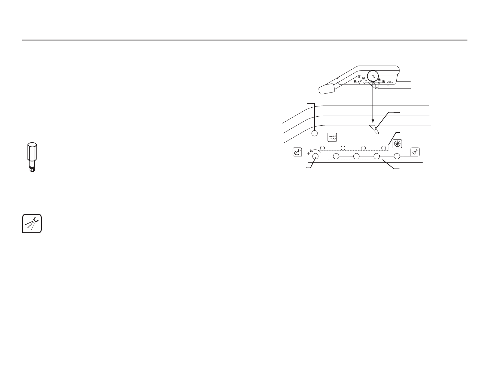
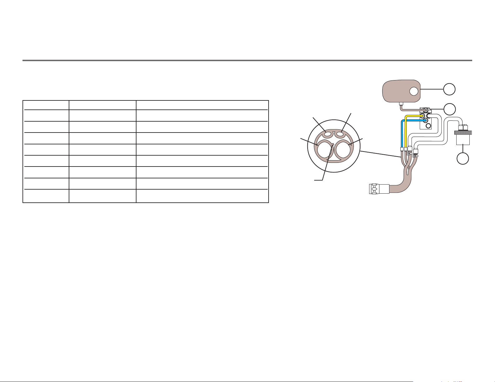
Making Handpiece Control Adjustments
Location of Control Adjustments
The control adjustments for the handpiece flush control,
drive air pressure, coolant air flow, and coolant water
flow are located on the side of the control head.
Operators Adjustments
Use the adjustment key to make adjustments, with the
exception of the drive air pressure. The adjustment key
will not fit the drive air control ports. This was done to
prevent unintentional changes to drive air settings. To
adjust the drive air, use a 3/32" hex key.
85.0812.00, 2003
Handpiece Controls Handpiece Control Adjustments
Location of Control Adjustments on the Control Head
Master On/Off toggle
Handpiece flush control
Coolant water
flow controls
Coolant air flow control
Drive air pressure controls
Adjusting
Coolant Water
Using the adjustment key or a 1/8" hex key, follow these steps to adjust the coolant water flow for
each handpiece. Turn the key clockwise to decrease the coolant water flow and counterclockwise
to increase the coolant water flow.
Task Description
1Insert the key into the adjustment port for the handpiece
being adjusted.
2Turn clockwise until it seats softly.
3Move the foot control’s wet/dry toggle to the ON position (toward blue dot).
4 Run the handpiece at medium speed.
5Adjust the coolant water until 2-3 drops per second are visible.
HC-2
PUSH
I MASTER O
1234
®
PUSH
1234
I MASTER O
Page 3

85.0812.00, 2003 HC-3
Handpiece Controls Handpiece Control Adjustments
Adjusting Coolant
Air
Adjusting
Drive Air
Using the adjustment key (or a 1/8" hex key), follow these steps to adjust the coolant air flow for
each handpiece. Turn the key clockwise to decrease the coolant air flow and counterclockwise to
increase the coolant air flow.
Task Description
1Insert the key into the adjustment port (one location for all handpieces).
2Run the handpiece at medium speed.
3 Adjust the coolant air by turning the key counterclockwise (until a fine mist is
visible around the bur).
Follow these steps to adjust the drive air using a 3/32" hex key.
Task Description
1 Install the handpiece on a drive air pressure gauge.
2 Locate drive air control for the handpiece being adjusted and insert the hex key.
3Install the handpiece gauge on the coupler.
4Move the foot control’s wet/dry toggle to OFF (away from blue dot) and fully depress the foot
control cover.
5Turn the drive air control counterclockwise until the handpiece is running slightly above
the manufacturer’s specified drive air pressure, then turn clockwise until it is at the
specified pressure.
6 Repeat adjustments 1-5 for each handpiece position.
Page 4
85.0812.00, 2003 HC-4
Handpiece Controls Delivery Systems
1
2
3
4
5
6
7
8
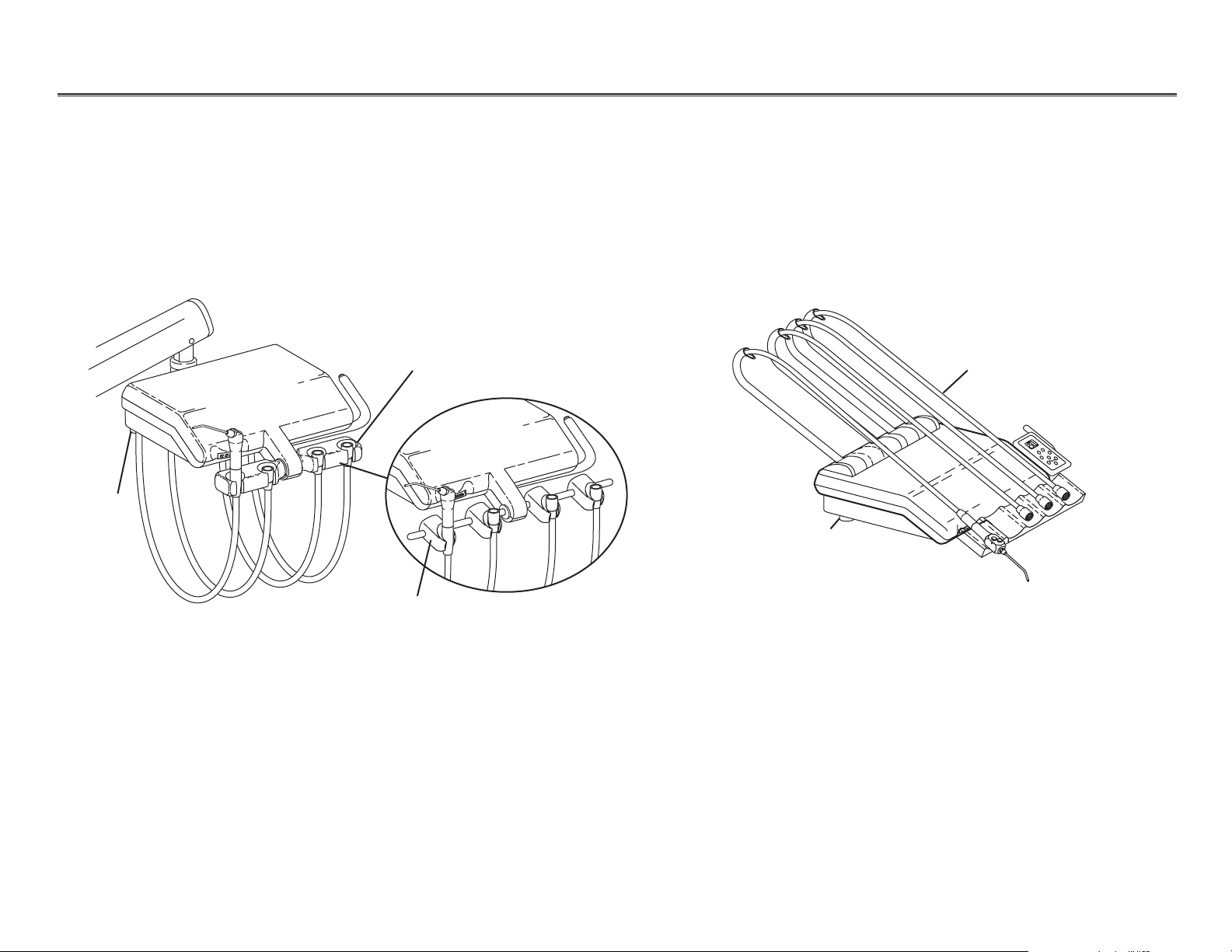
Cascade Traditional Delivery System
Unitized holder
Individual holder
Cascade Continental Delivery System
Continental whip
assemblies
Oil collector
Oil collector
Working with
Delivery Systems
The following pages provide instructions and service information on parts associated with
A-dec’s delivery systems.
8
7
6
5
4
3
2
1
Page 5
85.0812.00, 2003 HC-5
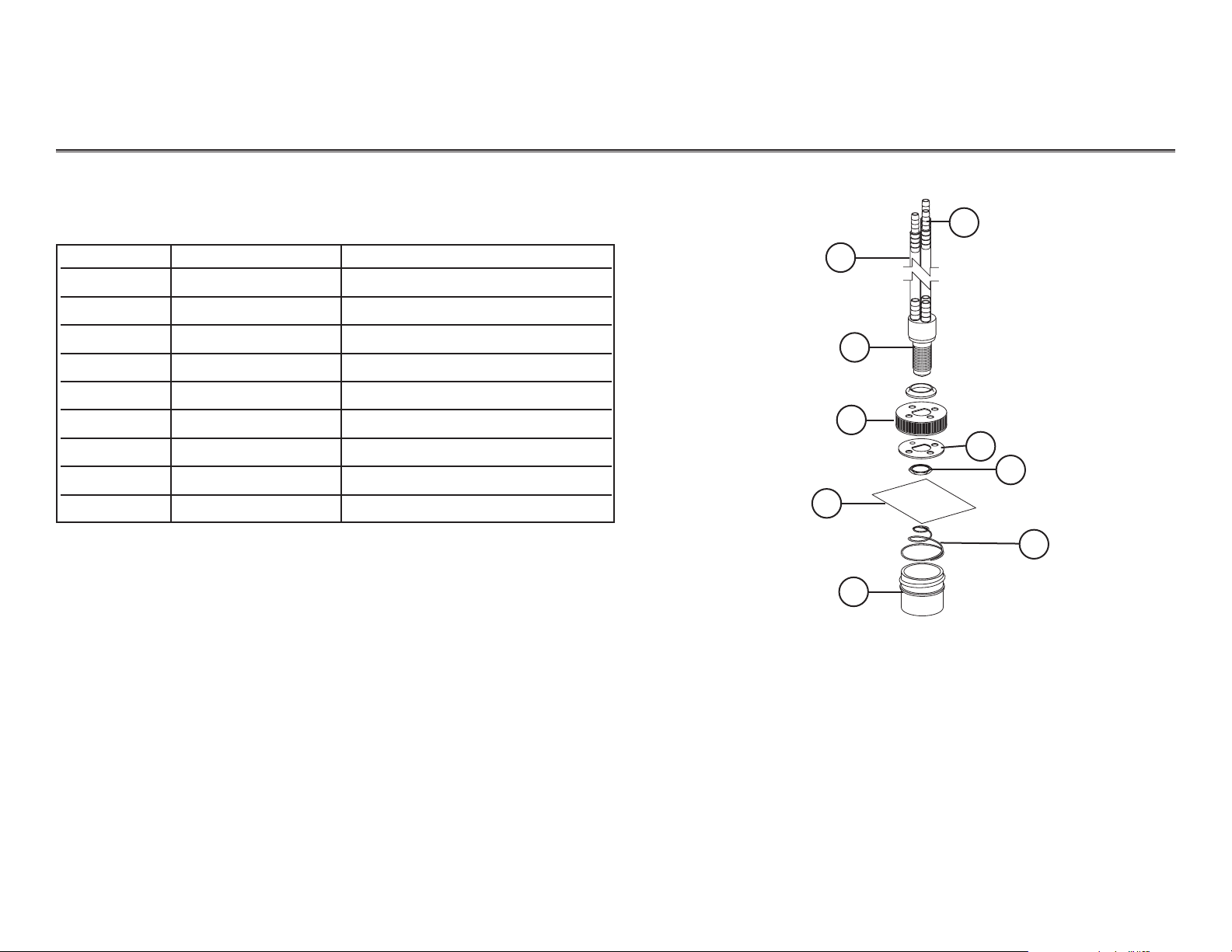
Handpiece Controls Oil Collector
Oil Collector
1
6
2
3
4
5
7
8
9
Item # Part Number Description
1— Clear tubing, 1/4"
2— Oil collector manifold
3 24.0416.00 Cap
4— Gauze pad
5 052.023.00 Jar
6 023.045.02 Inline barbs
7— Deflector spacer
8 006.009.00 Nut
9 013.090.00 Spring
Oil Collector
Page 6
85.0812.00, 2003 HC-6
Handpiece Controls Traditional Holders
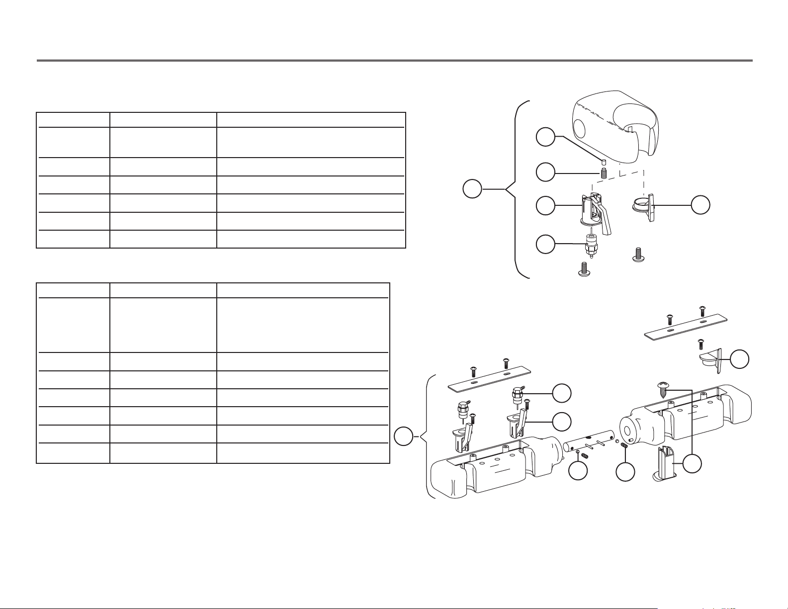
Individual Holder
Unitized Holder (Two and Three-Position)
2
3
4
5
6
7
6
5
Item # Part Number Description
1 99.0583.00 Auto holder assy
99.0584.00 Assistant’s holder assy
2 45.0403.00 Friction pad
3 007.056.00 Setscrew, socket cup point
4 99.0590.00 Actuator, auto holder
5 33.0025.01 Air bleed valve (individual)
6 99.0587.00 Slot plug
Individual Holder
1
2
Item # Part Number Description
1 99.0603.00 Traditional, 3-position
99.0604.00 Traditional, 4-position
99.0605.00 Traditional, 5-position
99.0606.00 Traditional, 6-position
2 33.0132.00 Air bleed valve (unitized)
3 99.0590.00 Actuator, auto holder
4 45.0403.00 Friction pad
5 007.056.00 Setscrew, socket cup point
6 99.0607.00 Plug and screw
7 99.0587.00 Slot plug
Unitized Holder
1
4
3
NOTE: Complete holder replacement is recommended if a holder is
broken. For more information on service parts, see the
Genuine A-dec Service Parts Catalog
(P/N 85.5000.00) or
contact customer service.
Page 7
85.0812.00, 2003 HC-7
Handpiece Controls Traditional Holder Flow Diagrams
Holder and Handpiece Tubing to Control Block
Item # Part Number Description
1 99.0584.00 Single molded holder, assistant, Surf 4
99.0583.00 Single molded holder, auto, Surf 4
99.0629.00 2-position unitized holder, LH
99.0619.00 3-position unitized holder, LH
99.0628.00 2-position unitized holder, RH
99.0618.00 3-position unitized holder, RH
2 38.0509.00 Century Plus control block
3 24.0410.00 Oil collector
1
2
3
Coolant water
Coolant air
Drive air
Exhaust
Rib identifies
drive air
Traditional Holder
D
A
1
W
D
2
Page 8
85.0812.00, 2003 HC-8
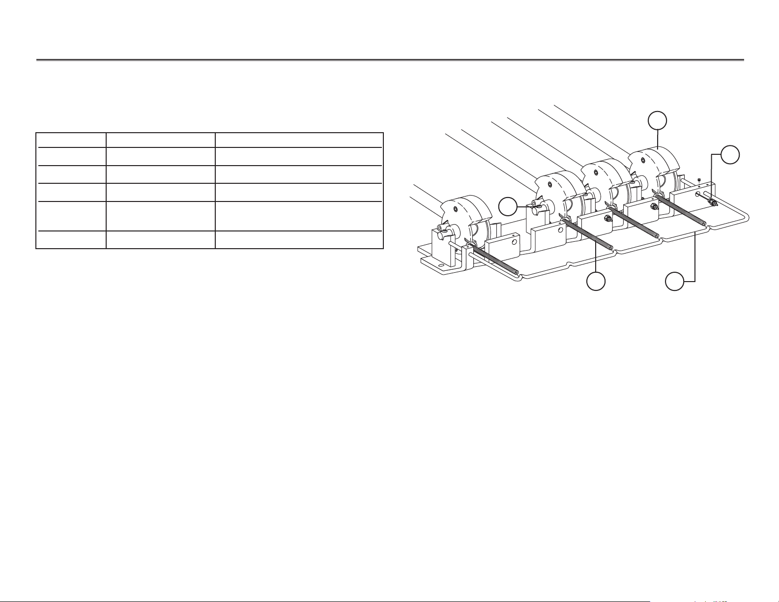
Handpiece Controls Continental Holders
Continental Whip Assembly
1
5
2
3
Item # Part Number Description
1 002.034.01 Screw, button head socket
2 39.1054.00 Continental whip assembly
3 33.0025.01 Air bleed valve, long stem
4 013.015.00 Spring, Red (standard 3 lb pull)
013.027.00 Spring, Green (optional 4 lb pull)
5 39.1053.00 Spring rod
4
Cascade Continental Whip Assembly
Page 9
85.0812.00, 2003 HC-9
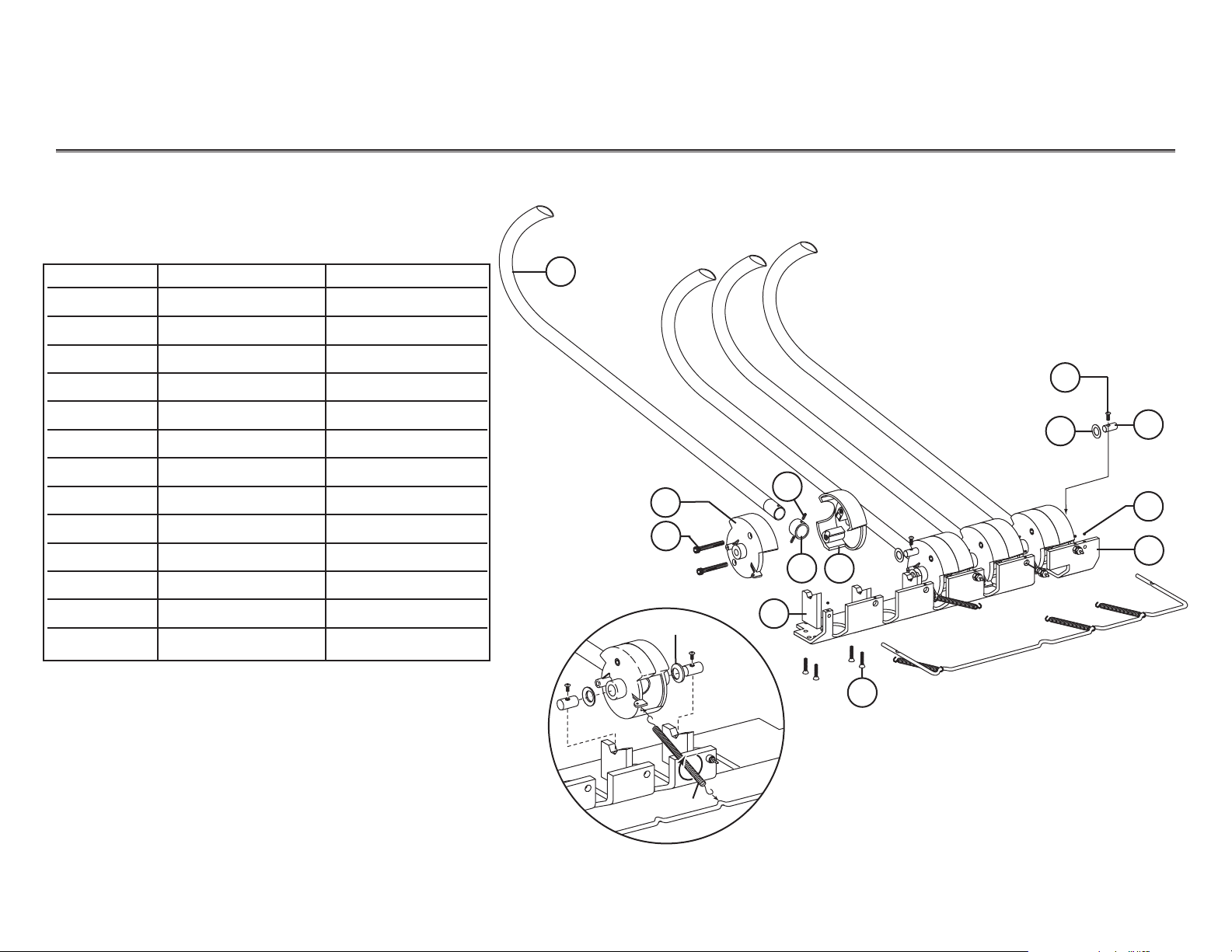
Handpiece Controls Continental Holders
34.1054.00 Continental Whip Assembly
Item # Part Number Description
1 39.1060.00 Whip
2 001.026.00 Screw, socket head
3 75.0066.00 Pivot wheel
4 39.1055.00 Post
5 001.121.01 Screw, socket head
6011.091.00 Spring pin
7 39.1059.00 Whip ring
8 75.0067.00 Pivot wheel
9 004.162.00 Spring washer
10 002.034.01 Screw, button head
11 39.1050.00 Short pin
12 007.010.00 Setscrew
13 39.1052.00 Mounting bracket
1
3
2
8
7
6
4
5
13
12
11
10
9
Spring washer
NOTE: Spring washer curve
is towards the whip
assembly(ies).
Spring
NOTE:Pre-load the spring by rotating it clockwise
until both hooks point up.
Continental Whip
Page 10

85.0812.00, 2003 HC-10
Handpiece Controls Cascade Continental Flow Diagram
Holder and Handpiece Tubing to Control Block
1
2
3
Coolant water
Coolant air
Drive air
Exhaust air
Rib identifies
drive air
Item # Part Number Description
1 99.0613.00 Continental whip assembly, 3-position
99.0614.00 Continental whip assembly, 4-position
99.0615.00 Continental whip assembly, 5-position
2 38.0509.00 Century Plus control block
3 24.0410.00 Oil collector
Continental Holder
D
A
1
W
D
2
Page 11

85.0812.00, 2003 HC-11
Handpiece Controls Syringes
Autoclavable Syringe
Item # Part Number Description
23.1011.00 Autoclavable syringe head assembly
23.1150.00 Autoclavable syringe assembly and 7' tubing
23.1099.00 Autoclavable syringe service kit, 2 button
23.1012.00 Autoclavable syringe service kit, soft button
1 23.1232.01 Valve assembly with o-rings, autoclavable
2 23.1193.01 Screw pkg 5
3 013.064.01 Spring pkg 10
4 23.1112.00 Syringe tip retainer, non-locking
5 035.048.01 O-ring pkg 10
6 034.003.01 O-ring pkg 10
7 23.1028.00 Soft button, autoclavable
8 001.002.01 Screw pkg 5
9 23.1021.01 Valve assembly with o-rings pkg 2
10 013.064.01 Spring pkg 10
11 23.1194.00 Two-button valve conversion kit
1
2
3
4
5
6
7
8
9
10
11
Beginning
October 1995
Before
October 1995
Page 12

85.0812.00, 2003 HC-12
Handpiece Controls Syringe
Syringe Terminal, 2 Barb, Non-Quick Disconnect
Item # Part Number Description
1 030.002.02 O-ring pkg 10
2 23.1015.00 Handle
3 024.155.02 Syringe tubing assembly, straight 7'
1
2
3
23.1208.00
Page 13

85.0812.00, 2003 HC-13
Handpiece Controls Handpiece Tubing Terminals
Item # Part Number Description
1 98.0879.00 Four-hole tubing (straight) with
Midwest terminal, 84" (2134mm), Surf 4
2 98.0882.00 Three-hole tubing (straight) with Borden
terminal, 84" (2134mm), Surf 4
3 98.0262.02 Fiber-optic tubing (straight, with bulb)
84" (2134mm), Surf 4
4 98.0885.00 Fiber-optic tubing (straight), six pin,
84" (2134mm), Surf 4
5 041.317.00 Fiber-optic lamp, Xenon 3.5V, .75 amp
Tubing Terminals
1
2
3
4
5
TubingTerminal
Tubing to Terminal
4-hole
3-hole
5-hole
6-hole
Page 14

85.0812.00, 2003 HC-14
Handpiece Controls Century Plus Control Block
Century Plus Control Block Assembly
Item # Part Number Description
1 38.0524.00 Manifold assembly
38.0528.00 Manifold assembly, Century Plus, IC
2 38.0509.00 Century Plus control block
3 38.0507.01 Gasket
4 38.0505.00 End cap
5 38.0504.06 Tie bolt kit, 2 block
38.0504.07 Tie bolt kit, 3 block
38.0504.08 Tie bolt kit, 4 block
38.0504.09 Tie bolt kit, 5 block
6 004.036.00 Nylon float washer
7 38.0508.00 Nut, special
4
3
2
7
6
5
1
Working with
the Century Plus
Control Assembly
The A-dec Century Plus handpiece control system incorporates a master block, handpiece flush,
and air bleed functions into the control block system, reducing external tubing and connections.
The following pages provide illustrations, flow diagrams, and service information on parts that
are used to maintain and adjust the control block assembly.
2
1
3
0
8
7
6
5
4
3
2
1
Page 15

85.0812.00, 2003 HC-15
Handpiece Controls Century Plus Control Block
Century Plus Control Block Serviceable Parts
Item Part Number Description
1 001.021.01 Screw, socket head
2 001.024.01 Screw, socket head
3 38.0546.00 Cap assembly
4 38.0519.01 Diaphragm
5 38.0514.00 Water valve actuator
6 013.021.00 Spring, compression
7 38.0507.01 Molded side gasket
8 38.0510.00 Drive air flow adjustment stem
035.034.01 Drive air flow adjustment stem w/o-ring
9 38.0516.00 Water flow adjustment stem
035.034.01 Water flow adjustment stem w/o-ring
10 002.118.00 Screw, button head
11 38.0520.00 Water valve cartridge assembly
12 38.0518.00 Check valve (with duckbill) cartridge
13 38.0517.00 Air bleed cartridge (with o-rings)
For information about Century Plus handpiece control kits or A-dec replacement parts,
refer to the Genuine A-dec Service Parts Catalog, P/N 85.5000.00.
Century Plus Control Block
1
3
4
7
5
8
9
10
6
11
12
13
2
D
1
A
W
D
2
Page 16

85.0812.00, 2003
HC-16
Handpiece Controls Control Block Manifolds
38.0524.00 Century Plus Control Block
Manifold for Cascade
Item # Part Number Description
1 38.0526.00 Air coolant stem with o-rings
2 030.003.02 O-ring
3 002.118.00 Screw, button head
4 004.005.02 Washer
5 023.001.03 Barb, 1/4"
6 023.004.03 Barb, 1/8"
7 38.0555.00 Syringe water flow control barb assembly
38.0555.00 Syringe air flow control barb assembly
8 38.0525.00 Flush valve stem with o-rings
9 034.001.01 O-ring, E, .029 10 x .040 W
8
4
5
2
3
6
7
38.0528.00 Century Plus Control Block
Manifold for Decade Carts
6
2
3
4
5
1
1
9
Century Plus Control Block
Page 17

85.0812.00, 2003 HC-17
Handpiece Controls Control Block Flow Diagram
Item# Part Number Description
1 39.0822.00 Horizontal gauge
2 38.0524.00 Century Plus manifold assy
3 33.0048.04 Manual brake toggle
4 29.0146.00 Reverse micro valve, 3-way
5 33.0131.01 Master On/Off toggle
6 40.1075.00 Low voltage water heater
1
3
4
2
6
Master air
Chip blower air
Signal water (coolant water )
Signal air (coolant air)
Drive air
Pilot air
Regulated air
Oral cavity water
Return water
Special use
From air regulator or
post box
5
From air regulator or
foot control
To post box or utilities
From post box or utilities
To post box or utilities
Special use
Electrical accessories power
From post box
Autoclavable syringe
(optional heated syringe tubing shown)
Syringe
water flow
control
Syringe
water flow
control
Flexarm brake
Ground
Number Color Voltage
1Black 0
2Brown0
3Red 6
4Orange 24
5Yellow 24
6Green/Yellow Ground
7Blue 24
8Violet 17
Terminal Strip Wiring Voltage
(before May 1998)
Before May 1999
2345678
1
Page 18

85.0812.00, 2003 HC-18
Handpiece Controls Control Block Flow Diagram
Item Part Number Description
1 39.0822.00 Horizontal gauge
2 38.0524.00 Century Plus manifold assy
3 33.0048.04 Manual brake toggle
4 29.0146.00 Reverse micro valve, 3-way
5 33.0131.01 Master On/Off toggle
6 40.1075.00 Low voltage water heater
1
3
4
2
6
Master air
Chip blower air
Signal water (coolant water )
Signal air (coolant air)
Drive air
Pilot air
Regulated air
Oral cavity water
Return water
Special use
From air regulator or
post box
5
From air regulator or
post box
To post box or utilities
From post box or utilities
To post box or utilities
Special use
Electrical accessories power
From post box
Autoclavable syringe
(optional heated syringe tubing shown)
Syringe
water flow
control
Syringe
water flow
control
Flexarm brake
Number Color Voltage
1Black 0
2Brown0
3Red 6
4Orange 24
5Yellow 24
6Green/Yellow Ground
7 Blue 24
8Violet 17
Terminal Strip Wiring Voltage
(before May 1998)
After April 1998
2345678
1
Page 19

85.0812.00, 2003 HC-19
Handpiece Controls Radius Delivery System Flow Diagram
After November 1999
Control head
Floor box
Radius cuspidor
Foot control
Brake assembly
Flexarm brake
Master On/Off
Century Plus
control block
Air bleed valve
Syringe
Horizontal gauge
Air filter/regulator assembly
Water filter/regulator assembly
(80 psi)
(40 psi — non-adjustable)
(40 psi)
Syringe
Saliva ejector
HVE
Wet/dry
toggle
Chip
blower
Water manifold
Bowl
rinse
Cup
fill
Cup fill
air relay
Water relay
Cup fill
bleed
valve
(Fiber-optic
switch)
Self-contained water
Foot control III valve
34
50
40
60
5
2
30
70
20
80
1
6
90
10
100
0
psi
2
7
0
kg/cm
34
50
40
60
5
2
30
70
20
80
1
6
90
10
100
0
psi
2
7
0
kg/cm
Page 20

85.0812.00, 2003 HC-20
After November 1999
Control head
Floor box
Radius cuspidor
Foot control
Brake assembly
Flexarm brake
Master On/Off
Century
Plus control
block
Air bleed valve
Syringe
Horizontal
gauge
Air filter/regulator assembly
Water filter/regulator assembly
(80 psi)
(40 psi — non-adjustable)
(40 psi)
Syringe
Saliva ejector
HVE
Wet/dry
toggle
Chip
blower
Water manifold
Bowl
rinse
Cup
fill
Cup fill air
relay
Water relay
Cup fill
bleed
valve
(Fiber-optic
switch)
Self-contained water
Foot control III valve
Post box
Handpiece Controls Cascade Delivery System Flow Diagram
a
a
34
50
40
60
5
2
30
70
20
80
1
6
90
10
100
0
psi
2
7
0
kg/cm
34
50
40
60
5
2
30
70
20
80
1
6
90
10
100
0
psi
2
7
0
kg/cm
Page 21

Handpiece Controls Cascade Delivery System Flow Diagram
85.0812.00, 2003 HC-21
Control head
Floor box
Radius cuspidor
Foot control
Brake assembly
Flexarm brake
Master On/Off
Century Plus
control block
Air bleed valve
Syringe
Horizontal
gauge
Air filter/regulator assembly
Water filter/regulator assembly
80 psi pre-regulator
40 psi pre-regulator
Syringe
Saliva ejector
HVE
Wet/dry toggle
Chip blower
or scaler
Water manifold
Bowl
rinse
Cup
fill
Cup fill air
relay
Water relay
Cup fill
bleed
valve
(Fiber-optic
switch)
Self-contained water
Water quick disconnect
Foot control II valve
Before December 1999
Post box
34
50
40
60
5
2
30
70
20
80
1
6
90
10
100
0
psi
2
7
0
kg/cm
a
a
2
1
34
40
30
20
10
0
0
50
60
5
70
80
6
90
100
psi
2
7
kg/cm
Page 22

Handpiece Controls Cascade Control Head Flexarm Adjustment
85.0812.00, 2003 HC-22
Adjusting
Horizontal Drift
(Cascade)
Cascade Control Head Flexarm
Item # Part Number Description
1 35.1514.00 Flexarm assembly
2 007.024.00 Tension setscrew
3 007.058.00 Retaining/alignment setscrew
4 35.1386.00 Rigid arm post assembly
1
4
3
2
To eliminate horizontal drift of the control head, adjust the tension
setscrew. This causes the cup point to seat itself against the wall of
the internal bushing. Use a 3/32" hex key for adjusting both the
tension and the retaining/alignment setscrews.
Page 23

Handpiece Controls Cascade Control Head Flexarm Adjustment
85.0812.00, 2003 HC-23
Adjusting the
Tension
Setscrew
(Cascade)
Adjusting the
Retaining/
Alignment
Setscrew
(Cascade)
Follow these steps to adjust the tension setscrew.
Task Description
1Remove the tension setscrew and the
retaining /alignment setscrew. Reinstall both,
making sure they are in the correct locations.
Do not tighten.
2Tighten the tension setscrew until it comes
to a stop. Then tighten it an additional
quarter turn (20 - 24 inch pounds).
NOTE: It is important to repeat step two. Loosen
the setscrew and repeat the step twice.
This will ensure the setscrew is seated.
3Check flexarm tension and adjust the setscrew
to achieve the desired result.
Follow these points to adjust the retaining/
alignment setscrew.
•Tighten the retaining alignment setscrew
until it passes through the opening of the
bushing and presses against the knuckle.
• Loosen the setscrew a quarter turn.
NOTE: The brass colored tip on the end of the
retaining alignment setscrew shouldn’t
touch the knuckle when loosened a
quarter turn.
Adjustment Setscrews
1
2
Item # Part Number Description
1 007.058.00 Retaining/
alignment setscrew
2 007.024.00 Tension setscrew
Long, black
setscrew with
brass colored tip
Short, silver
colored setscrew
Page 24

Handpiece Controls Radius Control Head Flexarm Adjustment
85.0812.00, 2003 HC-24
Adjusting
Horizontal Drift
(Radius)
Cascade Control Head Flexarm
Item # Part Number Description
1 35.1514.00 Flexarm assembly
2 35.1611.01 Unit mount post assembly
3 007.024.00 Tension setscrew
4 007.058.00 Retaining/alignment setscrew, Black
1
2
4
3
To eliminate horizontal drift of the control head, adjust the
tension setscrew. This causes the cup point to seat itself against
the wall of the internal bushing. Use a 3/32" hex key for adjusting both the tension and the retaining/alignment setscrews.
Page 25

Handpiece Controls Radius Control Head Flexarm Adjustment
85.0812.00, 2003 HC-25
Follow these steps to adjust the tension setscrew.
Task Description
1 Remove the tension setscrew and the
retaining /alignment setscrew. Reinstall
both, making sure they are in the correct
locations. Do not tighten.
2 Tighten the tension setscrew until it comes
to a stop. Then tighten it an additional
quarter turn (20 - 24 inch pounds).
NOTE: It is important to repeat step two.
Loosen the setscrew and repeat the
step twice. This will ensure the
setscrew is seated.
3Check flexarm tension and adjust the
setscrew to achieve the desired result.
Follow these points to adjust the retaining/
alignment setscrew.
•Tighten the retaining alignment setscrew
until it passes through the opening of the
bushing and presses against the knuckle.
• Loosen the setscrew a quarter turn.
NOTE: The brass colored tip on the end of the
retaining alignment setscrew shouldn’t
touch the knuckle when loosened a
quarter turn.
Adjustment Setscrews
1
2
Item # Part Number Description
1 007.024.00 Tension setscrew
2 007.058.00 Retaining/
alignment setscrew
Long, black
setscrew with
brass colored tip
Short, silver
colored setscrew
Adjusting the
Tension Setscrew
(Radius)
Adjusting the
Retaining/Alignment
Setscrew
(Radius)
Page 26

Handpiece Controls Troubleshooting
85.0812.00, 2003 HC-26
Problem
Action
Holder(s) is difficult or too easy
to rotate
Whip assembly(ies) doesn’t
actuate the bleed valve(s)
Adjust the tension by loosening or tightening the friction pad setscrew (see Individual and
Unitized Holder).
Task Descriptions
1Verify spring washers are installed between the whip assembly(ies) and mounting
posts. If missing, install them between the whip assemblies and the whip mounting posts
(see Continental Whip).
2Add washers to both sides of the wheel assembly(ies).
•Remove the button-head screw from the appropriate pin and post.
•Slide the pin away from the whip assembly.
•Install the spring washer between the wheel and post with curved side
toward the whip assembly (see Continental Whip).
•Slide the pin into the pin opening in the whip assembly. Secure the pin
with the screw removed above.
• Repeat for each whip assembly with whisker valve actuation.
If this does not resolve the problem, go to step 3.
3 Inspect the air bleed valves and replace those that are defective.
4Test the whip assemblies with the control head cover in place. Make sure
the handpieces activate and deactivate as the whip assembly is pulled and released.
Tips and troubleshooting information are listed in the following charts to assist in diagnosing
handpiece control problems. These charts are not intended to cover every situation, but do include
the most common problems you may encounter.
Troubleshooting
Handpiece Controls
Page 27

Handpiece Controls Troubleshooting
85.0812.00, 2003 HC-27
Problem Action
Whip assemblies don’t move
freely or interfere with cover
Water leaks from the water vent
hole on control blocks
Check for an improperly aligned mounting bracket. Slightly loosen the two screws securing the
assembly in place (underside of control head). Do not remove the cover. Move the whip assembly
until it moves freely.
Follow these steps to check for water leaks.
Task Descriptions
1Check for a failed water valve cartridge
• determine which block is leaking
• exchange the water valve cartridge with a known good one, and
• test the unit.
2 If the water leakage has stopped, replace the failed water valve cartridge. Retest the unit and
make sure there are no more leaks. If water is still leaking, continue with step 3.
3 Remove the water flow adjustment stem from the control block and inspect the o-ring and stem.
Replace defective parts and test the unit. If water is still leaking, continue with step 4.
4Check for a leaking valve stem
•Tighten the valve stem to make sure it’s not leaking and test the unit.
• If the valve stem is still leaking, exchange it with a known good one and test the unit.
• If the water leakage has stopped, replace the failed valve stem cartridge.
•Test the unit.
5Check for loose tie bolts.
Page 28

Handpiece Controls Troubleshooting
85.0812.00, 2003 HC-28
Problem Action
Coolant water is leaking from
one handpiece control block
Follow these steps to check if coolant water is leaking.
Task Descriptions
1 Remove the valve stem from the control block and inspect the o-ring and stem.
2Replace defective parts and test the unit. If water is still leaking, continue with step 3.
3Check for a leaking valve stem
•Tighten the valve stem to make sure its not leaking. Test the unit.
• If the valve stem still leaks, exchange the cartridge with a known good one.
Retest the unit.
Air or water leakage from one of
the valve assemblies
Air or water leakage from the
syringe nut assembly
No air and/or water from
the syringe
Replace the valve assemblies.
Check the following steps to stop leakage from the syringe nut assembly.
•Make sure the syringe nut assembly is properly installed and tightened. Use a 5/32" hex key
to tighten.
•Replace o-rings, and syringe nut assembly.
Check the following steps to fix the syringe.
• Check to make sure the master On/Off toggle and the air and water supplies are turned ON.
• Check tubing for kinks or breaks.
 Loading...