

Page 1

85.0812.00, 2003 FC-1
Foot Controls Overview
This section provides information for servicing A-dec foot controls. It includes tubing flow
diagrams, exploded illustrations, and troubleshooting tips for Foot Control I, II and III.
Page 2

85.0812.00, 2003 FC-2
Foot Controls Overview
Working with
Foot Controls
Foot Control Valves
A foot control is a foot-operated regulator. Handpieces are operated by using a foot control. A-dec
foot controls are actuated by applying foot pressure on the foot control disk. The pressure applied
to the disk pushes down on a valve assembly allowing air to flow from the valve to handpiece
turbines. This turns on air and water coolant.
The A-dec foot control valve has gone through a number of changes over the years. The type of
foot control you have will determine the valve configuration.
In A-dec Foot Control I, the valve assembly is hex-shaped and uses a piston to actuate the
handpieces. Foot Control II changed the body style of the valve assembly to a square shape and
used a stem assembly for actuation. The Foot Control III valve assembly is also square but uses a
piston for actuation.
In Foot Control I and Foot Control III, the piston seats the exhaust vent against the poppet and
pushes it away from the inlet seat, which opens the valve. When pressure to the foot control cover
is released the piston returns, closing the inlet and exhausting any pressure from the outlet side of
the valve.
In Foot Control II, the foot pressure on the stem assembly passes the fluted surfaces of the stem to
below the inlet o-ring seat, allowing air to flow to the outlet. When foot pressure is released the
stem returns, sealing the inlet at the o-ring. Pressure from the outlet side of the valve is exhausted
as the fluted stem moves above the outlet o-ring seal.
Page 3
85.0812.00, 2003 FC-3
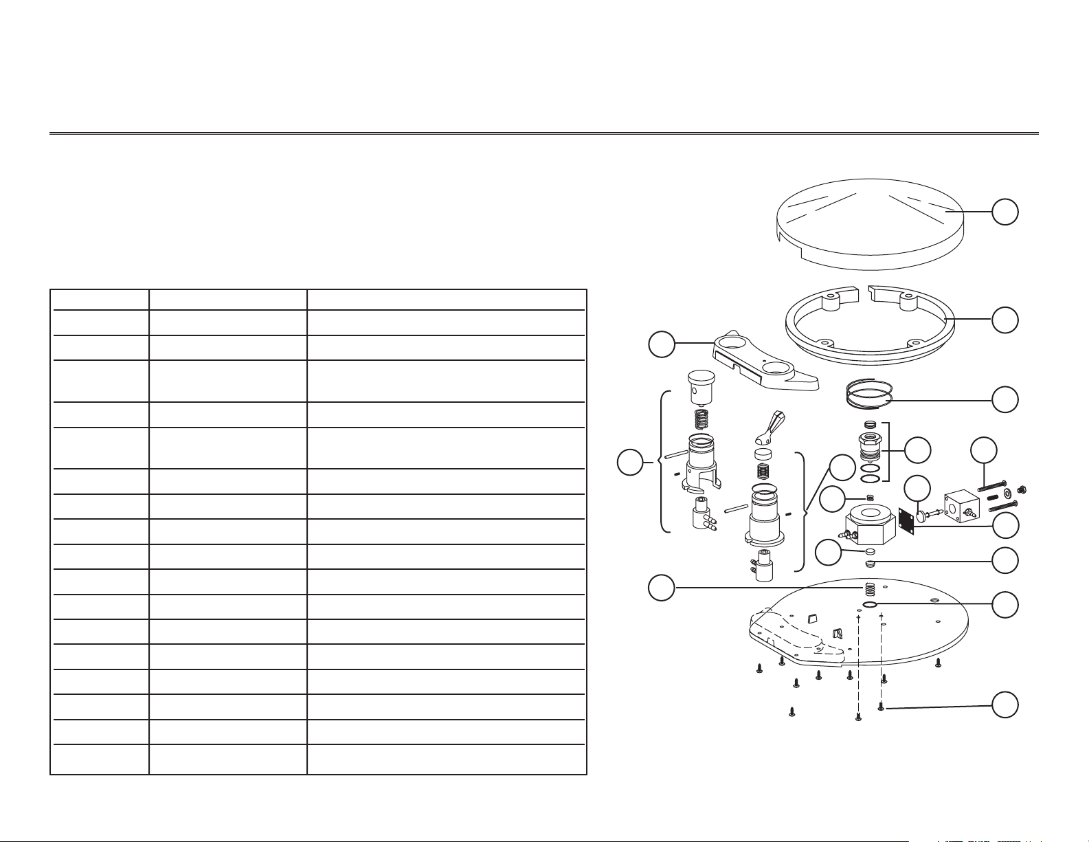
Foot Controls Foot Control I
Item # Part Number Description
— 90.0010.00 Foot Control I field service kit
1 22.0110.00 Foot control cover, fits all foot controls
2 38.0320.00 (01, 02) Foot control housing, 1-hole
38.0321.00 (01, 02) Foot control housing, 2-hole
3 22.0120.00 FC I retaining ring (includes screws)
4 38.0610.00 Chip blower valve
38.0612.00 Scaler valve
*5 22.0135.00 Spring
6 38.0604.00 Wet/dry toggle valve
7 22.0081.00 Piston assembly
*8 22.0580.00 Spring
*9 22.0060.00 Plastic poppet
10 22.0050.00 Spring cap
*11 030.016.02 O-ring pkg 10
*12 22.0040.00 Spring
*13 10.0440.00 Spring
*14 22.0778.00 Signal relay valve stem
*15 38.0054.02 Diaphragm pkg 10
16 002.015.00 Screw, pan head phillips pkg 2
Foot Control I
7
9
1
3
2
4
6
5
8
10
11
12
This information applies to foot controls used before October 1999
(38.0010.00, 38.0035.00, 38.0039.00, 38.0040.00 38.0041.00, 38.0045.00,
38.0050.00, 38.0053.00 and 38.0061.00).
15
14
13
16
Foot Control I
NOTE: Asterisk (*) signifies parts that are included in the field service kit.
Before October 1999
Page 4
85.0812.00, 2003 FC-4
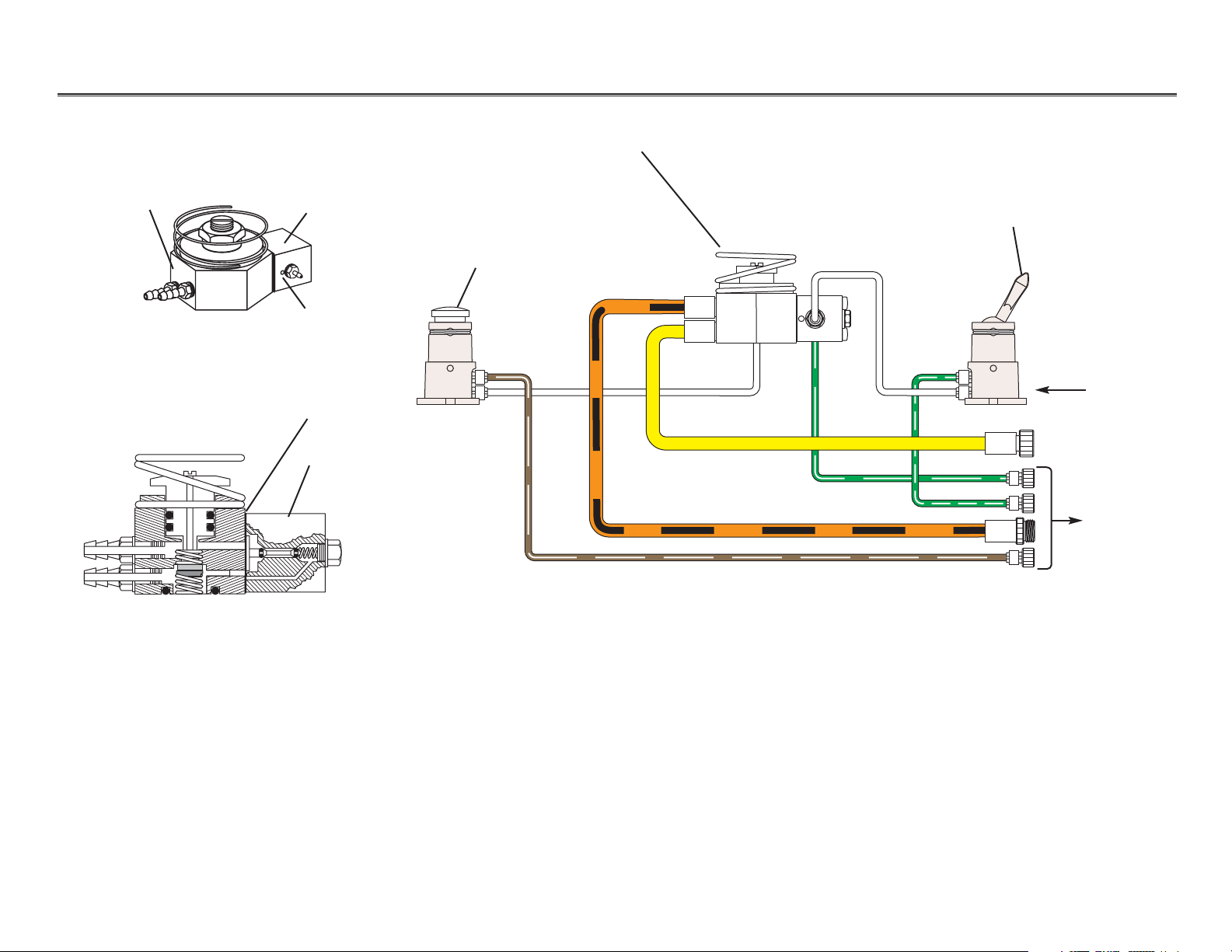
Foot Controls Foot Control I Flow Diagram
Optional chip blower
or scaler valve
Foot Control I valve
Wet/dry toggle
valve
From air
regulator
To control
head
Foot Control I Cross View
Signal relay
valve
Diaphragm
Foot Control I Valve Assembly
Foot Control I
valve
Signal
relay valve
Exhaust hole
Page 5
85.0812.00, 2003
FC-5
Foot Controls Foot Control II
Item # Part Number Description
— 90.0312.00 Foot control II field service kit
1 22.0110.00 Foot control cover, fits all foot controls
2 38.0237.00 Retaining ring, internal, Black
3 38.0320.00 (01, 02) Foot control housing, 1-hole
38.0321.00 (01, 02) Foot control housing, 2-hole
4 38.0610.00 Chip blower valve
38.0612.00 Scaler valve
*5 38.0246.00 Stem with E-ring
*6 38.0552.00 Ring return valve stem
7 38.0604.00 Wet/dry toggle valve
*8 013.011.00 Spring
*9 030.008.02 O-ring, AS568-008
*10 38.0054.02 Diaphragm
11 38.0056.00 Replacement signal relay valve
*12 030.012.02 O-ring, AS568-012
13 003.078.00 Socket head screw
Foot Control II
8
9
1
2
3
4
7
5
10
11
6
13
12
Foot Control II
WARNING
Turn the master On/Off toggle to the OFF position and bleed
system air pressure before removing the foot control disc to
prevent the foot control stem from being forcefully ejected.
NOTE: Asterisk (*) signifies parts that are included in the field service kit.
Page 6

85.0812.00, 2003 FC-6
Foot Controls Foot Control II Flow Diagram
Optional chip blower
or scaler valve
Foot Control II valve
Wet/dry
toggle valve
From air
regulator
To control
head
Foot Control II Cross View
Signal
relay valve
Diaphragm
Foot Control II Valve Assembly
Foot Control II
valve
Signal
relay valve
Exhaust hole
WARNING
When working on Foot Control II, move the master On/Off
toggle to the OFF position and bleed the system of air
pressure. Do this before removing the foot control disc to
prevent the foot control stem from being forcefully ejected
from the foot control valve.
Page 7

85.0812.00, 2003 FC-7
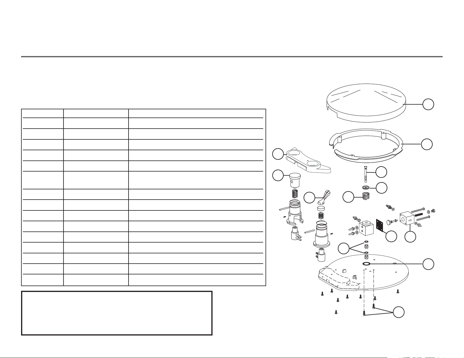
Foot Controls Foot Control III
Use of Foot Control III began in March 1999.
Item # Part Number Description
— 90.0593.00 Foot Control III field service kit
— 38.1764.00 International conversion kit
1 22.0110.00 Foot control cover, fits all foot controls
2 38.0237.00 Retaining ring, internal, Black
3 38.0763.00 Foot control housing, 1-hole, Dark Surf
38.0321.00 (01, 02) Foot control housing, 2-hole
4 38.0610.00 Chip blower valve
38.0612.00 Scaler valve
5 38.0604.00 Wet/dry toggle valve
6 013.011.00 Spring, helical compression
7 38.0054.02 Diaphragm
8 10.0440.00 Spring
9 22.0050.00 Spring cap
10 030.012.02 O-ring, AS568-012
11 22.0060.00 Poppet, plastic
12 22.0580.00 Spring
13 003.078.00 Socket head screw
Foot Control III
8
1
2
3
4
5
13
12
6
11
9
10
7
Foot Control III
Page 8

85.0812.00, 2003 FC-8
Foot Controls Foot Control III Flow Diagram
Optional chip blower
or scaler valve
Foot Control III valve
Wet/dry
toggle valve
From air
regulator
To control
head
Foot Control III Cross View
Signal relay
valve
Diaphragm
Foot Control III Valve Assembly
Foot Control III
valve
Signal
relay valve
Exhaust hole
Page 9

85.0812.00, 2003 FC-9
Foot Controls Valve Assemblies
Chip Blower Valve or
Scaler Valve Assembly
Item # Part Number Description
1 38.0070.00 Valve actuator button
2 22.0040.00 Spring
3 010.056.00 Retainer, spring
4 38.0072.03 Valve holder, Dark Surf
5011.016.00 Pin
6 007.002.01 Set screw, socket cup point
7 33.0134.00 2-way micro-valve (for chip blower - brass ball)
33.0138.00 3-way micro-valve (for scaler - stainless steel ball)
— 38.0510.00 Chip blower valve
— 38.0612.00 Scaler valve assembly
1
5
6
7
2
3
4
Ball
The chip blower is used to send a jet of air through the handpiece, to remove
accumulated debris. Parts available for the chip blower/scaler valve assembly are
detailed in the table.
Recognizing Parts for Chip
Blower/Scaler Valve Assemblies
Page 10

85.0812.00, 2003 FC-10
Foot Controls Valve Assemblies
Wet/Dry Toggle Valve Assembly
Item # Part Number Description
1 38.0075.03 Toggle kit (includes the spring, retainer and pin)
2 38.0066.00 Cap, spring
3 22.0040.00 Spring
4 007.002.01 Set screw, socket cup point
5 38.0072.03 Valve holder, Dark Surf
6 33.0138.00 3-way micro-valve (stainless steel ball)
— 38.0604.00 Wet/dry valve assembly
— 38.0075.03 Service kit
1
2
3
5
4
6
Ball
Wet/Dry Valve Assembly
Page 11

85.0812.00, 2003 FC-11
Foot Controls Troubleshooting
Problem
Action
Audible leakage when foot
control is not being used
Do these steps in the order listed, until the leakage has stopped.
Task Descriptions
1 Check mounting screws in the bottom of the baseplate to make sure they are tight.
• If leakage has stopped, test unit.
• If there is still audible leakage, continue with step 2.
2Remove the cover and check the internal tubings for secure connections.
3 Check for leakage from the exhaust holes on the signal relay valve. If there is leakage, do
the following
•move the master On/Off toggle to the OFF position and bleed
the system of air pressure
• inspect the stem and o-rings for debris or defects, and
•inspect the seat for debris or defects.
4Replace any defective parts. Lubricate the o-rings, reassemble and test the foot control.
5 Check for leakage around the diaphragm. If there is leakage, do the following:
•Tighten the two screws securing the signal relay valve to the foot control
valve. If there’s still leakage, replace the diaphragm.
Tips and troubleshooting information are listed in the following charts to assist in diagnosing foot
control problems. These charts are not intended to cover every situation, but do try to include the
most common problems you may encounter.
Troubleshooting
Foot Controls
Page 12

85.0812.00, 2003 FC-12
Foot Controls Troubleshooting
Problem
Action
Audible leakage when foot
control is in use
Do these steps in the order listed, until the leakage has stopped.
Task Descriptions
1Check for a failed diaphragm.
•Tighten the two screws securing the signal relay valve to the foot control valve. If there is
still leakage replace the diaphragm.
• If there is still audible leakage, continue with step 2.
2 Check for leakage from the exhaust holes on the signal relay valve. If there is leakage, do
the following
•move the master On/Off toggle to the OFF position and bleed the system of air pressure
• inspect the stem and o-rings for debris or defects, and
•inspect the seat for debris or defects.
3Replace any defective parts. Lubricate the o-rings, reassemble and test the foot control.
4 Check the outlet barb and tubing on the signal relay valve. Tighten the barb, or replace
the tubing.
Page 13

85.0812.00, 2003 FC-13
Foot Controls Troubleshooting
Problem
Action
Inadequate air flow
Coolant water continues after
release of foot control
Check these in the following order.
Task Descriptions
1 Check the air pressure. If the air pressure drops by more than 15 psi when syringe air button
and foot control are depressed
•Check for pinched foot control tubing.
• Check for a plugged filter in the air filter/regulator (floor box).
•Check for obstructed outlet barb on signal relay valve.
2Move the master On/Off toggle to the OFF position and bleed the system of air pressure.
3 Remove debris and replace any defective parts in the valve assembly. Lubricate the o-rings,
reassemble, and test the foot control.
Check these in the following order.
1Check for a sticky signal relay valve.
2Move the master On/Off toggle to the OFF position and bleed the system of air pressure.
3Remove the signal relay valve, clean and lube the parts, and reassemble.
4Test foot control.
5 Check for a kinked/plugged tubing somewhere between the foot control relay and the
control head.
Page 14

85.0812.00, 2003 FC-14
Foot Controls Troubleshooting
Sluggish foot control
Follow these steps to test the response on the foot control.
Task Descriptions
1 Check the valve stem to see if it is sticking.
2Move the master On/Off toggle to the OFF position and bleed the system of
air pressure.
3Remove the signal relay valve, clean and lube the parts, and reassemble.
4Test foot control.
Problem
Action
Page 15

85.0812.00, 2003 FC-15
Foot Controls Notes
Page 16

85.0812.00, 2003 FC-16
Foot Controls Notes
 Loading...