

Page 1
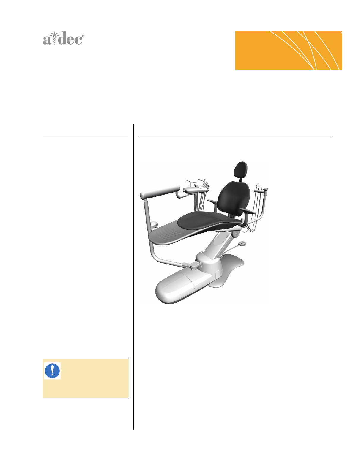
A-dec 300® System
I NSTALLATION GUIDE
C ONTENTS
Introduction ................... 1
Install the Chair ............... 3
Install the Support Center .. 9
Install the Assistant's
Instrumentation ............. 15
Install the Delivery System 22
Install the Dental Light .... 34
Install the Monitor Mount . 36
Install the Contoured Floor
Box ............................ 37
Install the Remote Floor
Box ............................. 39
Connect the Utilities ....... 40
Install the Cuspidor ........ 60
Install Upholstery ........... 61
Prepare and Adjust the
System ........................ 64
Level the System ........... 77
Touchpad Settings .......... 80
Test the System ............. 93
Verify Proper Clearance
Between the Cuspidor Bowl
and the Armrest ............ 94
Install the Covers ........... 96
Appendix: Install the Air
Vacuum System (AVS) .....105
Regulatory Information ...108
NOTE Information that
is critical to a successful
and safe installation is
shaded like this note
throughout the guide.
I NTRODUCTION
This document contains installation instructions for the A-dec 300 system.
Before you begin:
• Clear the room of all debris and thoroughly clean the floors.
• Check that manual air and water shut-offs are installed.
• Purge any debris from air and water lines.
• Check with local building and code authorities about installation
requirements. They differ from state to state and internationally.
Your installation may not require all components described in this document.
Before you begin:
86.0087.00 Rev E
1. Assess what modules you will install.
2. Use “Installation Sequence” on page 2 to note the order of the modules
that are to be installed.
Page 2
A-dec 300 System Installation Guide
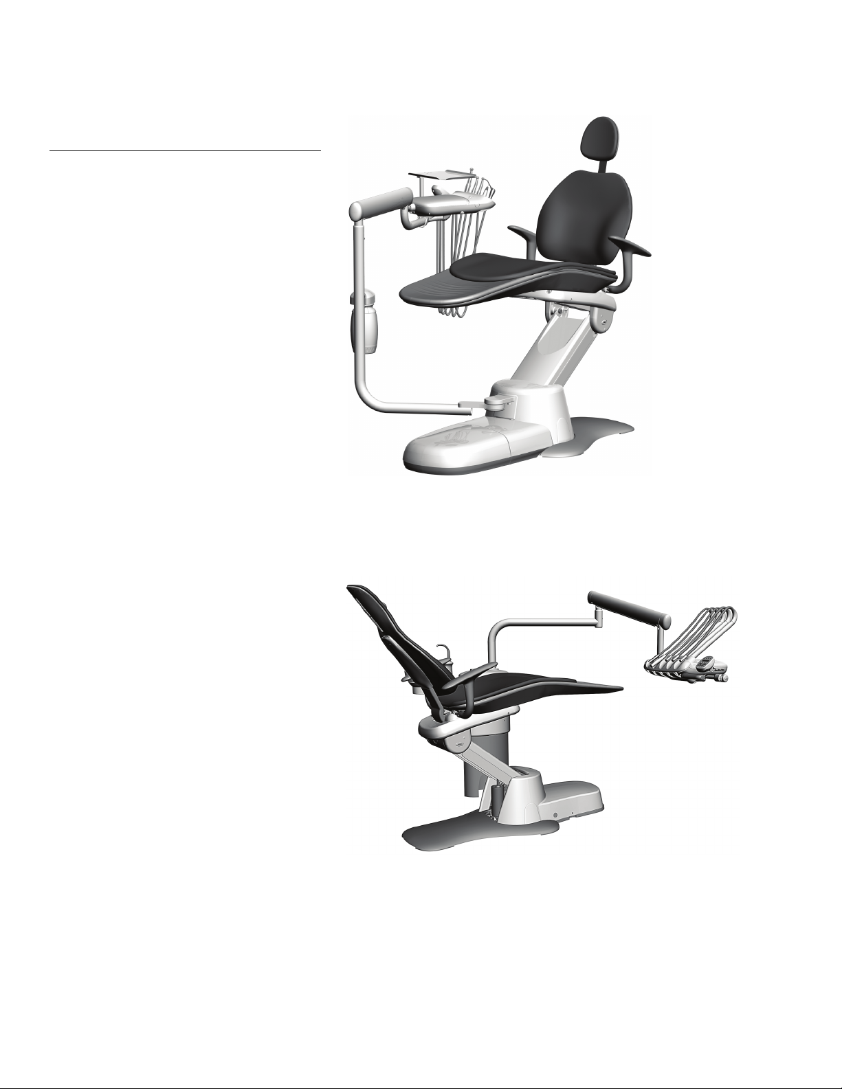
Dental Chair
Support Center
Assistant’s Instrumentation Monitor Mount
Dental Light
Delivery System
2
3
4
5
6
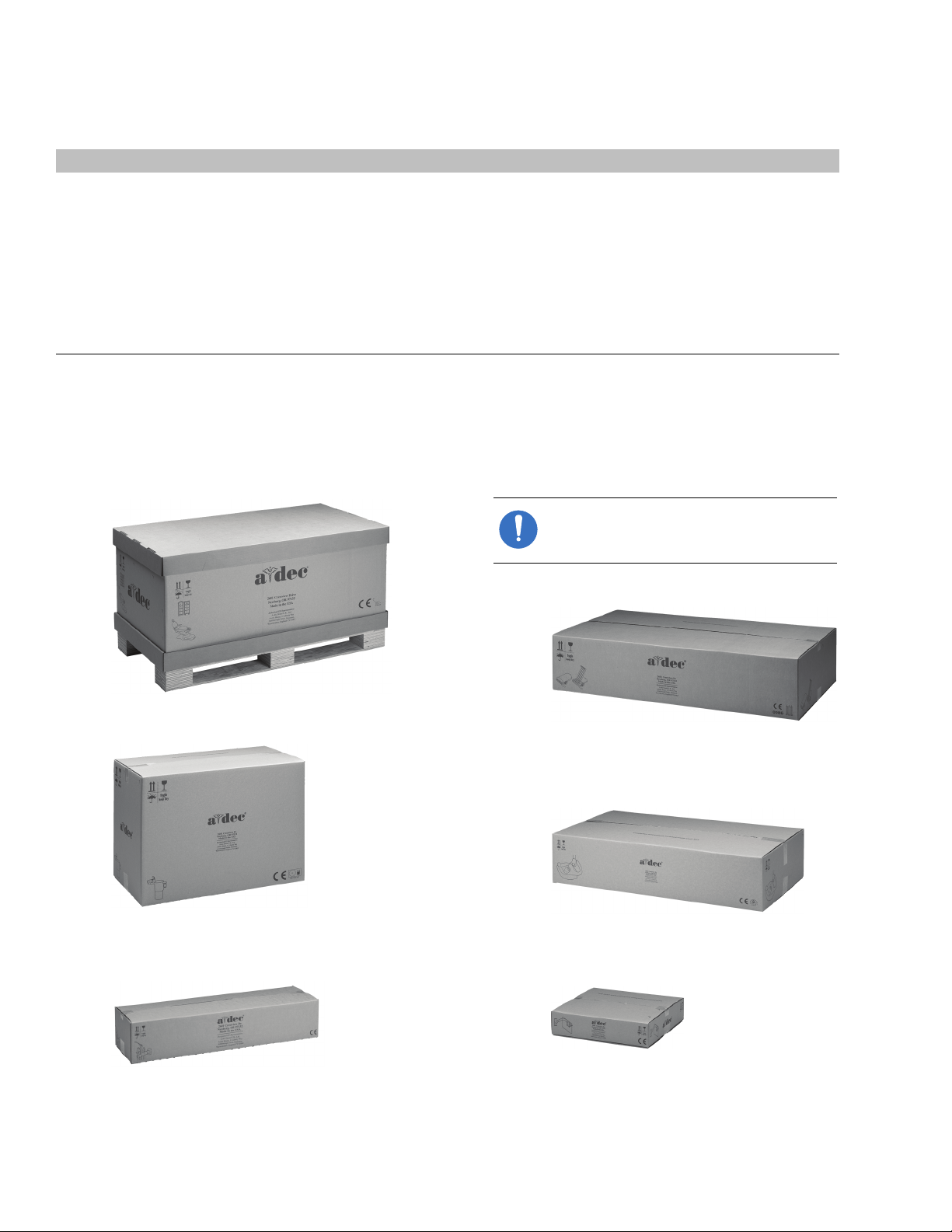
NOTE The box for each module contains
all of the parts needed to install that
module.
1
Recommended Tools
Tools Needed For This Installation
Hex key set Drill
5/16" hex key driver Diagonal cutters A-dec silicone lubricant
Ball driver set Needle nose and standard pliers Umbilical snake
Adjustable wrench Phillips head screwdriver Rubber mallet
3/4" and 9/16" socket and ratchets Roto hammer drill Sleeve pusher
1/4", 1/2", and 3/4" combination
wrenches
Tape measure Pliers
Magnetic level Voltmeter
Drill bits: 3/8" wood, 1/4"
and 1/2" masonry
Installation Sequence
Modules for the A-dec 300 system installation are shown in Figure 1. Install the modules for your configuration in
the order they are listed.
Figure 1. A-dec 300 System Shipping Boxes
2 86.0087.00 Rev E
Page 3
I NSTALL THE
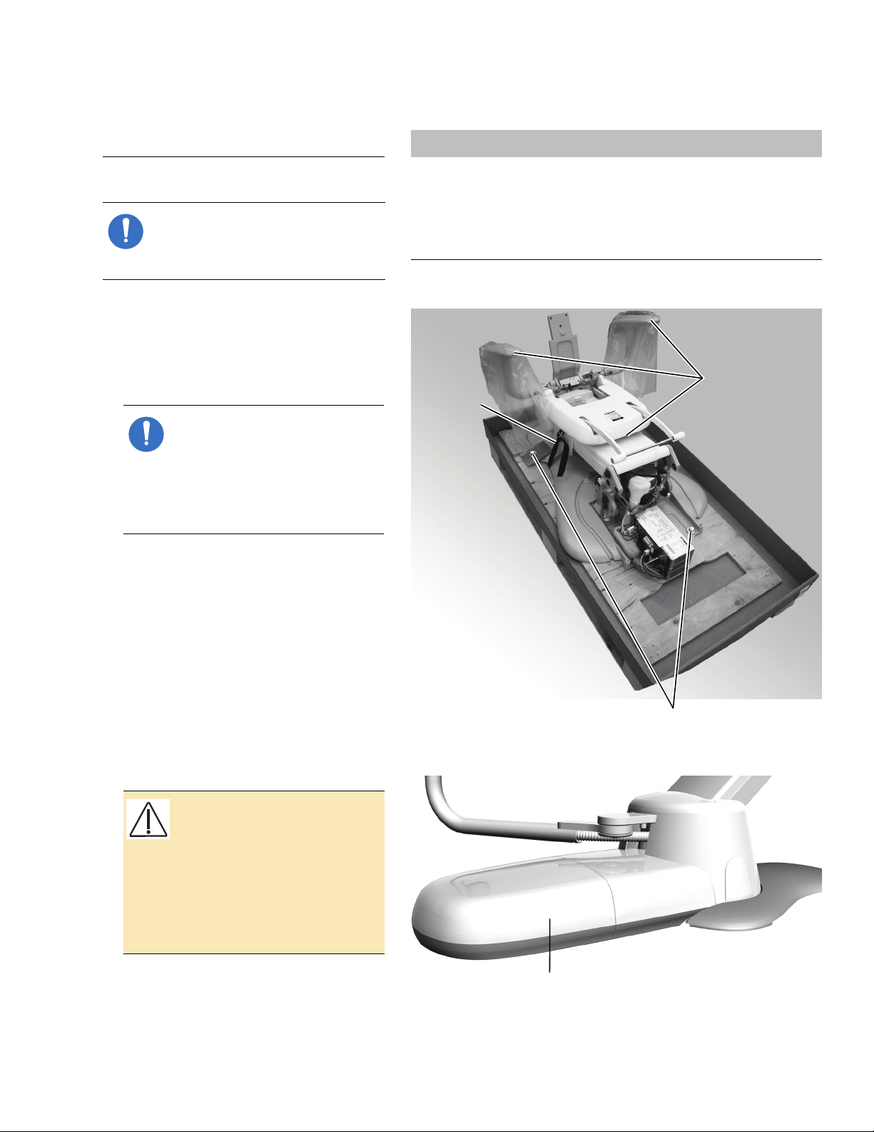
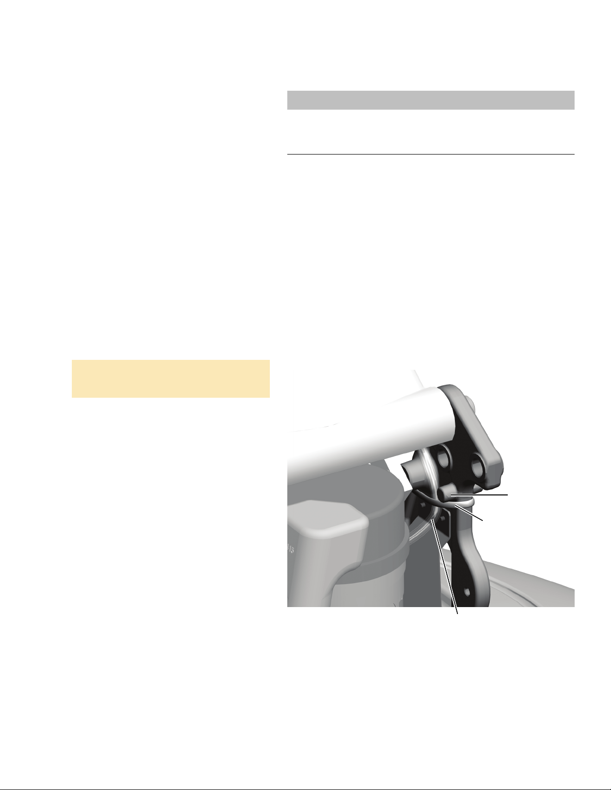
Grab Points
Shipping
Strap
Shipping Bolts
Contoured Floor Box
Install the Chair
C HAIR
NOTE If you have a post mount
system, skip this section and go to
“Install the Support Center” on
page 9.
Position the Chair
1. Remove all items and cardboard from
around the chair.
NOTE When removing modules
from their packaging, watch for
kits and manuals included for
the doctor (such as the A-dec 311
Dental Chair Instructions For Use).
Set these aside during
installation.
Tools Needed For This Section
and 9/16" socket and
3/4"
ratchets
Drill 3/16" hex key
Roto hammer drill 3/4" combination wrench
Phillips head screwdriver
Figure 2. Place the Chair
3/8" wood drill bit or
1/4" and 1/2"
masonry drill bits
2. Remove the covers.
3. Use a 3/4" socket and ratchet to remove
the bolts securing the chair to the pallet.
4. Grasp an armrest and the front of the
chair frame. Lift and place the chair in
position in the treatment room.
CAUTION If the system includes
a contoured floor box, failure to
provide enough space between
the utilities and the contoured
floor box cover will prevent the
installation of the power supply
cover. For more information, see
“Install the Contoured Floor Box
Frame” on page 37.
Figure 3. Contoured Floor Box
5. Remove the shipping strap and the
packaging from the armrests.
86.0087.00 Rev E
3
Page 4
A-dec 300 System Installation Guide
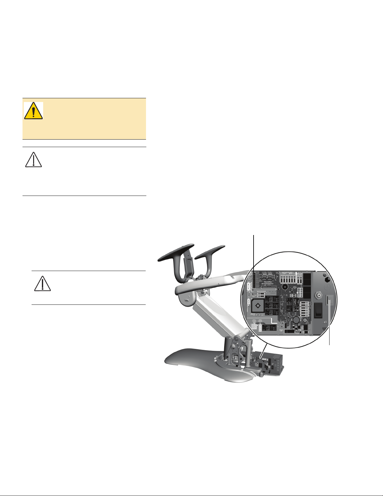
Mains
On/Off
Button
P3
Anchor the Chair
Use the lag screw or masonry anchor with
the cleat to anchor the chair to the floor.
Select the procedure for your type of
flooring structure.
WARNIN G Anchoring the chair to
the floor is required for mechanical
stability. Failure to anchor properly
could result in damage, serious
injury, or death.
CAUTION Check the flooring
and/or framing material where you
will anchor the chair. If it is not at
least 3-1/4" (82 mm) thick, contact a
licensed contractor about
reinforcing the floor.
Anchor to a Concrete Floor
Prepare the Installation Area
1. Plug in the chair and press the Mains
On/Off button on the lower right of the
power supply to turn it on.
CAUTION Electric components
on the circuit board are static
sensitive and require handling
precautions.
2. Move the jumper in P3 of the chair circuit
board to the Base Up position. Once the
chair is raised, return the jumper to the
Spare position.
3. Turn off the power.
4. Unplug the chair.
Figure 4. Prepare the Chair
4 86.0087.00 Rev E
Page 5
5. Place the cleat in the large circle in the
Cleat
Masonry
Anchor
chair base (see Figure 5).
6. Mark where to drill the hole for the
masonry anchor and move the chair.
7. Use a 1/2" bit and roto hammer to drill a
4" (101 mm) deep hole; then remove any
debris.
Install the Chair
Secure the Chair
1. Drive the 3-1/2" masonry anchor into the
hole until the washer is flush with the
floor.
2. Use a 9/16" socket and ratchet to tighten
the anchor until it is securely fixed in the
hole then remove the screw and washer.
3. Return the chair to position.
4. From the left front of the chair, place the
screw through the washer and cleat and
into the hole.
5. Use a 9/16" socket and ratchet to tighten
the bolt against the cleat until it firmly
holds the chair to the floor.
Figure 5. Anchor the Chair to a Concrete Floor
86.0087.00 Rev E
5
Page 6
A-dec 300 System Installation Guide
Cleat
Lag Screw
3/4"
Socket
and
Ratchet
Lag
Screw
3/4" Combination Wrench
Cleat
Anchor to a Wood Floor
Prepare the Installation Area
1. Plug in the chair and press the Mains
On/Off button on the lower right of the
power supply to turn it on (see Figure 4
on page 4).
CAUTION Electric components
on the circuit board are static
sensitive and require handling
precautions.
2. Move the jumper in P3 of the chair circuit
board to the Base Up position. Once the
chair is raised, return the jumper to the
Spare position.
3. Turn off the power and unplug the chair.
4. Place the cleat in the large circle in the
chair base.
5. Mark where to drill the hole for the lag
screw and move the chair.
6. Use a 3/8" bit to drill a 2" (50 mm)
deep hole; then remove any debris.
7. To thread the hole, use a 3/4" socket and
ratchet to drive the 2-1/2" lag screw
about 1/2" (12.8 mm) into the hole; then
remove the lag screw.
Figure 6. Start the Lag Screw
Figure 7. Tighten the Lag Screw
Secure the Chair
1. Put the chair back into position so that
the hole is positioned on the right rear
edge of the circle in the chair base (see
Figure 6).
2. From the right rear of the chair, place the
lag screw through the cleat and into the
hole.
3. With your fingers, start the lag screw as
far as you can; then use a 3/4" socket and
ratchet with a short extension to tighten
the lag screw until it is almost flush
against the cleat.
4. Move the chair into position and use a
3/4” combination wrench to tighten the
lag screw against the cleat until it firmly
holds the chair to the floor.
6 86.0087.00 Rev E
Page 7
Install the Chair
Integrated Floor Box
Cover Frame
Power Supply Cover Frame
Power Supply
Cover Frame
Attach Frame
to Floor
Mains On/Off Button
Attach Frame to
Chair Base
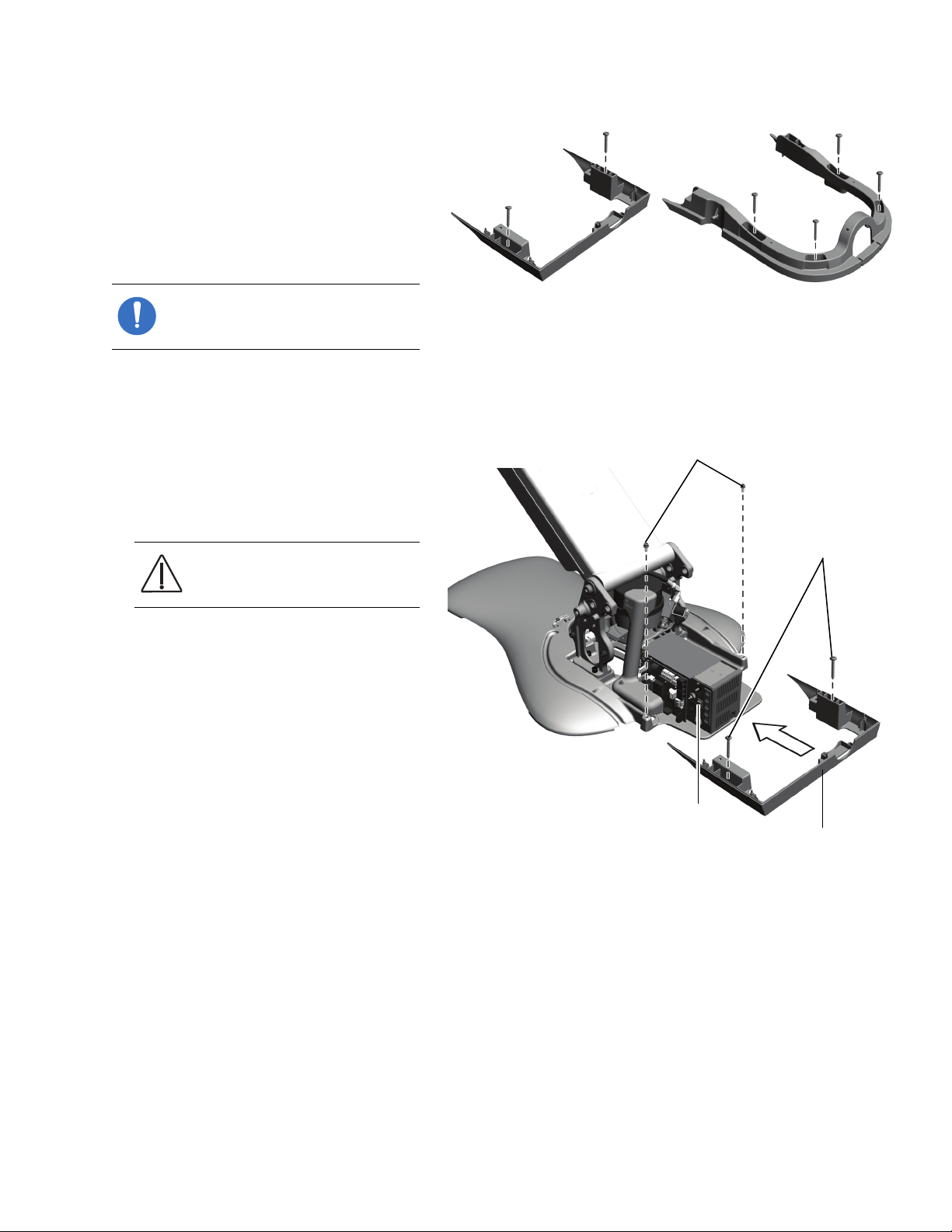
Install the Power Supply or Integrated Floor Box Cover Frames
A-dec 300 systems come with either a power
supply cover or an integrated floor box
cover.
NOTE The power supply cover
frame ships attached to the power
supply cover.
The steps for installing their frames are the
same.
1. With the chair fully raised, use a 3/16"
hex key to remove the two mounting
screws from the chair base.
2. Attach the cover frame to the chair base
with the two mounting screws.
CAUTION Never use a cover
frame as a handle when moving
the chair.
Figure 8. Cover Frames
Figure 9. Install the Cover Frame
3. Attach the cover frame to the floor.
○ If the floor is made of wood, use a
Phillips head screwdriver and 1-1/4"
size #10 screws.
○ If it is a concrete floor, use a 1/4"
masonry drill bit to make holes where
the screws fit through the frame.
Insert the plastic anchors in the holes
then use a Phillips head screwdriver
and 1-1/4" size #10 screws.
86.0087.00 Rev E
7
Page 8
A-dec 300 System Installation Guide
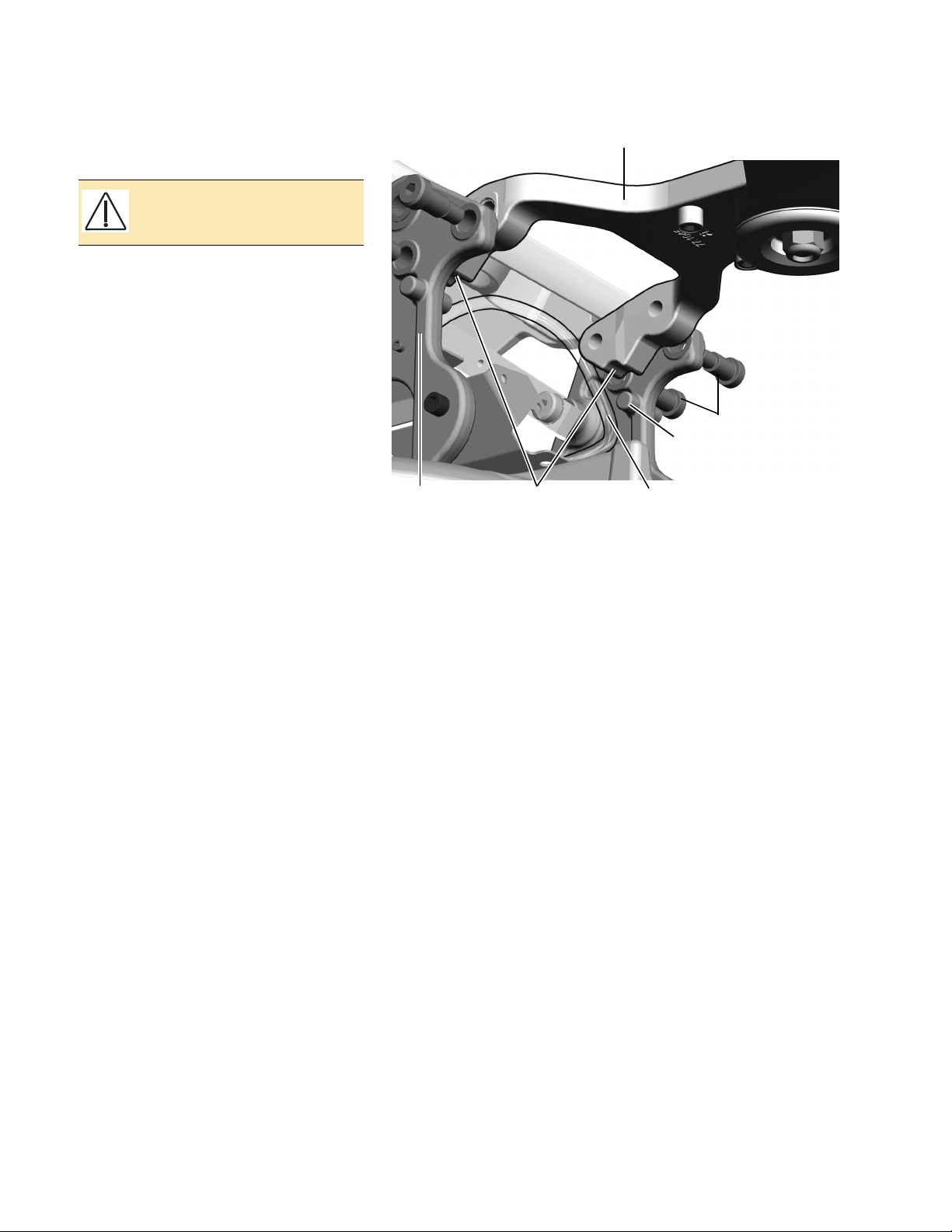
Back Support
Mounting Screws
Chair Back
Strain
Relief
Circuit Board
Touchpad Or Footswitch Connection
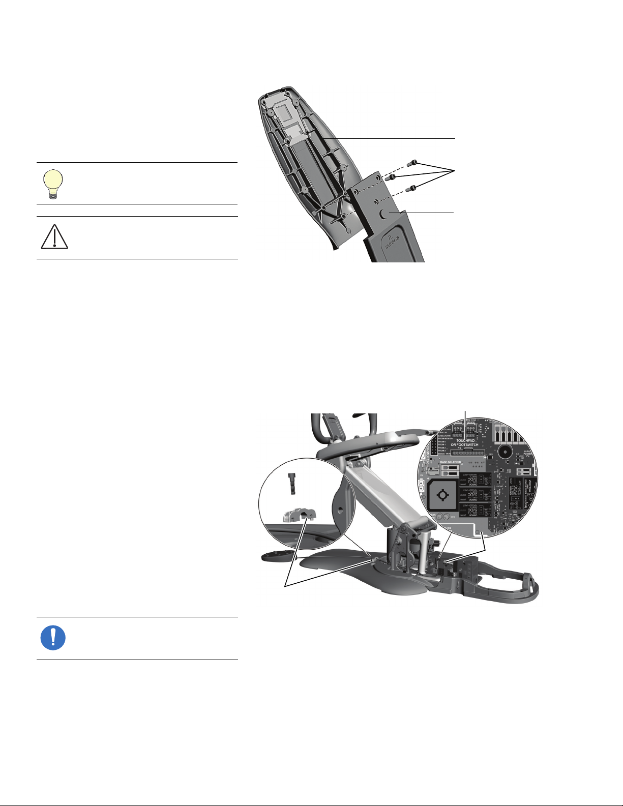
Install the Back Support
1. Use a 3/16" hex key to remove the 3
mounting screws from the back support.
2. Attach the back support to the chair
back with the mounting screws.
TIP Start all three screws before
tightening them.
CAUTION Be sure to tighten the
screws firmly to avoid the back
becoming loose during use.
Figure 10. Install the Back Support
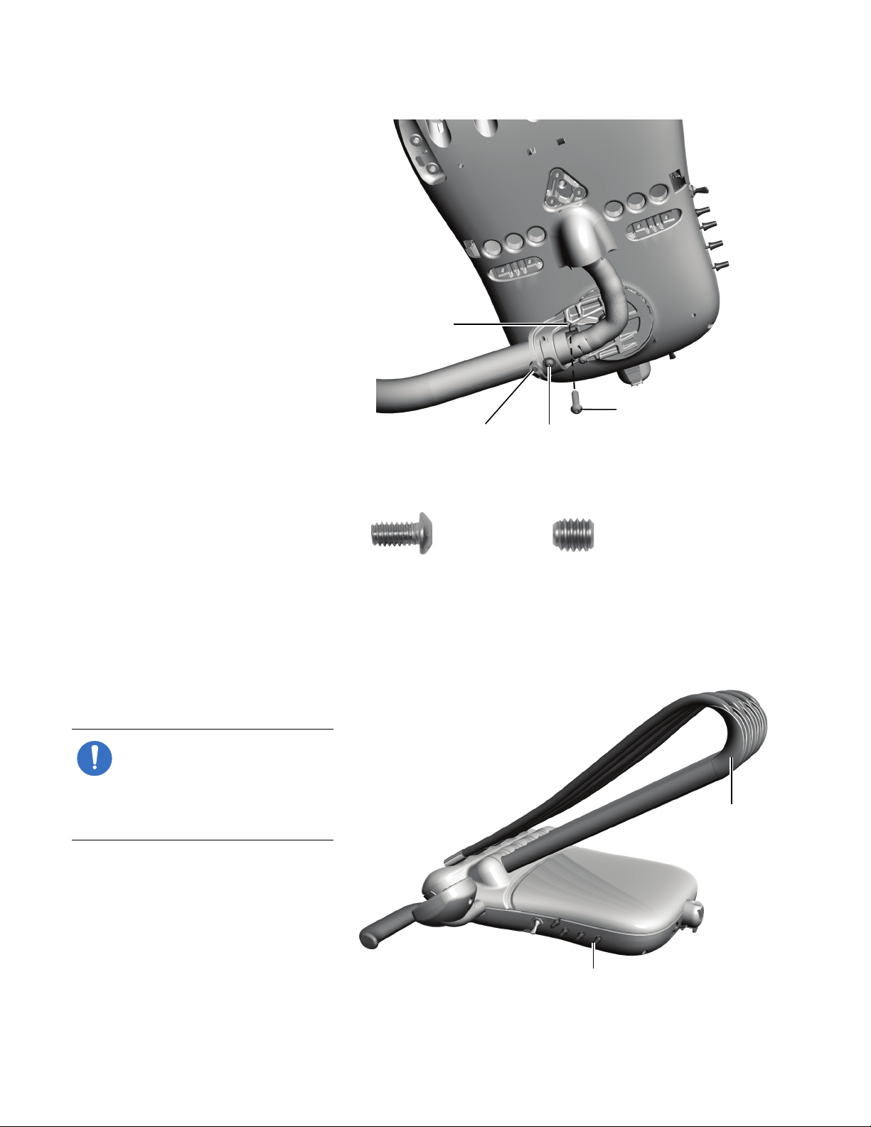
Install the Footswitch (Optional)
If the system contains a footswitch, complete
the following steps to install it.
1. From the rear of the chair, route the cord
to the chair’s circuit board and connect it
to the Touchpad Or Footswitch P5
connector on the chair circuit board.
2. Use a 3/16" hex key to secure the
footswitch cord in one of the side holes of
the strain relief.
NOTE If you are not installing any
modules on to the chair, go to
“Install Upholstery” on page 61.
Figure 11. Install the Footswitch
8 86.0087.00 Rev E
Page 9
I NSTALL THE
Chair-Base Mount
Use a 5/16" hex key driver to apply
30 ft-lb (4.15 m-kgs) of torque pressure.
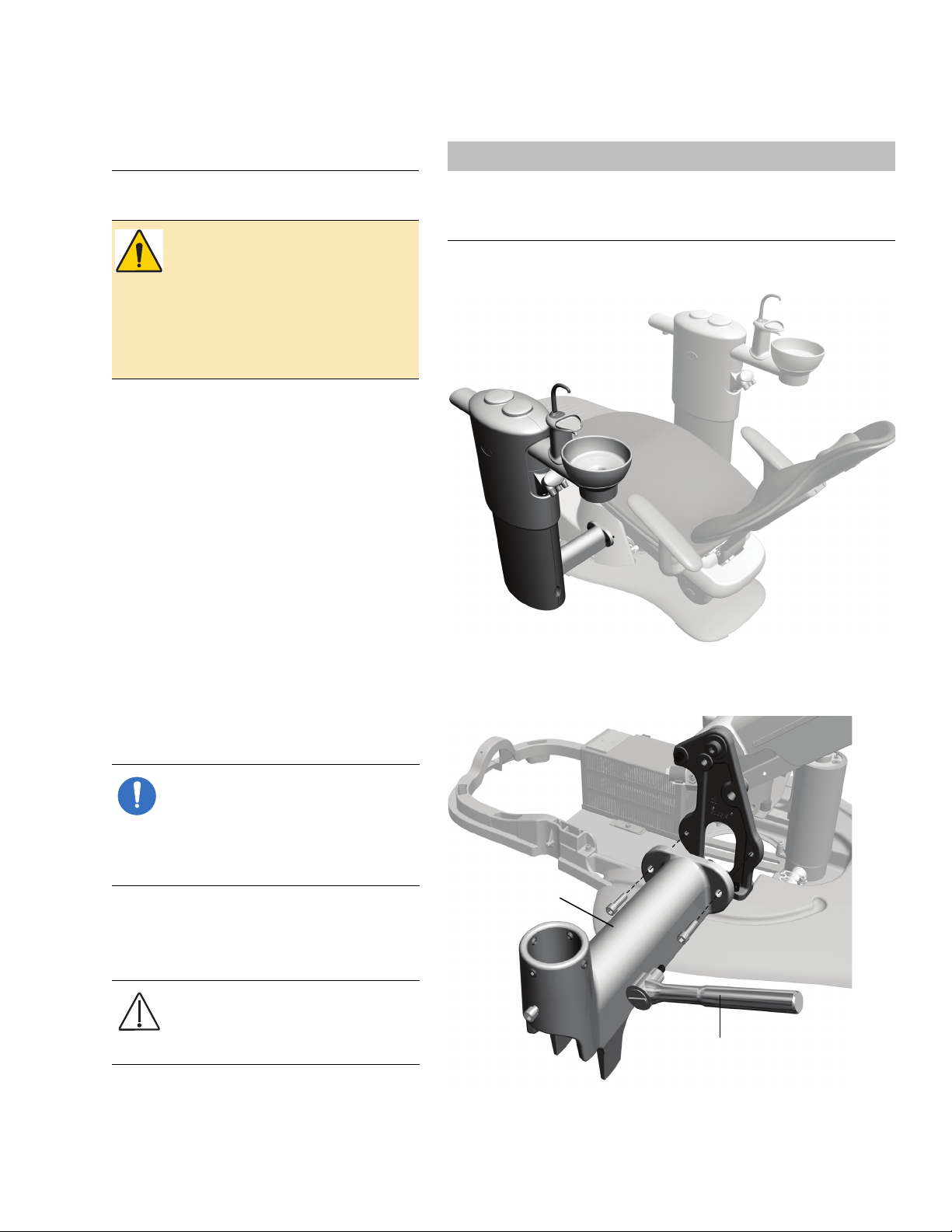
Install the Support Center
S UPPORT CENTER
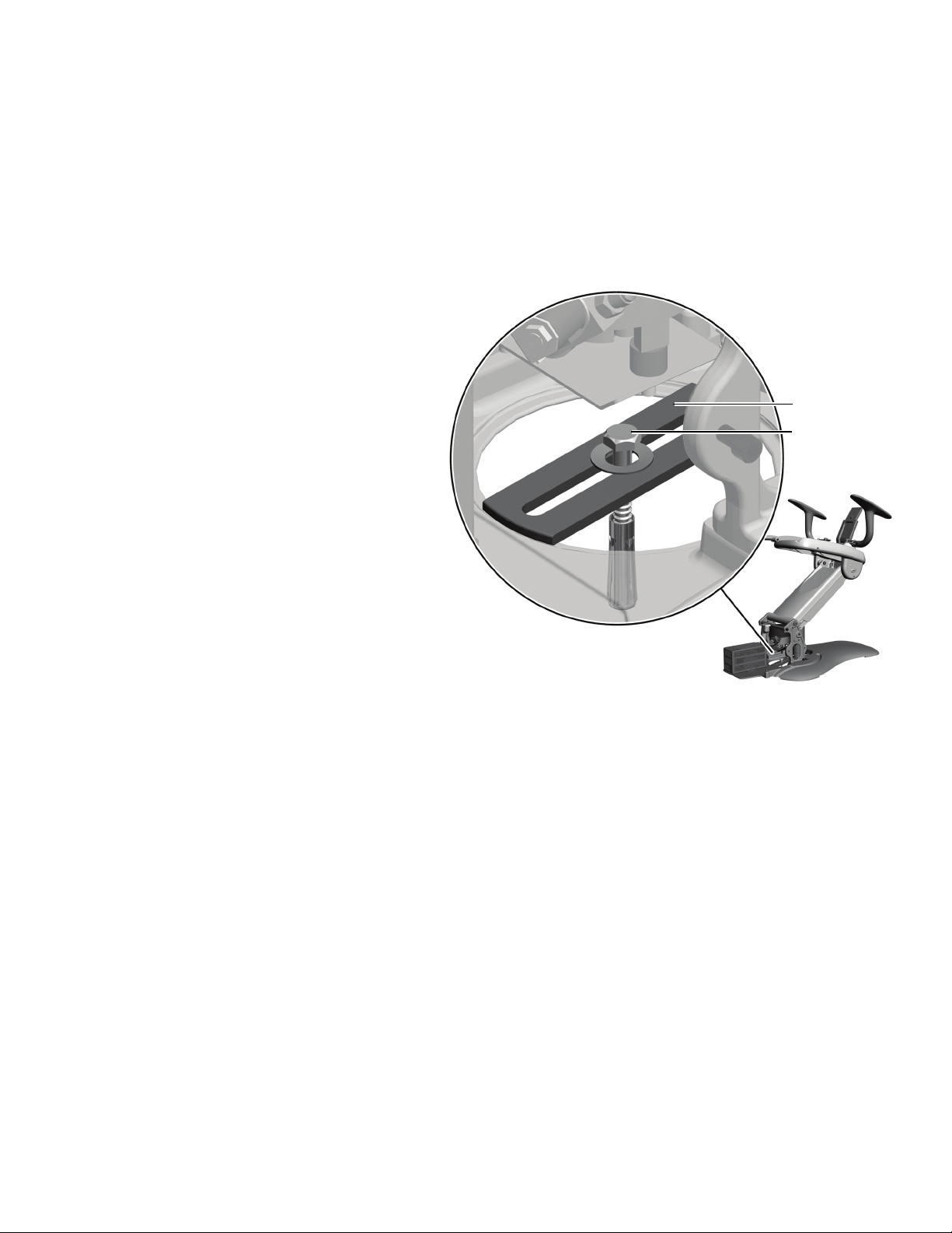
WARNIN G If the system includes a
cuspidor, do not remove the
positioning guide that is cable tied
to the cuspidor bowl support until
the support center is properly
aligned. Complete the following
section to ensure proper alignment
of the support center.
You can mount the support center on either
side of the chair. This section describes how
to install the support center and connect the
utilities.
Tools Needed For This Section
5/16" hex key driver 3/16" hex key
Level Diagonal cutters
Adjustable wrench Sleeve pusher
Figure 12. A-dec 361 Support Center and Cuspidor
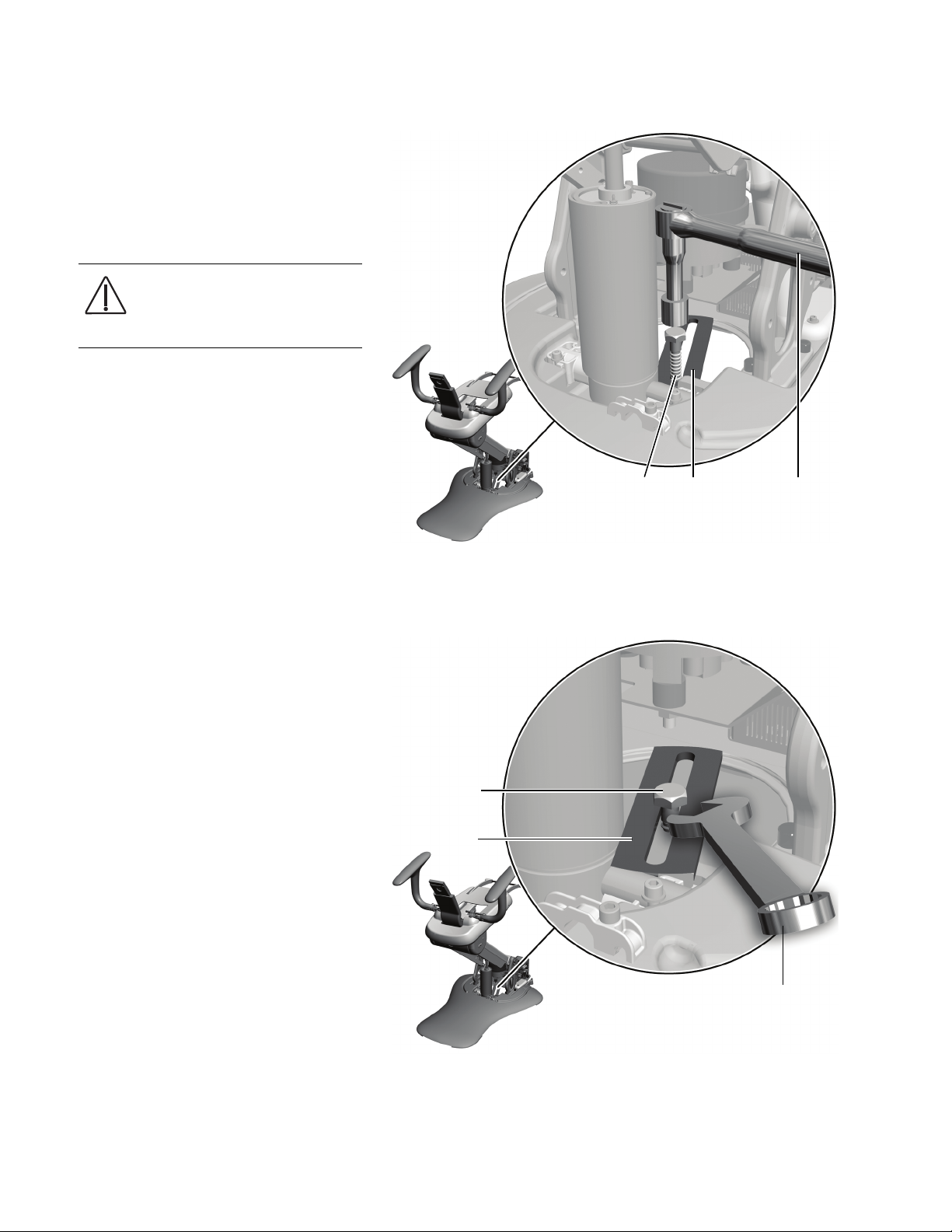
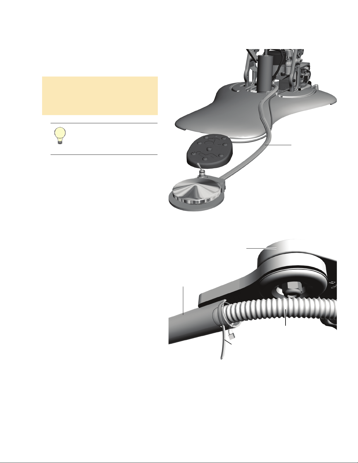
Install the Chair-Base Mount
NOTE If you have a post mount
system, skip this procedure and
follow the directions provided with
the chair adaptor kit. Then go to
“Install the Support Center Post” on
the next page.
Use a 5/16" hex key driver and two 1-1/2"
socket head screws to attach the chair-base
mount to the side of the chair frame.
CAUTION Be sure to tighten the
screws securely (approximately 30
ft-lb [4.15 m-kgs] of torque) so the
mount does not loosen during use.
Figure 13. Install the Chair-Base Mount
86.0087.00 Rev E
9
Page 10
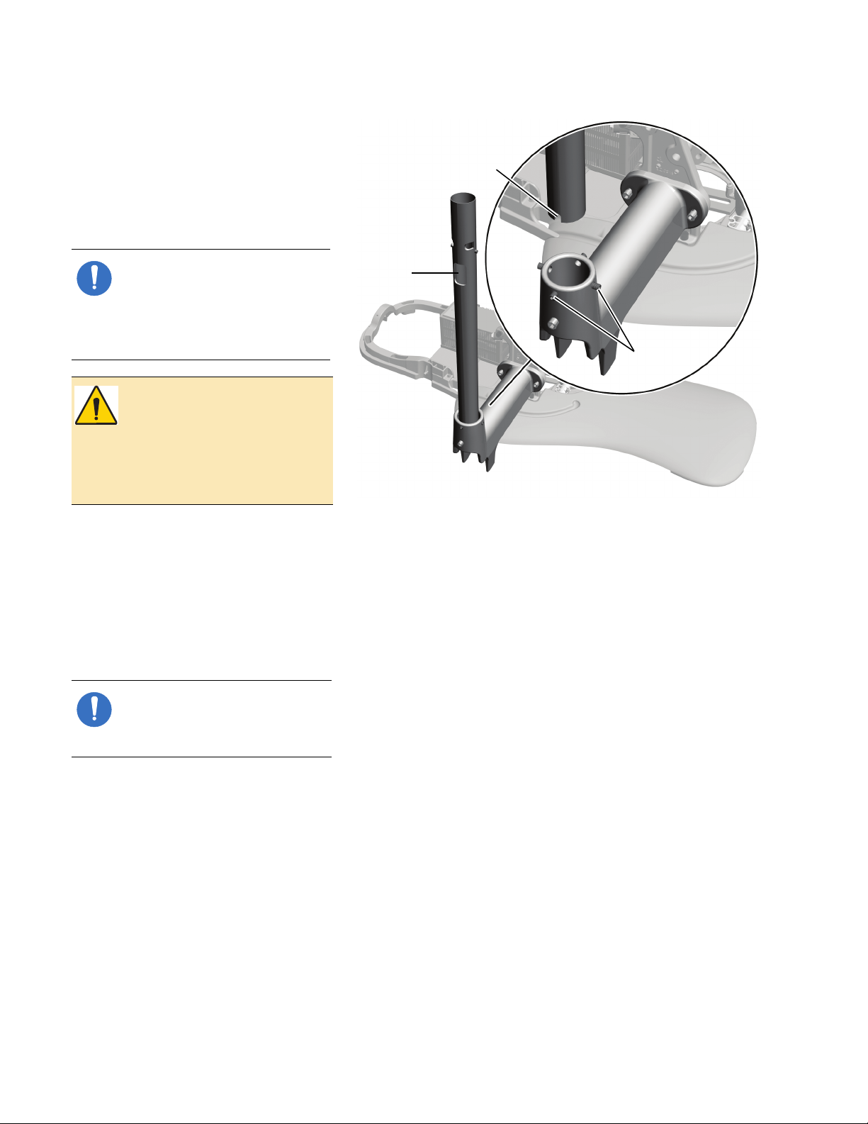
A-dec 300 System Installation Guide
Square
Hole
One Set Of
Leveling
Screws
Notch
Install the Support Center Post
1. Place the support center post in the chair-
base mount with the notched bottom
over the screw near the base of the
mount.
NOTE If you have a post mount
system, the support center post
installs into a chair adaptor
instead of the chair-base mount
and the post does not have
notches in the bottom.
WARNIN G If you’re installing a
post mount system, anchoring
the chair to the floor is required
for mechanical stability. Failure
to anchor properly could result
in damage, serious injury, or
death.
Figure 14. Install the Support Center Post
If the support center is installed to the
left of the patient, face the square hole
away from the chair. If the support center
is installed to the right of the patient, face
the square hole toward the chair.
2. Place a level vertically against the post
and align it with the four leveling screws
near the top of the chair-base mount.
NOTE If you have a post mount
system on an A-dec 511 chair, the
chair adaptor has eight leveling
screws.
10 86.0087.00 Rev E
Page 11
3. Use a 3/16" hex key to adjust the screws,
Support
Screw
switching from one set of leveling screws
to the other until the post is level. Always
align the level with the screws you are
adjusting.
4. Once the post is level, evenly tighten the
leveling screws to secure it.
NOTE This is the initial leveling of
the post. The system requires a final
level after everything is installed.
For final leveling instructions, see
“Level the System” on page 77.
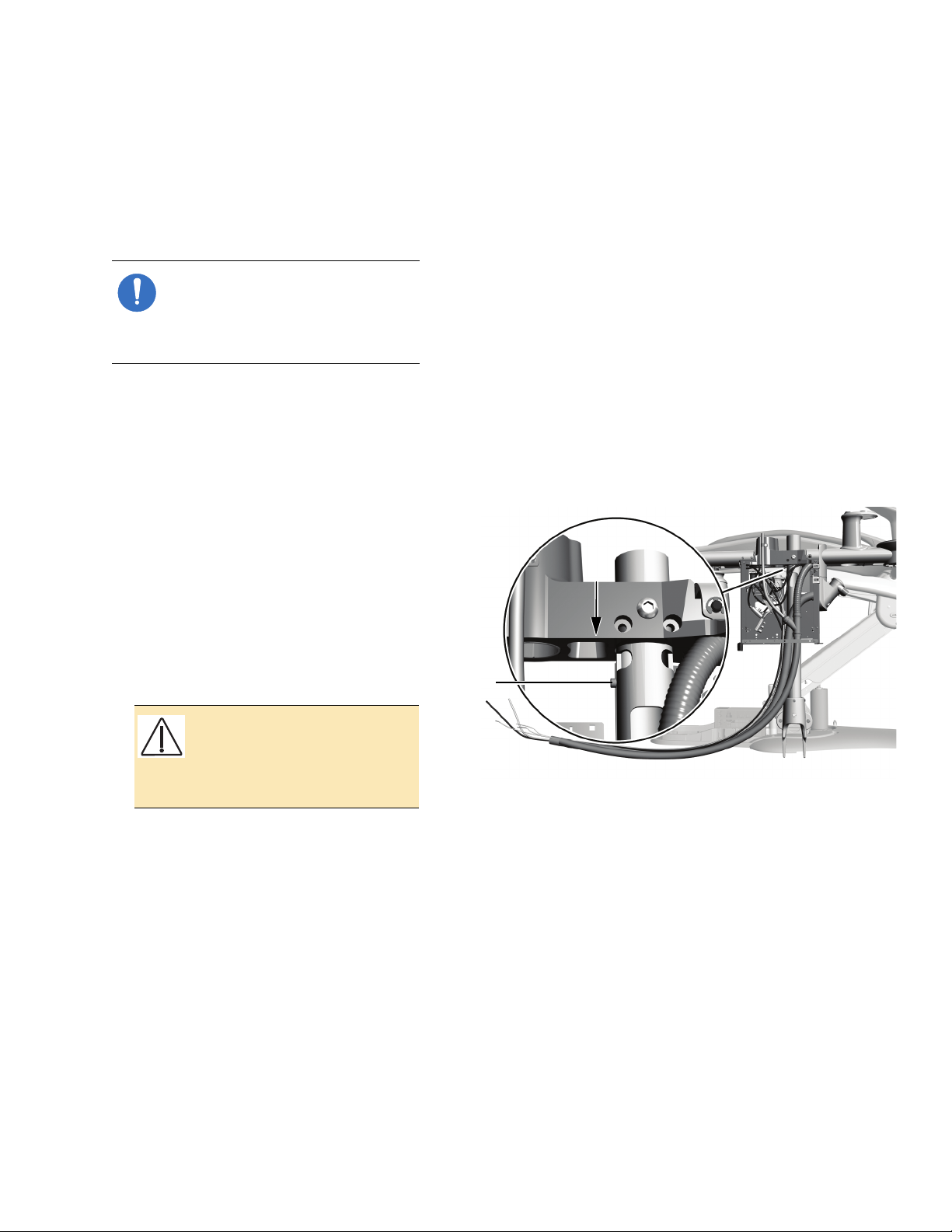
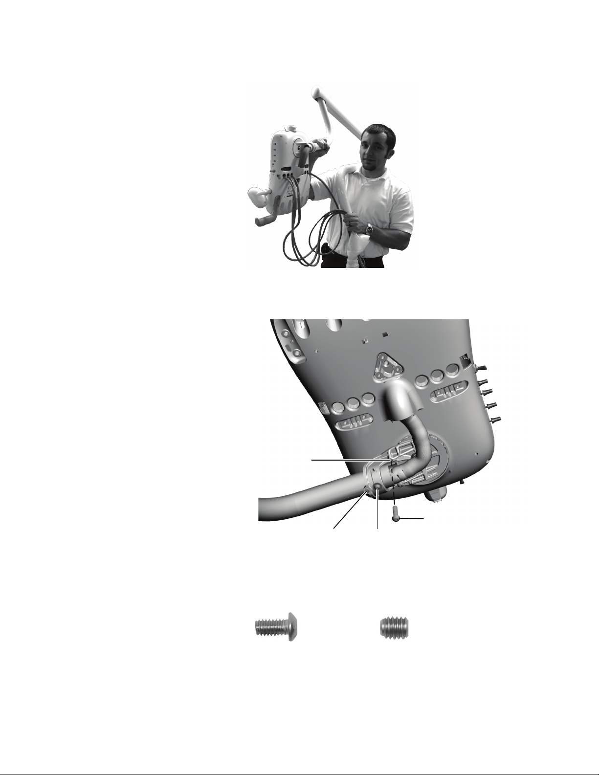
Install the Support Center
Install the Support Center
1. Wrap the support center tubing bundle
around your arm and lift the support
center out of the box.
2. Remove the covers from the support
center.
3. Place the support center over the support
center post with the water bottle
connection toward the toe of the chair.
CAUTION Be careful to clear all
wires and tubing so they stay on
the open side of the support
center frame and do not get
pinched or kinked.
4. Slide the support center down the post
until its frame rests on the support
screws on the support center post.
Figure 15. Position the Support Center
86.0087.00 Rev E
11
Page 12
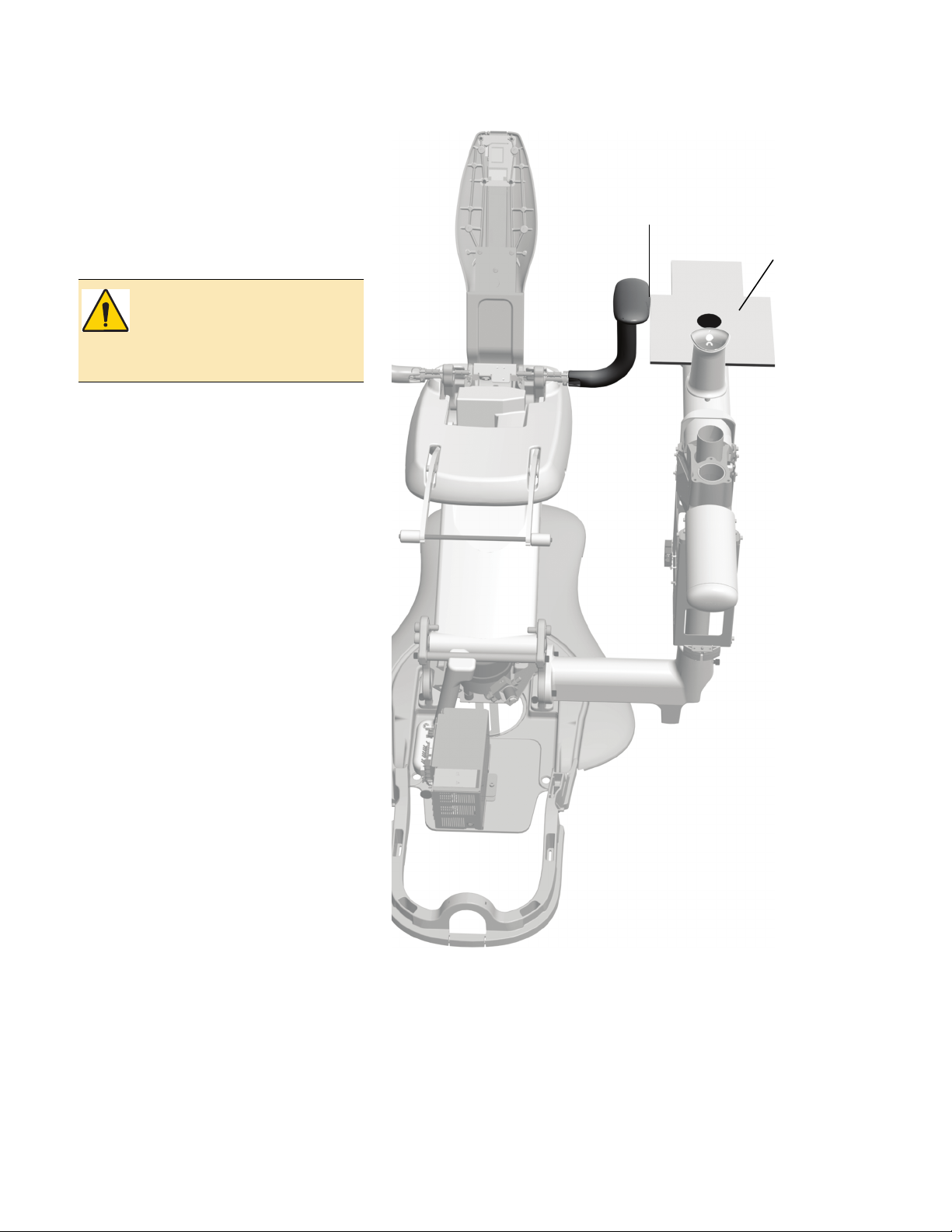
A-dec 300 System Installation Guide
Position ing
guide must
clear armrest.
Position ing
Guide
5. Align the support center depending on
the configuration of the system:
○ If you have an A-dec 300 system that
includes a cuspidor, align the support
center so the positioning guide clears
the armrest. Use the jumper and test
points to move the chair up and down
when testing clearance.
WARNIN G The positioning
guide must clear the armrest to
provide the proper clearance of
1-1/8" (29 mm) between the
cuspidor bowl and armrest.
○ If you have a base mount system
without a cuspidor, or a post mount
system, align the support center so it
is parallel to the dental chair.
Figure 16. Ensure the Positioning Guide Clears the Armrest
12 86.0087.00 Rev E
Page 13
Install the Support Center
Install two
1-1/2" Socket
Head Screws.
Button Head Screw
Use a 5/16" hex key driver to
apply 13 ft-lb (1.8 m-kgs) of
torque pressure to the screws.
Chair-Base Mount
Utilities Area
6. Use a 5/16" hex key driver to tighten the
button-head screw. While tightening the
screw, ensure the positioning guide
retains its clearance of the armrest.
CAUTION To ensure that the
button-head screw is properly
tightened, use approximately
13 ft-lb. (1.8 m-kgs) of torque.
NOTE If you have a post mount
system, you are finished
installing the support center.
Skip to the note after step 9 for
instructions on routing tubing
and wiring.
7. Use a 5/16" hex key driver to install each
of the two 1-1/2" socket head screws
until they are touching the back of the
holes in the support center post.
8. Alternately tighten both socket head
screws until they are firmly secure (use
approximately 13 ft-lb.
[1.8 m-kgs] of torque). While tightening
the screws, ensure the positioning guide
retains its clearance of the armrest.
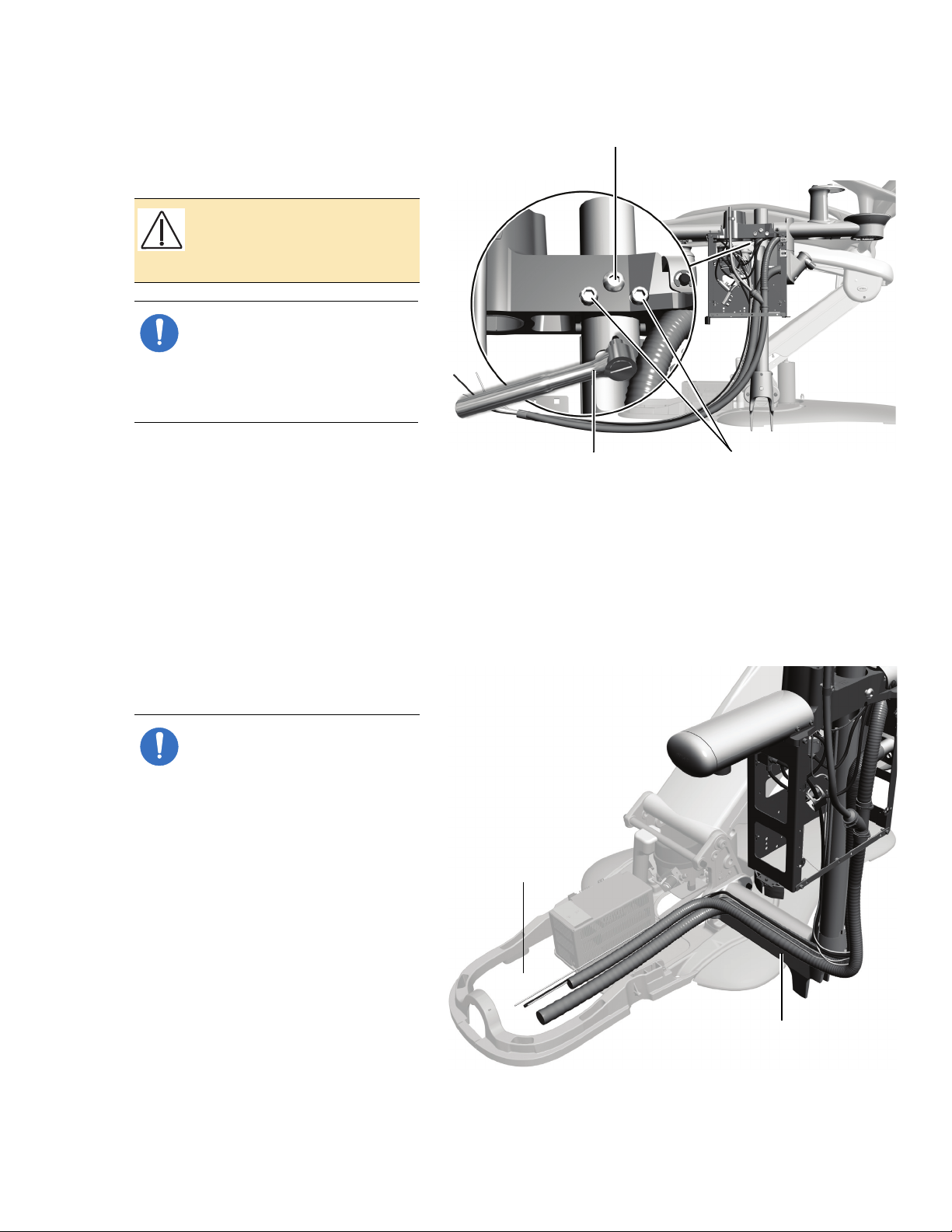
9. Route the support center tubing and
wiring through the chair-base mount into
the utilities area at the base of the chair.
Figure 17. Secure the Support Center
Figure 18. Route the Support Center Tubing Bundle
86.0087.00 Rev E
NOTE If you are installing a
post mount system, remove the
Y-connector from the data line
before routing the tubing. (The
Y-connector is provided to
connect to multiple data
communication system devices.)
Route the tubing and wiring
from the bottom of the support
center through the convolute
into the remote floor box.
If you are installing a post mount
system on an A-dec 511 chair,
13
Page 14
A-dec 300 System Installation Guide
1/2" (13mm)
Support
Center
Frame
Cuspidor
Ventilation
Tu be
separate the power cables and
data line from the tubing group
and route them from the support
center, underneath the mount,
and down the lift arm to the
power supply. Route the rest of
the tubing bundle through the
convolute into the remote floor
box.
For information about installing
the remote floor box, see “Install
the Remote Floor Box” on
page 39.
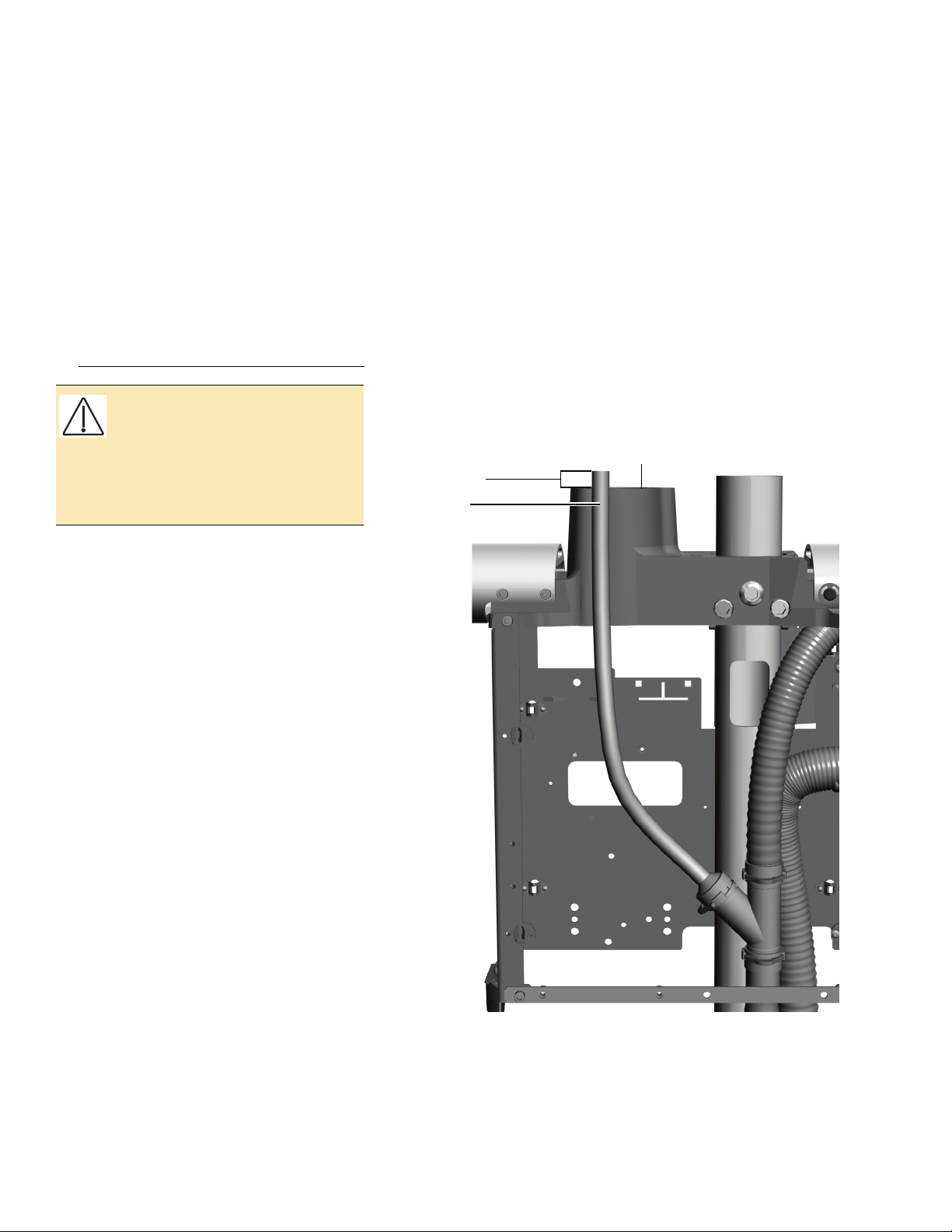
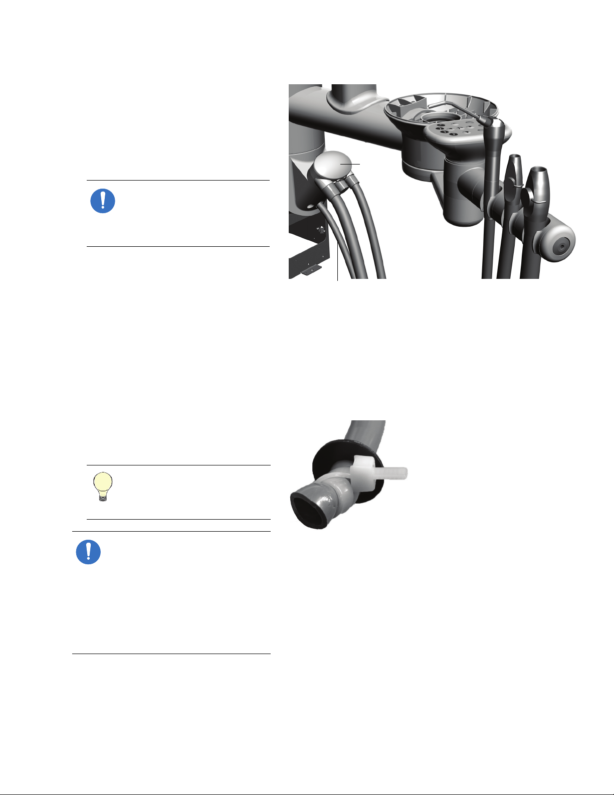
CAUTION Once you’ve completed
installing the support center, verify
that the end of the cuspidor
ventilation tube is 1/2" (13 mm)
above the support center frame.
This ensures that the cuspidor
drains properly.
Install the Moisture Separator (Optional)
To install the moisture separator, use the
directions included in the moisture
separator kit (p/n 41.1477.00); then see
“Connect the Utilities” on page 40.
Figure 19. Verify the Cuspidor Ventilation Tubing Position
14 86.0087.00 Rev E
Page 15

I NSTALL THE
A-dec 352 Telescoping
Assistant’s Instrumentation
with Optional Touchpad
A-dec 351 Radius-Style
Assistant’s Instrumentation
with Touchpad
A-dec 353
Cuspidor-Mounted
Assistant’s Instrumentation
with Optional Touchpad
SSISTANT' S
A
Install the Assistant's Instrumentation
I NSTRUMENTATION
Assistant’s instrumentation can be mounted
three ways.
Radius
Cuspidor-Mounted (353) . . . . . . . . . . 18
Telescoping (352) . . . . . . . . . . . . . . 20
®
-Style (351) . . . . . . . . . . . . . 16
Figure 20. Assistant’s Instrumentation
86.0087.00 Rev E
15
Page 16
A-dec 300 System Installation Guide
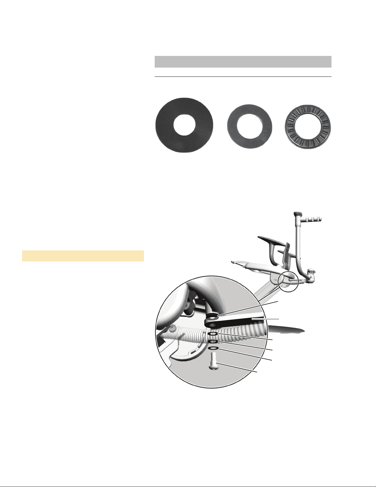
Flat Washer Bearing
Nylatron Washer
Flat Washer
Bearing
Flat Washer
Assistant’s
Instrumentation Arm
Nylatron Washer
Screw
Install a Radius-Style Assistant’s Instrumentation (351)
Install the Assistant’s Instrumentation Arm
1. Slide the bearing and two washers from
the kit onto the screw.
2. Insert the screw through the hole in the
assistant’s instrumentation arm.
3. Slide the Nylatron
screw.
®
washer onto the
Tools Needed For This Section
Hex key set
Figure 21. Types of Washers Used
Figure 22. Install the Assistant’s Instrumentation Arm
4. Put Loctite® on the end of the screw.
5. Use a 1/4" hex key to securely tighten the
arm to the chair. The arm should rotate
smoothly and not drift.
6. Place the syringe in its holder on the
assistant’s instrumentation.
7. Place the high volume evacuation (HVE)
and saliva ejector in their holders; then
attach their tubing to the vacuum
canister.
16 86.0087.00 Rev E
Page 17
Install the Assistant's Instrumentation
Overflow
Bottle
Plate
Loosen
Middle
Screw
Notch
To p
Mount
Screw
Tu bi ng
and
Cables
Vacuum
Line
Clear
Hydraulic
Line
Cable Tie
to These
Blocks
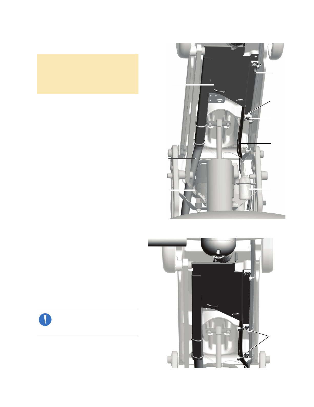
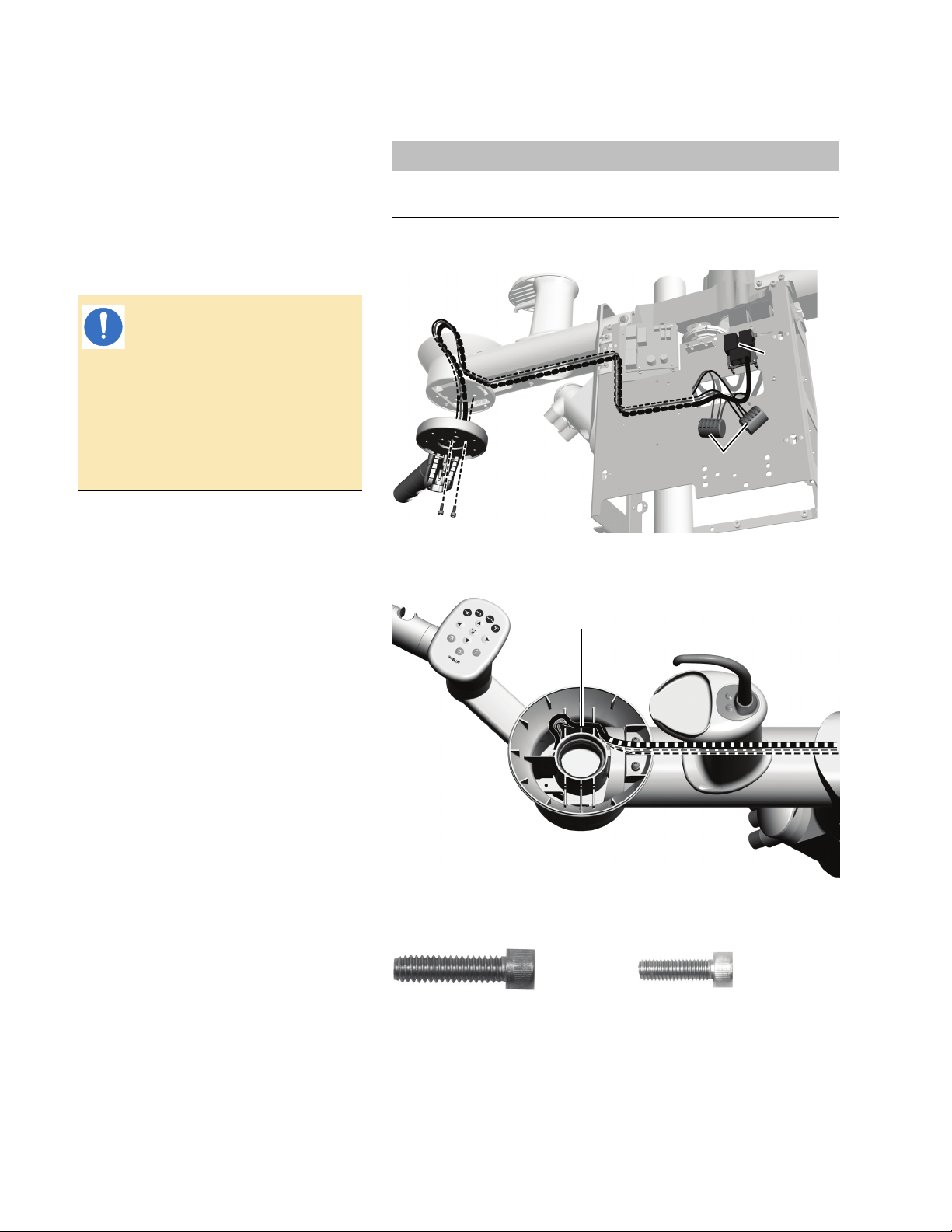
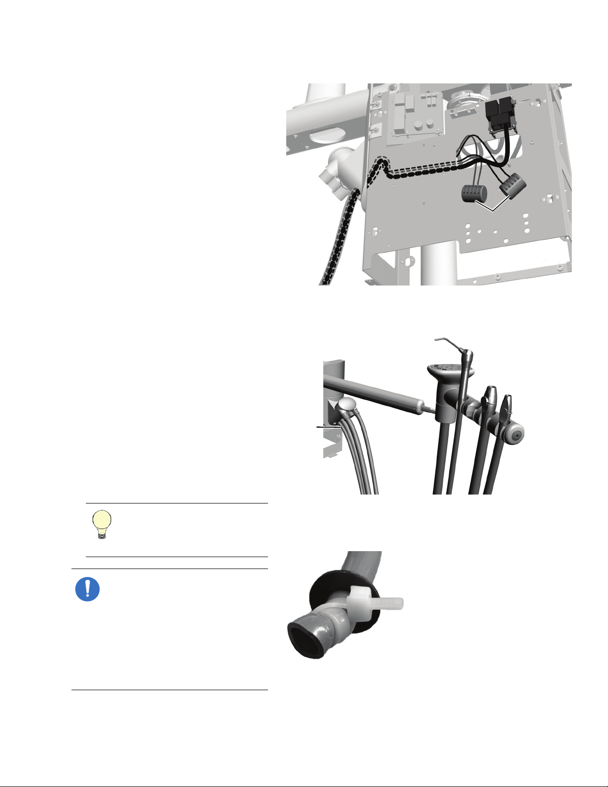
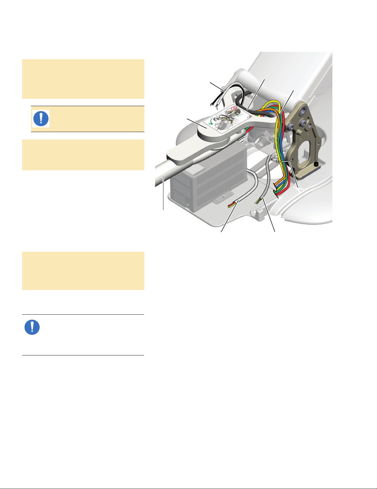
Route the Tubing, Cables, and Lines
1. From the back of the chair, route the
vacuum line to the left of the lift cylinder
and above the clear hydraulic tubing.
2. Route the tubing, power cables, and data
line to the right of the lift cylinder and
above the overflow bottle.
3. Use a 3/16" hex key to loosen the socket
head screw securing the middle white
mounting block.
4. Remove the top screw and mounting
block.
5. Slide the notch in the plate between the
middle mounting block and the lift arm.
6. Replace the top screw and mounting
block. Make sure the screw is securely
tightened.
7. Tighten the middle socket head screw.
Figure 23. Install the Assistant’s Instrumentation Plate
8. Cable tie the tubing, power cables, and
data line to the bottom two mounting
blocks.
Figure 24. Cable Tie the Tubing and Wires
9. Route the syringe tubing between the
motor pump and the wire cover, then
behind the power supply.
10.Route the power cables and data line to
the chair circuit board.
NOTE If the system does not
include other modules, go to “Install
the Contoured Floor Box” on
page 37.
86.0087.00 Rev E
17
Page 18
A-dec 300 System Installation Guide
WAGO
Connectors
Data
Ports
Data Line and Power Cable
Fit in Cuspidor Grooves
1/4-20 x 1" - Goes in
the Middle Hole
10-32 x 5/8" - Goes in
the Recessed Hole
Install a Cuspidor-Mounted Assistant’s Instrumentation (353)
1. Use diagonal cutters to cut the cable tie
and remove the positioning guide.
NOTE Save the positioning
guide and the foam plug holding
it in the cuspidor bowl support.
You will need it later to verify
proper clearance between the
cuspidor bowl and armrest. For
more information, see “Verify
Proper Clearance Between the
Cuspidor Bowl and the Armrest”
on page 94.
2. If the system includes an AVS, use a 1/8"
hex key to remove the two screws
connecting the toggle assembly to the
bottom of the cuspidor bowl support.
3. If the assistant's instrumentation includes
a touchpad, route the power cable and
data line up through the cuspidor holder.
For the wires to fit properly, place the
power cable into the grooves first then
the data line.
4. Place the assistant's instrumentation
under the cuspidor holder and angle it
away from the chair so that the post fits
into the hole in the bottom of the
cuspidor bowl support.
5. To attach the assistant’s instrumentation
to the bottom of the cuspidor holder, use
a 3/16" hex key to install the 1/4-20 x 1"
screw in the middle and a 5/32" hex key
to install the 10-32 x 5/8" screw in the
large recessed hole that is off center.
6. If you disconnected the AVS toggle
assembly in step 2, reconnect it now.
Tools Needed For This Section
Diagonal cutters Sleeve pusher
Hex key set
Figure 25. Routing with a Touchpad Viewed From Below
Figure 26. Routing with a Touchpad Viewed From Above
Figure 27. Socket Head Screws (Actual Size Shown)
18 86.0087.00 Rev E
Page 19
Install the Assistant's Instrumentation
Vacuum
Canister
Syringe
Tu bi ng
7. If the system includes a touchpad, route
the data line and power cable through
the support center (see Figure 25 on
page 18).
8. Place the high volume evacuation (HVE)
and saliva ejector in their holders; then
attach their tubing to the vacuum
canister.
NOTE If the system includes an
AVS, the HVE and saliva ejector
are installed before the product
is shipped and cannot be
removed.
9. Place the syringe in the holder and route
its tubing under the vacuum canister
through the center hole.
Figure 28. Route the HVE, Saliva Ejector, and Syringe Tubing
10.Use a cable tie and a washer to create a
strain relief for the syringe tubing. Make
a double loop with the cable tie to firmly
hold the tubing.
TIP When setting the strain
relief, leave enough tubing to
match the drape of the
instrument tubing.
NOTE If the system does not
include other modules, go to the
section for the system’s
configuration:
• Base Mount System - “Install the
Contoured Floor Box” on
page 37
• Post Mount System - “Install the
Remote Floor Box” on page 39
Figure 29. Install the Strain Relief for the Assistant’s Syringe
86.0087.00 Rev E
19
Page 20
A-dec 300 System Installation Guide
Stop
Toe of the Chair
Wave Washer
Assistant’s
Holder
Assembly
Sheath
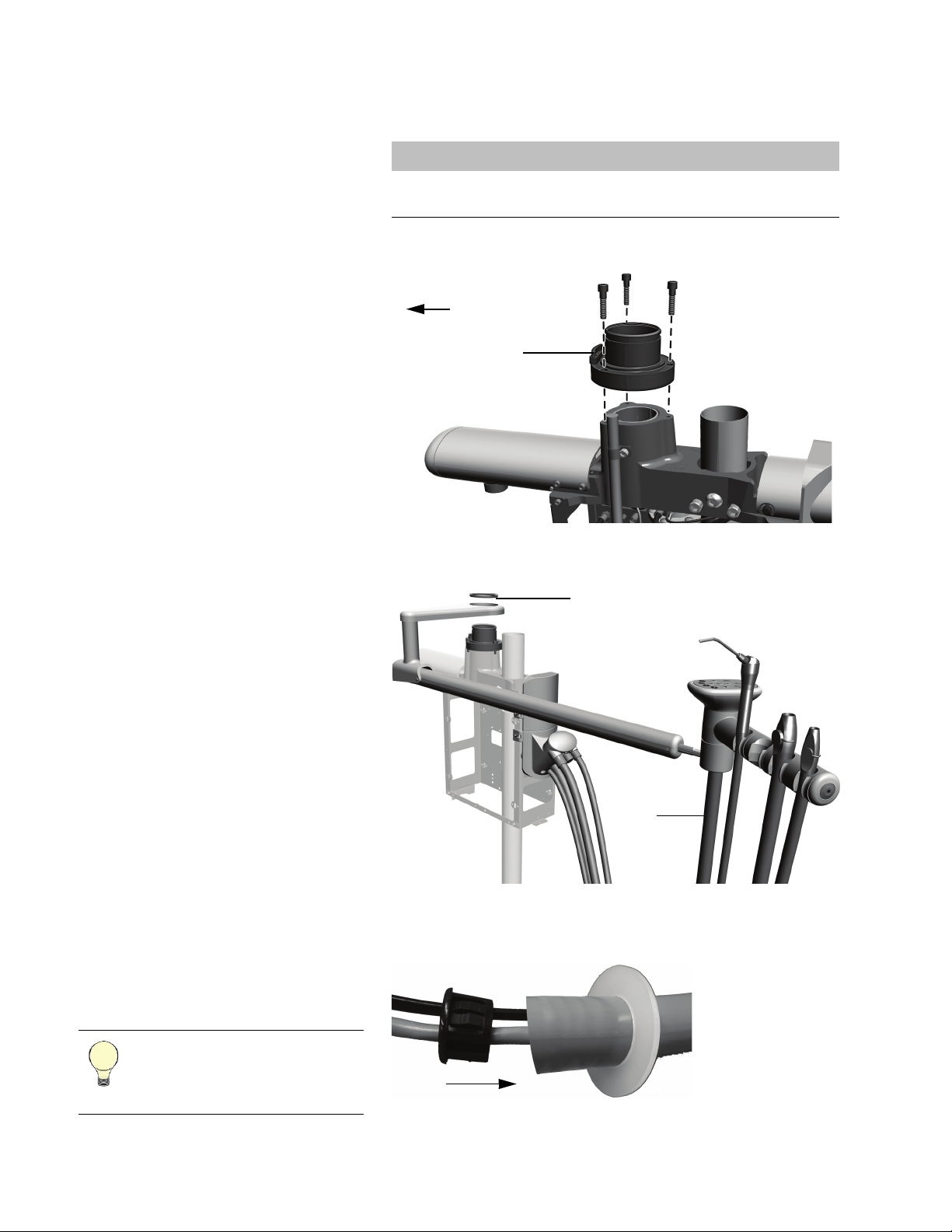
Install an Assistant’s Instrumentation Mounted on a Telescoping Arm (352)
1. Use a 3/16" hex key and three 1" socket
head screws to mount the hub for the
telescoping arm on the support center.
The stop on the hub goes toward the toe
of the chair.
2. Push the sheath onto the barb on the
bottom of the assistant’s holder
assembly.
3. Set the assistant’s arm on the hub.
4. Push down one end of the wave washer
and catch it on the hub ridge. Continue
to work systematically around the hub to
push the washer down until it is
completely installed.
5. Place the HVE and saliva ejector in their
holders; then attach their tubing to the
vacuum canister.
6. If the system includes a touchpad:
(1) Route the touchpad tubing under the
vacuum canister through the hole on
the right (it is the largest hole).
Tools Needed For This Section
3/16" hex key Sleeve pusher
Diagonal cutters
Figure 30. Install the Telescoping Arm Hub
Figure 31. Install the Telescoping Arm
Figure 32. Install the Strain Relief for the Touchpad Tubing
(2) Install the strain relief by placing the
washer on the tubing then inserting
the bushing into the tube.
TIP When setting the strain
relief, leave enough tubing to
match the drape of the
instrument tubing.
20 86.0087.00 Rev E
Page 21
Install the Assistant's Instrumentation
WAGO
Connectors
Syringe
Tu bi ng
(3) Route the data line and power cables
through the support center.
7. Place the syringe in the holder and route
its tubing under the vacuum canister
through the center hole (see Figure 31 on
page 20).
Figure 33. Route the Data Line and Power Cables
Figure 34. Route the Syringe Tubing
8. Use a cable tie and a washer to create a
strain relief for the syringe tubing. Make
a double loop with the cable tie to firmly
hold the tubing.
TIP When setting the strain
relief, leave enough tubing to
match the drape of the
instrument tubing.
NOTE If the system does not
include other modules, go to the
section for the system’s
configuration:
• Base Mount System - “Install the
Contoured Floor Box” on
page 37
• Post Mount System - “Install the
Remote Floor Box” on page 39
Figure 35. Install the Strain Relief for the Assistant’s Syringe
86.0087.00 Rev E
21
Page 22
A-dec 300 System Installation Guide
A-dec 335 Continental Delivery System
mounted on a Support Center
A-dec 332 Radius-Style Traditional Delivery System
I NSTALL THE D ELIVERY SYSTEM
The A-dec 300 system can be configured
with a Traditional or Continental delivery
system. The installation steps are the same
for both of them.
Delivery systems can be Radius-style or
mounted on a support center.
Radius-Style (332 & 333) . . . . . . . . . . 23
Support Center Mounted (354 & 335) . 29
Figure 36. Delivery Systems
22 86.0087.00 Rev E
Page 23
Install a Radius-Style
Cable
Tie
Post
Clear Tubing
Install the Delivery System
Delivery System
(332 & 333)
Install the Rigid Arm
1. Raise the chair all the way up.
2. Turn off the power.
3. Cut the cable tie holding the clear
hydraulic tubing that goes from the lift
cylinder to the motor pump.
4. Push the tubing back so that it is behind
the post on the chair tower.
Tools Needed For This Section
Hex key set Diagonal cutters
Sleeve pusher Adjustable wrench
Tape measure
Figure 37. Prepare the Chair Tower
86.0087.00 Rev E
23
Page 24
A-dec 300 System Installation Guide
Chair
To we r
Front Mount Casting
Post
Clear Hydraulic Tubing
Positioned Between the Post
and Axle for the Link Arm
Mount Bolts
Notches
5. Place the notches in the front mount
casting over the posts on the chair
towers.
CAUTION Make sure all tubing
and wiring are away from the
posts so they do not get pinched.
6. While holding the rigid arm in place,
install the front bolt then the back bolt on
one side and finger tighten.
7. Install the bolts on the other side; then
use a 5/16" hex key to securely tighten all
bolts.
Figure 38. Install the Rigid Arm
24 86.0087.00 Rev E
Page 25
Install the Delivery System
Mount Screw
Water Bottle
Housing
Rigid Arm
Hole
Flexarm
Rigid Arm
Tubing Bundle
Tr i m R i n g
Install the Water Bottle
1. Use a 1/8" hex key to loosen the screw
below the hole in the rigid arm.
2. Route the water bottle tubing into the
hole, through the arm and out the
bottom.
3. Slide the water bottle housing down over
the mount screw and secure it to the arm.
Figure 39. Install the Water Bottle
Install the Flexarm and Control Head
1. Cut the cable tie holding the trim ring to
the delivery system tubing bundle.
2. Remove the delivery system from the
box and balance it over your shoulder,
with the control head in back of you, so
one hand is free to route the tubing
bundle.
3. Route the delivery system tubing bundle
down through the rigid arm.
TIP To keep Traditional delivery
system handpiece tubing out of
the way, wrap them around the
control head before installing the
flexarm.
4. Insert the flex arm into the rigid arm
until it is fully seated.
Figure 40. Install the Flexarm
86.0087.00 Rev E
25
Page 26
A-dec 300 System Installation Guide
Install and Tighten
1/4-20 x 1/2"
Leveling Screw
Loosen
Button Head
Screw
Hole for Missing
Leveling Screw
Install 3/8"
Setscrew
1/4-20 x 1/2"
Leveling Screw
5/16-18 x 3/8"
Setscrew
Adjustment Key
Whip Hook
5. Use a 5/32" hex key to loosen the
button-head screw that holds the control
head’s position.
6. Rotate the control head so it is positioned
over the hole for the missing leveling
screw.
7. To hold the control head in place, use a
5/32" hex key to install and tighten the
1/4-20 x 1/2" leveling screw.
8. Use a 5/32" hex key to install the 3/8"
setscrew.
Figure 41. Install the Control Head
Figure 42. Leveling and Setscrews (Actual Size Shown)
9. Place the handpiece tubing in their
holders and insert the adjustment keys
into their holes on the side of the control
head.
26 86.0087.00 Rev E
NOTE If you are installing a
Continental delivery system,
insert the whip hooks into the
whips. The top ends of the
whip hooks face the front of the
control head.
Figure 43. Insert Whip Hooks and Adjustment Keys
Page 27
Install the Delivery System
Tubing Ridges
Face Up
Convolute
Secure with Cable Tie
Rigid Arm
Front Mount Casting
Route the Tubing and Wiring
1. From the back of the chair, route the
foot control tubing over the strain relief
and behind the power supply.
2. Measure three feet of the water bottle
tubing from where it comes out of the
rigid arm. Cut off the excess.
3. Strip the sheath around the water bottle
tubing back to the rigid arm.
TIP Mark the ends of the water
bottle tubing to distinguish them
from the delivery system tubing
when connecting the utilities.
4. Route both the water bottle and delivery
system tubing bundles through the
convolute (see Figure 45).
Figure 44. Route the Foot Control Tubing
5. Form a loop with a cable tie through the
two holes in the rigid arm.
6. Push the convolute about an inch (a few
centimeters) through the loop into the
rigid arm.
7. Tighten the cable tie to secure the
convolute.
Figure 45. Route the Tubing Bundles Through the Convolute
86.0087.00 Rev E
27
Page 28
A-dec 300 System Installation Guide
Water
Bottle and
Delivery
System
Tubi n g
Power Cabl es
and Data Line
Assistant’s Syringe
Tu b in g
Rigid Arm
Straight Out
Cable Tie
Front Mount
Hydraulic
Tubi n g
Foot Control
Tu bi ng
8. Remove the tape from the ends of the
water bottle and delivery system tubing.
9. Route the water bottle and delivery
system tubing up through the front
mount (be sure to go behind the black
hydraulic tubing) then down to behind
the power supply.
NOTE Improper routing of the
tubing can hinder the movement
of the delivery system rigid arm.
10.Route the delivery system power cables,
ground wire, and data line up through
the front mount and down to the chair
circuit board on the power supply.
11.If the system includes an assistant’s
instrumentation, route its syringe tubing
around the lift cylinder to behind the
power supply.
Arrange the Tubing
Figure 46. Route the Tubing and Wires
1. Position the rigid arm so that it is
2. Neatly gather the tubing. Cable tie it to
straight out from the middle of the chair,
in line with the front mount.
the chair tower.
NOTE If the system includes a tray
holder, see “Install the Tray Holder
(Optional)” on page 32. If not, go to
“Install the Contoured Floor Box”
on page 37.
28 86.0087.00 Rev E
Page 29
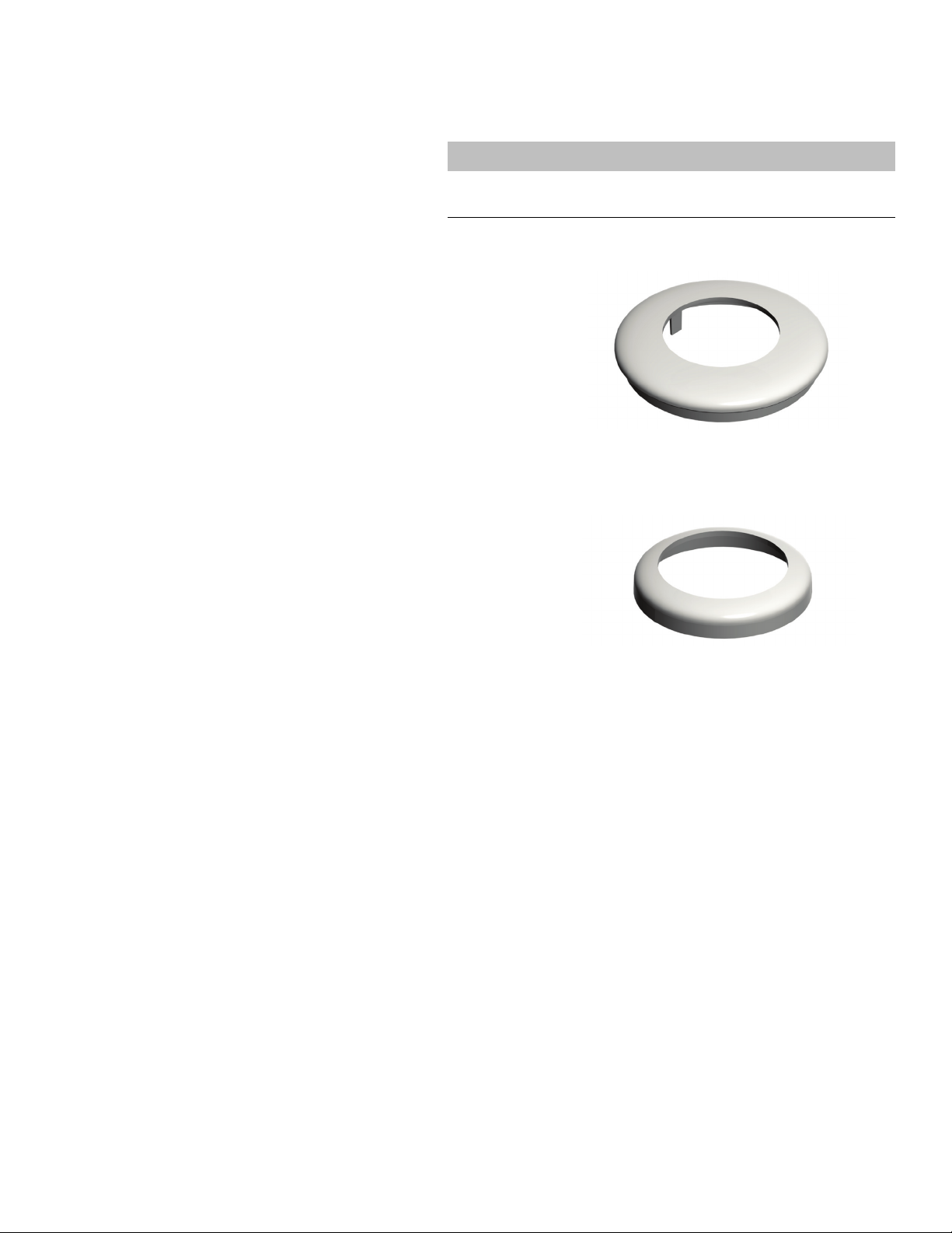
Install a Delivery System
This trim ring
ships on the
delivery system
post.
This trim ring
ships in the
assistant’s
instrumentation
box.
Trim Ring Used With Delivery System
Trim Ring Used With Delivery System and
Assistant’s Instrumentation Mounted on a
Telescoping Arm
Install the Delivery System
Mounted on a Support
Center (334 & 335)
Install the Components
1. Lower the chair. Turn off the power.
2. Ensure the correct trim ring is on the
delivery system post.
○ If the system includes a delivery
system but no assistant’s
instrumentation mounted on a
telescoping arm, use the top trim ring
in Figure 47.
○ If the system includes a delivery
system and assistant’s
instrumentation mounted on a
telescoping arm, use the bottom trim
ring in Figure 47.
Tools Needed For This Section
Hex key set Diagonal cutters
Adjustable wrench Sleeve pusher
Figure 47. Delivery System Post Trim Rings
86.0087.00 Rev E
29
Page 30
A-dec 300 System Installation Guide
Install and Tighten
1/4-20 x 1/2"
Leveling Screw
Loosen
Button Head
Screw
Hole For Missing
Leveling Screw
Install 3/8"
Setscrew
1/4-20 x 1/2"
Leveling Screw
3/8"
Setscrew
3. Remove the delivery system from the
box and balance it over your shoulder so
one hand is free to route the tubing
bundle.
The delivery system post inserts into the
support center in the post hole toward
the toe of the chair.
4. Route the tubing bundle into the support
center then insert the delivery system
post into the support center until it is
fully seated.
5. Use a 5/32" hex key to loosen the
button-head screw that holds the control
head’s position.
6. Rotate the control head so it is positioned
over the hole for the missing leveling
screw.
Figure 48. Carry the Delivery System
Figure 49. Install the Control Head
7. To hold the control head in place, use a
5/32" hex key to install and tighten the
1/4-20 x 1/2" leveling screw.
8. Use a 5/32" hex key to install the 3/8"
setscrew.
30 86.0087.00 Rev E
Figure 50. Leveling and Setscrews (Actual Size Shown)
Page 31

Install the Delivery System
Adjustment Key
Whip Hook
Tubing Ridges Face Up
9. Place the handpiece tubings in their
holders and insert the adjustment keys
into their holes on the side of the control
head.
NOTE If you are installing a
Continental delivery system, insert
the whip hooks into the whips. The
top ends of the whip hooks face the
front of the control head.
Route the Foot Control Tubing
1. Raise the chair all the way up.
2. From the back of the chair, route the
foot control tubing through the chairbase mount and up into the support
center.
Figure 51. Insert Whip Hooks and Adjustment Keys
Figure 52. Route the Foot Control Tubing
NOTE If you have a post mount
system, the foot control tubing
routes through a hole in the
bracket in the bottom of the
support center that holds the
convolute.
If the system includes a tray holder,
see “Install the Tray Holder
(Optional)” on the next page. If not,
go to the section for the system
configuration:
• Base Mount System - “Install the
Contoured Floor Box” on page 37
• Post Mount System - “Install the
Remote Floor Box” on page 39
86.0087.00 Rev E
31
Page 32

A-dec 300 System Installation Guide
Tra y Mo u n t
Location
Install the Tray Holder (Optional)
To install the tray holder, select the type of
delivery system and complete the steps.
Continental Delivery System
Use a 5/32" hex key and three 10-32 x 3/4"
screws to attach the mount arm to the
middle of the bottom of the control head.
Figure 53. Tray Mount Position on a Continental Control Head
32 86.0087.00 Rev E
Page 33

Install the Delivery System
Tr a y H o l d e rMount Arm
When installing a large tray holder, face the four screw holes in
the mount away from the side of the control head.
Mount
Four
Screw
Holes
Tr a y M o u n t
Locations
When installing a small tray holder, face the four screw holes in
the mount toward the front of the control head.
Tra y
Holder
Mount
Arm
Mount
Four
Screw
Holes
Tra y Mo u n t
Locations
Traditional Delivery System
NOTE Large tray holders attach to
mount arms in a different
orientation than small tray holders.
For proper orientation, see Figure 54
and Figure 55.
1. Use a 1/8" hex key and the 10-32 x
1/2" screws to attach the bottom of the
tray holder to the mount arm.
CAUTION Do not over tighten
the screws or you may damage
the surface of the tray or break
the mount.
2. Use a 1/8" hex key and two 10-32 x
1" button head screws to attach the
mount arm to the side of the bottom of
the control head.
TIP While the tray holder can be
installed on either side of the
control head, it is helpful to
mount it on the side opposite of
the adjustment keys to provide
better access to the keys.
Figure 54. Install a Large Tray Holder
Figure 55. Install a Small Tray Holder
NOTE If the system does not
include other modules, go to the
section for the system’s
configuration:
• Base Mount System - “Install the
Contoured Floor Box” on
page 37
• Post Mount System - “Install the
86.0087.00 Rev E
Remote Floor Box” on page 39
33
Page 34

A-dec 300 System Installation Guide
Connect
Wires
Tr i m C o v e r
Plastic
Bearing
Intermediate
Post
Light Post
Chair-Base
Mount
Tri m Ri n g
Plug
Chair
Circuit
Board
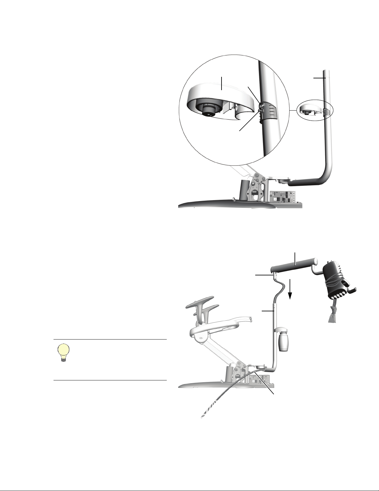
I NSTALL THE D ENTAL LIGHT
The procedure for installing A-dec 371 or
A-dec 571 for 300 dental light components is
the same regardless of the type of chair they
are installed on. Routing and connecting the
light cable varies depending on the system
you are installing.
Install the Dental Light Components
1. Slide the trim ring onto the top of the
support center post then insert the
intermediate post into the support center
post.
Orient the plugged hole in the
intermediate post toward the toeboard.
NOTE When the post is fully
seated, there is still a gap
between the white painted
sections. The gap will be behind
the support center covers.
Tools Needed For This Section
Rubber mallet Phillips head screwdriver
Figure 56. A-dec 371 Dental Light
Figure 57. Install the Dental Light
2. Lightly tap the top of the intermediate
post with a rubber mallet. Do not hit it
too hard or it will be difficult to remove.
3. Insert the plastic bearing into the
intermediate post.
4. Place the trim cover on the light post.
5. Route the light cable into the
intermediate post.
6. Insert the light post into the intermediate
post until fully seated and slip the trim
cover down over the bearing and
intermediate post.
34 86.0087.00 Rev E
Page 35

Install the Dental Light
A-dec 371 Light Cable
A-dec 571 for 300 Light Cable
Chair Circuit Board
Route and Connect the Dental Light Cables
CAUTION Electric components on the circuit board are static sensitive and require handling precautions.
1. With the dental light components installed, finish routing the light cable through the bottom of the support
center and the chair-base mount to the chair circuit board in the utilities area below the chair (see Figure 57 on
the previous page).
2. Turn off the power.
3. Attach the dental light wires for the system’s type of light to their corresponding connections on the chair
circuit board.
○ A-dec 371 has black and violet wires which connect to terminal strip J5 plus black/white and white wires
that connect to terminal strip J6.
○ A-dec 571 for 300 has black and violet wires which connect to terminal strip J5 plus black/white, white,
blue, and yellow wires that connect to terminal strip J6.
Figure 58. Dental Light Wire Connections
NOTE If you have a post mount system, see the following documents that come with the kit for installing
the A-dec 371 or A-dec 571 for 300 light on those chairs:
• A-dec 511 Dental Chair - p/n 86.0119.00
• A-dec Cascade, Decade, Performer, or Priority Dental Chairs - p/n 86.0018.00
86.0087.00 Rev E
35
Page 36

A-dec 300 System Installation Guide
Mount Arm
Clamp
Slotted Plug
Toe of the Chair
Power and
Video
Cables
Thrust Washer
I NSTALL THE M ONITOR MOUNT
The monitor mount installs on the
intermediate post.
NOTE Monitor cables are not
supplied by A-dec.
1. Use a 5/32" hex key and four 3/4" socket
head screws to attach the clamp for the
monitor toward the top of the
intermediate post. Position the mounting
hole for the monitor arm toward the toe
of the chair.
2. Use a 1/8" hex key to remove the ends
from the monitor arm.
3. Route the power and video cables
through the arm and replace the end
caps.
4. Install the thrust washer on the post on
the end of the mount arm then insert the
post into the clamp.
Tools Needed For This Section
5/32" and 1/8" hex keys
Figure 59. Monitor Mount
Figure 60. Install the Monitor Mount
5. Route the cables down through the
6. Insert the slotted plug into the square
36 86.0087.00 Rev E
TIP To make it easier for the
monitor arm to fit in the clamp
and to avoid pinching the cables,
pull the cables back into the slot
of the monitor arm.
square hole in the intermediate post and
into the support center.
hole around the wires.
Page 37

I NSTALL THE
Nothing can
extend into
this zone.
Contoured
Floor Box
Cover
Contoured Floor Box Frame
3"
76 mm
4.5"
114 mm
ONTOURED
C
F LOOR BOX
Install the Contoured Floor Box
Tools Needed For This Section
Tape measure 1/4" masonry drill bit
Phillips head screwdriver Sleeve pusher
Diagonal cutters Pliers
Install the Contoured Floor Box Frame
1. Place the contoured floor box frame
around the utilities, leaving at least
3" (76 mm) between any object that is
taller than 4.5" (114 mm) and the back of
the frame. Make sure that nothing
extends into the gray striped area in
Figure 61.
CAUTION Failure to provide
adequate space as described
above will prevent installation
of the power supply cover.
2. Attach the frame to the floor.
○ On a wood floor, use a Phillips head
screwdriver and 1-1/4" size #10
screws.
○ On a concrete floor, use a 1/4"
masonry drill bit to make holes where
the screws fit through the frame.
Insert the plastic anchors into the
holes; then use a Phillips head
screwdriver and 1-1/4" size #10
screws.
Figure 61. Contoured Floor Box Cover and Frame
86.0087.00 Rev E
37
Page 38

A-dec 300 System Installation Guide
ConvoluteCable Ties
Contoured Floor Box Frame
Power Supply Frame
Install the Convolute
1. Unplug the chair.
2. Measure the distance between the power
supply cover frame and the contoured
floor box cover frame and cut the
convolute to size.
TIP The convolute should
extend a few inches past each
frame so you can secure it to the
frames.
3. Route the convolute through the cable tie
in the power supply frame until it is
2" (5 cm) past the cable tie.
4. Use pliers to tighten the cable tie so it
securely holds the convolute. Trim the
excess tie.
5. Route the convolute through the cable tie
in the contoured floor box frame until it
is 2" (5 cm) past the cable tie.
6. Use pliers to tighten the cable tie so it
securely holds the convolute. Trim the
excess tie.
7. Route the tubing, power cord, and
vacuum line through the convolute.
Figure 62. Install the Convolute and Route the Utilities
You are ready to connect the system. See
“Connect the Utilities” on page 40 for
further instructions.
38 86.0087.00 Rev E
Page 39

I NSTALL THE
EMOTE FLOOR
R
B OX
Install the Remote Floor Box
Tools Needed For This Section
Diagonal cutters Phillips head screwdriver
5/64" hex key Sleeve pusher
1. Remove the protective layer from the
remote floor box; then position the floor
box over the utilities.
2. Measure the distance from the floor box
to the bottom of the support center and
cut the convolute to match that distance.
3. Use a Phillips head screwdriver and 6
size #10 screws to secure the floor box to
the floor.
You are ready to connect the system. See
“Connect the Utilities” on the next page for
further instructions.
Figure 63. Remote Floor Box
86.0087.00 Rev E
39
Page 40

A-dec 300 System Installation Guide
C ONNECT THE U TILITIES
See the section for the system’s
configuration.
Radius-Style Floor Box Utilities . . . . . 40
Radius-Style Modules . . . . . . . . . . . . 42
Radius-Style Assistant’s Instrumentation
(only) . . . . . . . . . . . . . . . . . . . . . . . 46
Support Center Power and Data . . . . . 47
Support Center Floor Box Utilities . . . 53
Support Center Modules . . . . . . . . . . 56
Radius-Style Floor Box Utilities
Radius-style modules connect to the utilities
in the contoured floor box. Use the umbilical
from the kit to complete the air and water
connections pictured in Figure 65.
CAUTION There is a blue tubing in
the umbilical from the kit.
Do not connect the blue tubing.
Figure 64. Radius-Style Modules with Contoured Floor Box Set
40 86.0087.00 Rev E
Page 41

Figure 65. Floor Box Tubing Connections for Radius-Style Modules
To t h e C h a i r B a s e
CAUTION Do not connect this blue tubing.
Umbilical from
the Kit
Connect the Utilities
86.0087.00 Rev E
41
Page 42

A-dec 300 System Installation Guide
Connect
Black
Wires
Connect
Gray
Wires
Plug In
Data
Lines
Connect
Ground
Wire
Mains
On/Off
Button
Blue Power Light Indicator
Cable
Ties
Radius-Style Modules
Connect the Power and Data
CAUTION Electric components on
the circuit board are static sensitive
and require handling precautions.
NOTE This procedure is for both
the assistant’s instrumentation and
the delivery system.
1. Turn off the power.
2. Use an adjustable wrench to attach the
delivery system’s ground wire to the
post on the power supply.
3. Connect the power cables to the chair
circuit board. The black wire connects to
0 VAC and the gray wire to 24 VAC.
4. Plug the data lines into any data port.
NOTE The top of the 311
power supply has a diagram of
the electrical connections for the
chair circuit board.
Figure 66. Electrical and Data Line Connections
5. Gather and cable tie the wiring.
NOTE Make sure the power
cables and data lines do not come
between the power indicator
light and the lens in the power
supply cover.
Figure 67. Properly Tied Wiring
42 86.0087.00 Rev E
Page 43

Connect the Tubing
Use the umbilical from the kit to complete
the air and water connections pictured in
Figure 68.
CAUTION There is a blue tubing in
the umbilical from the kit. Do not
connect the blue tubing.
NOTE When installing the water
manifold, be sure to connect to the
barb on the end to prevent standing
water in the manifold (see Figure 69
on page 45).
Connect the Utilities
86.0087.00 Rev E
43
Page 44

A-dec 300 System Installation Guide
To F l o o r B o x
To Assistant’s
Syringe
To F o o t C o n t r o l
Power Supply
To D e l i v e r y S y s t e m
With a Moisture Separator (Optional)
If the system includes a moisture separator, make the
connections in this gray area.
To install the moisture separator, use the directions
included in the moisture separator kit
(p/n 41.1477.00).
Umbilical from
the Kit
Pinch
Valve
CAUTION Do not
connect this blue tubing.
Figure 68. Radius-Style Modules Utility Connections
44 86.0087.00 Rev E
Page 45

Connect the Utilities
Make sure
to connect
to this barb.
Pinch Valve
Tubing Ridges Face Up
Remove This Sticker
6. If the system has an assistant’s
instrumentation, install the pinch valve
on the syringe yellow and red tubing.
7. Use a 3/16" hex key to secure the foot
control tubing to the chair base in the
strain relief.
NOTE For proper positioning, the
ridges on the foot control tubing
face up to match the grooves in the
strain relief.
Figure 69. Install the Pinch Valve
Figure 70. Secure the Foot Control Tubing
8. Carefully remove the sticker from the top
of the front mount.
Figure 71. Remove the Routing Sticker
86.0087.00 Rev E
45
Page 46

A-dec 300 System Installation Guide
Connect
Black
Wires
Connect
Gray
Wires
Plug In
Data
Lines
Syringe
Water
Syringe
Air
Pinch
Valve
Radius-Style Assistant’s Instrumentation (only)
Connect the Power and Data
CAUTION Electric components on
the circuit board are static sensitive
and require handling precautions.
1. Turn off the power.
2. Connect the power cables to the chair
circuit board. The black wire connects to
0 VAC and the gray wire to 24 VAC.
3. Plug the data lines into any data port.
Figure 72. Electrical and Data Line Connections
Connect the Tubing
1. Connect the utilities as shown in
Figure 73:
○ Use the umbilical from the kit to
complete the air connection.
○ Connect the water manifold to a
2. Install the pinch valve on the syringe
tubing.
3. For the rest of the utility connections, see
“Install the Contoured Floor Box” on
page 37 and the instructions that come
with the remote water bottle.
remote water bottle.
NOTE When installing the
water manifold, be sure to
connect to the barb on the end to
prevent standing water in the
manifold.
Figure 73. Route and Connect the Syringe Tubing
46 86.0087.00 Rev E
Page 47

Support Center Power and
Connect
Black
Wire
Connect
Gray
Wire
Plug In
Data
Line
Connect
Ground
Wire
Mains
On/Off
Button
Data
CAUTION Electric components on
the circuit board are static sensitive
and require handling precautions.
Base Mount Systems
1. Turn off the power.
2. Use an adjustable wrench to connect the
ground wire.
3. Connect the power cables to the chair
circuit board terminal strip J3. The black
wire connects to 0 VAC and the gray
wire to 24 VAC.
4. Plug the data line into any data port.
NOTE The top of the 311 power
supply has a diagram of the
electrical connections for the chair
circuit board.
Connect the Utilities
Figure 74. Electrical and Data Line Connections
86.0087.00 Rev E
47
Page 48

A-dec 300 System Installation Guide
Power
Cables
Data
Line
Ground Wire
Power Sup ply
Retaining
Clip
Inside of Floor Box
Post Mount System on an A-dec 511 Dental Chair
1. Route the power cables and data line
through the bottom of the support center,
underneath the mount, and down the lift
arm to where the power supply is
located.
2. Turn off the power.
3. Use a Phillips head screwdriver to
connect the ground wire to the screw on
top of the power supply.
4. Connect the power cables to the chair
circuit board terminal strip J2. The black
wire connects to 0 VAC and the gray
wire to 24 VAC.
5. Plug the data line into a data port on the
chair circuit board.
6. Route the support center tubing group
through the convolute.
7. Push the convolute up several inches
through the bracket in the bottom of the
support center frame until it is securely
attached.
8. Connect master toggle to power supply
air electric switch.
Figure 75. A-dec 511 Power and Data Connections
9. Route the umbilical into the floor box.
10.Use a 5/64" hex key to attach the
retaining clip to the floor box and secure
the convolute.
11.Insert the plugs into the unused holes in
the floor box.
Figure 76. Attach the Retaining Clip Inside the Remote Floor Box
48 86.0087.00 Rev E
Page 49

Connect the Utilities
Retaining Clip
Inside of Floor Box
Ground Wire
0 VAC
24 VAC
Post Mount System on an A-dec Cascade, Decade, or Performer Dental Chair
Complete the procedure for the system’s
type of chair circuit board.
Chair Circuit Board Without Data Ports
NOTE A-dec 300 touchpads cannot
operate the auto dental light and
chair movements when using this
chair circuit board.
1. Route the tubing group and wires from
the bottom of the support center through
the convolute.
2. Push the convolute up several inches
through the bracket in the bottom of the
support center frame until it is securely
attached.
Figure 77. Chair Circuit Board Without Data Ports
Figure 78. Attach the Retaining Clip Inside the Remote Floor Box
3. Route the umbilical into the floor box.
4. Use a 5/64" hex key to attach the
retaining clip to the floor box and secure
the convolute.
5. Turn off the power.
6. In the floor box, use a Phillips head
screwdriver to connect the ground wire
to the top of the power supply.
7. Connect the power cables to the power
supply. The black wire connects to
0 VAC and the gray wire to 24 VAC.
8. Insert the plugs into the unused holes in
the floor box.
Figure 79. Power Supply Connections
86.0087.00 Rev E
49
Page 50

A-dec 300 System Installation Guide
Data Ports
Chair Circuit Board With Data Ports
NOTE A-dec 300 touchpads can
operate the auto dental light and
chair positions when using this
chair circuit board.
1. Take the extra data line from the floor
box kit and plug it into a data port on the
support center port board.
2. Route the data line under the support
center mount and through the chair to
the chair circuit board.
NOTE Cable ties and
adhesive-backed mounts are
provided with the Performer
post mount chair adaptor
(p/n 77.0922.00). Use them to
secure the data line under the
chair adaptor.
3. Plug the data line into a data port on the
chair circuit board.
4. Route the tubing group and wires from
the bottom of the support center through
the convolute.
5. Push the convolute up several inches
through the bracket in the bottom of the
support center frame until it is securely
attached.
Figure 80. Chair Circuit Board With Data Ports
50 86.0087.00 Rev E
Page 51

Connect the Utilities
Retaining
Clip
Inside of Floor Box
Ground
Wire
0 VAC 24 VAC
6. Route the umbilical into the floor box.
7. Use a 5/64" hex key to attach the
retaining clip to the floor box and secure
the convolute.
Figure 81. Attach the Retaining Clip Inside the Remote Floor Box
8. Turn off the power.
9. In the floor box, use a Phillips head
screwdriver to connect the ground wire
to the top of the power supply.
10.Connect the power cables to the
power supply. The black wire connects
to 0 VAC and the gray wire to 24 VAC.
11.Insert the plugs into the unused holes in
the floor box.
Figure 82. Power Supply Connections
86.0087.00 Rev E
51
Page 52

A-dec 300 System Installation Guide
Retaining
Clip
Inside of Floor Box
Ground
Wire
0 VAC 24 VAC
Post Mount System on an A-dec Priority Dental Chair
1. Route the tubing group, power cables,
and data line from the support center
through the convolute.
2. Push the convolute up several inches
through the bracket in the bottom of the
support center frame until it is securely
attached.
3. Route the umbilical into the floor box.
4. Use a 5/64" hex key to attach the
retaining clip to the floor box and secure
the convolute.
Figure 83. Attach the Retaining Clip Inside the Remote Floor Box
5. In the floor box, plug in the data line.
6. Turn off the power.
7. Use a Phillips head screwdriver to
connect the ground wire to the top of the
power supply.
8. Connect the power cables to the power
supply. The black wire connects to 0
VAC and the gray wire to 24 VAC.
9. Insert the plugs into the unused holes in
the floor box.
Figure 84. Power Supply Connections
52 86.0087.00 Rev E
Page 53

Connect the Utilities
To the Support
Center
NOTE For moisture separator tubing connections, see Figure 86.
Support Center Floor Box Utilities
The following instructions are for both base mount and post mount systems.
Support Center tubing can connect in several locations. See the section that applies to where your system’s
utilities are located.
• Contoured Floor Box – See Figure 85 below.
• Integrated Floor Box and Remote Floor Box – See Figure 87 on page 55.
NOTE There is an overall flow diagram on the inside of the support center cover.
Contoured Floor Box
Figure 85. Support Center Utility Connections in a Contoured Floor Box
86.0087.00 Rev E
53
Page 54

A-dec 300 System Installation Guide
From the Floor Box
Power Supply
Figure 86. Moisture Separator Tubing Connections for Support Center Modules with a Contoured Floor Box Cover Set
54 86.0087.00 Rev E
Page 55

Integrated and Remote Floor Boxes
With a Moisture Separator (Optional)
If the system includes a moisture separator, make the
connections in this gray area.
To install the moisture separator, use the directions
included in the moisture separator kit
(p/n 41.1477.00).
Power Supply
To Support Center
Support center utilities in integrated and remote floor boxes connect in the same way.
Figure 87. Support Center Utility Connections in Integrated and Remote Floor Boxes
Connect the Utilities
86.0087.00 Rev E
55
Page 56

A-dec 300 System Installation Guide
Data Ports
Ground Wire
WAGO Connector
Support Center Modules
Connect the Power and Data
CAUTION Electric components on
the circuit board are static sensitive
and require handling precautions.
NOTE This procedure is for both
the assistant’s instrumentation and
the delivery system.
1. Turn off the power.
2. Use an adjustable wrench to attach the
delivery system’s ground wire to the
post below the window in the support
center frame.
3. Attach the power cables to the WAGO
connectors, keeping the gray wires with
gray wires (24 VAC) and black wires
(0 VAC) with black.
4. Plug the data line into any data port.
Figure 88. Delivery System Electrical and Data Line Connections
Connect the Tubing
1. For utility connections, see the diagram
for your system’s configuration:
○ System without a cuspidor - Figure 89
on page 57
○ System with a cuspidor - Figure 90 on
page 58
56 86.0087.00 Rev E
NOTE When making the
connections, be sure the tubing is
routed through the bottom of the
support center frame and you
make all connections inside of
the support center frame.
Page 57

Figure 89. Support Center Modules Utility Connections - No Cuspidor
To D e l i v e r y S y s t e m
To
Assistant’s
Syringe
To F o o t C o n t r o lTo F l o o r B o x
Connect the Utilities
86.0087.00 Rev E
57
Page 58

A-dec 300 System Installation Guide
To D e l i v e r y S y s t e m
To
Assistant’s
Syringe
To F o o t C o n t r o lTo F l o o r B o x
To C u s p i d o r
Figure 90. Support Center Modules Utility Connections - With Cuspidor
58 86.0087.00 Rev E
Page 59

Connect the Utilities
Pinch Valve
Tubing Ridges Face Up
2. If the system has an assistant’s
instrumentation, install the pinch valve
on the syringe yellow and red tubing.
3. Use a 3/16" hex key to secure the foot
control tubing to the chair base in the
strain relief.
NOTE For proper positioning, the
ridges on the foot control tubing
face up to match the grooves in the
strain relief.
Figure 91. Install the Pinch Valve
Figure 92. Secure the Foot Control Tubing
86.0087.00 Rev E
59
Page 60

A-dec 300 System Installation Guide
Cupfill Spout
Bowl Screen
Bowl Rinse Spout
Cuspidor Bowl
I NSTALL THE C USPIDOR
If the system has a cuspidor, install its
components.
Install the Cupfill Spout
To install the cupfill spout, push it straight
down.
CAUTION When installing the
cupfill spout, do not rotate it or it
may break.
Install the Bowl Rinse Spout
To install the bowl rinse spout, push it
straight in.
Tools Needed For This Section
Diagonal cutters
Figure 93. A-dec 361 Support Center with Cuspidor
Figure 94. Cuspidor Components
Install the Cuspidor Bowl and Bowl Strainer
1. Use diagonal cutters to cut the cable tie
and remove the positioning guide.
2. Place the cuspidor bowl in its holder
with the high side away from the patient.
3. Place the bowl screen in the bottom of
the bowl.
NOTE Save the positioning
guide and the foam plug holding
it in the cuspidor bowl support.
You will need them later to
verify proper clearance between
the cuspidor bowl and armrest.
For more information, see
“Verify Proper Clearance
Between the Cuspidor Bowl and
the Armrest” on page 94.
60 86.0087.00 Rev E
Page 61

I NSTALL
Upholstery
Pin
Install Upholstery
U PHOLSTERY
The upholstery for the A-dec 311 Dental
Chair includes the seat, back, and either a
patient-adjustable neck support or
double-articulating headrest.
Tools Needed For This Section
7/64" hex key
Figure 95. A-dec 311 Thin-Line Back with Adjustable Neck Support
Install the Seat Upholstery
1. Raise the chair and lower the chair back
until the holes in the chair frame are
accessible.
2. Move the armrests back.
3. Pull the pins out of the upholstery far
enough so the seat upholstery can sit
properly on the chair frame.
4. Place the seat upholstery in position and
line up its holes for the pins with the
holes in the chair frame.
5. Push the pins back through the seat
upholstery and chair frame until the
rings touch the seat.
86.0087.00 Rev E
Figure 96. Install the Seat Upholstery
61
Page 62

A-dec 300 System Installation Guide
Key Hole
Fastener Post
Install the Back Upholstery
NOTE Back upholstery installation
is the same for both back styles.
1. Put the chair back up and lower the
chair.
2. Place the key holes in the back
upholstery over the fastener posts on the
chair back.
3. Slide the back upholstery into place and
push down until the back upholstery
aligns with the chair back.
Figure 97. Install the Back Upholstery
Install the Neck Support or Headrest
Install a Patient-Adjustable Neck Support
Snap the neck support armature into the
neck support track.
Figure 98. Install the Patient-Adjustable Neck Support
62 86.0087.00 Rev E
Page 63

Install Upholstery
Mounting
Screws
Headrest Back
Plate
Glide Bar
Install the Double-Articulating Headrest
1. Use a 1/8" hex key to remove the
mounting screws from the headrest
upholstery.
2. Line up the holes in the headrest
upholstery with those in the headrest
back plate.
3. Insert and tighten the mounting screws.
Figure 99. Install the Double-Articulating Headrest Upholstery
4. Place the glide bar into the slot at the top
of the back upholstery and push it down
into place.
Figure 100. Install the Double-Articulating Headrest
86.0087.00 Rev E
63
Page 64

A-dec 300 System Installation Guide
Cable Tie
Around
Support
Center
Post
Cable Tie Around Tubing
Bundle Inside Mount
Cable Tie
Around Corner
of the Mount
Lubricate
O-Ring
P REPARE AND
DJUST THE
A
S YSTEM
Secure the Base Mount System Tubing Bundle
1. Loosely loop a cable tie around the
tubing bundle and slide the tie under the
chair-base mount.
2. From the utilities area, pull the tubing
bundle to take up any slack.
3. Tighten the cable tie under the mount
and push the tubing bundle up into the
mount so it is not visible.
4. Use a cable tie around the corner of the
mount to secure the wires and tubing so
nothing is hanging down under the
mount.
5. Use a cable tie to secure the tubing group
to the support center post so it does not
push against the lower covers.
Tools Needed For This Section
1/2" combination wrench Voltmeter
Hex key set Phillips head screwdriver
Figure 101. Secure the Tubing Bundle
Figure 102. Install the Water Bottle
Install the Water Bottle
The instructions for installing a water bottle
are the same regardless of where it is
located.
1. Following ICX instructions, place an ICX
tablet (p/n 90.1065.00) in the water
bottle.
2. Fill the bottle with water.
3. Put A-dec silicone lubricant on the
receptacle O-ring.
CAUTION Use only A-dec
silicone lubricant or the O-ring
may be damaged.
4. Push the water bottle up onto the water
bottle receptacle and turn it to the right.
64 86.0087.00 Rev E
Page 65

Prepare and Adjust the System
Stop Screw
(From Front)
Stop Screw
(From Back)
Te ns io n
Adjustment
Screw
Tension
Adjustment
Screw
Adjustments
Lock the Armrests (Optional)
When the dental chair is shipped, the
armrests rotate back and forth. The armrests
can be locked into the upright position if
preferred. To lock an armrest:
1. Use a 3/16" hex key to remove the stop
screw from the front of the armrest.
2. Install the stop screw in the back of the
armrest.
3. Use a 1/8" hex key to tighten the tension
adjustment screw on the front of the
armrest.
Figure 103. Adjust the Armrest Position
Adjust the Double-Articulating Headrest Glide Bar Tension
A double-articulating headrest may be
difficult to move or may drift downward
because of the amount of tension on the
glide bar.
To adjust the tension, use a 1/8'' hex key and
turn the tension adjustment screw clockwise
to increase friction or counterclockwise to
decrease friction.
Figure 104. Adjust the Double-Articulating Headrest Glide Bar
Ten si on
86.0087.00 Rev E
65
Page 66

A-dec 300 System Installation Guide
Base Down
Control Valve
Adjustment
Screw
Adjust the Speed for Lowering the Chair
To adjust the speed at which the chair
lowers, raise the chair and use a 3/32" hex
key to adjust the base down control valve.
Turn the screw clockwise to decrease speed
or counterclockwise to increase speed.
TIP For an accurate estimate of
down travel speed, have someone
sit in the chair when making the
adjustments.
Figure 105. Adjust the Base Down Control Valve
66 86.0087.00 Rev E
Page 67

Prepare and Adjust the System
End Cap
Button
Head
Screw
Flexarm Spring Adjustment Screw
Adjust the Delivery System Spring-Assisted Flexarm
If the control head drifts up or down,
complete the following steps to adjust the
spring-assisted flexarm.
NOTE After adjusting the flexarm,
test for balance at its normal
working position.
1. Turn off the power.
2. Load the control head for normal use,
attaching handpieces and placing a tray
with instruments on the tray holder.
3. Use a 1/8" hex key to loosen the screw
that secures the end cap.
TIP Lower the control head
for easier access to the
button head screw.
4. Remove the flexarm end cap.
5. Use a 3/16" hex key to adjust the flexarm
spring adjustment screw until the control
head maintains position at the normal
working position.
TIP To make it easier to adjust
the spring, raise the control head
to the highest point.
○ If the control head drifts up, turn the
screw counterclockwise.
○ If the control head drifts down, turn
the screw clockwise.
Figure 106. Adjust the Spring-Assisted Flexarm
86.0087.00 Rev E
67
Page 68

A-dec 300 System Installation Guide
Install the
10-32 x 1/2"
button head
stop screw
(actual size)
in the
bottom hole.
Adjust the Delivery System Flexarm Rotation Tension
Do not adjust the flexarm rotation tension
until the system has been leveled. For
information on adjusting the flexarm
rotation, see “Adjust the Delivery System
Flexarm Rotation Tension” on page 79.
Install the Delivery System Flexarm Rotation Stop Screw
Use a 1/8" hex key to install the 10-32 x 1/2"
button head screw in the bottom hole on the
knuckle of the delivery system. Tighten it all
the way down.
Adjust the Control Head Rotation Tension
Figure 107. Install the Flexarm Rotation Stop Screw
Figure 108. Adjust the Control Head Rotation Tension
If the control head rotation is too tight or too
loose, adjust the rotation tension by
tightening or loosening the screw under the
control head.
Use a 5/32" hex key to turn the screw
clockwise to increase tension and
counterclockwise to decrease tension.
68 86.0087.00 Rev E
Page 69

Prepare and Adjust the System
Hex Key
Control
Head
Tr ay
Holder
Tr ay
Arm
Mounting
Bracket
A
B
C
D
E
Adjust the Tray Rotation Tension
If the tray holder rotation is too tight or too
loose, adjust the tray rotation tension.
1. Insert a 1/8" hex key through the
mounting bracket. If necessary, rotate
the holder or arm until the key slides
completely into the mounting bracket.
2. While holding the hex key in the
bracket, rotate the tray clockwise to
increase the tension and
counterclockwise to decrease tension.
For Continental-style delivery, you may
need to make this adjustment in two
locations: under the control head and under
the tray holder.
Figure 109. Adjust the Tray Holder on a Traditional Control Head
Figure 110. Adjust the Tray Holder on a Continental Control Head
86.0087.00 Rev E
69
Page 70

A-dec 300 System Installation Guide
Air Coolant
Flow Control
Water Coolant
Flow Control
Adjust Handpieces
A-dec 300 delivery systems supply and
regulate air and water to operate dental
handpieces, syringes, and ancillary devices.
To adjust handpieces, complete the
following sections in their order for each
handpiece.
1) Water Coolant Flow
The A-dec 300 system includes a water
coolant flow control for each handpiece.
1. Turn the drive air, air coolant, and water
coolant all the way down.
CAUTION Air and water coolant
adjustment keys are not
intended to completely
shut off flow.
For instructions on accessing drive air
pressure controls, see “3) Drive Air
Pressure”on the next page.
2. Lift a handpiece from the holder.
Figure 111. Handpiece Adjustment Keys
3. Flip the wet/dry toggle toward the blue dot on the foot control.
4. Press the foot control to activate the handpiece.
5. Use the adjustment keys on the side of the control head to adjust the water coolant flow (normally about 1
drop every 2 seconds):
○ Turn the control clockwise to decrease flow.
○ Turn the control counterclockwise to increase flow.
2) Air Coolant Flow
The air coolant flow control adjusts the air coolant flow to all handpieces.
1. With the handpiece out of its holder, press the foot control to activate the handpiece.
2. Adjust the air coolant flow until the spray is a fine mist.
○ Turn the control clockwise to decrease flow.
○ Turn the control counterclockwise to increase flow.
CAUTION Do not continue turning the air coolant adjustment key left when the flow is no longer
increasing. The stem may come out completely.
70 86.0087.00 Rev E
Page 71

Prepare and Adjust the System
Control Head Back
Cover Screws
Drive Air Pressure Control
3) Drive Air Pressure
The optional deluxe touchpad allows you to
easily check drive air pressure. On the
touchpad, press and hold the Plus (+) and
Minus (–) buttons at the same time. If an
adjustment is necessary, use a 7/64" hex key
to remove the control head back cover and
complete the steps below for each
handpiece.
NOTE Use a handpiece pressure
gauge attached to the handpiece
tubing for exact drive air
measurement or if you do not have
a deluxe touchpad. One bar equals
14.5 psi.
1. Lift the handpiece from the holder.
2. Locate the drive air pressure controls
inside the control head.
3. Set the wet/dry toggle to dry.
4. Press the foot control.
5. With the handpiece running, watch the
deluxe touchpad readout or handpiece
pressure gauge and adjust the handpiece
drive air pressure to meet manufacturer’s
specifications.
• Turn the control clockwise to
decrease flow.
• Turn the control counterclockwise
to increase flow.
Figure 112. Remove the Control Head Back Cover
Figure 113. Adjust the Drive Air Pressure
Complete these steps for each handpiece.
NOTE Adjust the drive air pressure
to meet the handpiece
manufacturer’s drive air pressure
specification. See the handpiece
documentation for the drive air
pressure specification.
86.0087.00 Rev E
71
Page 72

A-dec 300 System Installation Guide
Use Buttons to
Adjust Voltage
IOLS Output Terminals
Adjust the Intraoral Light Source Voltage
To adjust the intraoral light source, complete
the following steps.
1. Use a 7/64" hex key to remove the
control head back cover (see Figure 112
on page 71).
2. Set the voltmeter to DC voltage and place
its probes on the IOLS output terminals
for the handpiece you're adjusting.
3. Lift the handpiece from its holder and
turn the light on.
4. Use the buttons behind the terminal to
adjust the voltage according to the
following table.
Figure 114. Adjust the Intraoral Light Source Voltage
NOTE The following table pertains to fiber optics with 26 AWG wires, 750mA loads, and a desired bulb
voltage of 3.2 VDC. For fiber optics powered with 26AWG wires and other ratings, use the
equation T = (Z x 0.006 x Y) + X where:
T = Terminal strip voltage (VDC)
X = Desired voltage at lamp (VDC)
Y = Rated lamp/load current (in Amps)
Z = Length of 26AWG wire (inches) from terminal strip to lamp
Length and Voltage Table
Voltage at terminal strip
Wire length in
A-dec tubing
(in) (cm) VDC +/- .02 (in) (cm) VDC +/- .02
48 122 3.40 108 274 3.69
54 137 3.43 114 290 3.72
60 152 3.46 120 305 3.75
66 168 3.49 126 320 3.78
72 183 3.52 132 335 3.81
78 198 3.55 138 351 3.84
84 213 3.58 144 366 3.87
90 229 3.61 150 381 3.90
96 244 3.64 156 396 3.93
102 259 3.67
A-dec/W&H, Bien Air or
other bulbs rated at 3.2V
Wire length in
A-dec tubing
Voltage at terminal strip
A-dec/W&H, Bien Air or
other bulbs rated at 3.2V
72 86.0087.00 Rev E
Page 73

Prepare and Adjust the System
Adjust
Air Flow
Adjust Water Flow
Doctor’s Syringe
Least
Te ns io n
Most
Te ns i on
Bail
Spring
Whip
Drip Shield
Adjust Syringes
To adjust the water and air flow for
syringes, complete the following steps.
1. Access the pinch valve:
○ For the doctor’s syringe, use a 7/64"
hex key to remove the control head
back cover (see Figure 112 on
page 71).
○ For the assistant’s syringe, go to the
support center.
2. On the syringe, push the water button.
3. Tighten or loosen the screw on the pinch
valve to adjust the water flow.
4. Push both buttons on the syringe.
5. Tighten or loosen the screw on the pinch
valve to adjust the air flow until there is a
fine mist.
Figure 115. Adjust the Syringe Flow
Adjust the Continental Whip Ten si on
1. Use a 7/64" hex key to remove the
control head back cover (see Figure 112
on page 71).
2. Use a 7/64" hex key to undo the two
screws holding the control head front
cover and raise the cover up.
3. Pull the two tabs on the top of the drip
shield out; then pull down the shield.
4. Remove the spring from the front cover
and the bail.
5. Pull the whip forward.
6. To remove the bail from the control head,
squeeze its sides until its ends clear the
holes in the frame holding the bail.
7. Insert the ends of the bail into the holes
for the desired whip tension; then replace
the spring. The deepest hole provides the
least tension.
8. Repeat steps 4 through 7 for each whip to
be adjusted.
9. Replace the drip shield and control head
covers.
Figure 116. Adjust the Continental Whip Tension
86.0087.00 Rev E
73
Page 74

A-dec 300 System Installation Guide
End Cap
Cover
Screw
Cover
Adjust the Dental Light Flexarm Counterbalance
If the dental light drifts up or down,
complete the following steps to adjust the
flexarm counterbalance.
1. Use a Phillips head screwdriver to
remove the end cap.
2. Use a 5/16" hex key to remove the two
screws that secure the cover.
3. Remove the cover.
4. Use a 1/2" combination wrench to adjust
the nut on the end of the spring.
If the dental light drifts up, turn the nut
counterclockwise. If the dental light
drifts down, turn the nut clockwise.
5. Set the cover back onto the flexarm (but
do not reattach it yet), and check for drift.
6. Repeat steps 3 and 4 until drift is
eliminated.
Figure 117. Adjust the Dental Light Flexarm Counterbalance
NOTE An optional travel stop limit
kit (p/n 90.1044.00) can be installed
to limit the upward and downward
motion of the flexarm.
74 86.0087.00 Rev E
Page 75

Prepare and Adjust the System
Horizontal Rotation
Tension Screws
Vertical Tension Screw
Adjust the A-dec 371 Dental Light Swivel Tension and Vertical Drift
If the light head is difficult to position,
moves too easily, or tends to drift out of
position, complete the following steps to
adjust the horizontal and vertical tension.
• For horizontal rotation, use a 5/32" hex
key to adjust the screw at the top of the
switch housing.
Turn the screw clockwise to increase
tension and counterclockwise to
decrease tension.
Figure 118. Horizontal Rotation Adjustments
Figure 119. Vertical Rotation Adjustments
• For vertical rotation, use a 3/16" hex key
to adjust the tension.
Turn the screw clockwise to increase
tension and counterclockwise to
decrease tension.
86.0087.00 Rev E
75
Page 76

A-dec 300 System Installation Guide
Bowl Rinse
Flow Pinch
Valve
Support
Center
Cover
Monitor Handle
Horizontal
Te n s io n S c r e w
Adjust the Cuspidor Bowl Rinse Flow Settings
Complete the following steps to adjust the
bowl rinse flow, located inside the support
center.
1. Remove the upper support center cover
by pulling out on the lower edges of the
cover.
2. With the cuspidor bowl rinse on, tighten
or loosen the pinch valve to adjust the
flow.
3. Rotate the bowl rinse spout to adjust the
flow pattern and achieve the best rinsing
action.
4. Use the touchpad buttons to set the
length of cupfill and bowl rinse flow (see
“Cupfill and Bowl Rinse” on page 81 for
more information).
Figure 120. Bowl Rinse Flow Pinch Valve Location
Adjust the Monitor Tilt and Drift
If you want to change the tilt of the monitor
or if it tends to drift out of position,
complete the following steps to make
adjustments.
• To adjust the tilt of the monitor, turn the
monitor handle to the left, adjust the
angle of the monitor; then turn the
handle to the right to lock it in position.
• To adjust the horizontal drift of the
monitor, use a 5/16" hex key to tighten or
loosen the horizontal tension screw.
Figure 121. Adjust the Monitor Mount Tilt and Drift
76 86.0087.00 Rev E
Page 77

L EVEL THE SYSTEM
Magnetic
Level
One Set of
Leveling
Screws
Complete the following sections to level the
system. A level system prevents the
modules from drifting and instruments from
rolling around the tray.
NOTE To successfully level the
system, it is important to complete
the following sections in the order
that they are listed.
1. Level the Support Center
1. Move the control head and dental light
into the normal working position for the
doctor.
2. Place a magnetic level vertically on the
knuckle of the delivery system’s rigid
arm. Align the level with a set of leveling
screws that are on opposite sides of the
chair-base mount.
Level the System
Tools Needed For This Section
Magnetic level Hex key set
Figure 122. Level the Support Center
TIP If needed, use a piece of tape
to help hold the level in place.
3. Use a 3/16" hex key to adjust the 4
leveling screws while moving the level’s
alignment from one set of screws to the
other.
4. Once the system is level, securely tighten
the leveling screws.
86.0087.00 Rev E
77
Page 78

A-dec 300 System Installation Guide
Button Head
Screw
Adjust to Level
Front to Back
Adjust to Level
Side to Side
Control Head
Flex Arm
2. Level the Delivery System
1. With the control head in the normal
working position for the doctor, turn it so
it faces straight out from the flex arm.
2. Place a level on the tray holder, if the
system has one, or on top of the control
head.
3. Use a 5/32" hex key to loosen the
button-head screw holding the control
head in place.
4. Make the following adjustments to level
the control head. When making
adjustments, align the level with the
screws you are adjusting (see Figure 123).
○ Use a 5/32" hex key to level the
control head from side to side.
○ Use a 5/32" hex key to level the
control head from front to back.
5. Tighten the button-head screw to hold
the control head in place.
Figure 124. Delivery System Ready to be Leveled
Figure 123. Level the Delivery System
NOTE If the system does not have an assistant’s instrumentation mounted on a telescoping arm, you
have completed the leveling process and can skip to “Adjust the Delivery System Flexarm Rotation
Tension” on page 79.
78 86.0087.00 Rev E
Page 79

Level the System
Level
Extended Telescoping Arm
Rotation Tension
Setscrew is on Top
3. Level the Assistant’s Instrumentation Telescoping Arm
1. Extend the telescoping arm and align it
parallel to the chair.
2. Place a level on top of the telescoping
arm.
3. Use a 1/8" hex key to level the arm.
Figure 125. Level the Assistant’s Instrumentation Telescoping Arm
Adjust the Delivery System Flexarm Rotation Tension
NOTE This adjustment must be
made after the final leveling of the
system. For information on other
adjustments, see “Prepare and
Adjust the System” on page 64.
If the delivery system arm drifts, complete
the following steps to adjust the tension of
the flexarm rotation.
1. Load the control head for normal use.
2. Use a 1/8" hex key to turn the setscrew
clockwise to increase tension and
counterclockwise to decrease tension.
Figure 126. Adjust the Delivery System Flexarm Rotation Tension
86.0087.00 Rev E
79
Page 80

A-dec 300 System Installation Guide
T OUCHPAD S ETTINGS
Dental Chair and Light Settings
Use the touchpad to program commonly
used settings for the system. The touchpad
comes with the following preset positions:
•Entry/Exit
•Treatment 1
• Treatment 2 (Standard touchpad only)
•X-ray/Rinse
Program the Chair Positions
To program Entry/Exit, Treatment 1, and
Treatment 2 buttons:
Figure 127. Standard and Deluxe Touchpads
NOTE Touchpad symbols are proprietary to A-dec Inc.
Table 1. Chair Preset Positions
Button Position Description
Entry/Exit: Automatically positions chair for
entry/exit and turns off the dental light.
1. Move the chair into the desired position.
2. Press and release and you hear a
beep indicating program mode.
3. Press the button you want to program
and you hear three beeps confirming the
button has been set.
Customize the X-Ray/Rinse Button
The X-ray/Rinse button functions as either
x-ray/rinse or as another fully
programmable preset position
(Treatment 3). To change the function:
1. Press and hold buttons and at the
same time for three seconds.
○ One beep indicates the button has
been configured as Treatment 3.
○ Three beeps indicate that the
X-ray/Rinse button has been
configured as the x-ray/rinse function
(alternates between the x-ray/rinse
and the previous position).
Treatment 1: Automatically positions the chair
base and back down and turns on the dental light.
Treatment 2 (Standard touchpad only):
Automatically positions the chair base and back
and turns on the dental light.
X-ray/Rinse: Automatically positions the chair for
either x-ray or rinse. Toggles between the xray/rinse and the last position, and turns off the
dental light.
NOTE The A-dec 300 has a fixed cuspidor, which
requires setting both the base and back position.
80 86.0087.00 Rev E
Page 81

2. Program the preset position as instructed
in the previous section, “Program the
Chair Positions” on page 80.
TIP If X-ray/Rinse is changed to a
fully programmable preset position,
it operates the same as Treatment
buttons 1 and 2.
Cupfill and Bowl Rinse
The cupfill controls water flow from the
water bottle into a cup. The bowl rinse
provides rinse water for the cuspidor. See
Table 2 for those buttons preset run times.
To change the timing for the cupfill and
bowl rinse:
1. Press and release . One beep indicates
the programming mode is ready.
NOTE You can also enter the
cuspidor programming mode by
pressing and holding both the
Cupfill and Bowl Rinse buttons
located near the spout. One beep
indicates the programming mode is
ready.
To u c h p a d S e t t in g s
Table 2. Cupfill and Bowl Rinse Presets
Button Position Description
Cupfill Button: Controls water flow from the
water bottle into a cup.
• Press the Cupfill button for a timed operation.
The factory preset is a 2.5 second fill.
• Press and hold the Cupfill button for manual
operation.
Bowl Rinse Button: Provides rinse water for the
cuspidor bowl.
• Press the Bowl Rinse button for a timed
operation. The factory preset is a 30 second
rinse.
• Press and hold the Bowl Rinse button for
manual operation.
2. Press and hold the Cupfill or Bowl
Rinse button for the desired amount
of time.
3. Release the button. Three beeps confirm
the setting.
TIP If you press the Bowl Rinse
button twice in less than two
seconds, the operation changes to
continuous rinse mode. Press the
button once to end the continuous
bowl rinse mode.
86.0087.00 Rev E
81
Page 82

A-dec 300 System Installation Guide
Dental Light
Use the Dental Light button on the touchpad
to turn the dental light on or off.
Press the Dental Light button to toggle
between intensity and composite settings.
• 371 Dental Light: Toggle between high
intensity and composite.
• 571 for 300 Dental Light: Toggle
between either high or medium intensity
and composite, depending on the
selection of the intensity setting on the
light.
To turn off the dental light, hold down
for two seconds.
Auto Light Feature
When you use a programmed chair position,
the dental light turns on when the chair back
reaches operating position. Press or
and the dental light automatically turns off.
Table 3. Dental Light Button
Button Description
Dental LIght Button: Press to toggle between
intensity settings. Press the button to turn on the
light and hold the button to turn off the light.
To deactivate the auto light feature, press
and hold and at the same time for
three seconds. One beep confirms the auto
light feature is off.
To re-activate the auto light feature, press
and hold and at the same time for
three seconds. Three beeps confirm the
dental light auto feature is on.
TIP If X-ray/Rinse is changed to a
preset position, the dental light auto
feature operates the same as the
Treatment buttons 1 and 2.
82 86.0087.00 Rev E
Page 83

To u c h p a d S e t t in g s
A
B
E
C
D
Electric Handpiece Operation
You can program handpieces in standard or
endodontics mode.
• Standard mode: Handpieces are always
100 percent torqued for electric
handpieces.
• Endodontics mode: If you have a motor
controller that supports endodontics, you
can program handpieces in this mode.
Endodontics mode allows you to control
torque and ratio settings.
Program the Electric Handpieces in Standard Mode
You can program memory settings on the
deluxe touchpad for specific RPMs. To
program the handpiece setting:
1. Lift the handpiece from the holder.
2. To adjust the RPM, press the Minus (-) or
Plus (+) buttons. You see the RPM values
on the screen (see Figure 128).
3. To place the setting into memory, press
. One beep sounds.
Table 4. Electric Motor Presets (Standard Mode)
Memory Settings Preset Speed
M1 2,000 RPM
M2 10,000 RPM
M3 20,000 RPM
M4 36,000 RPM
Figure 128. Standard Mode Touchpad Screen
4. To toggle through memory settings (M1
through M4), press .
5. When the desired memory location is
selected, press . Three beeps confirm
the setting.
Forward/Reverse Button
Item Description
A Forward/Reverse Indicator (forward is shown)
B Forward/Reverse Button
C Minus and Plus Buttons
D Memory Button
ERPM Value
Use the Forward/Reverse button to change
the electric motor’s direction. The system
defaults to the forward position when you
return the motor to the holder or turn off the
power (see Figure 128). In reverse mode, the
screen icon flashes continuously.
86.0087.00 Rev E
83
Page 84

A-dec 300 System Installation Guide
L
K
J
H
A
B
C
D
E
F
G
Program Electric Handpieces in Endodontics Mode
The endodontics mode allows you to change
settings based on the specific file and
desired handpiece behavior.
NOTE For more information
regarding speed and torque limits
for a specific file, consult the file
manufacturer.
To program the endodontics memory
settings:
1. Lift the handpiece from the holder.
2. If the touchpad screen does not display
endodontics mode, press .
3. To change settings in endodontics mode,
press the Minus (-) or Plus (+) buttons.
You see a white reverse video box on the
touchpad screen.
4. To move from setting to setting on the
touchpad screen, press the chair
positioning buttons.
5. To change the setting, press the Minus (-)
or Plus (+) buttons.
6. To set the speed limit, torque limit, and
ratio into memory (optional), press
(one beep sounds); then press to
toggle through the memory locations
(M1 through M4).
7. Once the memory location is selected,
press . Three beeps confirm the
setting.
Figure 129. Endodontics Mode Touchpad Screen
Item Description Item Description
A Endodontics Mode
Button
B Forward/Reverse
Indicator (with automode indicator inside
arrow)
CFile Torque Unit
Indicator
D Forward/Reverse
Button
E "Plus" Button L Memory Setting Indicator
F Program Button
G "Minus" Button
H Memory Button
J Handpiece Ratio Setting
KSpeed Limit Indicator
84 86.0087.00 Rev E
Page 85

To u c h p a d S e t t in g s
Auto off
Auto reverse
Auto forward
Table 5 lists and defines the touchpad screen
icons for endodontics mode.
CAUTION The A-dec|W&H
endodontics attachments have
special features due to their
ball-bearing design. Their life-long
efficiency factors are stable and
known; therefore, the A-dec
endodontics system is able to
control and display file torque very
accurately. All other attachments
have unknown life-long efficiency
factors and therefore stated torque
values are approximate.
Table 5. Endodontics Mode Settings
Icon Setting Description
Speed Setpoint for file speed limit. For more
information, consult the file manufacturer.
To rq u e Setpoint for file torque limit. For more
information, consult the file manufacturer.
To rq u e
Units
Ratio Sets the handpiece ratio. For more
Forward/
Reverse
Mode
Toggles between Ncm (Newton
centimeters) and gcm (Gram centimeters).
Adjusting this setting for one handpiece
changes it for all handpiece settings.
Note: 1Ncm=102gcm.
information, consult the handpiece
manufacturer.
Adjusting this setting for one handpiece
changes it for all handpiece settings. This
icon is displayed within the
Forward/Reverse indicator.
Auto-off — The motor shuts off when the
file speed reaches the torque limit.
Auto-reverse — The motor stops and
reverses direction when the file reaches
the torque limit.
Auto-forward — When the file reaches the
torque limit, the motor stops, reverses
three turns, then changes back to forward
again.
Note: If the file is stuck, this cycle repeats
three times before the motor stops.
86.0087.00 Rev E
85
Page 86

A-dec 300 System Installation Guide
HANDPIECE SETUP
Press -/+ to change
<Back Select >
Holder Setup
Technician Touchpad Setup Options
The deluxe touchpad allows service
technician access to adjust handpiece and
touchpad settings for user preferences.
Navigate with Touchpad Buttons
Chair button functions become navigation
buttons while you are in setup mode. You
will use the back up (
button to navigate the setup screens.
Holder Setup
You can set up how handpieces are
configured for each handpiece holder.
To set up handpiece holders:
) and back down ()
1. From the deluxe touchpad main screen,
press and hold and at the same
time for three seconds; then press
begin.
2. From the System Setup screen,
press Minus (-) or Plus (+) to highlight
Handpieces (see Figure 130), and
press
.
3. From the Handpiece Setup screen,
select Holder Setup (see Figure 131), and
press
.
4. Lift the desired handpiece from the
holder.
to
Figure 130. System Setup: Handpieces
SYSTEM SETUP
Handpieces
Press -/+ to change
< Exit Select >
Figure 131. Handpiece Setup: Holder Setup Selection
86 86.0087.00 Rev E
Page 87

To u c h p a d S e t t in g s
HANDPIECE SETUP
Press -/+ to change
Select >
Electric
5. From the Handpiece Setup screen, press
Minus (-) or Plus (+) to highlight the
handpiece type (see Figure 132).
Handpiece types include Electric,
Ultrasonic, Vacuum, Other, and Turbine.
6. Press
.
Three beeps confirm the setup for the
handpiece is complete.
7. Return the handpiece to the holder.
8. Repeat steps 5 through 7 to set up each
handpiece.
9. When you are finished setting up
handpieces, press
until you see the
A-dec logo.
Light Source Setup
You can set up various intraoral light source
options if a quad voltage intraoral light
source (QVIOLS) is installed. The following
options are available:
Figure 132. Handpiece Setup: Option Selection
• On When Selected: Specify whether the
intraoral light source turns on or remains
off when the handpiece is removed from
the holder.
• Auto Off Delay: Determine how long the
light remains on when the foot control is
released. This time is reset when you use
the drive air again.
• On in Endo: Specify whether the
intraoral light source turns on or off
when in endodontics mode. Because
most enododontics handpieces do not
have light pipes, it is recommended that
Off is selected to reduce heat and to
extend bulb life.
86.0087.00 Rev E
87
Page 88

A-dec 300 System Installation Guide
LT SOURCE SETUP
On When Sel
Press -/+ to change
<Back
Select>
To set up the light source:
1. From the deluxe touchpad main screen,
press and hold and at the same
time for three seconds; then press
to
begin.
2. From the System Setup screen,
press Minus (-) or Plus (+) to highlight
Handpieces (see Figure 133), and
press
.
Figure 133. System Setup: Handpieces
SYSTEM SETUP
Handpieces
Press -/+ to change
< Exit Select >
3. From the Handpiece Setup screen,
press Minus (-) or Plus (+) to highlight
Intraoral Lt Sc (see Figure 134), and
press
.
4. Lift the desired handpiece from the
holder.
5. From the Light Source Setup screen,
press Minus (-) or Plus (+) to display the
desired option, such as On When Sel
(see Figure 135), and press
.
6. Specify options for the handpiece setting
by pressing Minus (-), Plus(+), and
to
move through the screens.
Once the setup is complete, three beeps
confirm the setting.
7. Return the handpiece to the holder.
8. Repeat steps 3 through 7 to configure
each handpiece.
9. When you are finished setting up the
handpieces, press
until you see the
A-dec logo.
Figure 134. Handpiece Setup: Intraoral Lt Sc Selection
HANDPIECE SETUP
Intraoral Lt Sc
Press -/+ to change
< Back Select >
Figure 135. Light Source Setup: Option Selection
LIGHT SOURCE SETUP
On When Sel
Press -/+ to change
< Back Select >
88 86.0087.00 Rev E
Page 89

Ultrasonic Setup
SYSTEM SETUP
Press -/+ to change
< Exit Select >
Handpieces
HANDPIECE SETUP
Press -/+ to change
Setup
Select>
<Back
HANDPIECE SETUP
Press -/+ to change
< Back Select >
Ultrasonic Setup
Specify whether to turn on or off the
ultrasonic colors.
To set up the ultrasonic:
1. From the deluxe touchpad main screen,
press and hold and at the same
time for three seconds, and press
begin.
2. From the System Setup screen,
press Minus (-) or Plus (+) to highlight
Handpieces (see Figure 136), and
press
.
to
To u c h p a d S e t t in g s
Figure 136. System Setup: Handpieces
3. From the Handpiece Setup screen,
press Minus (-) or Plus (+) to highlight
Ultrasonic Setup (see Figure 137), and
select
.
4. Press Minus (-) or Plus (+) to display On
or Off, and press
.
Three beeps confirm the setting.
5. Press
until you see the A-dec logo.
Figure 137. Handpiece Setup: Ultrasonic Setup Selection
86.0087.00 Rev E
89
Page 90

A-dec 300 System Installation Guide
Set Up Electric Options
You can change display information and the
electric functions. The following options are
available:
• Torque Units: Select how to display
the units, either Ncm (Newtons per
centimeters) or gcm (grams per
centimeters).
• Endo Handpiece Auto Mode: Configure
how the electric motor reacts when the
torque limit is reached.
○ Auto Forward: Motor will stop,
reverse three turns, and return
forward again.
○ Auto Reverse: Motor will reverse.
○ Auto Stop: Motor will stop.
• Auto Reverse Beep: Select whether to
hear three beeps from the touchpad
when auto-reversing begins.
• Torque Warning: Select whether to turn
on the beep sounds from the touchpad
when there is a torque warning.
90 86.0087.00 Rev E
Page 91

To set up electric options:
SYSTEM SETUP
Press -/+ to change
< Exit Select >
Handpieces
HANDPIECE SETUP
Press -/+ to change
< Back Select >
Electric Setup
ELECTRIC HPC SETUP
Press -/+ to change
< Back Select >
Torque Units
1. From the deluxe touchpad main screen,
press and hold and at the same
time for three seconds; press
to begin.
2. From the System Setup screen, press
Minus (-) or Plus (+) to highlight
Handpieces (see Figure 138), and
press
.
To u c h p a d S e t t in g s
Figure 138. System Setup: Handpieces
3. From the Handpiece Setup screen, press
Minus (-) or Plus (+) to highlight Electric
Setup (see Figure 139), and press
.
4. From the Electric HPC Setup screen,
press Minus (-) or Plus (+) to highlight an
option, such as Torque Units (see
Figure 140), and press
.
5. Specify options for the setting by
pressing Minus (-), Plus(+), and
to
move through the screens.
Once the setup is complete, three beeps
confirm the setting.
6. Repeat steps 4 through 5 to configure
electric settings for each handpiece.
7. When all settings are complete, press
until you see the A-dec logo.
Figure 139. Handpiece Setup: Electric Setup Selection
Figure 140. Electric Handpiece Setup: Option Selection
86.0087.00 Rev E
91
Page 92

A-dec 300 System Installation Guide
Touchpad Setup
Use the touchpad setup to change the
contrast of the touchpad display and specify
whether to display help messages in the
technical mode help screens.
To set up touchpad options:
1. From the deluxe touchpad main screen,
press and hold and at the same
time for three seconds, and press
begin.
2. From the System Setup screen, press
Minus (-) or Plus (+) to highlight
Touchpad (see Figure 141), and press
to begin.
to
Figure 141. Touchpad Setup
SYSTEM SETUP
Touchpad
Press -/+ to change
< Exit Select >
3. From the Touchpad Setup screen, press
Minus (-) or Plus (+) to highlight
Contrast or Help Messages:
○ Select Contrast to adjust the contrast
on the screen. Press Minus (-) or Plus
(+) to adjust the contrast (see
Figure 142).
○ Select Help Messages and press
Minus (-) or Plus (+) to turn on or off
the technician help messages (see
Figure 143).
4. Press
. Three beeps confirm the setting.
5. When settings are complete, press until
you see the A-dec logo.
NOTE For a listing of touchpad
help messages, see A-dec 300 Systems
Instructions For Use.
Figure 142. Touchpad Setting: Contrast
CONTRAST ADJUST
26
of 63
Press -/+ to change
< Back Save >
Figure 143. Touchpad Setting: Help Messages
HELP MESSAGES
On
Press -/+ to change
< Back Save >
92 86.0087.00 Rev E
Page 93

Test the System
T EST THE SYSTEM
After you have completed the installation of
the A-dec 300 system, use the following
checklist to test the system; then follow up
with the customer.
Dental Chair
• Dental chair is securely anchored to the
floor.
• The chair functions properly, including
the chair's lift, tilt, and programmable
functions controlled by the touchpads
and foot switch.
• Headrest or neck support is functioning
properly.
• Armrests are fixed or positionable based
on staff preference.
Delivery System
• The handpieces function properly and
are set to doctor’s preferences:
○ Water coolant, air coolant, and spray.
○ Handpiece tubing flush.
○ Handpiece holder valves and
switches.
○ Handpiece drive air pressure.
• Spring-assisted flexarm functions
properly.
• Delivery system flexarm brake functions
properly.
• Control Head is level as measured on
tray.
• Articulating arms do not drift.
• Foot control operates properly.
Assistant's Instrumentation, Cuspidor, and Cupfill
• Vacuum/suction is set to the following specifications:
○ Wet vacuum - 10±2 inches of Hg (34±7 KPa),
9 scfm (255 sl/min) minimum.
○ Dry/semi-dry vacuum - 4.5±1 inches of Hg (16±3.5 KPa),
12 scfm (340 sl/min) minimum.
• Air and water syringe buttons operate smoothly.
• Valves on HVE and saliva ejector move freely.
• Cupfill timing is set properly.
• Cuspidor flow pattern effectively rinses the bowl, and the
bowl drains properly.
• The end of the cuspidor ventilation tube is 1/2" (13mm)
above the support center frame.
• There is 1-1/8" (29 mm) clearance between the cuspidor bowl
and armrest.
Utilities
• Regulated air pressure is at 80 psi.
• Floor box is free of air and water leaks.
• The gravity drain is functioning properly.
• Tubing and connections are not kinked and are free of air and
water leaks.
• Excess tubing and wires are coiled and stored away from
moving parts.
Dental Light
• All light intensity settings work properly
(two settings for the 371, three for the
571 for 300).
• Dental light has a spare bulb
(A-dec p/n 041.709.00).
• Dental light flexarm and head tension are
properly adjusted.
86.0087.00 Rev E
93
Page 94

A-dec 300 System Installation Guide
Positioning
Guide
Positioning
guide must
clear armrest.
V ERIFY PROPER
LEARANCE
C
B
ETWEEN THE
USPIDOR BOWL
C
AND THE ARMREST
NOTE If you have a Radius-style
system, a base mount system
without a cuspidor, or a post mount
system, skip this section and go to
“Install the Covers” on page 96.
Check For Proper Clearance
Tools Needed For This Section
5/16" hex key driver
Figure 144. Ensure the Positioning Guide Clears the Armrest
1. Remove the cuspidor bowl.
2. Place the positioning guide on the
cuspidor bowl support with the tab
toward the head of the chair and secure it
with the foam plug in the guide’s center.
3. Raise and lower the chair to check that
the positioning guide clears the armrest.
If the guide does not properly clear the
armrest, complete the steps on the next page
to ensure proper clearance.
94 86.0087.00 Rev E
Page 95

Verify Proper Clearance Between the Cuspidor Bowl and the Armrest
Button Head and Socket Head Screws
Ribs on the Support Center
Frame
Pull the Rigid Arm Toward the Screws
Adjust the Clearance Between the Cuspidor and the Armrest
1. With the positioning guide in place, use a
5/16" hex key driver to loosen the button
head and socket head screws.
2. If the system includes a delivery system
and light, position them over the support
center.
3. Rotate the support center until the
positioning guide properly clears the
armrest.
4. If the system includes a delivery system,
pull its rigid arm toward the screws until
the ribs on the support center frame are
flush against the support center post.
5. Use approximately 13 ft-lb.
[1.8 m-kgs] of torque to tighten the
button head screw.
6. Alternately tighten both socket head
screws until they are firmly secure (use
approximately 13 ft-lb.
[1.8 m-kgs] of torque).
7. Raise and lower the chair to check that
the positioning guide clears the armrest.
8. If the guide does not properly clear the
armrest, repeat steps 1 through 8.
9. Verify that the support center is level. If
it needs to be adjusted, complete the
steps in “1. Level the Support Center” on
page 77.
Figure 145. Loosen the Support Center Screws
Figure 146. Secure the Support Center
86.0087.00 Rev E
95
Page 96

A-dec 300 System Installation Guide
I NSTALL THE C OVERS
The A-dec 300 system includes a variety of
covers for different configurations.
Depending on the system's configuration,
you may need to modify the covers during
installation.
NOTE Be sure to adjust and test the
system before installing the covers.
Tools Needed For This Section
Diagonal cutters Phillips head screwdriver
Figure 147. A-dec 300 System with Support Center
96 86.0087.00 Rev E
Page 97

Install the Covers
Lift Arm
Cover
Snap Tabs
into Slots
Lower
Lift Arm
Cover
Lift Arm Cover
Assembly
Install the Lift Arm Covers
1. Raise the chair base all the way up.
2. Snap the lift arm cover tabs into the slots
of the lower lift arm cover.
3. Set the lift arm cover assembly into the
base of the chair.
Figure 148. Snap the Covers Together
Figure 149. Install the Lift Arm Cover Assembly
86.0087.00 Rev E
97
Page 98

A-dec 300 System Installation Guide
Upper Lift Arm Cover
for Assistant’s Arm
Upper Lift Arm Cover
Lift Arm
Cover
Inside slots on
back of chair.
Upper
Cover
4. Select the appropriate upper lift arm
cover depending on whether the dental
chair has an assistant’s arm.
NOTE The upper lift arm cover
used with an assistant’s
instrumentation ships in the box
for the assistant’s
instrumentation.
5. Raise the lift arm cover up and hold it
in place.
NOTE If the lift arm cover sticks
when inserted into the gap
between the lift arm and the link
arm, use a standard screwdriver
between the lift arm and link
arm to widen the gap.
6. Insert the tabs of the upper lift arm into
the inside slots on the back of the chair.
Figure 150. Upper Lift Arm Covers
Figure 151. Install the Upper Lift Arm Cover
7. With your thumbs on the top of the
upper lift arm cover, pull down and
outward until the cover is snapped into
place.
98 86.0087.00 Rev E
Figure 152. Insert the Upper Lift Arm Cover Tabs
Page 99

Install the Covers
Power
Supply
Power Sup ply
Cover Bracket
Cord and Tubing Inside of Bracket
Contoured
Floor Box
Frame
Place Bracket
Between the Guides
Cord and Tubing Inside of Bracket
Install the Contoured Floor Box Cover Set
1. Use a Phillips head screwdriver to loosen
the screw in the top of the power supply.
2. Position the power supply cover bracket
against the power supply as shown in
Figure 153.
CAUTION The power cord and
tubing must be inside the
bracket for the cover to fit
properly.
3. Slide the slot in the bracket around the
screw.
4. Tighten the screw to secure the bracket.
Figure 153. Install the Power Supply Cover Bracket
Figure 154. Secure the Power Supply Cover Bracket
86.0087.00 Rev E
99
Page 100

A-dec 300 System Installation Guide
Contoured Floor Box Cover Power Supply Cover
Motor Pump
Cover
Notch over the Front
Mount Casting
Front End Plug
Side Plug
Ancillaries
Mount
Here
Power
Supply
5. Align the power supply cover with the
connectors on its frame and press down.
6. Line up the connectors for the contoured
floor box cover and press down.
7. Modify and install the motor pump cover
according to the system’s configuration:
○ No support center or Radius-style
delivery system: No modifications
are needed. Slide the cover down into
the grooves in the chair base plate.
○ With a Radius-style delivery system:
Remove the plug from the front. Slide
the cover over the front mount casting
and down into the grooves in the
chair base plate. The notch in the front
goes around the front mount casting.
○ With a support center: Remove the
plug from the side of the motor pump
cover that is toward the chair-base
mount. Slide the cover down over the
chair-base mount and into the
grooves in the base plate.
Figure 155. Covers with a Radius-Style Delivery System
Figure 156. Modify the Motor Pump Cover
Figure 157. Ancillaries Bracket Location
NOTE Be sure to place any
ancillaries so that the motor
pump cover fits properly.
100 86.0087.00 Rev E
 Loading...