

Page 1
A-dec 200™ Service Guide
Page 2

Page 3

A-DEC 200 SERVICE GUIDE
Page 4

Copyright
Intended Application and Use
© 2011 A-dec Inc. All rights reserved.
A-dec Inc. makes no warranty of any kind with regard to this material,
including, but not limited to, the implied warranties of merchantability
and fitness for a particular purpose. A-dec Inc. shall not be held liable
for any errors contained herein or any consequential or other damages
concerning the furnishing, performance or use of this material. The
information in this document is subject to change without notice. If you
find any problems in the documentation, please report them to us in
writing. A-dec Inc. does not warrant that this document is error-free.
No part of this document may be copied, reproduced, altered, or
transmitted in any form or by any means, electronic or mechanical,
including photocopying, recording, or by any information storage and
retrieval system, without prior written permission from A-dec Inc.
Trademarks and Additional Intellectual Property Rights
A-dec, the A-dec logo, A-dec 500, A-dec 300, Cascade, Cascade Master
Series, Century Plus, Continental, Decade, ICX, ICV, Performer,
Preference, Preference Collection, Preference ICC, and Radius are
trademarks of A-dec Inc. and are registered in the U.S. and other
countries. A-dec 200, Preference Slimline, and reliablecreativesolutions
are also trademarks of A-dec Inc. None of the trademarks or trade
names in this document may be reproduced, copied, or manipulated in
any manner without the express, written approval of the trademark
owner.
Certain touchpad symbols are proprietary to A-dec Inc. Any use of
these symbols, in whole or in part, without the express written consent
of A-dec Inc. is strictly prohibited.
This equipment/system is intended for diagnostic and therapeutic
treatment of dental patients by licensed health care professionals.
A dental operative unit (with or without accessories) is an AC-powered
device intended to supply power to and serve as a base for other dental
devices, such as a dental handpiece, a dental operating light, an air or
water syringe unit, an oral cavity evacuator, a suction operative unit,
and other dental devices and accessories.
Comments and Feedback
If you have any feedback or comments about this document, contact:
A-dec Inc.
Technical Communications Department
2601 Crestview Drive
Newberg OR 97132 USA
USA/Canada: 1.800.547.1883
Worldwide: 1.503.538.7478
E-mail: techcomm@a-dec.com
Website: www.a-dec.com
Regulatory Information
Regulatory information is provided with A-dec equipment as
mandated by agency requirements. This information is delivered in the
equipment’s Instructions for Use or the separate Regulatory Information
and Specifications document. If you need this information, please go to
the Document Library at www.a-dec.com
.
Product Service
For service information, contact your local authorized A-dec dealer. To
find your local dealer, go to www.a-dec.com
.
Page 5

CONTENTS
1 INTRODUCTION ...............................................1
Get Support ............................................................1
International Customer Service .........................................1
Inside this Guide ...................................................... 1
A-dec 200 System ..................................................... 2
Serial and Model Numbers........................................... 3
Service Tools ........................................................... 4
2 DENTAL CHAIR ................................................7
Product Overview ..................................................... 8
Chair Load Capacity.......................................................8
Power and Status .........................................................8
Limit Switch and Chair Lockout .........................................8
Circuit Board Components ...............................................9
Service, Maintenance, and Adjustments ....................... 10
Factory Default Routine ................................................ 10
Potentiometers .......................................................... 11
Adjust the Base Up Limit Switch: ........................................ 11
Adjust the Base Positioning Potentiometer ............................ 12
Adjust the Back Potentiometer ..........................................12
Hydraulic System ........................................................ 13
Solenoids.................................................................. 14
Test the Solenoid ........................................................... 14
Remove and Replace the Solenoid ....................................... 14
Test the Motor Pump.................................................... 15
Headrest Adjustments .................................................. 16
Chair Speed Adjustments .............................................. 16
Illustrated Parts Breakdown....................................... 17
Part Identification....................................................... 17
Chair Covers.............................................................. 17
Upper Chair Assembly .................................................. 18
Mid Chair Assembly ..................................................... 20
Lower Chair Assembly...................................................22
Headrest Assembly ...................................................... 23
Motor Pump and Capacitor Assembly ................................. 24
Hydraulic Manifold Assembly ..........................................26
Hydraulic Tank Assembly ...............................................27
Base Limit Switch Assembly............................................ 27
Back Potentiometer Assembly .........................................28
Base Position Potentiometer Assembly ...............................29
3 PROGRAMMING ..............................................31
Touchpad Options ................................................... 32
Chair Positions ........................................................... 32
X-Ray/Rinse Button......................................................32
Dental Light ..............................................................33
Auto On/Off ................................................................. 33
Cuspidor Cupfill and Bowl Rinse....................................... 34
Standard Cuspidor (no touchpad) ....................................... 34
Cuspidor with Optional Touchpad ....................................... 34
Customize Cupfill and Bowl Rinse Functions .......................... 34
4 DELIVERY SYSTEM .......................................... 35
Product Overview ................................................... 35
A-dec Tubing.............................................................. 36
Service, Maintenance, and Adjustments ....................... 37
Flexarm Adjustments ...................................................37
Instrument Holder Adjustments .......................................38
Handle ....................................................................... 38
Control Block .............................................................39
Remove the Control Block ................................................ 39
Handpiece Control Adjustments.......................................40
Adjust the Water Coolant ................................................. 40
Adjust the Air Coolant .................................................... 40
Adjust the Drive Air Pressure ............................................. 41
Oil Collector ..............................................................41
86.0016.00 Rev A iii
Page 6

A-dec 200 Service Guide
Handpiece Tubing Replacement....................................... 42
Adjust Tubing Length ...................................................... 42
Quad Voltage Intraoral Light Source (QVIOLS)...................... 43
Intraoral Light Source Adjustments ..................................... 44
Intraoral Light Source Length and Voltage .......................... 45
Illustrated Parts Breakdown ...................................... 47
Part Identification....................................................... 47
A-dec 200 Delivery System............................................. 48
Holder Assembly......................................................... 50
Control Block Assembly ................................................ 52
Toggles Assemblies (Flush Toggle and Master On/Off Toggle) .... 53
Oil Collector ............................................................. 54
5 CUSPIDOR AND SUPPORT CENTER ....................... 55
Product Overview................................................... 55
Service, Maintenance, and Adjustments ....................... 56
Bowl Rinse Flow Adjustment .......................................... 56
Adjusting the Cuspidor Cupfill and Bowl Rinse ........................56
Self-Contained Water System ......................................... 56
Illustrated Parts Breakdown ...................................... 57
Part Identification....................................................... 57
A-dec 200 Support Center ............................................. 58
A-dec 200 Cuspidor ..................................................... 60
Self-Contained Water Bottle .......................................... 61
Cupfill/Bowl Rinse Manifold ........................................... 62
6 ASSISTANT’S INSTRUMENTATION ........................ 63
Product Overview................................................... 63
Service, Maintenance, and Adjustments ....................... 64
Auto-air Holder .......................................................... 64
Positioning Assistant’s Holder ......................................... 64
Assistant’s Touchpad Connections .................................... 65
Vacuum Instrumentation ............................................... 65
Solids Collector .......................................................... 66
Illustrated Parts Breakdown ...................................... 67
Part Identification....................................................... 67
Telescoping Assistant’s Arm............................................ 68
Assistant’s Touchpad Assembly ........................................ 69
Assistant’s Auto-Air Holder............................................. 70
Assistant’s Standard Holder............................................ 72
7 UTILITIES .....................................................73
Product Overview................................................... 74
Shutoff Valves ............................................................ 74
Gauge and Pre-Regulator ................................................. 74
Service, Maintenance, and Adjustments ....................... 75
Air and Water Filter Replacement .................................... 75
Illustrated Parts Breakdown ...................................... 77
Part Identification....................................................... 77
Air Filter/Regulator Assembly ......................................... 78
Water Filter/Regulator Body Assembly............................... 79
8 DENTAL LIGHT...............................................81
Product Overview................................................... 82
Dental Light Specifications ............................................ 82
Nominal Light Intensity ................................................... 82
On/Off Button .............................................................. 82
Auto On/Off Feature ...................................................... 82
Service, Maintenance, and Adjustments ....................... 83
Circuit Breaker Location ............................................... 83
Intensity Switches ....................................................... 83
Dental Light Wire Connections on the 200 Dental Chair .......... 84
Dental Light Relay Circuit Board ...................................... 86
LED Identification .......................................................... 86
iv 86.0016.00 Rev A
Page 7

Flexarm Adjustments ................................................... 87
Rotation Adjustments................................................... 87
Diagonal Adjustment ....................................................... 87
Vertical Adjustment ........................................................87
Bulb Replacement ....................................................... 88
Illustrated Parts Breakdown....................................... 89
200 Dental Light ........................................................ 89
9 TROUBLESHOOTING ........................................ 91
Dental Chair .......................................................... 91
Delivery System ..................................................... 98
Holders ...............................................................102
Utility Area ..........................................................102
Cuspidor..............................................................103
Dental Lights ........................................................107
Table of Contents
10 TUBING AND FLOW DIAGRAMS .........................109
A-dec Tubing ........................................................109
Antimicrobial AlphaSan and Color Tracer Markings ...............109
Chair Flow Diagram ................................................112
Delivery System Flow Diagram ..................................113
Assistant’s and Support Center Flow Diagram................114
Utilities Flow Diagram.............................................115
86.0016.00 Rev A v
Page 8

A-dec 200 Service Guide
vi 86.0016.00 Rev A
Page 9
INTRODUCTION
1
The A-dec 200 Service Guide provides service information for the A-dec
200 dental system, including the chair, programming, delivery system,
cuspidor and support center, assistant’s instrumentation, utilities, and
dental light. Users of this guide should understand basic operation and
maintenance of dental and medical equipment, and use of flow diagrams.
CAUTION Possible injury or equipment damage. Service to be
performed by trained personnel only.
Get Support
For questions not addressed in this document, contact A-dec Customer
Service using contact information for your region.
International Customer Service
2601 Crestview Drive
Newberg, Oregon 97132
Telephone: 1 (503) 538-9471 or 1 (503) 538-7478
Fax: (503) 538-5911
Internet: www.a-dec.com
Inside this Guide
The following regulatory symbols may appear throughout the document.
NOTE Notes indicate additional information, and when it is
important that instructions are followed.
TIP Tips indicate tips or tricks to make installation, use, or
maintenance easier.
WARNING Warning indicates potential severe injury or death if
instructions are not followed properly.
CAUTION Caution indicates when failure to follow instructions
could result in damage to product or minor injury.
DANGER Danger indicates warnings of dangerous voltage and of
certain electrical shock.
BIOHAZARD Biohazard indicates potential infection if
instructions are not properly followed.
This guide contains service, maintenance and adjustments; flow diagrams;
exploded parts breakdown of assemblies; and troubleshooting.
IMPORTANT Important indicates areas in which to refer to or use
specific instructions.
86.0016.00 Rev A 1
Page 10
A-dec 200 Service Guide
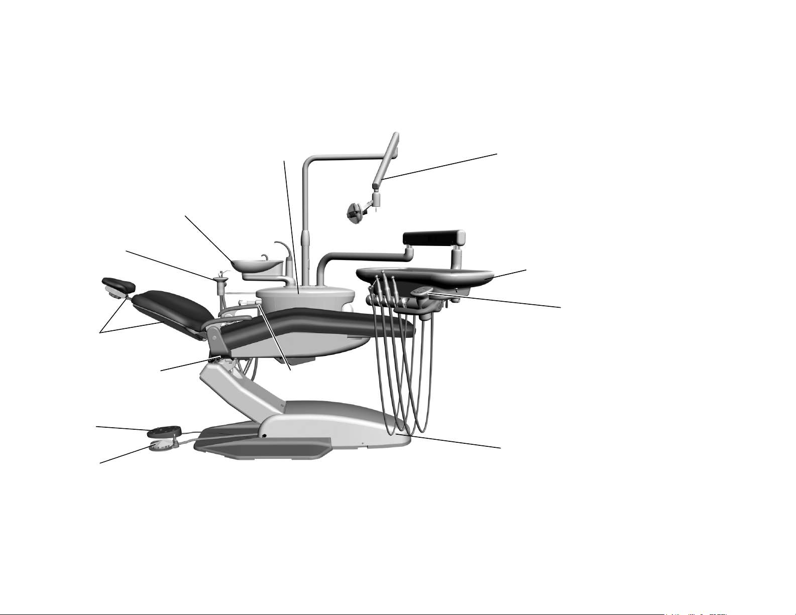
Cuspidor
(page 55)
Dental Chair
(page 7)
Assistant’s
Instrumentation
(page 63)
Foot Control
Footswitch
Solids Collector
(page 66)
Utilities
(page 73)
Support Center
(page 55)
Delivery System
(page 35)
Dental Light
(page 81)
Touchpad
(page 31)
Serial Number
Location
A-dec 200 System
A-dec 200 system comes configured as shown below:
Figure 1. A-dec 200 Systems
2 86.0016.00 Rev A
Page 11
Serial and Model Numbers
1
2
Introduction
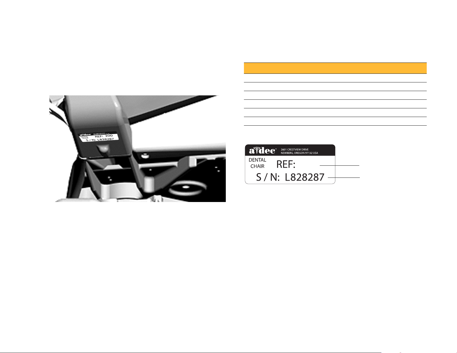
Product serial and model number information can be found on the serial/
model number labels. When you contact customer service, the serial
number helps identify the product and when it was manufactured.
Use Table 1 and Figure 2 to reference how to identify serial/model number
information.
Table 1. M o nt h I d e n t i fi c a t i o n Ta b le
Letter Month Letter Month
A January G July
B February H August
C March I September
DApril JOctober
E May K November
FJune LDecember
Figure 2. Serial Number Label Example
200
(1) The REF number is the model number. (2) The first letter of the serial number
indicates the month the product was manufactured. The first digit of the serial
number is the year of manufacture (for example, L8 = December 2008).
86.0016.00 Rev A 3
Page 12
A-dec 200 Service Guide
Service Tools
This table lists the types of tools available from A-dec for servicing A-dec 200 equipment and their recommended use:
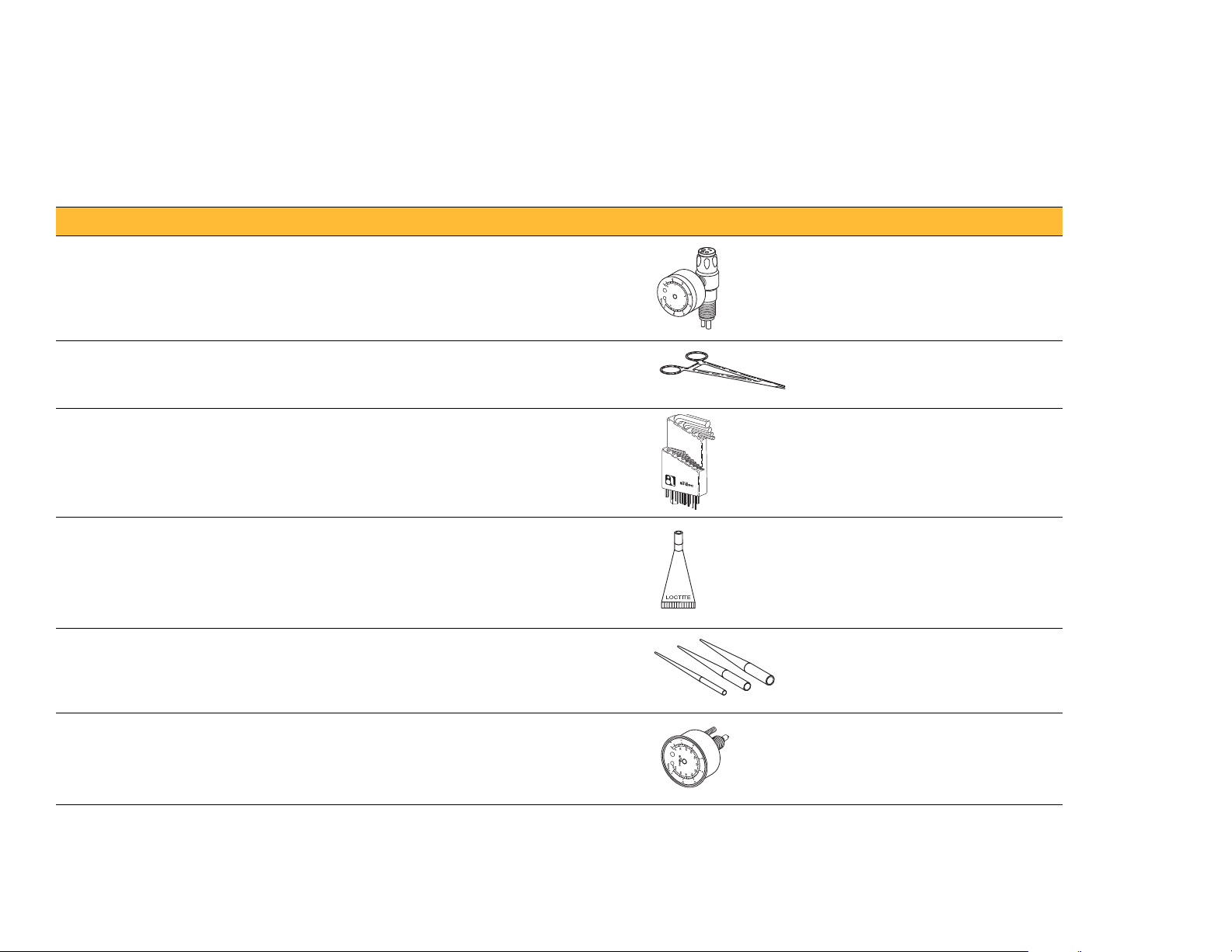
Table 2. Recommended Tools
Tool Tas k Part Illustration Part Number
Drive air pressure gauge Adjusting handpiece drive air pressure, 0-60 psi (4.13 bar)
This gauge does not fit the Borden 3-hole coupler
50.0271.00
Hemostat • Troubleshooting or repairing a unit
• Stopping air or water flow through tubing
Hex key set Servicing or installing A-dec equipment (plastic case included) 009.018.00
®
Loctite
O-ring tools Replacing O-rings during quick field repairs (fits the four
Panel mount gauge • Checking air/water pressure
Installing threaded fasteners to prevent loosening 060.001.00 (Red 271)
smallest O-ring sizes)
• Checking inline pressure gauge for testing purposes
009.008.00
060.002.00 (Blue 242)
009.013.00
026.118.00
4 86.0016.00 Rev A
Page 13
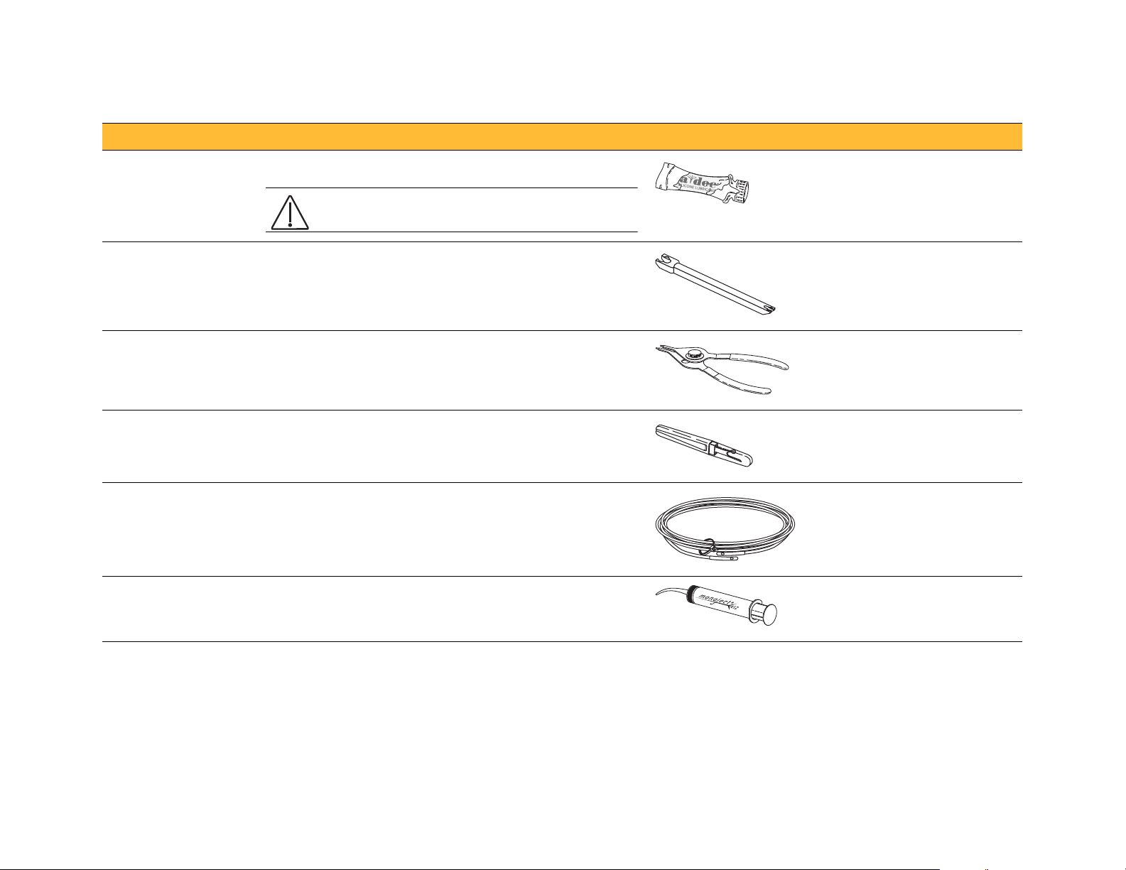
Table 2. Recommended Tools (continued)
CAUTION Use only A-dec Silicone lubricant or
the O-rings may be damaged.
Tool Tas k Part Illustra tion Part Nu mber
A-dec Silicone lubricant Lubricating internal moving parts such as O-rings, oral
evacuator valves, and bushings
Sleeve tool Aiding in securing 1/4" tubing sleeves and 1/8" uni-clamps 98.0072.00
98.0090.01
Introduction
Snap ring tool Installing and removing internal and external snap rings (fits
all snap rings used in A-dec equipment)
Tubing stripper Separating the extruded air and water lines in vinyl tubing 009.035.00
Umbilical stringer Routing additional tubing or wiring through existing umbilical
assemblies (12’ [3.66 meter] stringer with threading holes on
both ends)
Valve test syringe Testing of pilot operated valves; used to apply a static
pressure of 5-75 psi (.34-5.17 bar)
009.007.00
009.015.00
98.0050.01
86.0016.00 Rev A 5
Page 14

A-dec 200 Service Guide
6 86.0016.00 Rev A
Page 15
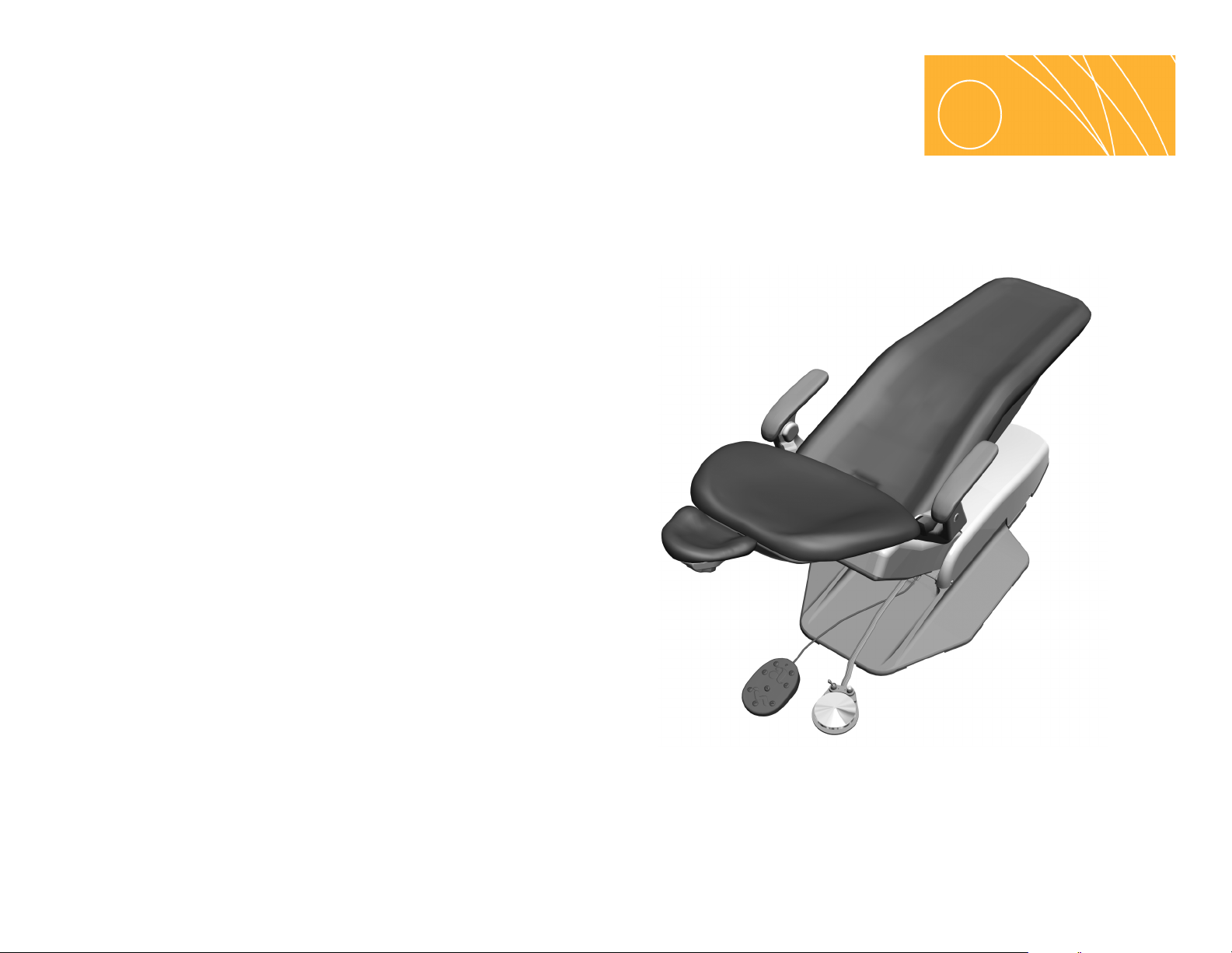
DENTAL CHAIR
2
This section provides detailed information related to service, maintenance,
and adjustment of the A-dec 200 dental chair.
Contents
• Product Overview, page 8
• Service, Maintenance, and Adjustments, page 10
• Illustrated Parts Breakdown, page 17
Figure 3. A-dec 200 Chair
86.0016.00 Rev A 7
Page 16
A-dec 200 Service Guide
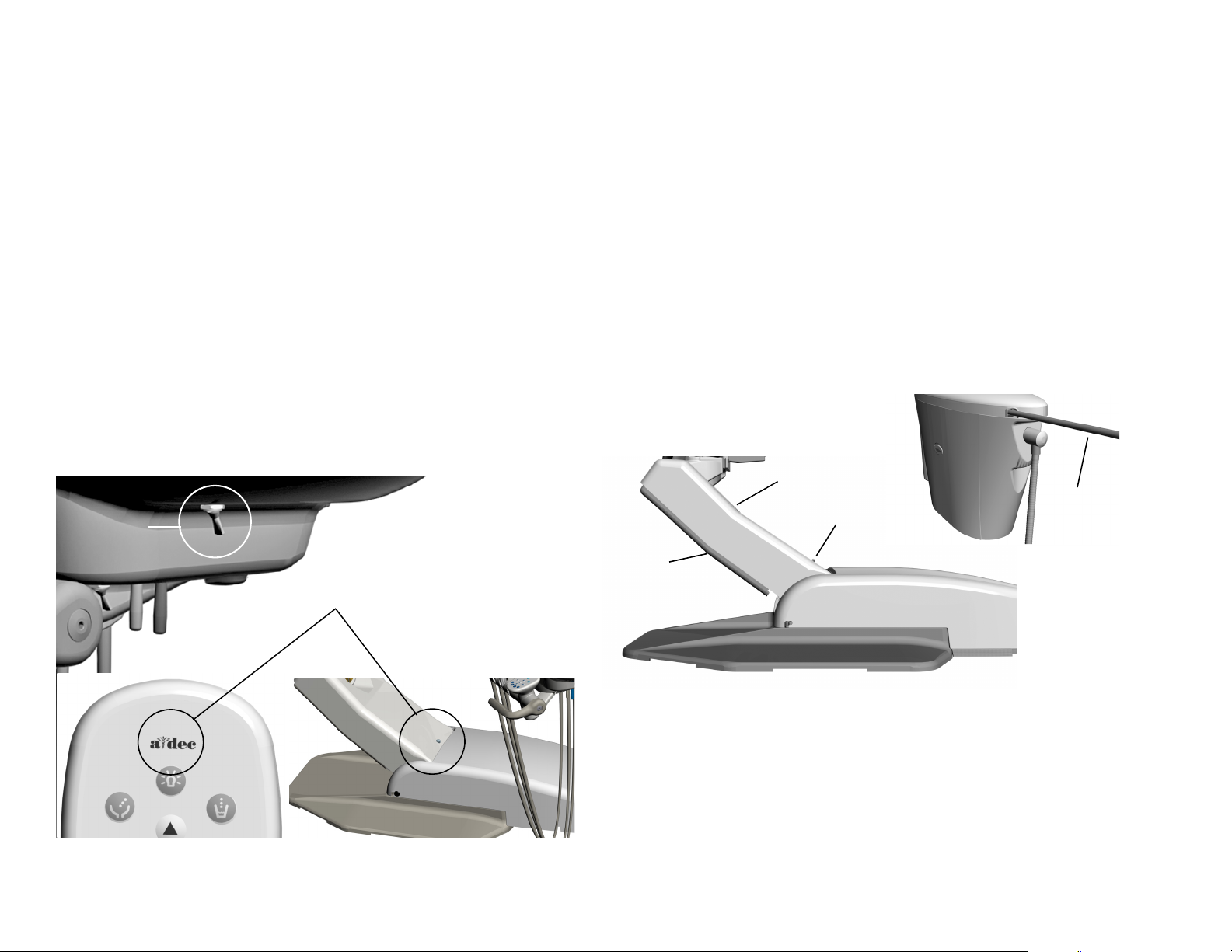
Master Toggle
(Power On/Off)
Status Light
Chair Lift Arm
Chair Stop
Plate
Status
Light
Assistant’s
Arm
Product Overview
Chair Load Capacity
Maximum Chair Capacity:
• Patient Load 136 kg (300 lbs.)
• Module/Accessory Loads (maximum off-center) with A-dec 200 system:
68 kg (150 lbs.) @ 406 mm (16")
Power and Status
The chair and system is controlled by the master toggle on the delivery
system. The power should always be turned off for service. When the Adec logo on the touchpad or the status light on the chair lift arm are
illuminated, the system is on and ready for use. If the status light blinks,
the limit switch has been activated.
Figure 4. Power and Status
Limit Switch and Chair Lockout
If anything becomes lodged under the chair lift arm or assistant’s arm, a
limit switch stops the downward motion of the chair. Pressing the chair
stop plate or lifting up on the assistant’s arm activates the limit switches.
Use the footswitch or touchpad to raise the chair, then remove the object.
The optional lockout kit inhibits the operation of the dental chair when a
handpiece is removed from its holder and the foot control pressed. When
this happens, the chair status light blinks quickly. To resume, replace the
handpiece and use the footswitch or touchpad to raise the chair.
Figure 5. Chair Lockout Overview
8 86.0016.00 Rev A
Page 17
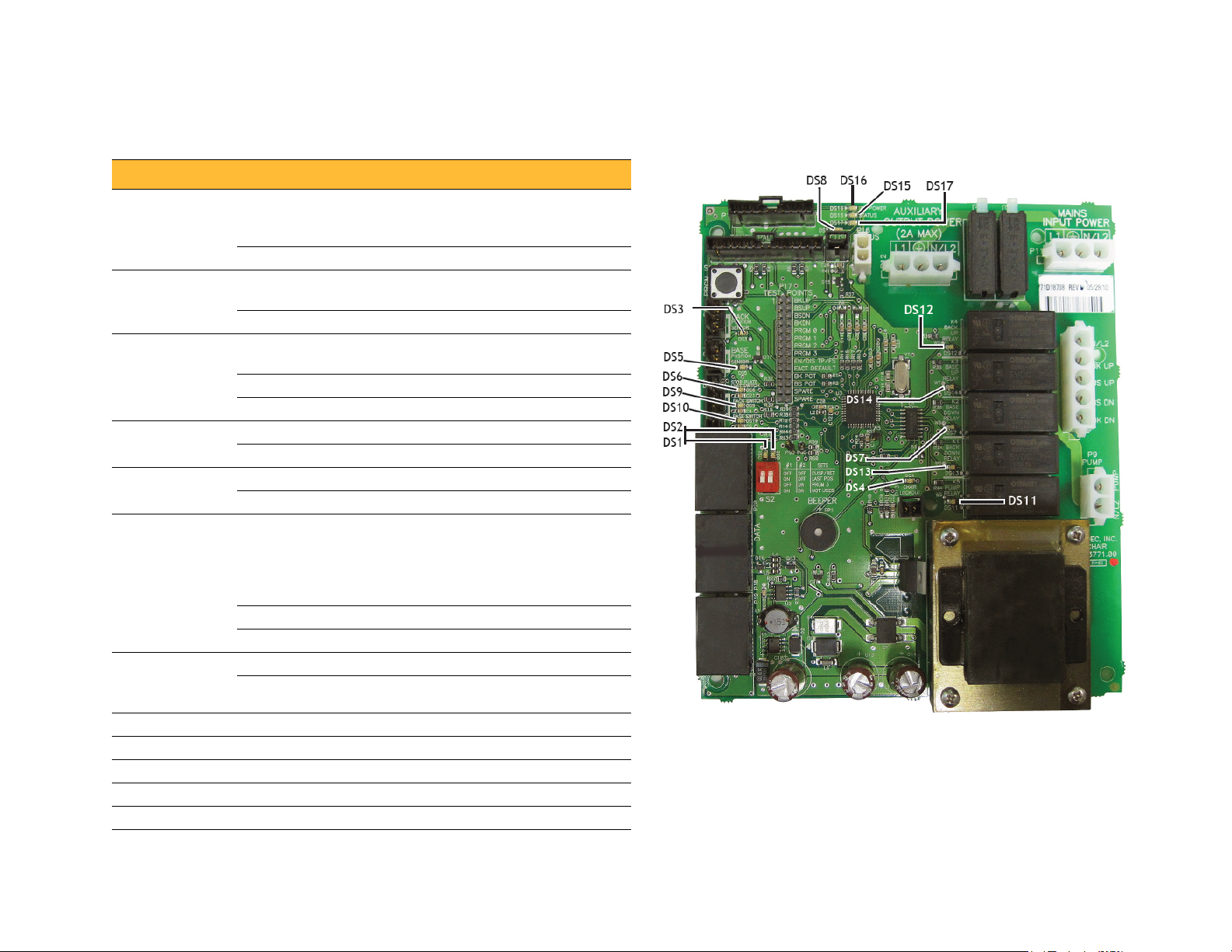
Circuit Board Components
Table 3. LED Identification Figure 6. Chair Circuit Board Components
LED Status Description
DS16 - AC power
LED
DS15 - Status LED Off System is not functioning, no power or
DS17 - Data LED Off No DCS communication, not connected
DS6 Stop plate
limit switch
DS4 - Chair
lockout
DS3 and DS5 -
Chair
potentiometers
DS7, DS13,
DS12, DS14
Chair relay LEDs
DS8 Capacitor switch
DS9 Back up limit switch
DS10 Base up limit switch
DS11 off = relay is off; on = relay is on
DS1, DS2 Position 3 function selection
Off No 24 VAC power, tripped circuit
breaker, power supply turned off, no
line voltage
Green, steady 24VAC at the terminal strip
circuit board has failed
Green, steady Normal operation
to the DCS, or DCS has failed
Green, steady Detects active DCS
Green, blinking Valid DCS Message
Off Closed, (normal)
Red Open, (activated)
Off Open, (normal)
Red Closed, (activated)
Off Potentiometer:
Not connected or bad connection
Moving in wrong direction
Limited range of motion, or
Cable is not on wheel
Yello w, steady Normal operation
Yello w, fast blink Upper end of travel
Off Relay is off
-
On Relay is on
Dental Chair
86.0016.00 Rev A 9
Page 18

A-dec 200 Service Guide
Service, Maintenance, and Adjustments
Contents
• Potentiometers, page 11
• Hydraulic System, page 13
• Solenoids, page 14
• Test the Motor Pump, page 15
• Headrest Adjustments, page 16
• Chair Speed Adjustments, page 16
Factory Default Routine
When a new circuit board is installed in the chair, factory default routine
needs to be run to learn the range of motion of the chair. The routine:
• Sets the base and back upper limits
• Calculates new presets based on actual range of motion of the chair
• Verifies that the potentiometers work
To start the factory default routine, place the “spare” jumper in the factory
default position on the P17 test points of the chair circuit board (see "Circuit
Board Components" on page 9 for reference).
When running the factory default routine the chair:
1. Moves base down
2. Moves base up
3. Moves back down
4. Moves back up
5. Moves base and back to Position 0
6. Beeps three times
NOTE The jumper must remain in the factory default
position to complete the factory default routine. The status
LEDs on the standard and deluxe touchpads and the chair
circuit board double blink while the factory default routine
is running and after the routine is complete.
10 86.0016.00 Rev A
Page 19
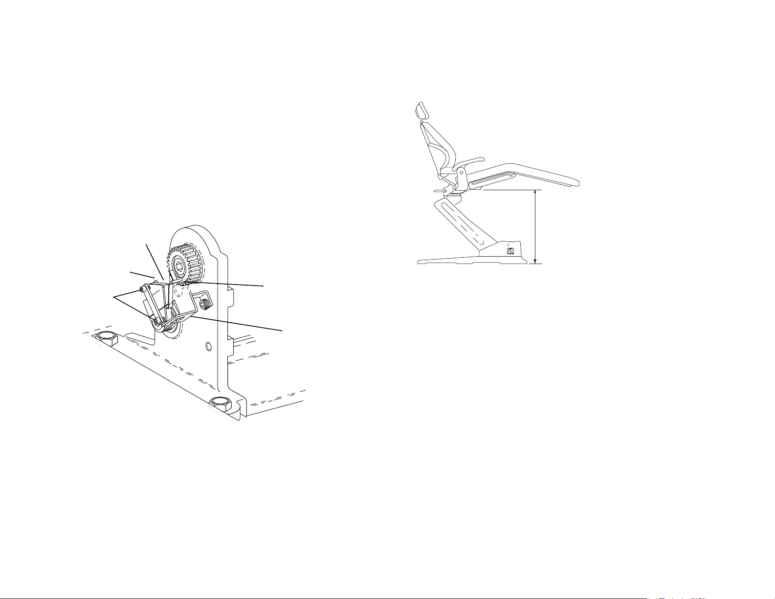
Potentiometers
Actuator Pin
Switch Arm
Limit Switch
Mounting
Bracket
Clamping
Screws
25"
63.5 cm
Potentiometers provide the controller with current position values for the
chair base and back. The controller saves the chair values when
programmed and compares the values with current position values for the
pre-position and auto-return functions.
Adjust the Base Up Limit Switch:
1. Remove the motor pump cover.
2. Loosen the two screws clamping the limit switch to the mounting
bracket.
Figure 7. Mounting Bracket
Dental Chair
Figure 8. Chair Position
4. Push the limit switch against the actuator on the drive gear until the
switch opens (clicks), then tighten the clamping screws. (See Figure 7).
5. Position the chair base down until the limit switch has closed, then
position the chair full base up. Check the distance between the top of
the base plate to the flat area around the threaded stud the chair adapter
mounts to. If the distance is incorrect, repeat steps 2 through 4.
3. Position the chair as shown in Figure 8.
86.0016.00 Rev A 11
Page 20
A-dec 200 Service Guide
Potentiometer
Gear
Positioning
Potentiometer
Limit Switch
Mounting
Screw
Large Drive
Gear
Limit Switch
Mounting Screws
Bracket Mounting
Screws
Switch Arm
Drive Shaft
Urethane Tubing
3/8" OD
Potentiometer
Shaft
Tip
Potentiometer
Shaft
Clockwise
Counterclockwise
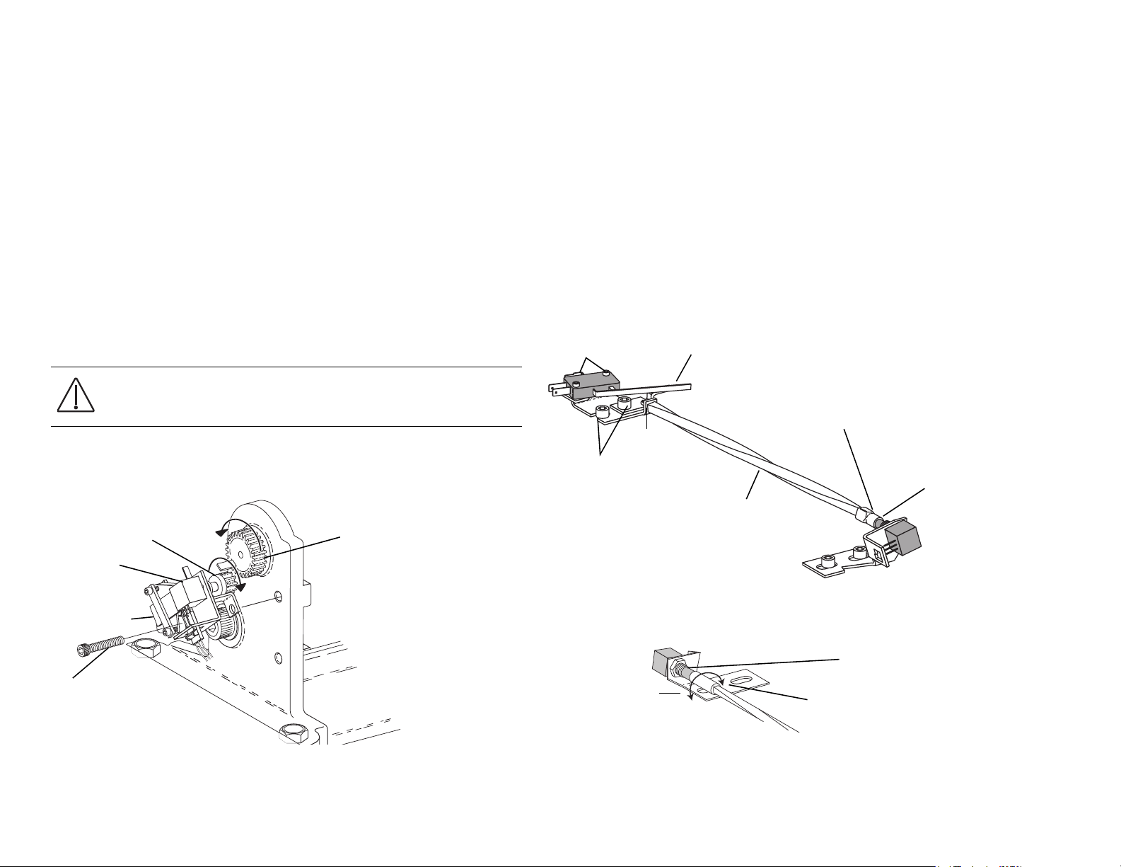
Adjust the Base Positioning Potentiometer
1. Remove the motor pump cover and position the chair base down.
2. Use a 3/16" hex key to remove the limit switch and mounting screw. See
Figure 9.
3. Turn the potentiometer gear counterclockwise until it stops.
4. Align the potentiometer assembly, then turn the potentiometer gear
clockwise two teeth.
5. Reinstall the limit switch and potentiometer assembly. Make sure the
potentiometer gear does not turn and the two gears mesh properly.
6. Ensure that the electrical connections to the limit switch and positioning
potentiometer are property set.
7. While observing the two gears for binding, lower the chair base.
CAUTION Do not raise to the full base up position until after you
have checked the base up limit switch for proper adjustment. the
chair may go into hydraulic lock if not adjusted properly.
8. Reinstall the cover, and program the auto-positioning functions.
Figure 9. Base Potentiometer
Adjust the Back Potentiometer
1. Position the chair back to its full up position.
2. Disconnect the limit switch wiring harness from the limit switch.
3. Remove the limit switch mounting screws and limit switch from the
bracket. Do not bend the switch arm.
4. Remove the bracket mounting screws.
5. Remove the drive shaft from the potentiometer shaft.
6. Remove the drive shaft from the chair by moving it toward the chair
backrest, and slightly to the side to dislodge it from the holder.
Figure 10. Remove Drive Shaft
12 86.0016.00 Rev A
7. Turn the potentiometer shaft clockwise until it no longer turns, then
turn the shaft counterclockwise 1/8" of a turn
Figure 11. Adjust Back Potentiometer
8. Reinstall the shaft.
Page 21
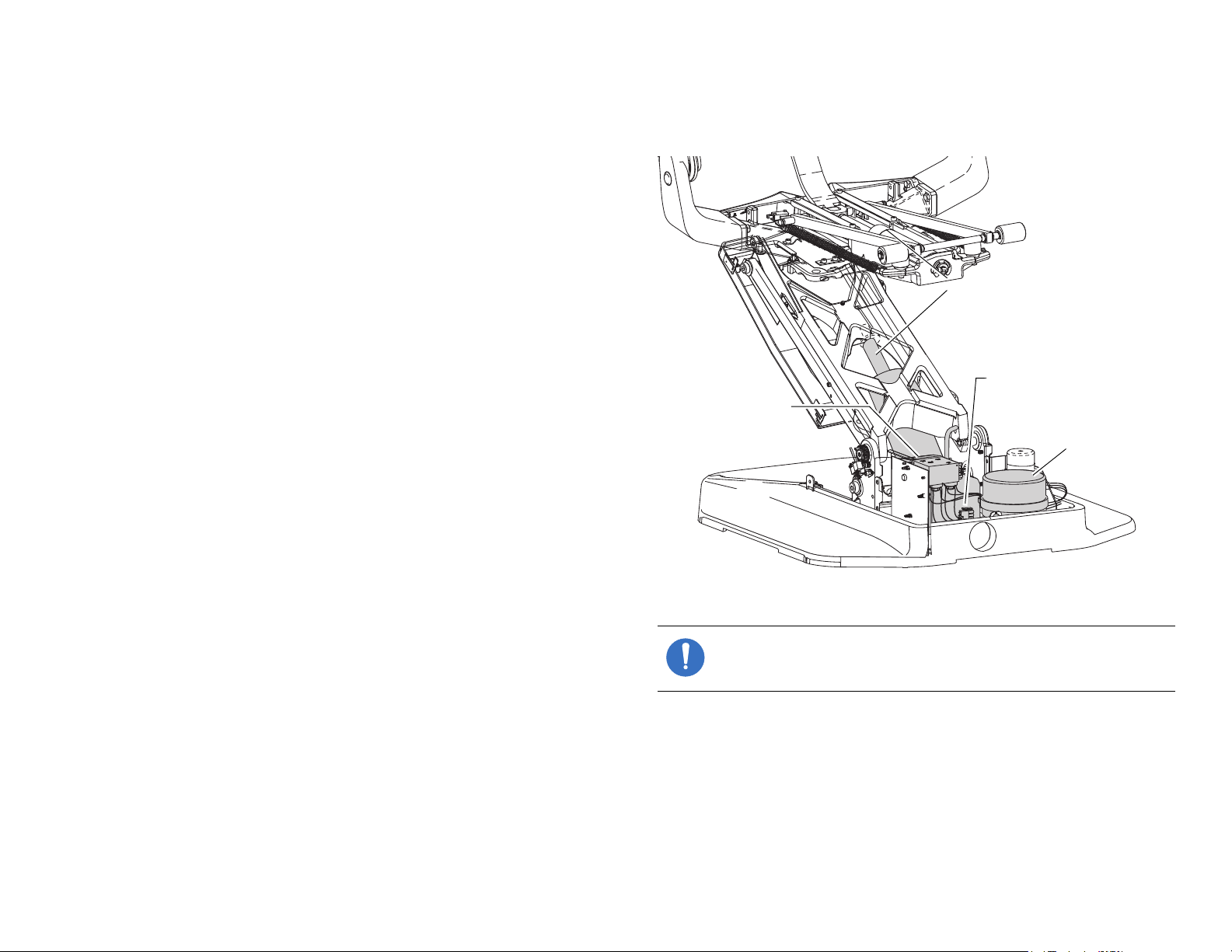
Hydraulic System
Hydraulic Cylinders
Hydraulic Fluid Reservoir
Solenoid/Manifold
Assembly
Motor Pump
The hydraulic system consists of:
• Hydraulic fluid reservoir
The fluid level in the reservoir can be seen through the sides of the
reservoir and is serviced via a top fill cap.
•Hydraulic cylinders
The hydraulic cylinders control the base lift and back functions. Springs
and gravity retract the rod during base and back down functions.
• Motor-driven hydraulic pump
The hydraulic pump and the starter capacitor supply hydraulic fluid
from the reservoir, under pressure, to the chair lift and tilt hydraulic
cylinders for back up and base up functions.
• Solenoid/manifold assembly
This assembly gates hydraulic fluid to and from the two cylinders.
Depending on the chair function called for, the controller selects which
solenoid-actuated manifold valves are opened or closed. The solenoid/
manifold assembly also includes four adjustable needle valves used to
restrict or divert the flow of hydraulic fluid to and from the lift and tilt
cylinders. These valves provide the rate of travel adjustment for chair
base and back movement.
Dental Chair
Figure 12. Hydraulic System
86.0016.00 Rev A 13
NOTE If cable ties are present in the product and you need to
remove them for servicing, make sure to replace the ties after
service is completed.
Page 22
A-dec 200 Service Guide
Hydraulic
Manifold
O-ring
Poppet
Poppet
Sleeve
Washer
Solenoid
ID Washer (Solenoid
Specifications)
P10
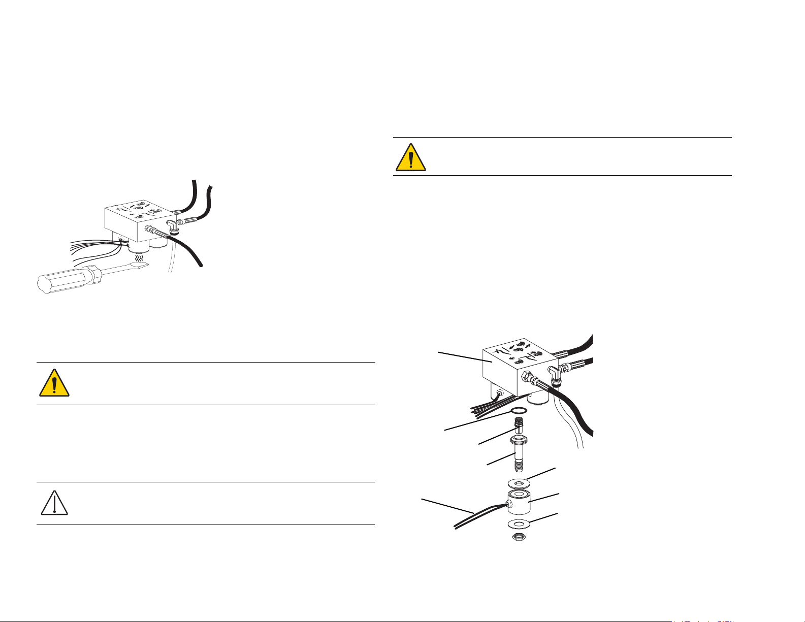
Solenoids
Tes t th e Sol eno i d
To test the magnetic pull of the solenoid hold the tip of screwdriver near a
solenoid and activate the appropriate chair function. You should feel the
tug of the magnetic field generated around the solenoid.
Figure 13. Test the Solenoid
Remove and Replace the Solenoid
1. Lower the chair base and back to the full down position. Remove the
motor pump cover, then unplug the chair.
WARNING The solenoid coils are powered by line voltage (100,
120, or 240 V). Failure to unplug the chair may result in serious
injury from electrical shock.
4. Using a flat-tipped screwdriver, loosen and then remove the sleeve and
poppet from the manifold assembly.
WARNING To prevent the possibility of over-heating and failure,
replace the entire solenoid assembly.
5. Remove the o-ring from inside the manifold, and install a new o-ring.
6. Install a new sleeve and poppet; tighten the poppet sleeve using a flat-
tipped screwdriver.
7. Install a new coil on the plunger. Do not overtighten the retaining nut.
8. Strip approximately 1/4" of insulation from the wires cut in step 2, and
install a crimp-on butt-type connector on each wire.
9. On the new solenoid, cut the wiring to length allowing enough to reach
the crimped-on connectors. Strip approximately 1/4" of insulation from
the wires and crimp each wire into a connector.
Figure 14. Remove and Replace Solenoid
2. Using a pair of wire cutters, cut the wiring to the faulty solenoid at
3. Using a 9/16" wrench, remove the solenoid retaining nut and slide the
14 86.0016.00 Rev A
about mid point between the solenoid and connector P10.
coil off the poppet sleeve.
CAUTION Use caution when removing and replacing the coil. The
poppet sleeve is easily bent. Even slight bending of the sleeve will
result in the malfunction of the solenoid valve.
Page 23
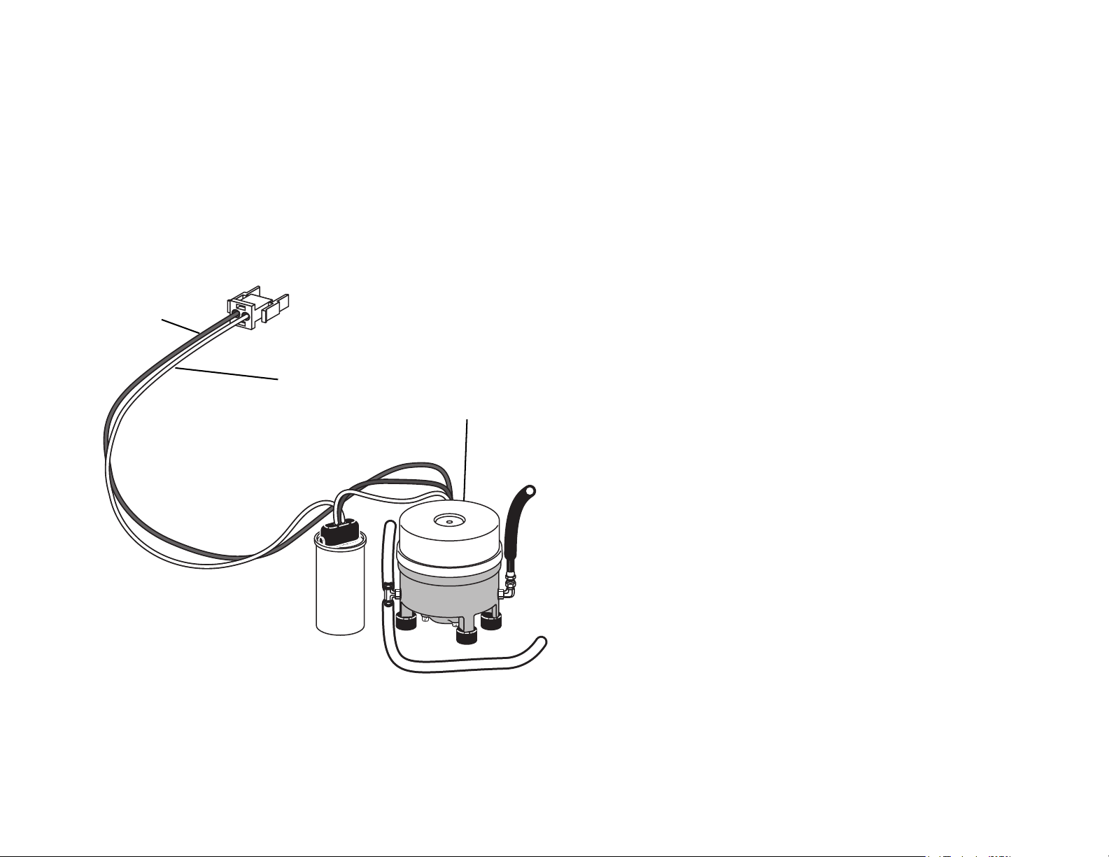
Tes t t he Mot or Pu mp
Red Wire
White Wire
Motor Pump
This test requires the use of a current pickup probe.
• Clip the probe onto the red wire going to the motor pump.
• Use the footswitch or touchpad to raise the chair.
You should read 5 Amps (maximum) of current for 120 V motor pump, or
2.5 Amps (maximum) of current for 240 V motor pump.
Figure 15. Test Motor Pump
Dental Chair
86.0016.00 Rev A 15
Page 24
A-dec 200 Service Guide
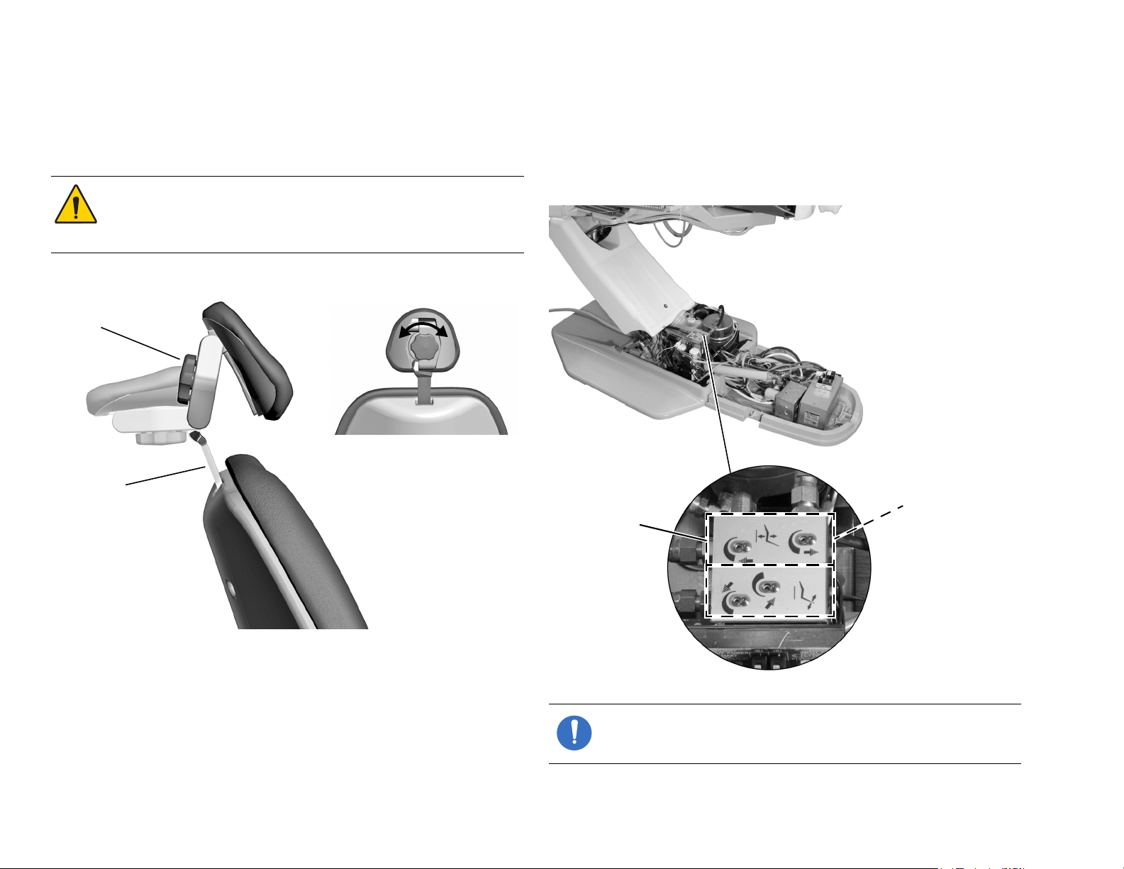
Glide Bar
Locking
Knob
Adjust chair
base speed.
Adjust chair
back speed.
Headrest Adjustments
Turn the locking knob clockwise to lock it into the desired position. Slide
the headrest and glide bar up or down to adjust the height.
WARNING When the glidebar has reached its maximum
recommended working height, a warning will be visible on the
patient’s side of the glide bar. Do not use the headrest in a position
where this warning is visible.
Figure 16. Headrest Adjustments
Chair Speed Adjustments
The speed for moving the chair seat and back can be adjusted. Use a 3/32"
hex key to adjust the chair base speed and back speed on the manifold (see
Figure 17. Adjust Manifold for Chair Speed
NOTE If cable ties are present in the product and you need to
remove them for servicing, make sure to replace the ties after
service is completed.
16 86.0016.00 Rev A
Page 25
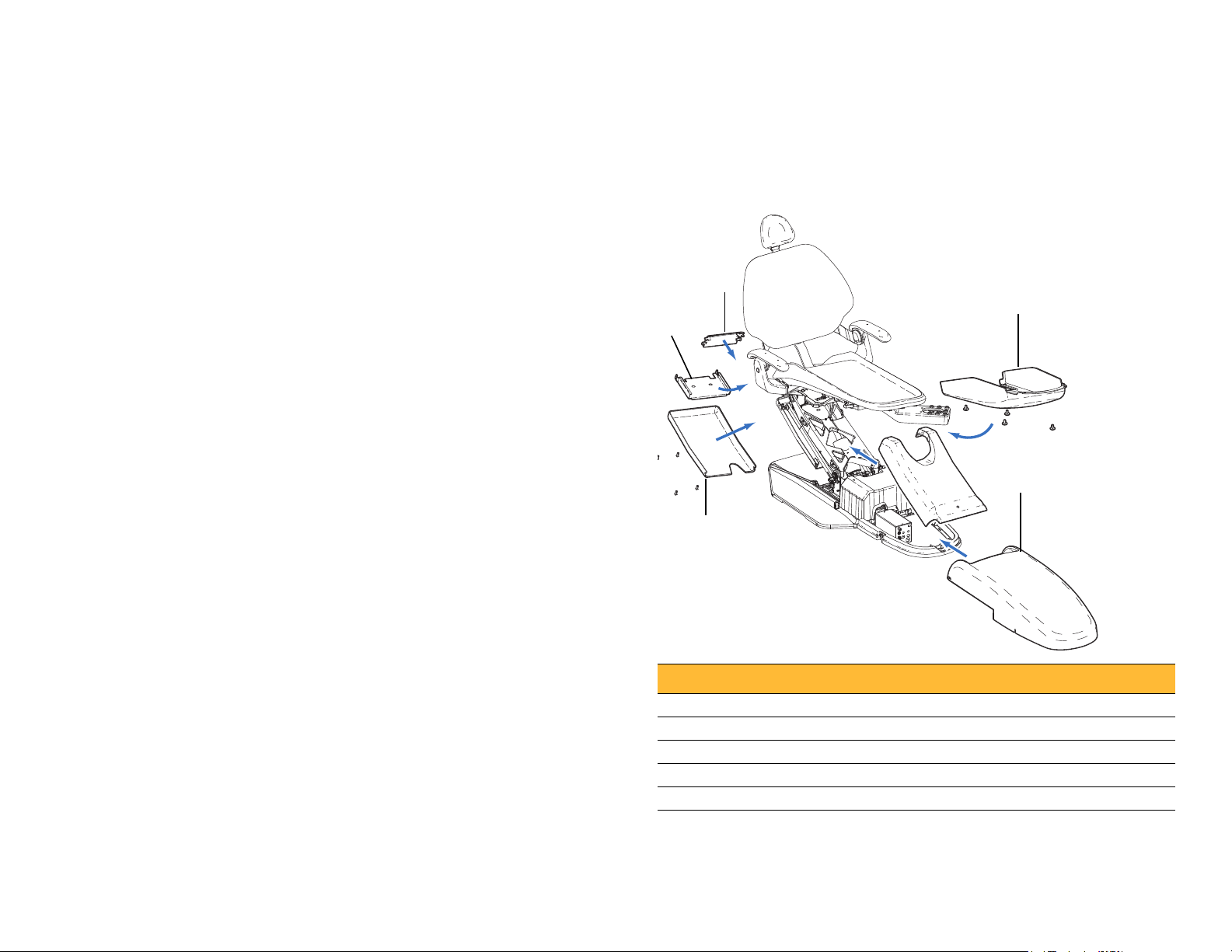
Illustrated Parts Breakdown
3
1
5
4
2
Dental Chair
Part Identification
In this section, you will find serviceable components tables that correspond
to the illustrations. The tables identify all parts and kits, including those
that are not for sale. Parts that are not for sale are indicated with the symbol
shown below:
Chair Covers
Figure 18. A-dec 200 Dental Chair
†— Indicates that the individual part is not available for sale. These parts
are typically part of a kit and/or larger assembly that is for sale.
Contents
• Chair Covers, page 17
• Upper Chair Assembly, page 18
• Mid Chair Assembly, page 20
• Lower Chair Assembly, page 22
• Headrest Assembly, page 23
• Motor Pump and Capacitor Assembly, page 24
• Hydraulic Manifold Assembly, page 26
• Hydraulic Tank Assembly, page 27
• Base Limit Switch Assembly, page 27
• Back Potentiometer Assembly, page 28
• Base Position Potentiometer Assembly, page 29
Item Part Number Description
1 61.3821.00 Rear chair cover
2 61.3847.00 Bottom cover
3 61.3846.00 Utility cover
86.0016.00 Rev A 17
4 61.2239.01 Lift arm cover
5 61.2242.00 Umbilical routing bracket
Page 26

A-dec 200 Service Guide
Upper Chair Assembly
Item Part Number Description
1 — Double articulating headrest assembly (see page 23)
2 61.3824.00 Backrest cover
3 61.3791.00 Armrest release button
4 013.052.00 Compression spring, .843 OD X 1.375 FL
5 61.1245.02 † Arm support, LH
6 004.157.00 Wave spring washer, .990 OD stainless steel
7 004.126.00 Flat washer
8 61.3827.00 Armrest cover
9 61.3790.01 Armrest pivot plate, LH
10 005.123.01 Button head socket screw, 10-32 X 5/8"
11 61.3108.00 Flanged bearing
12 001.164.00 Socket shoulder screw, 1/2-13 X 5/8 X 5/8
13 61.3788.01 Pivot bolt cover
14 61.2740.00 Backrest link pin
15 016.131.00 Flanged bearing
16 007.069.00 Set screw, socket 1/4-20 X 1/4
17 61.3792.00 Back link
18 61.3789.01 Armrest pivot plate, RH
19 005.147.00 Flat head socket screw, 1/4-20 X 1-1/4
20 006.122.01 Retainer nut, 10-32 zinc
21 61.2743.00 Brake shoe
22 61.1247.02 † Arm support, RH
23 001.268.00 Socket screw, 1/4-20 X 3/30 mm stainless steel
24 002.136.00 Flat head socket screw, 1/4-20 X 1/38
† Indicates that the individual part is not available for sale
18 86.0016.00 Rev A
Page 27
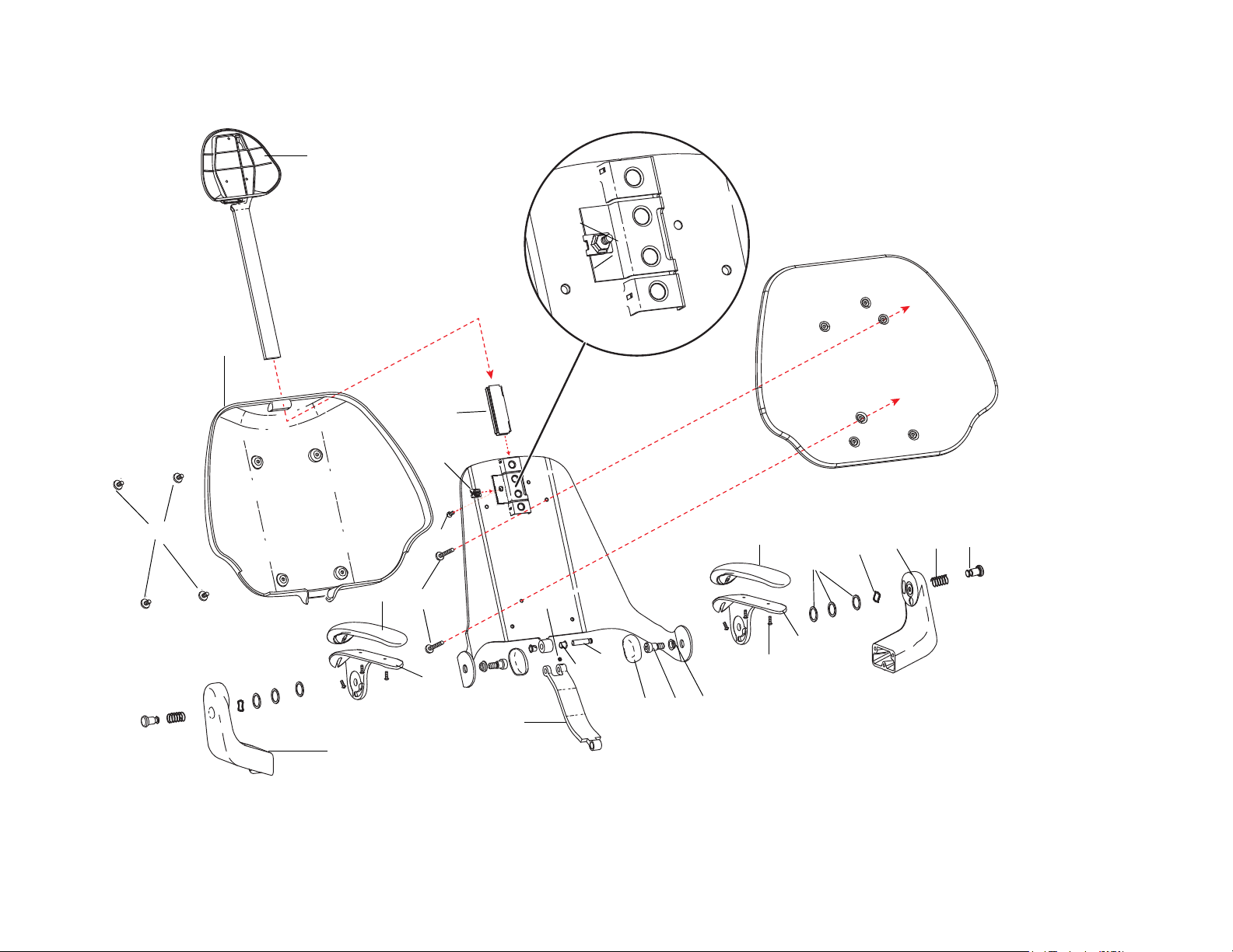
Figure 19. Upper Chair Assembly
2
1
Headrest Assembly
(see page 23)
6
5
4
3
10
11
12
13
16
14
15
17
18
22
23
19
20
21
8
9
7
8
20
21
24
Dental Chair
86.0016.00 Rev A 19
Page 28

A-dec 200 Service Guide
Mid Chair Assembly
Item Part Number Description Item Part Number Description
1 61.1309.00 Tilt slide block 21 35.1749.00 Chair mount adaptor
2 61.1311.00 Tilt cylinder clevis rod 22 004.171.00 Thrust washer
3 61.1267.00 Tilt cylinder assembly 23 006.124.00 5/8-18 UNF-2B ESNA 4N zinc
4 010.031.00 E-clip 24 025.072.00 Cable tie mounting block
5 61.2076.00 Roller arm link 25 005.143.00 Button head socket screw, 1/4-20 X 3/8"
6 61.2078.00 Toeboard axle 26 61.1294.00 † Lower structure link
7 61.2293.00 Linkarm roller 27 41.1145.00 Umbilical support
8 005.008.01 Socket head screw, 1/4-20 X 1/2" 28 41.1143.00 Umbilical restraint
9 025.044.00 Clamp 29 61.2095.00 † Lift arm
10 61.1308.00 Channel guide 30 004.149.00 Flat neoprene washer, .680 ID
11 013.054.00 Spring 31 004.104.00 Flat steel plated washer, .640 ID
12 002.134.00 Socket head screw, 1/4-20 X 1/4" 32 — Lift cylinder
13 61.1221.00 Base limit switch assembly 33 61.1285.00 Lift pin
14 61.1224.00 Back position potentiometer assembly 34 011.046.00 Clip pin
15 002.023.00 Head screw, 3/8-16 X 1-1/4 35 41.1144.00 Umbilical retainer
16 61.1314.00 Wear pad 36 001.165.00 Socket head shoulder screw
17 002.120.00 Socket head patch screw, 1/4-20 X 1" stainless steel 37 001.164.00 Socket head shoulder bolt
18 004.148.00 Flat nylatron washer, .630 ID 38 61.3825.00 † Swivel bracket
19 — Seat armature 39 61.3826.00 † Upper structure, gray 3
20 61.1270.00 Stud
† Indicates that the individual part is not available for sale
20 86.0016.00 Rev A
Page 29
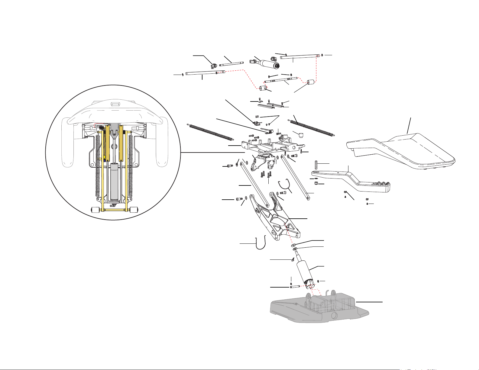
Figure 20. Mid Chair Assembly
2
3
4
Lower Chair
(see page 22)
1
5
4
4
6
7
7
5
4
8
9
10
11
13 Base Limit Switch
(see page 27)
12
15
16
4
4
17
18
20
21
22
23
24
25
26
27
28
29
30
31
32
33
34
35
36
18
18
18
18
37
26
38
39
14 Back Potentiometer
(See page 28)
19
Dental Chair
86.0016.00 Rev A 21
Page 30
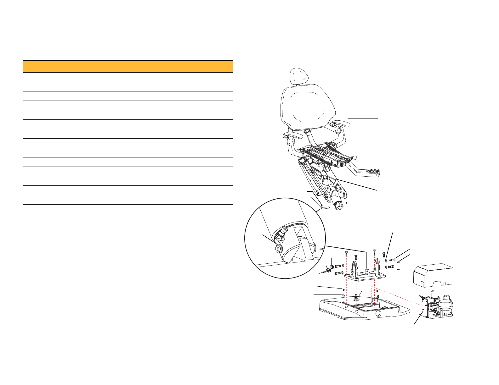
A-dec 200 Service Guide
Motor Pump Assembly (see page 24)
1
2
1
2
34
5
6
7
8
9
10
11
12
13
14
Upper Chair Assembly
(see page 18)
Mid Chair Assembly
(see page 20)
Lower Chair Assembly
Item Part Number Description
1 010.031.01 E-clip
2 61.1285.00 Pivot pin
3 001.163.00 Hex head cap screw, 1/2-13 X 1-1/4
4 004.148.00 Flat nylatron washer, .630 ID
5 001.165.00 Socket head shoulder screw
6 005.008.01 Socket head screw, 1/4-20 X 1/2
7 61.1277.01 † Sub base
8 61.3848.00 Floorbox/pump cover
9 61.1650.00 Foot switch/foot control bracket
10 61.2037.01 Baseplate
11 61.1286.00 Bracket
12 005.143.00 Button head socket screw, 1/4-20 X 3/8
13 61.1221.00 Base position potentiometer assembly
14 61.1295.00 Gear
Figure 21.
Lower Chair Assembly
† Indicates that the individual part is not available for sale
22 86.0016.00 Rev A
Page 31

Headrest Assembly
1
2
3
7
4
56
8
9
10
14
11
12
15
13
14
Item Part Number Description Item Part Number Description
1 61.1232.02 Knob, locking headrest 9 61.2121.00 Clamp bar
2 004.061.00 Washer 10 61.2190.00 Pivot block
3 016.129.00 Bearing, thrust needle, .500 ID 11 61.2248.00 Pivot shaft
4 005.124.00 Button head screw, 10 - 32 x 1 12 61.2338.00 Pivot pin
5 61.3762.01 Cover, front 13 61.3762.01 * Rear cover
6 61.2172.00 Tube spacer 14 61.0816.00 Bushing
7 004.136.00 Washer, thrust bearing, .500 ID 15 61.2267.00 Cushion back cover
8 61.1272.00 † Glidebar
† Indicates that the individual part is not available for sale
* Sold as a matching set
Figure 22. Headrest Assembly
Dental Chair
86.0016.00 Rev A 23
Page 32

A-dec 200 Service Guide
Motor Pump and Capacitor Assembly
Item Part Number Description
1 61.1339.00 Hydraulic tank
2 002.052.00 Pan head phillips screw, 10-32 X 3/8
3 004.118.00 Nylatron washer, .188 ID
4 004.230.00 Stainless steel washer, .203 ID
5 041.529.00 Boot
6 041.627.00 Capacitor, 50 UF 240 V, 50/60 HZ
7 001.164.00 Screw
8 61.1327.00
61.1328.00
9 002.100.01 Socket head screw, 6-32 X 1-1/4
10 61.1338.00 Motor pump tray
11 61.1332.00
61.1333.00
61.1334.00
12 041.428.00 Standoff
13 90.1029.02 Chair circuit board, 100-240 Volt
Motor pump assembly, 100/100-115 V
Motor pump assembly, 240 V
Hydraulic manifold assembly, 100 Volt
Hydraulic manifold assembly, 120 Volt
Hydraulic manifold assembly, 240 Volt
24 86.0016.00 Rev A
Page 33
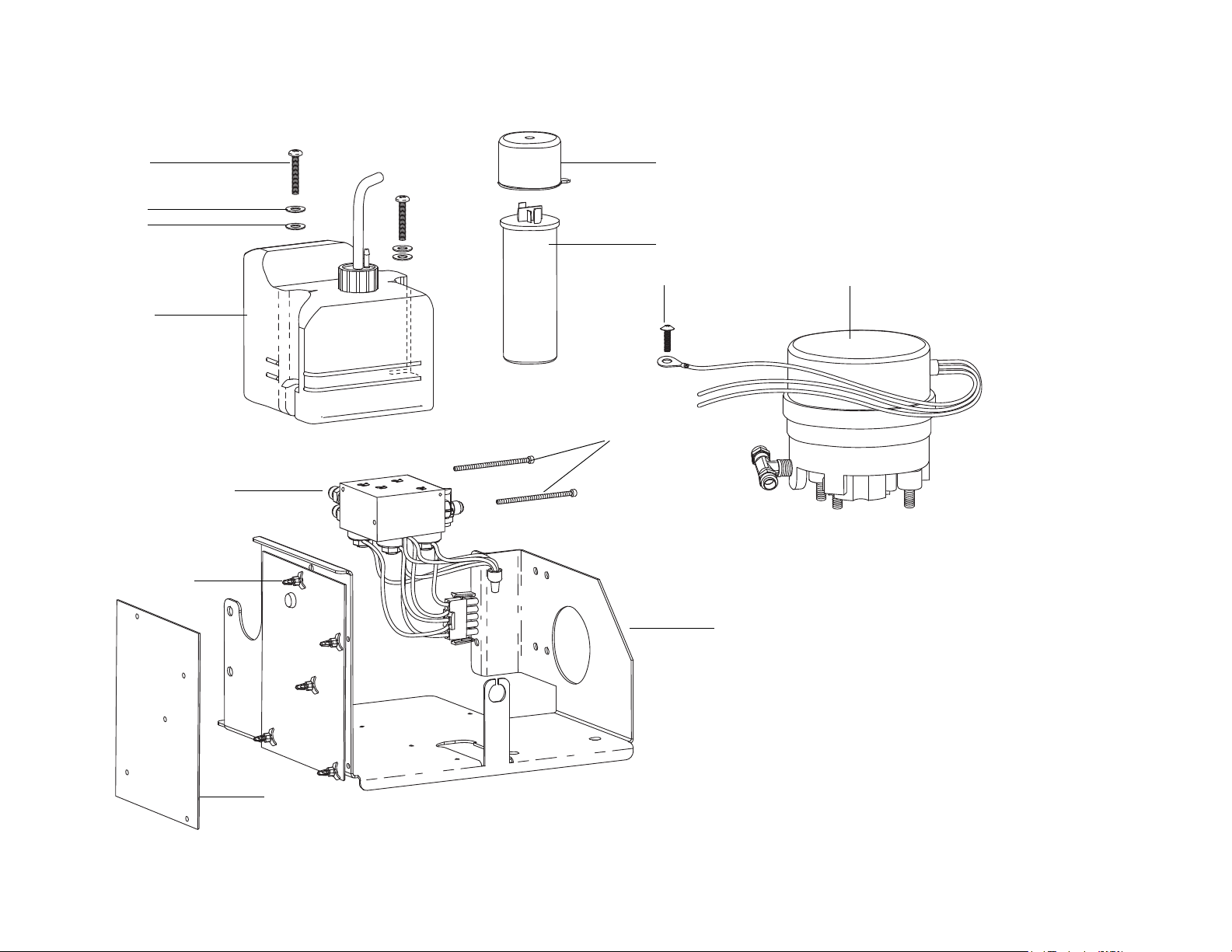
Figure 23. Motor Pump and Capacitor
1
5
6
7
8
2
9
10
11
12
13
3
4
Dental Chair
86.0016.00 Rev A 25
Page 34

A-dec 200 Service Guide
1
2
3
3
4
5
6
Hydraulic Manifold Assembly
Item Part Number Description Item Part Number Description
1 002.118.02 Screw, button head socket 4 61.1335.00
61.1336.00
61.1337.00
2 61.0460.00 Flow adjust screw with o-ring 5 030.015.02 O-ring, package of 10
3 030.004.02 O-ring, AS568-004 package of 10 6 61.1333.00
61.1334.00
Figure 24. Hydraulic Manifold
Solenoid, 8-watt, 100 V, yellow wires
Solenoid, 8-watt, 120V, black wires
Solenoid, 8-watt, 240 V, red wires
Manifold assembly, hydraulic, 120 V
Manifold, assembly, hydraulic, 240V
26 86.0016.00 Rev A
Page 35

Dental Chair
2
43
1
2
3
Hydraulic Tank Assembly
Item Part Number Description
1 006.112.00 Retainer Nut, 3/4"
2 61.1489.00 Pick-Up Tube Solder Assembly
3 004.161.00 Rubber Washer
4 61.1339.00 Hydraulic Tank
Figure 25. Hydraulic Tank Assembly
Base Limit Switch Assembly
Item Part Number Description
1 001.021.00 Socket Head Screw, 4040 X 1/2 Stainless Steel
2 044.184.00 Switch, 15 Amp 125 Volt
3 61.1315.00 Mounting Bracket
Figure 26. Base Limit Switch Assembly
86.0016.00 Rev A 27
Page 36

A-dec 200 Service Guide
1
2
3
4
5
Back Potentiometer Assembly
Item Part Number Description
1 61.1225.00 Helical Drive Shaft
2 025.113.00 Compression ring
3 002.134.00 Socket Head Screw, 1/4-20 X 1/4
4 041.372.00 Potentiometer, 5 K Ohm
5 61.1226.00 Mounting Bracket
Figure 27. Back Potentiometer
28 86.0016.00 Rev A
Page 37

Base Position Potentiometer Assembly
1
2
3
4
5
6
7
8
Item Part Number Description
1 002.024.00 Socket Head Screw, 4-40 X 3/4
2 60.0080.00 Mounting Plate
3 041.372.00 Potentiometer, 5 K Ohm
4 61.1223.00 Base Position Mounting Bracket
5 044.184.00 Switch, 15 Amp, 125 Volt
6 61.1367.00 Limit Switch Mounting Plate
7 002.120.00 Socket Head Patch Screw, 1/4-20 X 1 Stainless Steel
8 61.2625.00 † Gear, 10 Tooth, 24 Point
† Indicates that the individual part is not available for sale
Figure 28. Base Potentiometer
Dental Chair
86.0016.00 Rev A 29
Page 38

A-dec 200 Service Guide
30 86.0016.00 Rev A
Page 39

PROGRAMMING
Touchpad
Footswitch
3
The A-dec 200 product offers the option of having a standard touchpad.
The touchpad centralizes treatment room controls into one touch surface
including the chair, light, cuspidor controls, and auxiliary equipment.
NOTE
• The A-dec 200 product ships with a non-functioning cuspidor
board. If the system has a touchpad and cuspidor, an upgrade
to the cuspidor board is required to allow control of the
cuspidor functions with the touchpad.
• If the system has a touchpad and dental light, the dental light
circuit board is required (located in the floor box) to allow
control of the dental light from the touchpad.
Figure 29. Touchpad or Footswitch Programming
86.0016.00 Rev A 31
Page 40

A-dec 200 Service Guide
Entry/Exit
Treatment 1
Treatment 2
Program Button
X-ray/Rinse
Program Button
X-ray/Rinse
Treatment 2
Entry/Exit
Treatment 1
Touchpad
To u c h p a d O p t i o n s
The A-dec logo on the touchpad indicates the system status. If it appears as
solid blue, the system is on and ready for use.
Chair Positions
The chair direction arrows on the standard and deluxe touchpads allow
you to manually move the chair base up/down and back up/down. Table
lists the icons and the action of each icon.
Figure 30. Chair Position Touchpad Button
Footswitch
Table 4. Chair Preset Positions
Footswitch/Touchpad Description
Entry/Exit: Positions chair for patient entry/exit. On
systems with a doctor’s touchpad, it also turns the
dental light off.
Treatment 1: Positions the chair base and back down.
On systems with a doctor’s touchpad, it also turns the
dental light on.
Treatment 2: Positions the chair base down and back
up. On systems with a doctor’s touchpad, it also turns
the dental light on.
X-ray/Rinse: Moves the chair for either x-ray or rinse
position. Press again to move the chair to the previous
position. On systems with a doctor’s touchpad, also
turns the dental light off or back on.
Chair Preset Buttons
Use the program buttons to assign and save chair preset positions. To
program the chair presets Entry/Exit, Treatment 1, and Treatment 2:
1. Use the manual controls to adjust the chair position as desired.
2. Press and release the Program button. One beep indicates programming
mode is on.
3. Within four seconds, press the chair position button you wish to reset
(for example and ). Three beeps indicate the new setting is
programmed into memory.
Chair Preset Position Buttons
Chair position buttons are factory preset to automatically move the chair
(see Figure 30).
32 86.0016.00 Rev A
X-Ray/Rinse Button
The x-ray/rinse preset button moves the chair and patient into an upright
position for x-rays or cuspidor access. To change the function to an
additional programmable chair position:
Page 41

1. On the touchpad or footswitch, press and hold the power button and
Dental Light
Button
LED
Indicator
the x-ray/rinse button at the same time for three seconds.
○ One beep indicates the button can be configured as Treatment 3.
○ Three beeps indicate that the X-ray/Rinse button has been
configured as the x-ray/rinse function (toggles between x-ray/rinse
and the previous position).
Dental Light
The dental light can be operated from the manual 3-position switch or the
optional touchpad. To operate the touchpad, press and hold the button to
turn the light off. Press the light button to choose between two intensities.
When the light is in the composite setting, the LED indicator on the
touchpad flashes.
2. Program the preset position as instructed under "Chair Positions" on
page 32.
TIP If the X-ray/Rinse button is changed to a preset position, it
operates the same as treatment buttons 1 and 2.
Figure 31. Dental Light Operation
Auto On/Off
The optional auto on/off feature turns on the light when the chair back
reaches a treatment position. Press or and the dental light turns off.
To disable the auto on/off feature, press and hold and
simultaneously for three seconds. One beep confirms the dental light on/
off function is off.
To enable the auto on/off feature, press and hold and
simultaneously for three seconds. Three beeps confirm the auto on/off
feature is activated.
86.0016.00 Rev A 33
Page 42

A-dec 200 Service Guide
Bowl Rinse
Button
Cupfill
Button
Cuspidor Cupfill and Bowl Rinse
The cuspidor cupfill and bowl rinse functions are dependent upon your
specific configuration.
Customize Cupfill and Bowl Rinse Functions
Perform this operation with the doctor’s touchpad only.
Standard Cuspidor (no touchpad)
Press and hold the cupfill button on the cuspidor for the desired amount of
water. Water will continue to flow until the button is released.
Press the bowl rinse button on the cuspidor once for a 10-second rinse. For
continuous rinse, hold the button down. When the button is released, the
water will continue to flow for 10 additional seconds.
Cuspidor with Optional Touchpad
If your system includes a touchpad, you can use the buttons on the
touchpad or the cuspidor to operate and program bowl rinse and cupfill
functions:
Table 5. Cupfill and Bowl Rinse Functions
Button Description
Cupfill Button:
• Press the Cupfill button for a timed operation. The factory preset
is a 2.5 second fill.
• Press and hold the Cupfill button for manual operation.
Bowl Rinse Button:
• Press the Bowl Rinse button for a timed operation. The factory
preset is a 30 second rinse.
• Press and hold the Bowl Rinse button for manual operation.
1. Press on the touchpad or press and hold both the cupfill and bowl
rinse buttons on the cuspidor (see Figure 32). Release them when you
hear one beep.
2. Press and hold the Cupfill ( ) or Bowl Rinse ( ) button for the
desired amount of time.
3. Release the button. Three beeps confirm the setting.
TIP Press twice in less than two seconds to activate the
continuous operation mode. Press the button once to end the
continuous bowl rinse mode.
Figure 32. Cuspidor Tower Cupfill and Bowl Rinse Buttons
34 86.0016.00 Rev A
Page 43
DELIVERY SYSTEM
4
This section provides information related to service, maintenance, and
adjustments of the A-dec 200 delivery system.
Contents
• Product Overview, page 35
• Service, Maintenance, and Adjustments, page 37
• Illustrated Parts Breakdown, page 47
Product Overview
A-dec 200 delivery system has been designed to mount on the A-dec 200
Support Center. The support center mounts to the chair using a post
mount. The A-dec 200 delivery system provides the air and water used to
operate the handpieces, syringes and accessories, and electrical power and
data control of other modules.
The A-dec 200 standard configuration has a balanced flexarm with manual
brake, three handpiece control block positions (3-position block is
standard), a control head with room to house integrated accessories, and an
autoclavable syringe.
Figure 33. A-dec 200 Delivery System
86.0016.00 Rev A 35
Page 44

A-dec 200 Service Guide
Air Coolant Tubing
(Yellow)
Water Coolant Tubing
(Blue)
Drive Air Tubing
(Clear)
(Exhaust - to Oil Collector)
(Tubing From Holder)
Air
Coolant
Water
Coolant
Drive Air
(ribbed)
Water
Coolant
Air
Coolant
Exhaust Air
Exhaust
Air
Drive Air
A-dec Tubing
A-dec products use four sizes of outside diameter tubing: 1/8", 1/4", 3/8",
and 5/16". The A-dec 200 delivery system uses standard A-dec tubing and
vinyl handpiece tubing. See "Tubing and Flow Diagrams" on page 109 to
identify tubing. See "Handpiece Tubing Replacement" on page 42 for
instructions on replacing tubing.
Table 6. A-dec Handpiece Tubing Cross Reference Table
Color Function
Clear Drive air
Blue Water coolant
Yellow Air coolant
Figure 34. A-dec Handpiece Tubing Identification
The handpiece tubing connects to the control block using tubing connectors
and the appropriate A-dec tubing.
Figure 35. Vinyl Handpiece Tubing Control Block Connections
36 86.0016.00 Rev A
Page 45
Service, Maintenance, and Adjustments
Tension Set Screw
Tu r n C lo ck wi se
Adjust Flexarm Height
Delivery System
Contents
• Flexarm Adjustments, page 37
• Instrument Holder Adjustments, page 38
• Control Block, page 39
• Handpiece Control Adjustments, page 40
• Oil Collector, page 41
• Handpiece Tubing Replacement, page 42
• Quad Voltage Intraoral Light Source (QVIOLS), page 43
• Intraoral Light Source Length and Voltage, page 45
Flexarm Adjustments
• Tension: If the control head flexarm drifts right or left, use a 3/32" hex
key to adjust the tension setscrew. Turn the screw clockwise to tighten
or counterclockwise to loosened the tension.
• Height: Turn the knob counterclockwise to disengage the flexarm brake
and adjust the height. Turn the knob clockwise to lock the position.
Figure 36. Flexarm Adjustments
86.0016.00 Rev A 37
Page 46
A-dec 200 Service Guide
Screw
Instrument Holder Adjustments
Rotate the holders independently. Pull the holder slightly away from the
adjacent one, rotate to the desired position, then release.
CAUTION Twisting the holder without pulling it away from the
adjacent one will damage the mechanism.
Figure 37. Doctor’s Holder Adjustments
Handle
To position the handle, remove the screw at the end of the handle, adjust
the handle for use, then replace and tighten the screw.
Figure 38. Handle Adjustment
38 86.0016.00 Rev A
Page 47

Control Block
The control block might need to be removed to service the control head. For
example, you many need to remove the control block to change a
diaphragm, to change a cartridge, or to service o-rings.
Remove the Control Block
1. Remove the cover.
2. Loosen and remove the two screws a that secure the control block to the
control delivery system frame.
3. Lift the control block up from the base of the control center.
Figure 39. Remove Control Top
Delivery System
Figure 40. Remove Control Block on Delivery Systems
86.0016.00 Rev A 39
Page 48

A-dec 200 Service Guide
Air, Water (Blue)
Coolant Keys
Drive Air Key
Handpiece
Holder
Foot Control
Wet/Dr y Toggle
Water
Coolant Key
Handpiece
Holder
Foot Control
Air Coolant
Key
Handpiece Control Adjustments
Adjust the Water Coolant
1. Turn the air coolant, water coolant, and drive air all the way down.
2. Lift a handpiece from the holder, and flip the wet/dry toggle to water
(towards the blue dot).
3. Step on the foot control.
4. Adjust the water coolant flow until there is 1 drop every 2 seconds.
Figure 41. Adjust Water Coolant
Adjust the Air Coolant
1. Lift a handpiece from the holder, and step on the foot control.
2. Adjust the air coolant flow until the spray is a fine mist.
Figure 42. Adjust Air Coolant
40 86.0016.00 Rev A
NOTE Contact A-dec Customer Support for information on
servicing the foot control or syringe. See "Get Support" on page 1.
Page 49

Delivery System
Drive Air Key
Holder
Pressure Gauge
Toggle and
Foot Control
Adjust the Drive Air Pressure
NOTE Use a handpiece pressure gauge attached to the handpiece
tubing for exact drive air measurement. See the manufacturer’s
handpiece documentation for the drive air pressure specification.
1. Lift a handpiece from the holder.
2. Install a pressure gauge.
3. Flip the toggle to dry, and step on the foot control.
4. Adjust the drive air pressure according to manufacturer’s
recommendations.
○ To increase flow, turn the key counterclockwise.
○ To decrease flow, turn the key clockwise.
Figure 43. Adjust Drive Air Pressure
Oil Collector
The oil collector needs to be serviced once a week for normal use and more
often for heavier use. To service:
1. Unsnap the oil collector cover located under the control head and
discard the old gauze.
CAUTION Do not remove the foam pad located inside the oil
collector cover.
Figure 44. Oil Collector Removal
2. Fold a new gauze pad (51 mm x 51 mm [2" x 2"]) into quarters and place
inside cover.
3. Snap the oil collector cover closed.
86.0016.00 Rev A 41
Page 50
A-dec 200 Service Guide
Handpiece #3
Handpiece #2
Handpiece #1
Air Coolant
Water C ool ant
Drive Air
Handpiece Tubing Replacement
1. Remove the delivery system cover.
2. Cut the handpiece tubing you are replacing from the colored A-dec
tubing/control block.
3. Pull the old handpiece tubing out of the control head.
4. Route the new handpiece tubing through the base of the control head.
5. Connect the new handpiece tubing to the control block using the
connectors and colored tubing previously used.
The A-dec colored tubing is identified by it’s color (see bullets below and
Figure 35).
○ Yellow tubing to the air coolant port
○ Blue tubing to the water coolant port
○ Clear tubing to the drive air port
NOTE Vinyl tubing is not color coded. For vinyl tubing
identification, see Figure 35 on page 36.
6. Replace the delivery system cover.
Figure 45. Handpiece Barb Connection
Adjust Tubing Length
1. Adjust the length of the tubing so it drapes with syringe tubing.
2. Insert the tubing in the tubing retainers.
Figure 46. Adjust Length of Handpiece Tubing
42 86.0016.00 Rev A
Page 51

1
2
3
4
5
6
7
12
11
10
9
8
13
14
15
16
18
17
Quad Voltage Intraoral Light Source (QVIOLS)
Part Number: 90.1168.00
The quad voltage intraoral light source (QVIOLS) provides four
independent fiber optic voltage outputs. Each output is adjustable from
3VDC to 7VDC at 1.5 Amps. Only one output can be on at a time.
Activating an input on the QVIOLS turns on its respective output.
Table 7. QVIOLS Circuit Board Descriptions
Item Description
1DS1 AC Power LED
2 DS2 Status LED
3DS3 Data LED
4J1 - 24VAC Input
5J1 - 0VAC Input
6 P2 - DS4 - normally closed jumper
7P1 Data Port
8 J3 Switch input Common
9 J3 Switch Input #1
10 J2 Switch Input #2
11 J2 Switch Input #3
12 J2 Switch Input #4
13 J4 Light Source Output #1
14 J4 Light Source Output #2
15 J5 Light Source Output #3
16 J5 Light Source Output #4
17 S1 Decrease Lamp Output
18 S2 Increase Lamp Output
Delivery System
Figure 47. QVIOLS Circuit Board
NOTE On the A-dec 200 product, a jumper should always
be located within P2, and DS4 should be On.
86.0016.00 Rev A 43
Page 52

A-dec 200 Service Guide
Intraoral Light
Source Outputs
Decrease
and
Increase
Buttons
Intraoral Light Source Adjustments
The intraoral light source (IOLS) voltage adjustment on the A-dec 300
doctor’s delivery system is located on the QVIOLS circuit board. Each
output voltage is preset to 3.2VDC at the lamp terminals when the lamp is
on.
WARNING The Length and Voltage Table, page 45, is only
valid for devices rated for 3.5 VDC and 0.75 Amp 26AWG
wires. For devices drawing a different amount of current,
requiring a different voltage, or with a different wire gauge,
please contact A-dec Customer Service. (See "Get Support" on
page 2.)
1. Use a 7/64" hex key to remove the control head cover.
2. Set the voltmeter to DC voltage and place its probes on the IOLS output
terminals for the handpiece you are testing.
3. Lift the handpiece from its holder.
NOTE When the intraoral light source output is On, its
respective LED is On. for example, LED DS6 is On when
handpiece #2’s intraoral light source is activated.
Figure 48. Intraoral Light Source Voltage
4. Use the buttons behind the terminal to adjust the voltage according to
the Length and Voltage Table, page 45.
44 86.0016.00 Rev A
Page 53

Intraoral Light Source Length and Voltage
Table 8. Length and Voltage Table
Voltage at terminal strip
Wire length in
A-dec tubing
(in) (cm) VDC +/- .02 (in) (cm) VDC +/- .02
48 122 3.40 108 274 3.69
54 137 3.43 114 290 3.72
60 152 3.46 120 305 3.75
66 168 3.49 126 320 3.78
72 183 3.52 132 335 3.81
78 198 3.55 138 351 3.84
84 213 3.58 144 366 3.87
90 229 3.61 150 381 3.90
96 244 3.64 156 396 3.93
102 259 3.67
A-dec/W&H, Bien Air or other bulbs rated
at 3.5V
Length and Voltage
Wire length in
A-dec tubing
Delivery System
Voltage at terminal strip
A-dec/W&H, Bien Air or other bulbs
rated at 3.5V
NOTE Table 8 pertains to fiber-optics powered with 26AWG wires, 0.75 Amp loads, and a desired bulb voltage of 3.2 VDC. For
fiber-optics powered with 26AWG wires and other ratings, use the equation:
T = (Z x 0.006 x Y) + X where:
T: Terminal strip voltage(VDC)
X: Desired voltage at lamp (VDC)
Y: Rated lamp/load current (in Amps)
Z: Length of 26AWG wire (inches) from terminal trip to lamp
86.0016.00 Rev A 45
Page 54

A-dec 200 Service Guide
46 86.0016.00 Rev A
Page 55

Illustrated Parts Breakdown
Delivery System
This section contains illustrated parts breakdowns specific to the A-dec 200
delivery system.
Part Identification
In this section, you will find serviceable components tables that correspond
to the illustrations. The tables identify all parts and kits, including those
that are not for sale. Parts that are not for sale are indicated with the symbol
shown below:
†— Indicates that the individual part is not available for sale. These parts
are typically part of a kit and/or larger assembly that is for sale.
Contents
• A-dec 200 Delivery System, page 48
• Holder Assembly, page 50
• Control Block Assembly, page 52
• Toggles Assemblies (Flush Toggle and Master On/Off Toggle), page 53
• Oil Collector, page 54
86.0016.00 Rev A 47
Page 56

A-dec 200 Service Guide
A-dec 200 Delivery System
Item Part Number Description
1 39.2027.00 Pad
2 75.2275.00 Control housing top cover
3 002.140.00 Screw, button head socket, 10 - 32, stainless steel
4 001.073.00 Screw, 6-32 X 1/4" pan head SEMS Phillips
5 90.1168.00 QVIOLS
6 43.0133.00 † PCB housing
7 75.2276.00 Control head chassis
8 38.1839.00 A-dec 200 control block assembly
9 005.002.00 Screw, 1/4-20 x 5/8, button head socket
10 027.057.00 Control block knob, light blue
11 027.057.01 Control block knob, gray
12 001.016.01 Screw, 10-32 X 3/8" Socket
13 77.0059.01 Oil collector, white 2
14 75.2256.00 Control housing bottom Cover
15 33.0173.00 Master on/off valve assembly, 3-way gray toggle, up-R
16 33.0009.03 Flush toggle valve assembly, 2-way gray MOM , up-L
17 006.009.00 Hex nut, 15/32-32 X 9/16" X 3/32
18 006.136.00 Nut, 1/4 - 20 x 17 mm, chrome
19 001.112.03 Screw, 1/4-20 X 1-1/2" Button Head Socket
20 77.1108.00 Cover, doctor’s handpiece holders arm
21 005.012.03 Screw, 10-32 X 3/8" stainless steel socket head
22 — Handle and Holders Assembly (see page 52)
23 005.002.00 Screw, 1/4-20 X 5/8" button head socket
24 006.016.00 Nut, hex, KEPS, 10-32 X 3/8 X 5/32
25 43.0187.00 Air electric switch assembly
26 025.036.01 Cable tie, package of 10
27 35.1763.00 Mount, Chassis, Control Head
† Indicates that the individual part is not available for sale
48 86.0016.00 Rev A
Page 57

Figure 49. A-dec 200 Delivery System
1
2
4
13
Oil Collector
(See page 54)
14
5
7
8
Control Block Assembly
(See page 52)
10
11
9
26
25
24
12
15
17
16
19
20
21
22
Holder Assembly
(See page 50)
23
6
18
3
27
Delivery System
86.0016.00 Rev A 49
Page 58

A-dec 200 Service Guide
Holder Assembly
Item Part Number Description
1 90.1186.00 Standard Touchpad Cap/PCB Assembly, White 2
2 35.1758.00 Holder Turret Bolt, 2"
3 004.060.00 Washer, .875 X 1.125 X .020 Thick
4 041.663.00 Bushing
5 77.0335.01 Touchpad Base, White 2
6 003.078.00 Screw, 4-40 X 1/4" Socket Head
7 004.237.00 Wave Spring Washer, 1.125" OD
8 99.1137.00 Turret Base Axle
9 77.1088.00 Handle
10 007.060.00 Set Screw, 1/4-20 X 1/2" Flat Point
11 90.1216.00 Holder End Cap Nut
12 99.0698.00 Inner Hub Bearing
13 90.0713.00 Inner Hub
14 35.1759.00 Turret Stop Spacer
15 77.1107.01 Doctor’s Handpiece Holders Arm
16 006.121.00 Hex Jam Nut, 5/8 -18, Grade 5
17 001.112.03 Screw, 1/4-20 X 1-1/2" Button Head Socket
18 99.1142.00 † Handpiece holder
19 99.1140.00 † Saliva Ejector/Syringe Holder, 2" Diameter, No/V
20 99.0689.01 * Cap
21 013.011.00 Spring
22 99.0692.00 * Holder End Cap Nut
23 99.0710.01 End Cap Assembly
24 99.1138.00 Holder Axle
† Indicates that the individual part is not available for sale
* Available only with p/n 99.0710.01
50 86.0016.00 Rev A
Page 59
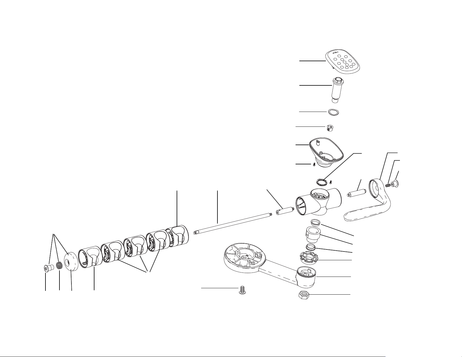
Figure 50. Holder Assembly
7
1
2
3
4
5
6
8
9
10
11
12
13
12
14
15
16
17
22 21
20
19
18
19
24 8
23
Delivery System
86.0016.00 Rev A 51
Page 60
A-dec 200 Service Guide
1
2
3
4
7
6
5
8
10
11
12
9
13
Control Block Assembly
Item Part Number Description Item Part Number Description
1 38.0712.00 Water coolant stem (with O-ring) 7 38.0713.00 Air coolant stem (with O-ring)
2 38.0710.00 † Block cap 8 021.016.01 Plug, package of 10
3 38.0711.01 Diaphragm, package of 5 9 004.005.02 Washer, package of 10
4 38.1839.00 Control block assembly (with barbs) 10 023.004.03 Barb, 1/8", package of 10
5 38.0766.02 Flow control screw, package of 5 11 38.1775.00 Performer (A-dec 200) block service kit
6 001.021.00 Screw 12 023.001.03 Barb, 1/4", package of 10
13 023.805.01 Barb, 5/16", package of 10
† Indicates that the individual part is not available for sale
Figure 51. Control Block Assembly
52 86.0016.00 Rev A
Page 61
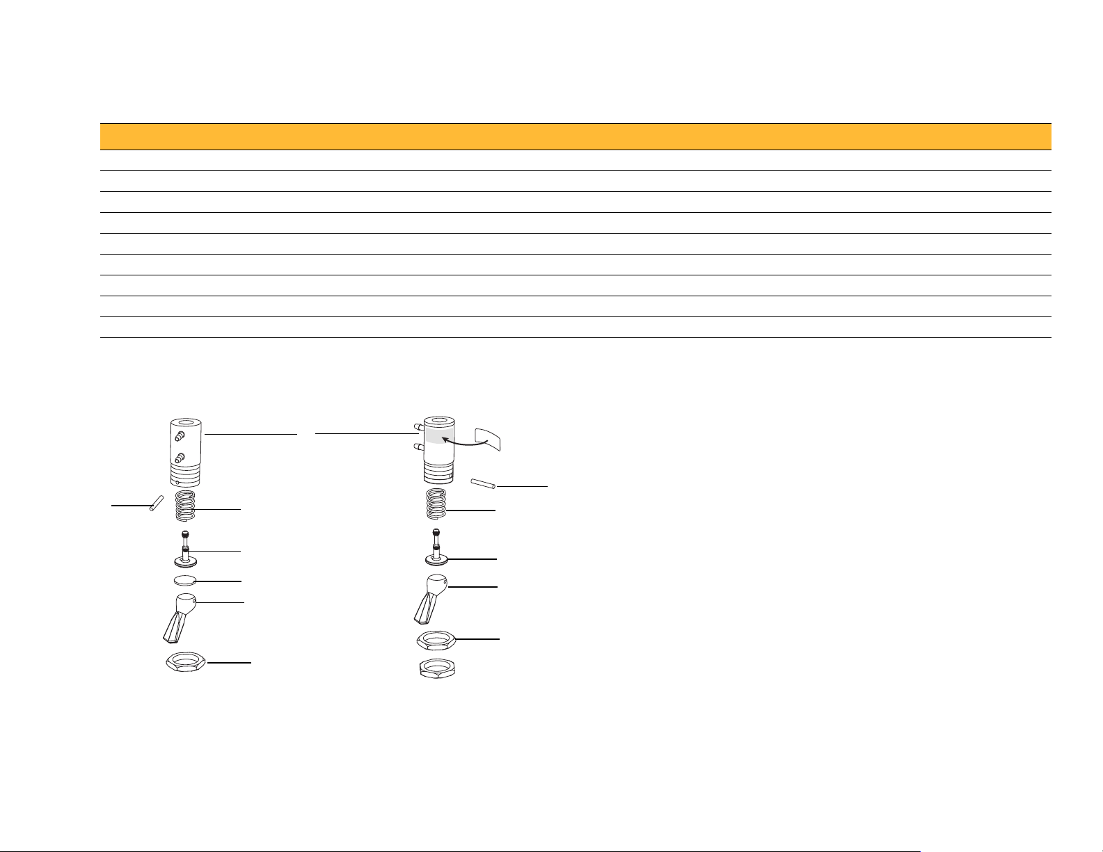
Toggles Assemblies (Flush Toggle and Master On/Off Toggle)
33.0009.83
(Flush Toggle)
33.0173.00
(Master On/Off Toggle)
2
3
4
5
6
7
1
1
3
8
9
7
Item Part Number Description
1 011.038.01 Pin, , package of 10
2 33.0050.00 Valve Body
3 22.0040.00 Spring
4 29.0830.00 Stem With O-rings, 2 Way
5 33.0007.00 Disk
6 33.0036.01 Toggle, Momentary, Gray
7 006.009.00 Hex Nut, 15-32 X 9/16 X 3/32
8 29.0840.00 Stem With O-rings, 3 Way
9 22.0462.03 Toggle, Gray 3
Figure 52. Flush Toggle and Master On/Off Toggle
Delivery System
86.0016.00 Rev A 53
Page 62

A-dec 200 Service Guide
1
2
3
Oil Collector
Item Part Number Description
1 001.016.01 Socket head screw, 10-32 X 3/8"
2 026.143.0 Gauze pad
3 77.0059.01 Oil collector assembly, white 2
Figure 53. Oil Collector
54 86.0016.00 Rev A
Page 63

CUSPIDOR AND SUPPORT CENTER
5
This section provides detailed information related to service, maintenance,
and adjustment of the A-dec 200 cuspidor and support center.
Contents
• Product Overview, page 55
• Service, Maintenance, and Adjustments, page 56
• Illustrated Parts Breakdown, page 57
Product Overview
A-dec 200 Support Center provides chair side mounting of the A-dec 200
Delivery System, Cuspidor, A-dec 200 Dental Light, and Assistant’s
Instrumentation. The support center mounts to the A-dec 200 chair using a
post mount.
Figure 54. A-dec 200 Support Center with Cuspidor
86.0016.00 Rev A 55
Page 64
A-dec 200 Service Guide
Pinch Valve
Service, Maintenance, and Adjustments
Bowl Rinse Flow Adjustment
Adjustments to the cuspidor bowl rinse flow are made inside the support
center. To adjust the flow:
1. Loosen the two thumb screws at the bottom of the support center and
carefully pull the cover out.
2. With the cuspidor bowl rinse on, tighten or loosen the pinch valve to
adjust the flow.
3. For the best rinsing action, adjust the flow pattern by rotating the bowl
rinse.
Figure 55. Pinch Valve Adjustment
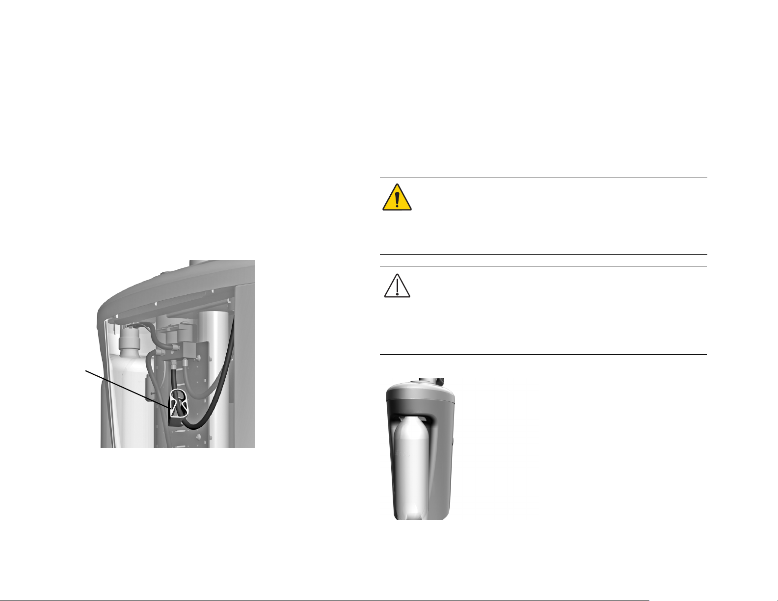
Self-Contained Water System
The self-contained water system provides water to the handpieces,
syringes, and cuspidor cupfill. The system includes a 2 liter water bottle
that mounts to the support center and offers a way to ensure the quality of
treatment water. Turn the bottle counterclockwise to remove it.
WARNING Use only A-dec self-contained water bottles. Do not use
any other bottles, including glass or plastic beverage bottles. Do
not use damaged bottles. These can pose a serious safety hazard
while pressurized. A-dec plastic water bottles cannot withstand
heat sterilization. Attempting to do so will damage the bottle and
your sterilizer.
CAUTION Use caution when using the self-contained water
system with accessories that require and uninterrupted water
supply (such as scalers) as these could get damaged without a
continuous water source. Do not use saline solutions, mouth
rinses, or any chemical solutions (not specified in this guide) in
your A-dec self-contained water system. These may damage the
system components and cause your dental unit to fail.
Figure 56. Self-Contained Water Bottle
Adjusting the Cuspidor Cupfill and Bowl Rinse
For adjustment information, see "Cuspidor Cupfill and Bowl Rinse" on
page 34.
56 86.0016.00 Rev A
Page 65

Illustrated Parts Breakdown
Cuspidor
This section contains illustrated parts breakdowns specific to the A-dec 200
Support Center and Cuspidor.
Part Identification
In this section, you will find serviceable components tables that correspond
to the illustrations. The tables identify all parts and kits, including those
that are not for sale. Parts that are not for sale are indicated with the symbol
shown below:
†— Indicates that the individual part is not available for sale. These parts
are typically part of a kit and/or larger assembly that is for sale.
Contents
• A-dec 200 Support Center, page 58
• A-dec 200 Cuspidor, page 60
• Self-Contained Water Bottle, page 61
• Cupfill/Bowl Rinse Manifold, page 62
86.0016.00 Rev A 57
Page 66

A-dec 200 Service Guide
A-dec 200 Support Center
Item Part Number Description
1 — Cuspidor assembly, (see page 60)
2 75.2271.00 Cuspidor bushing
3 75.2252.00 Top cover, white 2
4 044.184.00 Limit switch
5 001.218.00 Screw
6 — Assistant’s telescoping arm assembly (see page 68)
7 005.002.00 Screw
8 60.0080.00 Mounting plate
9 003.112.00 Top cover mounting screws
10 75.2259.00 Top plate
11 75.2253.00 Side cover, white 2
12 75.2254.00 Front cover, white 2
13 38.1803.00 Cupfill/bowl rinse manifold (see page 62)
14 75.2270.00 Chassis
15 027.064.00 Thumbscrew
16 75.2258.00 Support chassis
17 24.0388.02 Regulator assembly, 40 PSI preset
18 90.1167.00 Data line PCB
19 90.1082.00 Stand off, package of 5
20 77.1086.00 Lower bushing
21 75.0150.00 Post plug
22 14.0486.00 Water bottle assembly (see page page 61)
23 006.052.00 Nut
24 77.1085.00 Upper bushing
25 77.1087.00 Trim ring
26 75.2255.00 Rear cover, white 2
58 86.0016.00 Rev A
Page 67
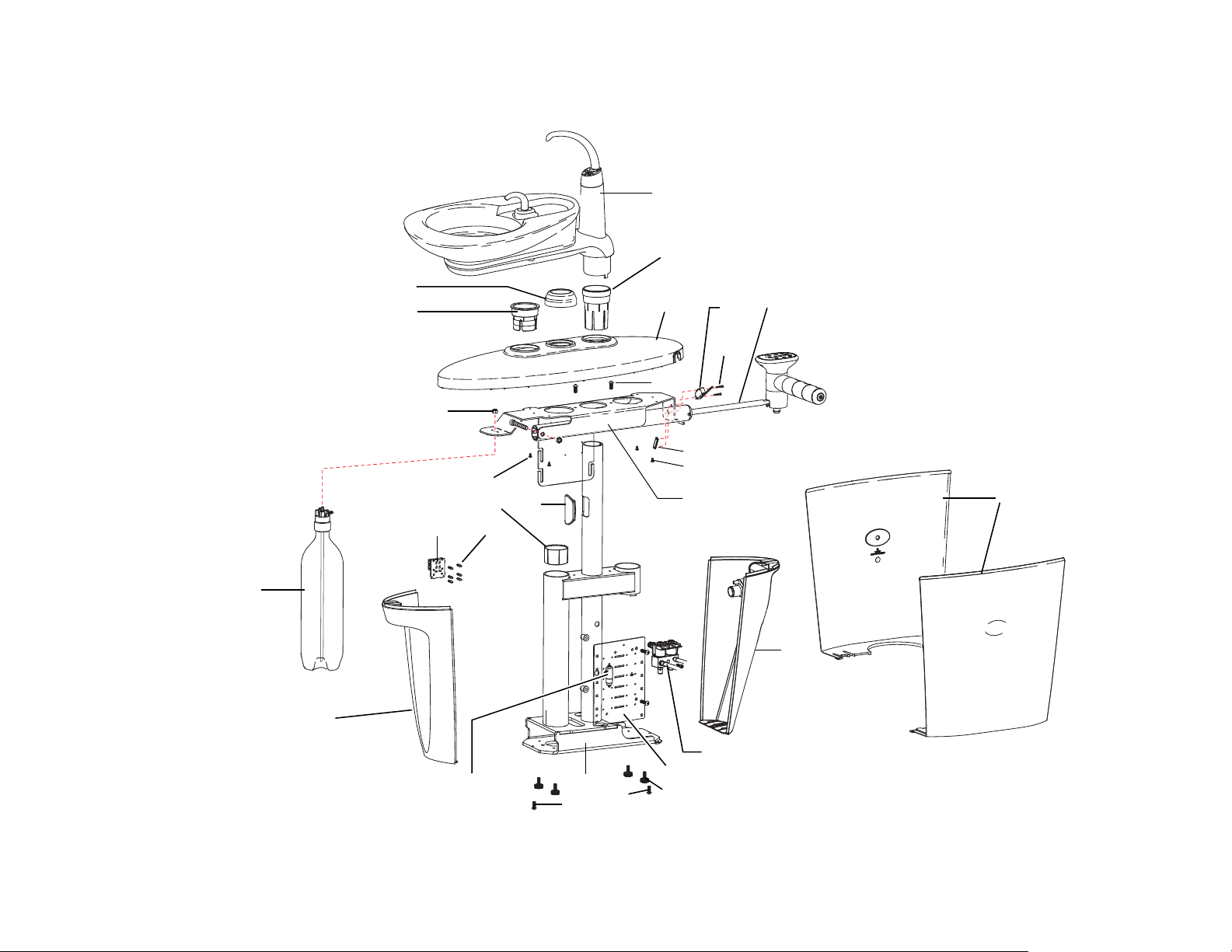
Figure 57. A-dec 200 Support Center
1
Cuspidor Assembly (see page 60)
2
3
6
Assistant’s Telescoping Arm
(see page 68)
4
5
7
24
22
Self-Contained Water
Bottle Assembly,
(see page 61)
9
25
19
11
13
Cup Fill/Bowl Rinse Manifold
(see page 62)
15
7
14
17
12
23
8
18
20
21
9
10
16
7
26
Cuspidor
86.0016.00 Rev A 59
Page 68

1
2
3
4
5
6
7
8
9
10
11
13
22
24
21
14
15
23
16
17
18
12
29
17
19
20
25
26
27
28
A-dec 200 Service Guide
A-dec 200 Cuspidor
Item Part Number Description
1 77.0042.01 Spout, bowl rinse, back mount
2 77.1112.00 Spout, cupfill, cuspidor
3 030.011.02 O-ring, AS568-011, .301 ID x .070 W, package of 10
4 77.0105.00 Socket, bowl rinse spout
5 030.014.02 O-ring, AS568-014, .489 ID x .070 W, package of 10
6 030.012.02 O-ring, AS568-012, .364 ID x .070 W, package of 10
7 77.0044.01 Gasket, spout, cup cuspidor
8 77.0099.00 Button, cuspidor fill/rinse, left
9 77.0100.00 Button, cuspidor fill/rinse, right
10 43.0010.00 Switch assembly, 20"
11 77.0097.01 Support, cuspidor mount with barbs
12 005.088.00 Screw, socket head, 6-32 x 1-1/4
13 001.088.00 Screw, socket head, 10-32 x 5/8 Stainless Steel
14 77.0108.01 Top housing, cuspidor, back mount
15 77.0040.00 Tube, drain, cuspidor, back mount
16 035.053.01 O-ring, vacuum, 20 mm x 2 mm, package of 10
17 002.058.00 Screw, button head socket, 3/8-16 x 3/4
18 004.141.00 Washer, flat, STL, .261 ID
19 77.0109.01 Bottom housing, cuspidor, back mount
20 75.2273.00 Hub, cuspidor
21 75.2274.00 Cuspidor stop
22 005.106.00 Screw, 10-32 x 2 1/2, socket head
23 12.0991.00 Drain seal
24 001.088.00 Screw, socket head, 10x32 x 5/8 stainless steel
25 77.0236.00 Bracket, hold down, cuspidor
26 006.009.00 Nut, hex, 15/32-32 x 9/16 x 3/32
27 004.132.00 Washer, flat, stainless steel, .500 ID
28 004.035.00 Washer, flat, nylatron, .511 ID
29 77.0038.01 Bowl, cuspidor, ceramic
Figure 58. Cuspidor
60 86.0016.00 Rev A
Page 69

Self-Contained Water Bottle
1
2
Item Part Number Description
1 14.0487.00 200 self-contained cap assembly
2 14.0486.00 Water bottle
Cuspidor
Figure 59. Self-Contained Water Bottle
86.0016.00 Rev A 61
Page 70

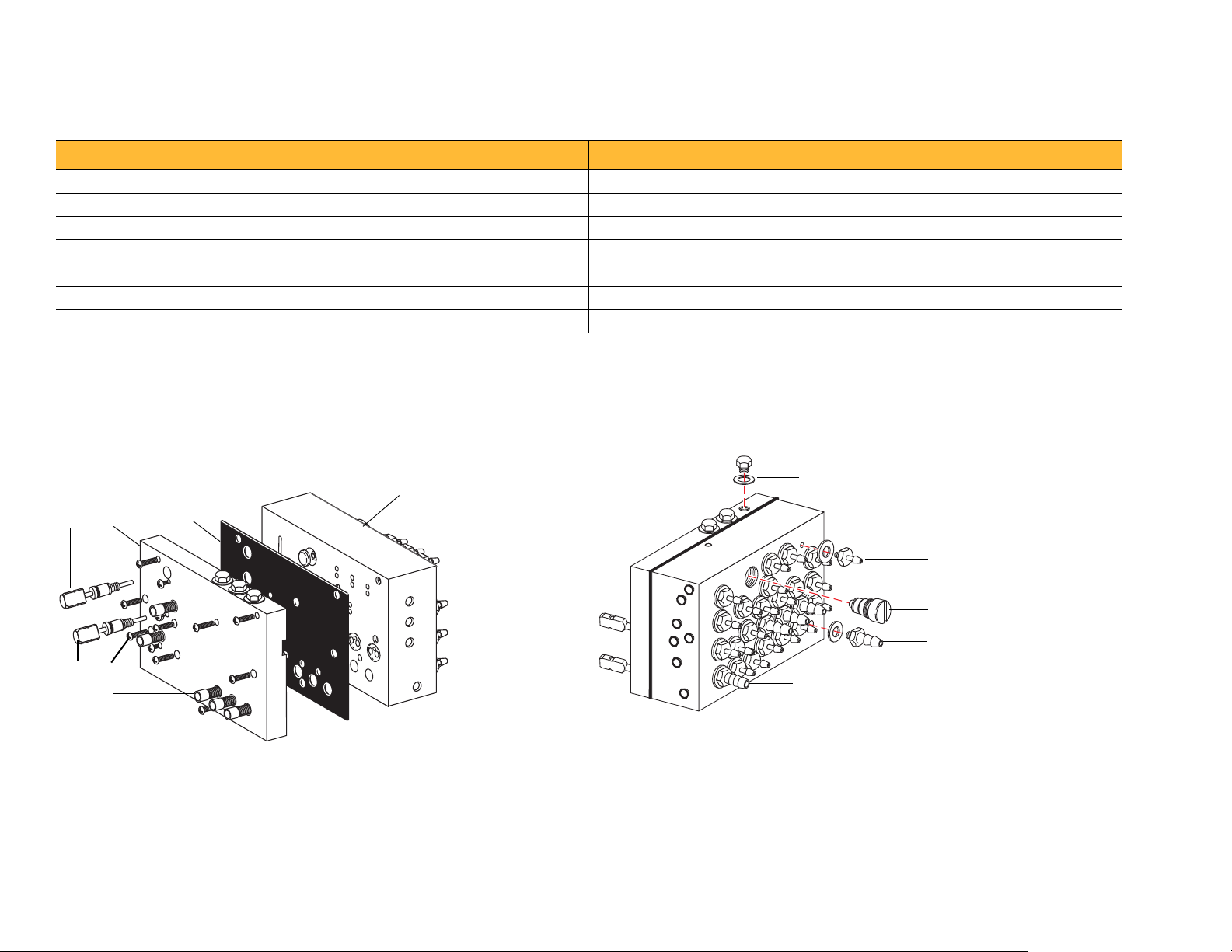
A-dec 200 Service Guide
2
3
5
6
7
5
7
4
6
1
Cupfill/Bowl Rinse Manifold
Item Part Number Description
1 041.660.00 Solenoid, 24 vac assembly
2 030.016.02 O-ring, package of 10
3 77.0816.00 † Manifold
4 001.088.00 Socket head screw, 1/4 - 20 x 5/8, stainless steel
5 004.005.02 Washer, package of 10
6 023.805.01 Barb, 5/16 x 10 - 32, package of 10
7 023.804.00 Barb, 5/16 x 1/8 NPT
† Indicates that the individual part is not available for sale
Figure 60. Cupfill/Bowl Rinse Manifold
62 86.0016.00 Rev A
Page 71
ASSISTANT’S INSTRUMENTATION
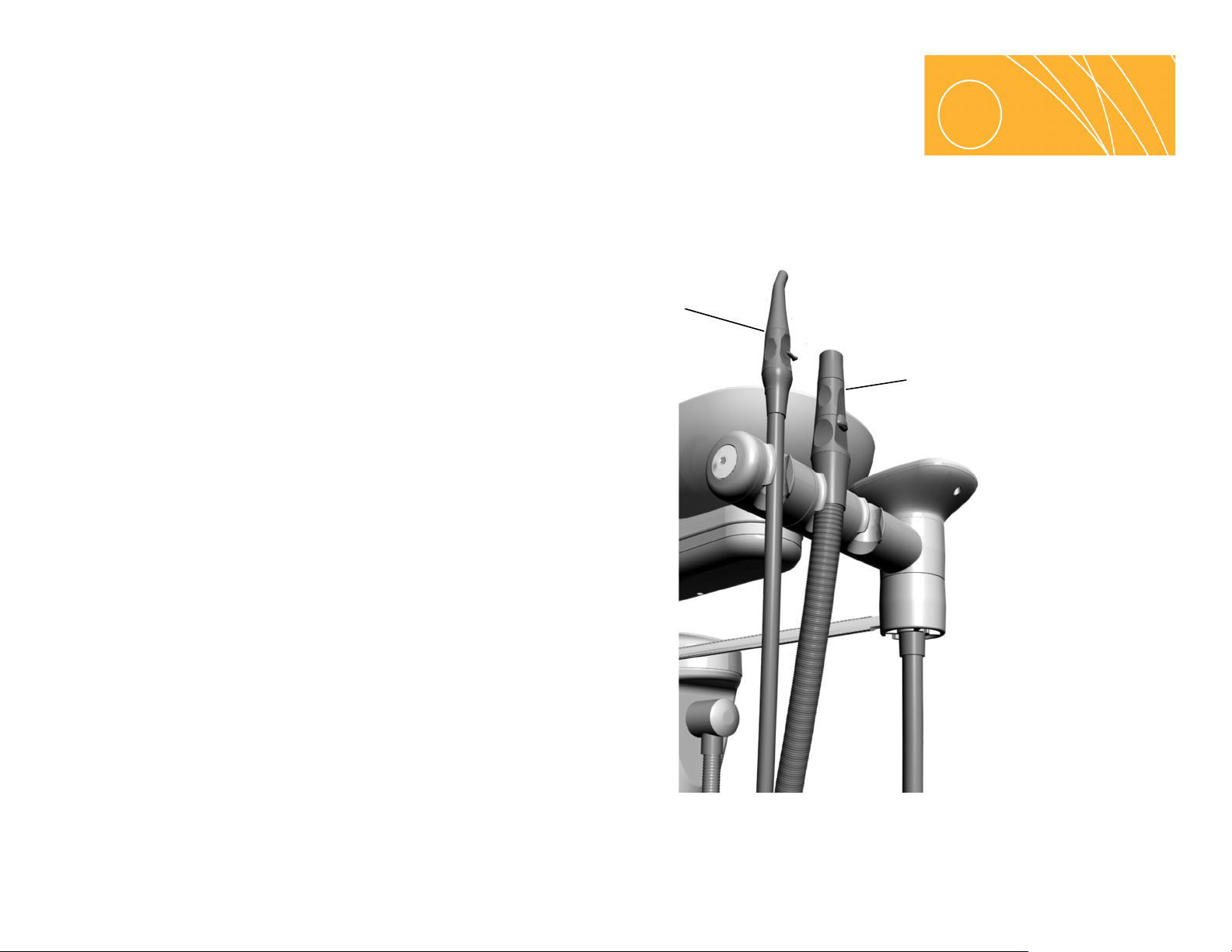
HVE
SE
6
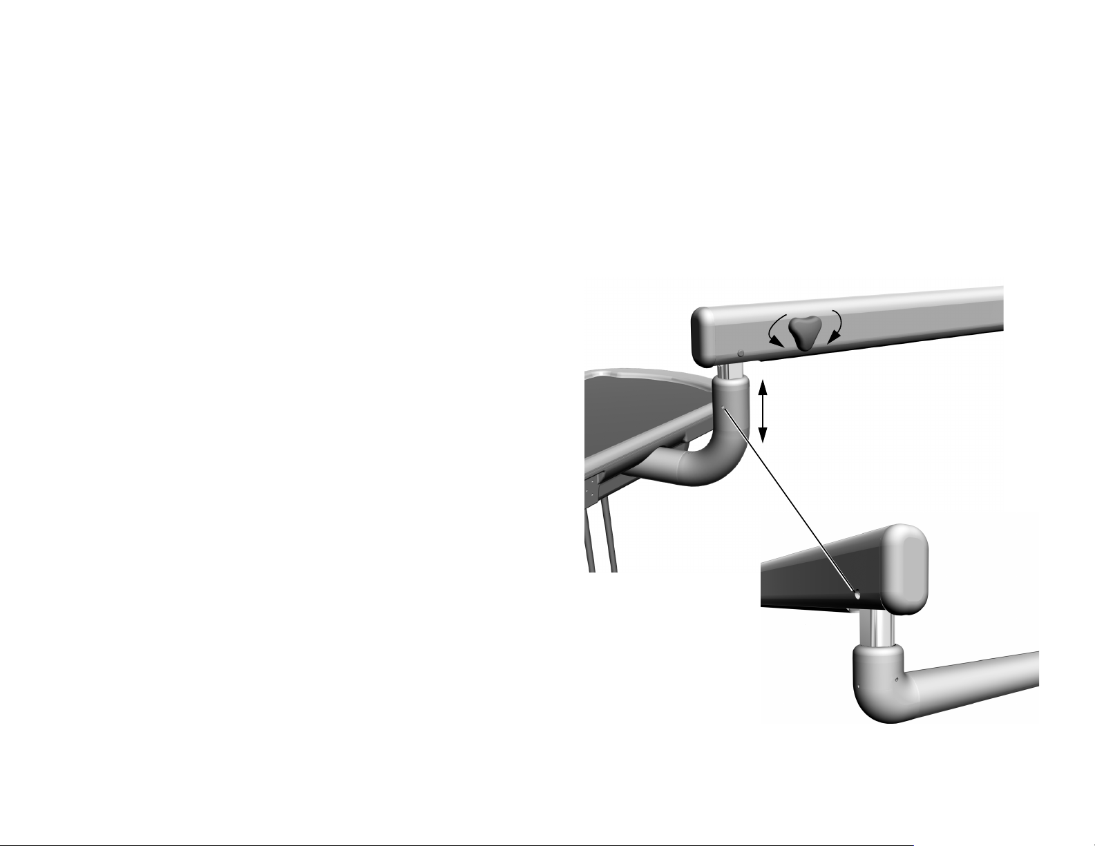
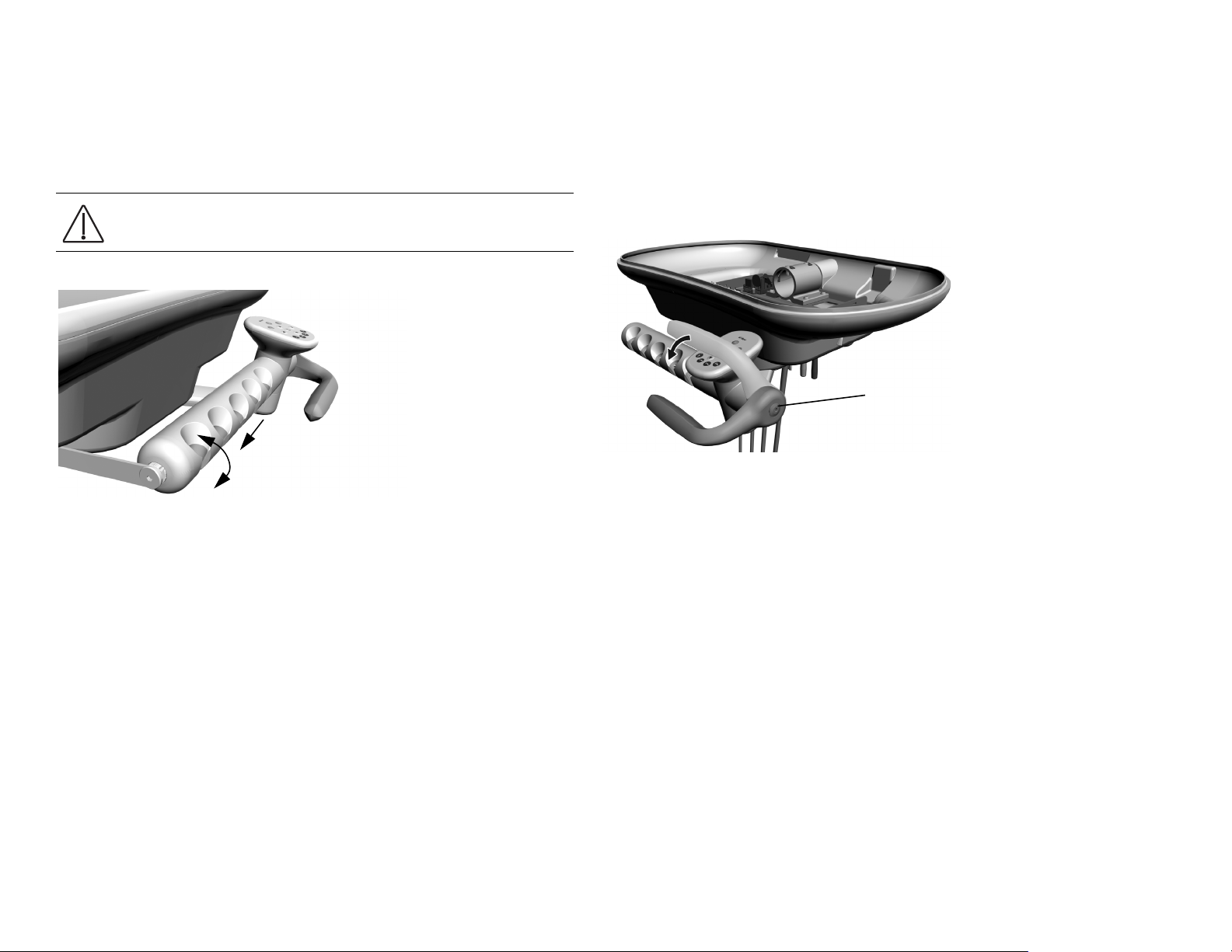
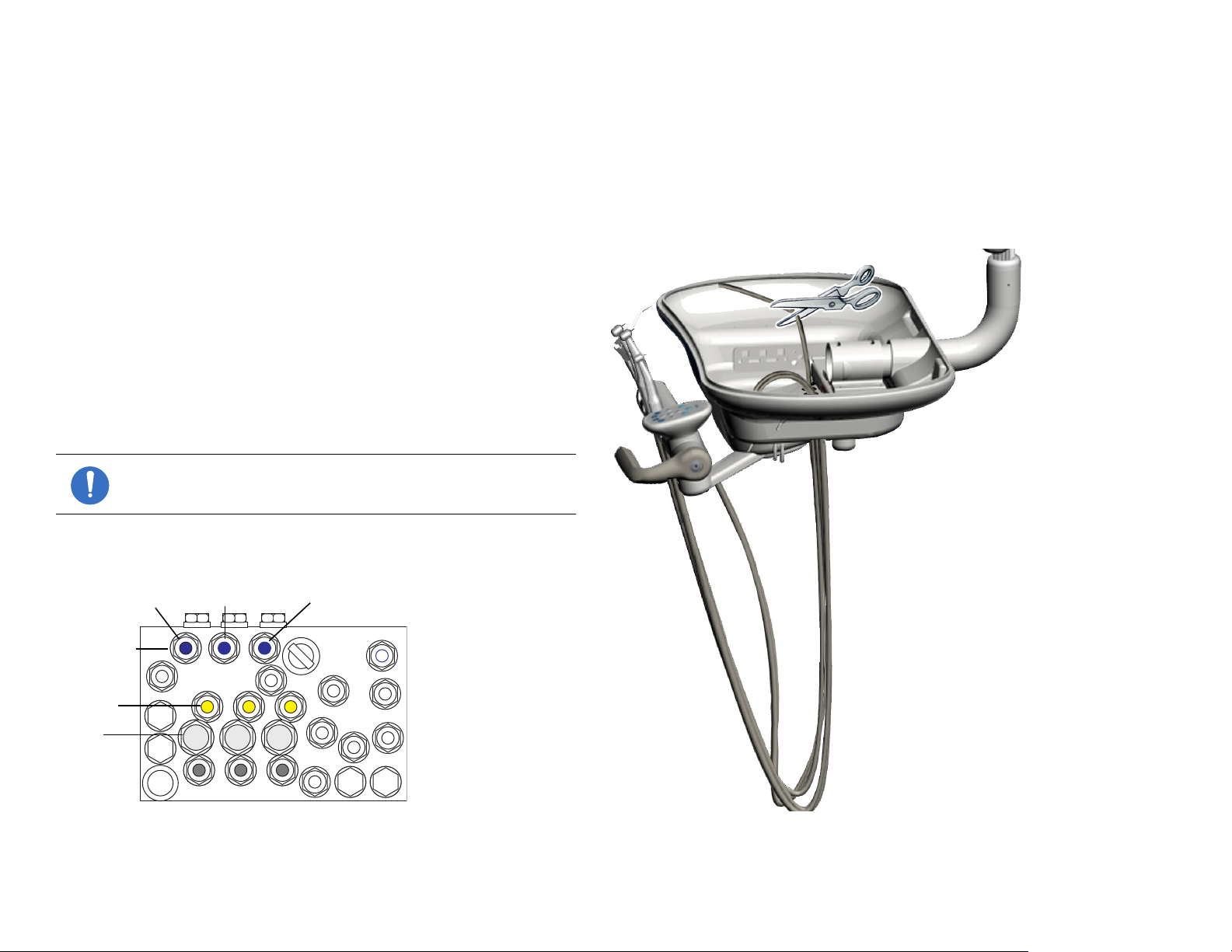
This section provides detailed information related to service, maintenance,
and adjustment of the A-dec assistant’s instrumentation.
Contents
• Product Overview, page 63
• Service, Maintenance, and Adjustments, page 64
• Illustrated Parts Breakdown, page 67
Product Overview
The A-dec 200 assistant’s instrumentation is equipped with an autoclavable
syringe, high volume evacuator (HVE), and saliva ejector (SE). Some
configurations may include an optional dual HVE or instrumentation that
supports a chair-side or single-operatory vacuum system. Integrated into
the support center is the solids collector, which connects with the HVE and
SE to separate solids from the evacuated material.
The assistant’s vacuum instruments disconnect from the tubing for easy
cleaning, and they are fully autoclavable.
Figure 61. Assistant’s Instrumentation
86.0016.00 Rev A 63
Page 72

A-dec 200 Service Guide
Service, Maintenance, and Adjustments
Auto-air Holder
Each handpiece in the holder assembly automatically activates when you
lift it from its holder.
Holders provide vacuum On/Off switching for users whose vacuum
system requires this functionality. The vacuum pump activates
automatically when you lift the HVE or SE from the holder. The vacuum
turns off when you place the HVE or SE back into the holder.
Figure 62. Auto-Air Holder
Positioning Assistant’s Holder
The independently adjustable holders rotate to allow customized
positioning for each instrument on the assembly.
To rotate holder:
1. Pull holder slightly away from the adjacent one.
2. Rotate to the desired position and release.
Figure 63. Rotating Instrument Holders
NOTE Auto-air holders rotate together. Standard holders rotate
individually
64 86.0016.00 Rev A
Page 73

Assistant’s Touchpad Connections
24 VAC
Data Line
The assistant’s instrumentation uses a standard touchpad that serves as a
single touch surface for controlling the chair, dental light, and cuspidor.
The touchpad can rotate 340° for access and visibility.
Figure 64. Assistant’s Touchpad with Standard Holder Connections
Vacuum Instrumentation
To use the HVE and SE, lift the holder from the valve to activate the
vacuum.
NOTE Lifting the handpiece from the holder only activates the
vacuum with auto-air switches.
Figure 65. HVE and SE Operation
86.0016.00 Rev A 65
Page 74

A-dec 200 Service Guide
Solids Collector
The solids collector aids in preventing solids from entering the central
vacuum system.
CAUTION Use appropriate gloves when handling
contaminated parts.
Replace Solids Collector Screen
1. Turn off vacuum or open the HVE control valve.
2. Remove the solids collector cap.
3. Remove the solids collector screen.
4. Discard the screen according to your local regulations.
CAUTION Do not empty the screen into the cuspidor. Doing so
could plug the drain.
5. Insert the new screen in the collector and replace the cap.
CAUTION Ensure that the solids collector cap is inserted properly.
Failure to do so will not allow for proper suction.
Figure 66. Replace Solids Collector Screen
66 86.0016.00 Rev A
Page 75

Illustrated Parts Breakdown
This section contains illustrated parts breakdowns specific to the A-dec 200
Support Center and Cuspidor.
Part Identification
In this section, you will find serviceable components tables that correspond
to the illustrations. The tables identify all parts and kits, including those
that are not for sale. Parts that are not for sale are indicated with the symbol
shown below:
†— Indicates that the individual part is not available for sale. These parts
are typically part of a kit and/or larger assembly that is for sale.
Contents
• Telescoping Assistant’s Arm, page 68
• Assistant’s Touchpad Assembly, page 69
• Assistant’s Auto-Air Holder, page 70
• Assistant’s Standard Holder, page 72
86.0016.00 Rev A 67
Page 76
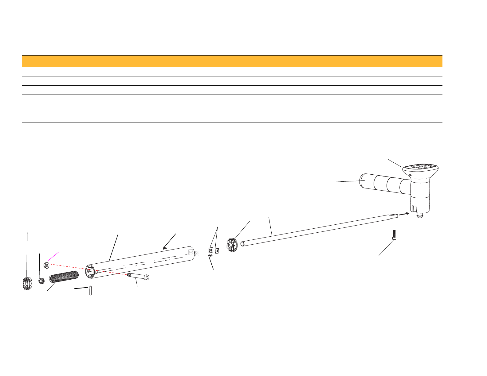
A-dec 200 Service Guide
Assistance Touchpad Assembly
(see page 69)
1
2
3
4
4
8
5
6
7
11
Holders Assembly
(see page 70 for Auto-Air;
page 72 for Standard)
9
10
12
Telescoping Assistant’s Arm
Item Part Number Description Item Part Number Description
1 75.0018.00 Assistant’s arm slide 7 77.1082.00 Assistant’s arm rod
2 018.005.00 Grommet, 1/4 ID x .38 groove 8 002.080.01 Socket head screw, 1/4-20 x 3/4
3 77.1081.00 Telescoping arm housing 9 001.134.00 Socket shoulder screw, 5/16-18 x 3/8 x 2
4 001.167.00 Button head socket screw, 6-32 x 3/8, stainless steel 10 011.099.00 Pin dowel, .187 dia x 1.00 lg
5 006.040.00 Retainer nut, 6-32 11 006.132.00 † Nut, lock, 5/16-18 x 1/2 x .275
6 75.0019.01 End cap 12 024.152.01 Convolute tubing, 5/8 ID - 4" long
† Indicates that the individual part is not available for sale
Figure 67. Telescoping Assistant’s Arm
68 86.0016.00 Rev A
Page 77

Assistant’s Touchpad Assembly
1
2
3
4
5
6
7
8
6
Item Part Number Description
1 90.1186.00 Touchpad cap
2 77.0123.00 Pass-through bolt
3 99.0651.00 Spline
4 77.0335.01 Touchpad base
5 003.078.00 Socket head screw, 4-40 X 1/4
6 004.173.00 Washer
7 004.237.00 Wave spring washer
8 004.060.00 Washer
Figure 68. Assistant’s Touchpad Assembly
86.0016.00 Rev A 69
Page 78

A-dec 200 Service Guide
Assistant’s Auto-Air Holder
Item Part Number Description Item Part Number Description
1 — * Nut 13 99.1142.00 † SE/Syringe Holder
2 013.011.00 Spring 14 83.0624.00 † Axle
3 90.1216.00 End-Cap Assembly 15 83.0585.00 † Special Nut, 4-40 X .75
4 006.011.00 Nut, 4-40 X 1/4 X 3/32 16 83.0648.00 Holder Base Axle
5 83.0573.00 † Holder Rod † 17 — Touchpad Assembly
6 99.1141.00 † 15 mm HVE Holder † 18 99.0698.00 Bearing
7 83.0583.00 † Sensor Spring † 19 77.0956.01 Turret Adaptor
8 001.021.00 Socket Head Screw, 4-40 X 1/2 Stainless Steel 20 023.822.00 5/8" Barb
9 010.019.00 E-ring, .904 ID 21 99.0687.00 Sleeve
10 83.0582.00 † Sensor Spool 22 77.0385.00 Stop
11 83.0581.00 † Sensor Button 23 83.0647.00 † Inner Hub
12 99.1143.00 † Auto-Air Holder
† Indicates that the individual part is not available for sale
* Part of Item 3, p/n 90.1216.00
70 86.0016.00 Rev A
Page 79

Figure 69. Auto-Air Assistant’s Holders Assembly
1
2
10
6
7
8
9
12
14
15
17
18
18
21
19
23
3
4
5
11
16
22
20
13
86.0016.00 Rev A 71
Page 80

A-dec 200 Service Guide
1
2
3
5
4
6
7
6
Assistant’s Standard Holder
Item Part Numbers Description
1 99.0649.01 † Tu r r et
2 99.0701.00 Turret axle, assistant’s arm
3 99.0653.03
99.0650.03
99.0652.03
4 99.0660.00 † Axle
5 99.3684.00 End cap assembly kit
6 99.0698.00 Bearing
7 99.0699.00 Inner hub assistant’s arm
† Indicates that the individual part is not available for sale
Figure 70. Assistant’s Standard Holder Components
Holder, SE/Syringe kit, White 2, 9 mm
Holder, standard HVE kit, White 2, 11 mm
Holder, assistant’s HVE kit, White 2, 15 mm
72 86.0016.00 Rev A
Page 81

UTILITIES
7
This section provides detailed information related to service, maintenance,
and adjustment of the A-dec 200 utility area.
Contents
• Product Overview, page 74
• Service, Maintenance, and Adjustments, page 75
• Illustrated Parts Breakdown, page 77
Figure 71. Utilities on A-dec 200 Dental Chair
86.0016.00 Rev A 73
Page 82

A-dec 200 Service Guide
Front Post
Back Post
Manual Shutoff
Valv es
Floor Box Cover
NOTE If cable ties are present in
the product and you need to
remove them for servicing, make
sure to replace the ties after service
is completed.
1
2
3
4
5
6
7
8
9
10
11
12
Product Overview
The utilities for your system are located under the chair floor box. To access
the utilities, pull the floor box cover up at the front posts, and then forward
and up to slide the cover off the back posts.
Shutoff Valves
Manual shutoff valves control the air and water to the system. To prevent
leaks, these valves should remain fully open (turned counterclockwise)
except while servicing the system.
Air and water pass through separate filters before entering the regulators.
Replace these filters when they become clogged and cause restricted flow.
Figure 72. Floorbox Cover Removal and Shutoff Valves
Gauge and Pre-Regulator
The pre-regulator controls the air and water pressure in the unit. The gauge
displays the unit air pressure.
Figure 73. Utilities Diagram
Table 9. Utilities Descriptions
Item Description Item Description
1 Moisture separator
(optional)
2 Cuspidor drain tube 8 5/8" exhaust tube
3 20 mm tube to drain 9 Durr adapter
4 Connector clips (four) 10 20 mm tube to liquid
5 Liquid separator tank 11 Y connector
6 Cap 12 Exhaust tube
7 Air exhaust
separator drain
74 86.0016.00 Rev A
Page 83

Service, Maintenance, and Adjustments
Filter Housing
Filter
Manual Shut
Off Valve
O-ring
Beveled Edge
Manual Air
Shutoff Valve
Filter Housing
Filter
Filter Housing
Manual Water
Shutoff Valve
Utilities
Air and Water Filter Replacement
Air and water pass through separate filters before entering the regulators.
Replace a filter when it becomes clogged and causes restricted flow.
Figure 74. Air and Water the Filter Components
.
CAUTION To ensure proper delivery system operation,
install the filter with the beveled edge facing the manifold.
NOTE Turn the pre-regulator knob clockwise to increase
pressure and counterclockwise to decrease pressure. Read
the pressure gauge while adjusting. Water pressure will
increase/decrease by half of the gauge indication.
Figure 75. Replacing Filters
To replace the Filter:
1. Turn off the master toggle and close the manual shutoff valves (turn
clockwise).
2. Bleed the system of air and water pressure by operating the syringe
buttons until air and water no longer flow.
3. Using a standard screwdriver, remove the filter housing from the air or
water filter pre-regulator assembly and remove the filter.
4. Replace the filter if it is clogged or discolored. Install the filter with the
beveled edge facing the manifold.
86.0016.00 Rev A 75
Page 84

A-dec 200 Service Guide
76 86.0016.00 Rev A
Page 85

Illustrated Parts Breakdown
Utilities
This section contains illustrated parts breakdowns specific to the A-dec 200
utilities.
Part Identification
In this section, you will find serviceable components tables that correspond
to the illustrations. The tables identify all parts and kits, including those
that are not for sale. Parts that are not for sale are indicated with the symbol
shown below:
†— Indicates that the individual part is not available for sale. These parts
are typically part of a kit and/or larger assembly that is for sale.
Contents
• Air Filter/Regulator Assembly, page 78
• Water Filter/Regulator Body Assembly, page 79
86.0016.00 Rev A 77
Page 86

A-dec 200 Service Guide
13
1
12
7
6
11
3
5
4
8
9
10
2
14
15
16
17
18
19
20
21
Air Filter/Regulator Assembly
Item Part Number Description Item Part Number Description
1 026.154.00 Gauge 11 24.0135.00 Regulator, body, white
2 001.024.00 Screw 12 22.0460.00 Spring
3 24.0365.00 Bracket 13 24.0132.00 Piston with O-ring
4 24.0232.00 Stud, filter/regulator manifold 14 22.0440.02 Diaphragm, package of 10
5 24.0234.01 Filter, package of 6 15 24.0368.00 Valve cover
6 030.019.03 O-ring, package of 10 16 004.005.02 Washer, flat nylon, 187 ID
7 24.0229.00 Filter housing 17 023.004.01 Barb, 1/8 x 10-32
8 021.042.00 Adaptor 18 001.026.00 Screw, socket head, 6-32 x 7/8"
9 24.0162.00 Manifold, filter/regulator 19 006.015.00 Nut, hex, 6-32 x 5/16 x 9/64"
10 24.0137.01 Gasket, 9-hole 20 24.0182.81 Regulator, air assembly
21 006.009.00 Nut, hex, 15/32 - 32 x 9/16 x 3/32"
Figure 76. Air and Water Filter/Regulators Body Assembly Components
78 86.0016.00 Rev A
Page 87

Water Filter/Regulator Body Assembly
1
2
3
4
5
6
17
7
8
9
10
11
16
12
15
14
13
18
19
Item Part Number Description
1 24.0229.00 Housing, filter
2 030.019.03 O-ring, package of 3
3 24.0234.02 Filter kit, package of 2
4 24.0232.00 Stud, filter/regulator manifold
5 021.016.04 Plug, hex head, 10 - 32
6 004.005.02 Washer
7 021.042.00 Adapter, 1/8" MPT to 3/8"
8 24.0137.01 9-hole gasket
9 24.0355.00 Body, black
10 013.032.00 Spring
11 24.0132.00 Piston with o-ring
12 24.0140.00 Spacer, water regulator
13 22.0440.02 Diaphragm, package of 10
14 023.004.01 Barb, 1/8" x 10-32
15 004.005.01 Washer, flat nylon 187 ID
16 24.0368.00 Valve cover
17 001.021.00 Screw, socket head, 4-40 x 1/2", stainless steel
18 001.024.00 Screw, socket head, 4-40 x 3/8", stainless steel
19 24.0142.00 Plunger
Utilities
Figure 77. Air and Water Filter/Regulators Body Assembly Components
86.0016.00 Rev A 79
Page 88

A-dec 200 Service Guide
80 86.0016.00 Rev A
Page 89

DENTAL LIGHT
Light Shield
Ta b ( h id de n)
Light Shield
Pivot Housing/Diagonal
Tension Adjustment
8
This section provides detailed information related to service, maintenance,
and adjustment of the A-dec 200 Dental Light.
Contents
• Product Overview, page 82
• Service, Maintenance, and Adjustments, page 83
• Illustrated Parts Breakdown, page 89
Figure 78. A-dec 200 Dental Light
86.0016.00 Rev A 81
Page 90

A-dec 200 Service Guide
Treatment
Positions
X-Ray /Rinse PositionEntry/Exit Position
Product Overview
The dental light provides three intensities at the light head and the optional
touchpad.
Dental Light Specifications
• Electrical (Transformer Output): 12.1/16/17 VAC
• Bulb: Quartz Xenon Halogen, single-end prongs, extended life
• Rating: 17V/95 watts
• Color temperature: 4800 Kelvin
• Heat output: 325 BTU/Hour
• Light Pattern: 3.9" x 6.7" at 27.6" (100 mm x 170mm at 700 mm)
Nominal Light Intensity
• Composite: 4400 lux (743 fc)
• High: 17,000 lux (2230 fc)
On/Off Button
The dental light can be operated from the assistant’s or doctor touchpad.
To turn the light on, off, or change intensity, press the dental light button
on the touchpad.
Auto On/Off Feature
The optional auto on/off feature turns the light on when the chair back
reaches a treatment position. Press or , and the dental light turns off
Figure 79. Touchpad and Footswitch Light Features
To disable the auto. Press any button that moves the chair into an operating
position. The dental light turns on when the chair reaches that position.
To activate/deactivate the auto on/off feature, press and hold the program
and dental light buttons simultaneously for three seconds. One beep
confirms the auto on/off is off. Three beeps confirm the auto on/off is on.
82 86.0016.00 Rev A
Page 91

Service, Maintenance, and Adjustments
10
A
M
P
10
A
M
P
On
On
Off
LED
Indicator
Dental
Contents
• Dental Light Wire Connections on the 200 Dental Chair, page 84
• Intensity Switches, page 83
• Dental Light Wire Connections on the 200 Dental Chair, page 84
• Dental Light Relay Circuit Board, page 86
• Bulb Replacement, page 88
• Rotation Adjustments, page 87
• Bulb Replacement, page 88
Circuit Breaker Location
A circuit breaker will interrupt the flow of electricity under abnormal
conditions. If the circuit breaker should trip, inspect the wiring to ensure
there are no shorts, and reset by pushing the circuit breaker. The circuit
breaker for the dental light is located on the power supply.
Figure 80. Circuit Breaker
Intensity Switches
A-dec dental lights can be operated from the manual 3-way switch or the
optional touchpad. The dental light is always off when the 2-way switch is
in the center location. To turn the light on or off from the touchpad, press
and hold the dental light button.
The dental light features two intensities: high and composite (low). For
systems without a touchpad, flip the 3-way switch either side of center to
select the intensity. For systems with a touchpad, ensure that the 2-way
switch is in either of the On positions, and press the light button to choose
the intensity. When the light is in the composite setting, the LED indicator
on the touchpad flashes.
Figure 81. Intensity Switches
86.0016.00 Rev A 83
Page 92
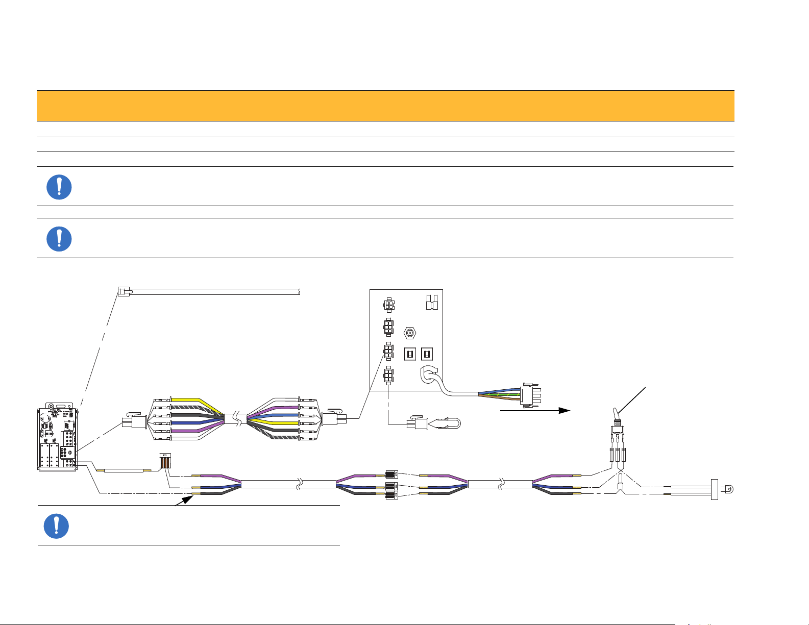
A-dec 200 Service Guide
Dental Light
Circuit Board
BLK/WHT
Blk
BLU
VIO
WHT
YEL WHT
VIO
BLU
YEL
BLK/WHT
Blk
VIO
BLU
Blk
VIO
BLU
Blk
VIO
BLU
Blk
VIO
WHT
WHT
Firststar Light
Switch
200 PS Power Cord
To AUX Power Connector
on Chair Circuit Board
300 W Power Supply
100 V (p/n 43.0214.00)
100 - 240 V (p/n 43.0215.00)
220 - 240 V (p/n 43.0216.00)
WHT
NOTE For field installation, cut off the existing red
connector and strip the wires.
BLU
Blk
Dental Light Wire Connections on the 200 Dental Chair
Term in al
Vol tag e Terminal Label Wire
200 Dental Light
J2 17/12.1 VAC VIO Violet
J2 0 VAC BLK Black
NOTE See "Circuit Board Components" on page 9 to identify dental light connections on the chair circuit board.
NOTE The LED indicator must be connected to the power supply for the dental light circuit board to function correctly.
Figure 82. Dental Light Wire Connections With Touchpad
84 86.0016.00 Rev A
Page 93

Figure 83. Dental Light Wire Connections Without Touchpad
Dental Light
Circuit Breaker
300 W Power Supply
100 V (p/n 43.0214.00)
100 - 240 V (p/n 43.0215.00)
220 - 240 V (p/n 43.0216.00)
200 PS Power Cord
To Auxiliary Power Connector on
Chair Circuit Board
Firstar Light Switch
Firstar Light Socket
WHT
WHT
VIO
BLU
BLU
BLU
BLU
BLK
BLK
BLK
BLK
VIO
VIO
VIO
Dental
86.0016.00 Rev A 85
Page 94
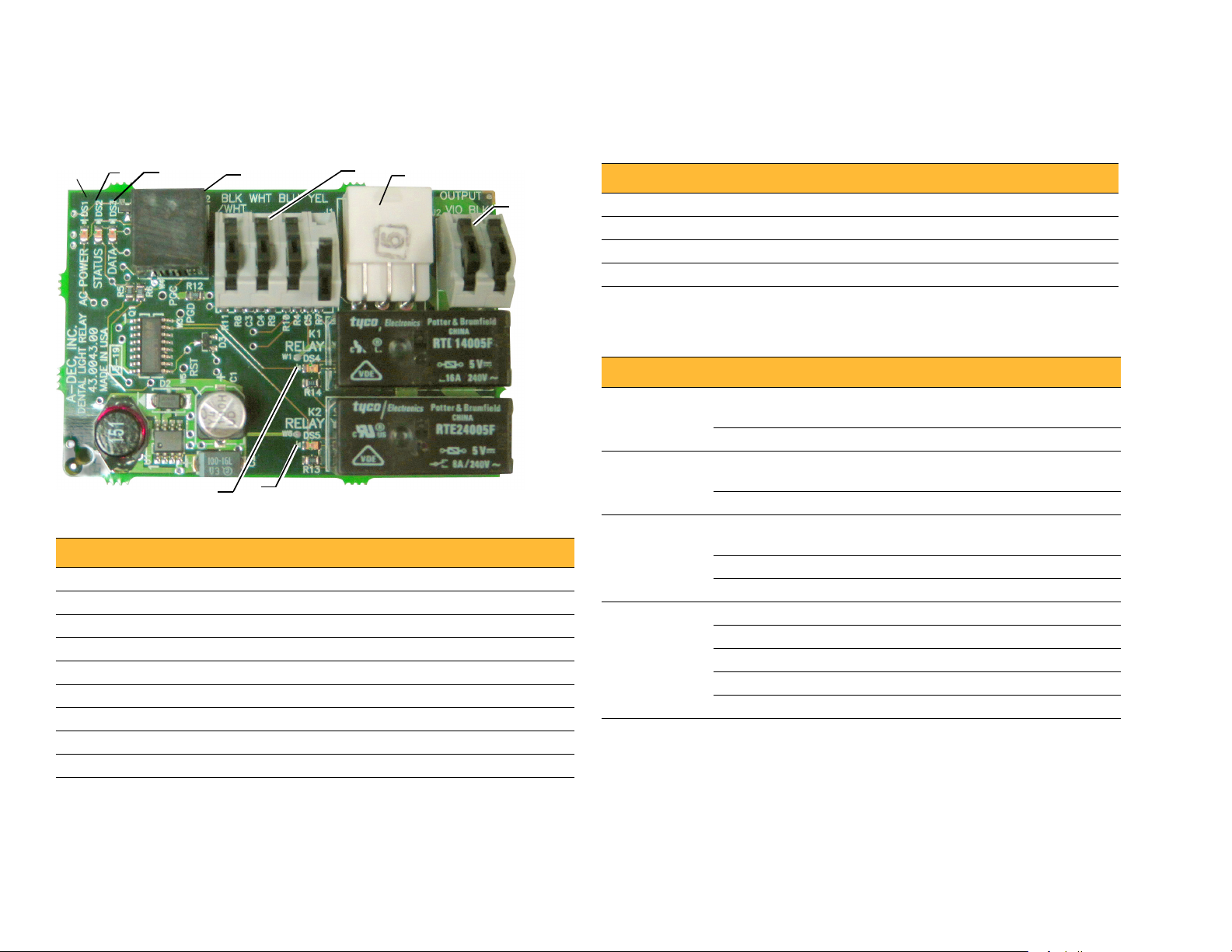
A-dec 200 Service Guide
6
8
9
7
3
2
4
5
9
4
5
1
Dental Light Relay Circuit Board
Figure 84. Dental Light Relay Circuit Board
Table 11. Dental Light Output Settings
Function K1 (DS4) K2 (D57) Output
Off Off Off 0 VAC
High intensity On Off 17 VAC
Composite intensity Off On 12 VAC
Medium Intensity On On 16 VAC
LED Identification
Table 12. LED Status and Descriptions
LED Status Description
DS1 - AC power
LED
DS2 - Status
LED
Table 10. Dental Light Relay Circuit Board Descriptions
Item Description
1DS1 - AC power LED
2 DS2 - Status LED
3DS3 - Data LED
4 DS4 - Dental Light relay LED
5 DS5 - Dental light relay LED
6 P1 - Input power
7P2 - Data port
8 J1 - Toggle switch inputs
9 J2 - Dental light output power
DS3 - Data LED Off No DCS communication, not connected to
DS4, DS5 Dental light
relay LEDs
Off No 24 VAC power, tripped circuit breaker,
power supply turned off, no line voltage
Green, steady 24 VAC at the terminal strip
Off System is not functioning, no power or
circuit board has failed
Green, steady Normal operation
the DCS, or DCS has failed
Green, steady Detects active DCS
Green, blinking Valid DCS message
DS4, DS5
Off, Off Dental light off
On, Off High intensity
Off, On Composite intensity
On, On Medium intensity
86 86.0016.00 Rev A
Page 95

Dental
Adjustment Nut
Loosen
Tighten
Tension Adjustment Screw
Tension Adjustment Nut
Yo k e P l u g
Flexarm Adjustments
Remove the screw and cover from the flexarm. Turn the tension adjustment
nut inside the flexarm using a 1/2" open end wrench. Tighten the nut by
turning it clockwise, if the flexarm moves too easily, or tends to drift down
by itself. Loosen the nut by turning it counterclockwise, if the arm drifts up.
NOTE The weight of the flex arm cover affects the flex arm
counter-balance. Set cover on flex arm to test tension adjustment.
Figure 85. Adjustment
Rotation Adjustments
If the light head is difficult to position, moves too easily, or tends to slip out
of position, the rotation tension can be adjusted diagonally and vertically.
Diagonal Adjustment
Use a 5/64" hex key to adjust the setscrew on the pivot housing. Turn the
screw clockwise to increase tension; counterclockwise to decrease tension.
Figure 86. Diagonal Adjustment
Vertical Adjustment
1. Remove the yoke plug on one side of the light.
2. Using a 5/16" nut driver, turn the adjustment nut clockwise to increase
tension; counterclockwise to decrease tension.
3. Reinstall the yoke plug.
Figure 87. Vertical Adjustment
86.0016.00 Rev A 87
Page 96
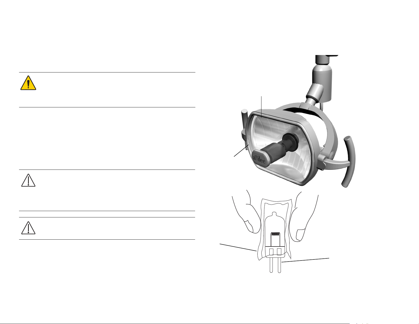
A-dec 200 Service Guide
Light Shield
Tab ( hidden)
Light Shield
New Bulb
Bulb Replacement
Follow these steps when replacing the dental light bulb:
1. Turn the light off and allow it to cool.
WARNING To avoid burning your fingers, allow the bulb to cool
before removing. Never operate the dental light with the light
shield removed. The clear shield contains UV blocking additives
and is also your protection in the unlikely event that the bulb
shatters.
2. Hold the light shield and gently squeeze one side while pulling the
shield away from the dental light. Set the light shield aside.
3. Using a gauze pad or cloth to protect your fingers, carefully pull the old
bulb from its socket. Discard the bulb.
4. Holding the new bulb in its outer wrapper, carefully insert the bulb pins
into the socket. A small section of each pin is still visible when the bulb
is fully seated.
Figure 88. Bulb Replacement
5. Remove and discard the outer wrapper. Then reinstall the light shield.
6. Verify the operation of the light by turning it on and operating it at each
88 86.0016.00 Rev A
CAUTION Take care when handling the bulb. The bulb base is
fragile and can break under excessive pressure. Do not remove the
outer wrapper when handling the new bulb. Finger oils can affect
light performance and severely limit bulb life. If you should
inadvertently touch the bulb, gently clean it with cotton
dampened with isopropyl or ethyl alcohol.
CAUTION Do not attempt to install the light shield if it has a
broken tab. Contact your authorized A-dec dealer for a
replacement shield and install it before operating the light.
intensity setting.
Page 97

Illustrated Parts Breakdown
1
2
3
Dental
This table lists the 200 Dental light parts and part numbers that correspond
to the illustration.
200 Dental Light
Item Part Number Description
1 041.709.00 Bulb
2 97.0411.00 Shield
3 90.1304.00 Light switch kit
4 90.1309.00 Light socket kit
Figure 89. Dental Light Bulb, Shield and Light Switch Kit
86.0016.00 Rev A 89
Page 98

A-dec 200 Service Guide
90 86.0016.00 Rev A
Page 99

9
TROUBLESHOOTING
The troubleshooting tables contain tips and troubleshooting information to assist in diagnosing problems. This content is not intended to cover every
situation, but includes the most common problems that you may encounter.
Dental Chair
Problem Possible Cause Action
Factory defau lt test halts
during the Base Up test,
and the circuit board beeps
one time
Chair base or back is stuck in
full up position
The limit switch is not
activated, or
Down solenoid poppet is
unable to open based on
excess hydraulic pressure
Input voltage could be low or
outside the required range.
Motor capacitor or Base Up
solenoid are defective
Potentiometer is not changing
voltage.
Hydraulic lock has occurred Correct Hydraulic Lock
Verify that the input voltage and voltage selection resistors (100 - 120 VAC = R72) and R74 (220 - 240
VAC = R 73).
If Base limit switch is activated, verify switch operation.
If the motor thermal limiter is open, and the motor is hot, wait for the motor to cool off.
Replace the motor capacitor or Base Up solenoid.
Verify the potentiometer LED comes On when the base is moving.
Check the potentiometer mechanical drive and electrical connections.
1. Remove the motor/pump cover from the chair.
2. Fit a 5/8" open end wrench to the high pressure outlet port (either lift or tilt, whichever is in
hydrostatic lock) of the hydraulic manifold.
3. Wrap a rag around both the fitting and the end of the wrench. The rag will absorb the small
amount of fluid vented from the fitting.
4. Carefully loosen the fitting about one-half turn, counterclockwise, and re-tighten.
5. Cycle the chair a couple of times to verify it is no longer in hydraulic lock.
Factory defau lt test halts
during the Back Down test,
and the circuit board beeps
one time
86.0016.00 Rev A 91
Stop plate limit switch is
activated
Verify switch operation
Page 100

A-dec 200 Service Guide
Problem Possible Cause Action
Stop plate is jammed Remove and reinstall the stop plate.
Back Down solenoid is defective Test the solenoid and replace if needed.
Back is in hydrostatic lock See Correct Hydraulic Lock, page 91
Factory default test halts
during the Back Up test
Factory default test halts
during the Base Down test
Chair moves by itself when
power is turned On
Potentiometer is not changing
voltage
Back up limit switch is activated Verify switch operation.
Back Up solenoid is defective Test solenoid and replace if needed.
Back is in hydrostatic lock See Correct Hydraulic Lock, page 91
Potentiometer is not changing
voltage.
Stop plate limit switch is
activated
Base Down solenoid is defective Test solenoid and replace if needed.
Base is in hydrostatic lock See Correct Hydraulic Lock, page 91
Potentiometer is not changing
voltage
The jumper is in FACT DEFAULT
position
Short circuit in the touchpad or
footswitch
Short circuit on the circuit board Replace the circuit board.
Verify that the potentiometer LED is On when the back is moving.
Check the potentiometer mechanical drive and electrical connections.
Verify potentiometer LED is On when base is moving.
Check potentiometer mechanical drive and electrical connections.
Verify switch operation
Verify that the potentiometer LED is On when the back is moving.
Check the potentiometer mechanical drive and electrical connections.
Verify that the jumper is in the SPARE position
Unplug the touchpad and footswitch; reset the circuit breaker. If the problem isn’t repeated, the
touchpad or footswitch may have shorted.
No power to chair or unit.
Office still has power.
92 86.0016.00 Rev A
The chair is unplugged.
The Mains On/Off button is in Off
position.
1. Verify power is available at the outlet.
2. Plug chair in to power source.
Press the Mains On/Off button.
 Loading...