

Page 1

85.0812.00, 2003 CH-1
Chairs Overview
A-dec model 1040, 1021 and 8000 chairs are electronically controlled, hydraulically powered
dental chairs. Buttons on both the touchpad and 8-button footswitch and actuators on the
8-function footswitch are used to position and program auto-positioning functions into the chair.
The hydraulic system is controlled by the electronic control module using relays and solenoidactuated valves.
This section provides information related to locating serial/model numbers, servicing,
maintenance, and adjustment of chairs. Detail on how to service chairs and troubleshoot specific
problems related to them is presented.
Page 2
Locating
Serial/Model
Number
85.0812.00, 2003 CH-2
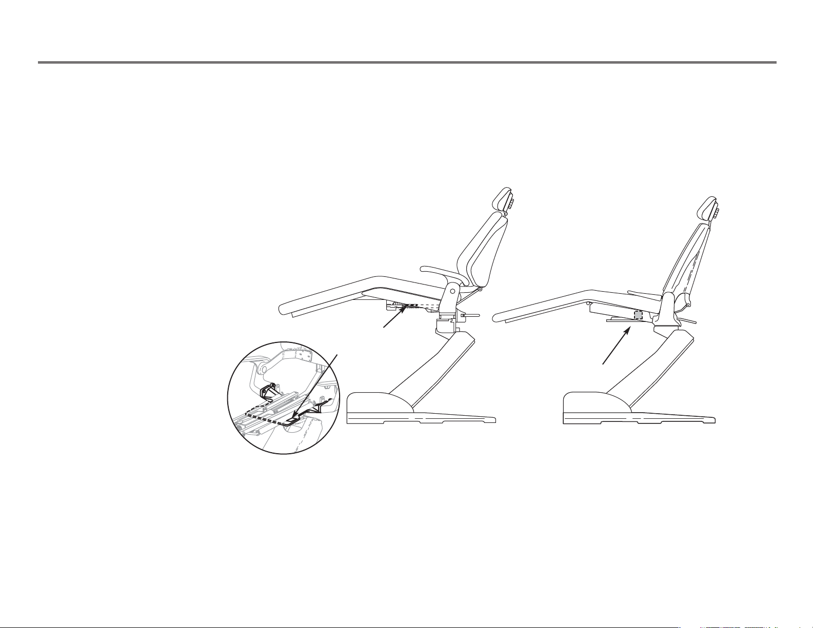
Chairs Serial/Model Number Locations
Cascade 1040 ChairDecade 1021/1011 Chair
Serial number
label location
Serial number
label location
The serial/model number tags identify the chair model and manufacture date. The label can be
found either on the top surface of a chair’s upper structure (raise the toeboard) or on the righthand side of the upper structure. If you have difficulty locating the serial/model number label,
the following example may be helpful.
Page 3
85.0812.00, 2003 CH-3
Chairs Manufacture Date
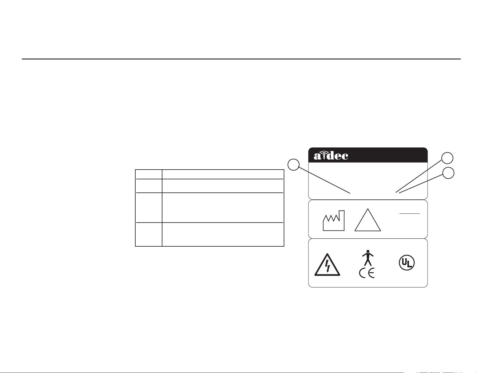
Serial/Model Number Label
Reading the
Manufacture Date
1
Item # Description
1Model number
2 The first letter of the serial number
indicates the month the product was
manufactured; e.g., A is January.
3First digit indicates the year
of manufacture.
2
1
Different models of the chair can be identified by referring to the “REF” number. Each chair is further
identified by its month and year of manufacture.
This example shows how to identify the model and month and year of manufacture of the chair.
2601 CRESTVIEW DRIVE
®
NEWBERG, OREGON 97132 USA
Designated EU Representative: A-dec Dental U.K., Ltd.
Austin House, 11 Liberty Way, Attleborough Fields,
Nuneaton, Warwickshire, England CV 116RZ
DENTAL
CHAIR
Tele: (44) 1203-350901
REF: 1040
S/N: J167856
2001
MADE IN
USA
!
DENTAL CHAIR
INPUTS
-
120 V
10 AMPS MAX
50-60 Hz
CAUTION!
U
®
LISTE
15VJ
S
D
C
LABEL P/N: 051.515.02 REV L
Page 4
85.0812.00, 2003 CH-4
Chairs Hydraulics
Working with
Hydraulics
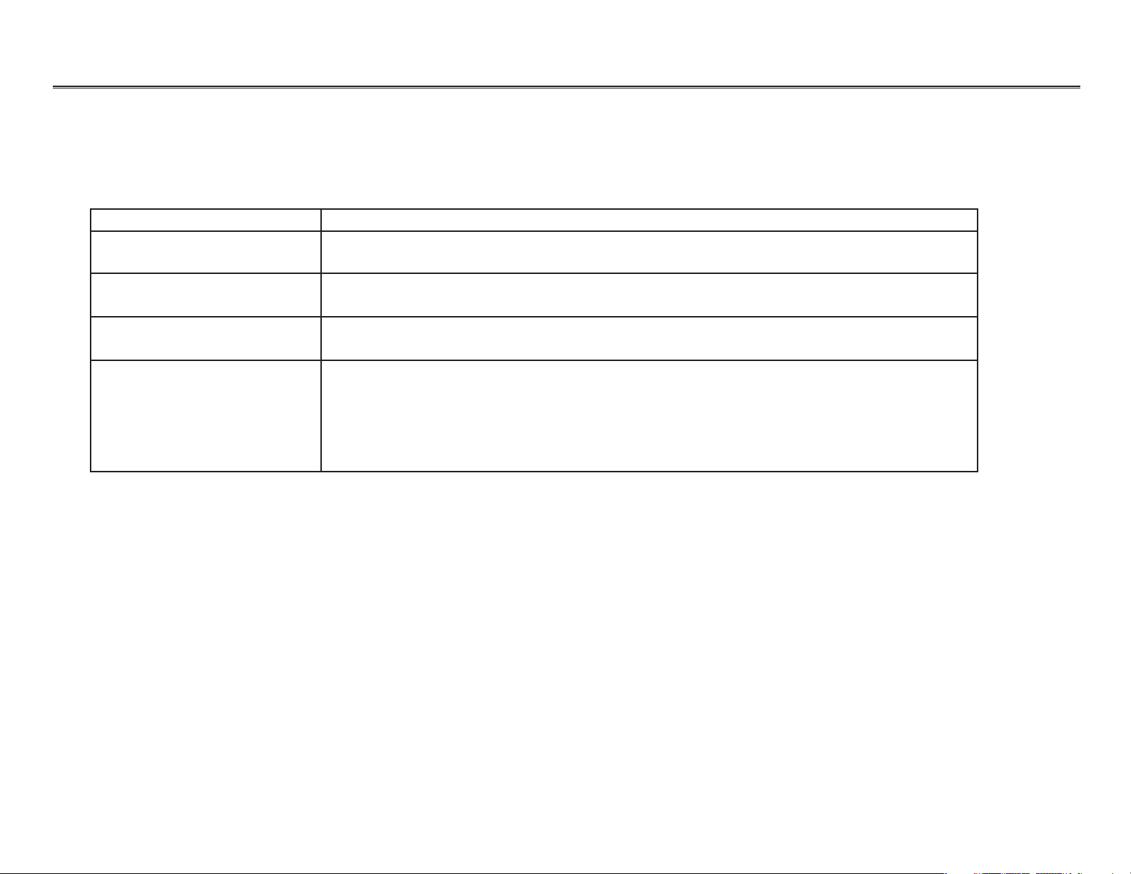
Part Description
Hydraulic fluid reservoir The fluid level in the reservoir can be seen through the sides of the reservoir and is serviced via a
top fill cap.
Hydraulic cylinders The hydraulic cylinders control the base lift and back functions. Springs and gravity retract the
rod during base and back down functions.
Motor-driven hydraulic pump The hydraulic pump and the starter capacitor supply hydraulic fluid from the reservoir, under
pressure, to the chair lift and tilt hydraulic cylinders for back up and base up functions.
Solenoid/manifold assembly This assembly gates hydraulic fluid to and from the two cylinders. Depending on the chair
function called for, the controller selects which solenoid-actuated manifold valves are opened or
closed. The solenoid/manifold assembly also includes four adjustable needle valves used to
restrict or divert the flow of hydraulic fluid to and from the lift and tilt cylinders. These valves
provide the rate of travel adjustment for chair base and back movement.
The hydraulic system consists of the following:
Page 5
85.0812.00, 2003 CH-5
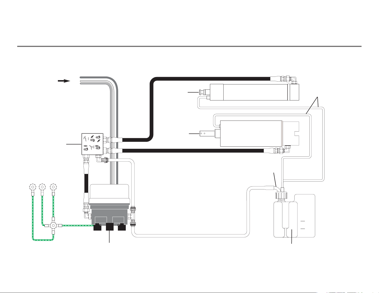
Chairs Hydraulic System Flow Diagram
From
motor/pump
start capacitor
{
Solenoid
manifold
assembly
Tilt cylinder
Lift cylinder
Vent tubes
Pickup tube
Hydraulic fluid reservoir (check fluid level with base and
back full up)
NOTE: Use only A-dec fluid P/N 61.0197.00.
Hydraulic
pump
motor
MAX
MIN
Page 6
85.0812.00, 2003 CH-6
Chairs Hydraulic Manifold
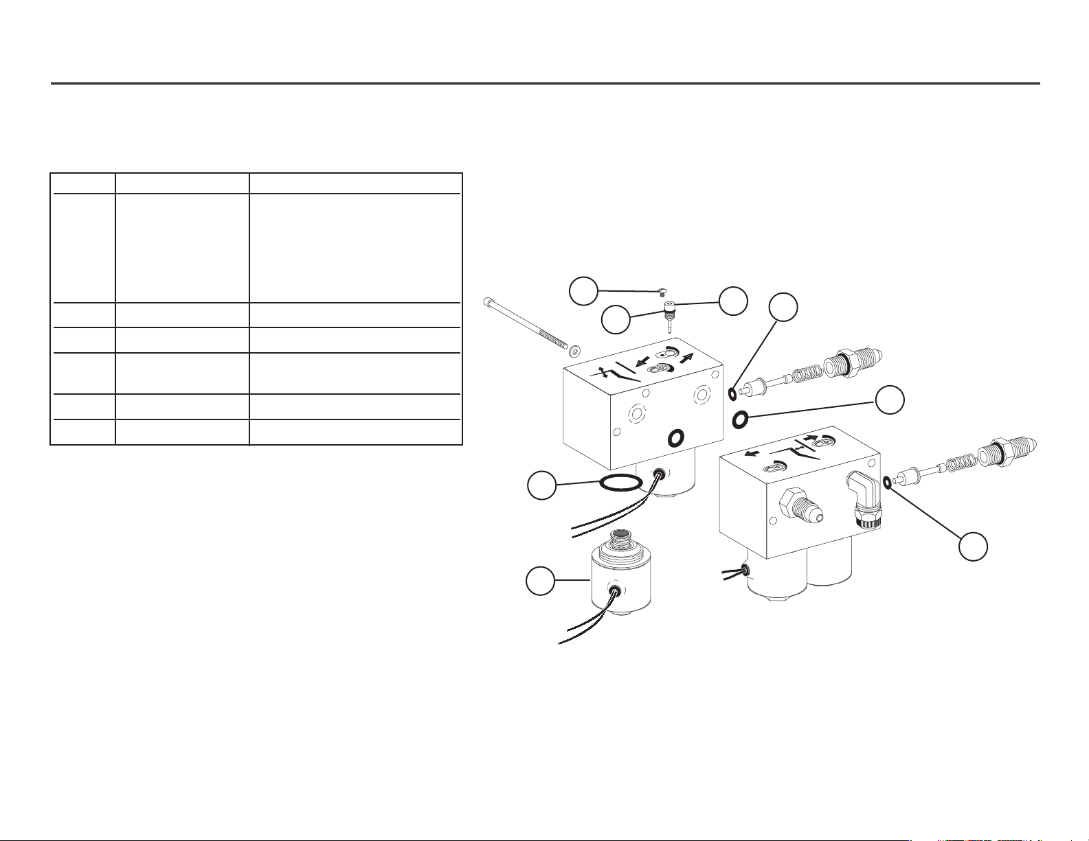
Hydraulic Manifold
Item # Part Number Description
1 61.1335.00 Solenoid, (8-watt, 100V,
Yellow wires)
61.1336.00 Solenoid, (8-watt, 120 V,
Black wires)
61.1337.00 Solenoid, (8-watt, 240 V,
Red wires)
2 035.041.02 O-ring, special pkg 10
3 030.004.02 O-ring, AS568-004 pkg 10
4 030.010.00 O-ring, AS568-010
(only on dual-block manifolds)
5 61.0460.00 Flow adjust screw with o-ring
6 001.002.00 Screw, truss-head slot
1
2
3
4
5
6
3
3
Before January 1999
Page 7
85.0812.00, 2003 CH-7
Chairs Hydraulic Manifold
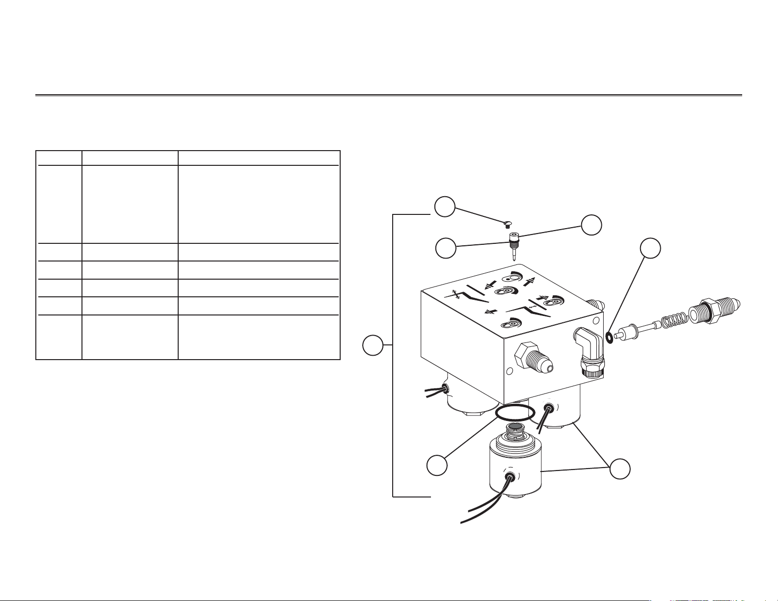
Hydraulic Manifold
Item # Part Number Description
1 61.1335.01 Solenoid, (8-watt, 100V,
Yellow wires)
61.1336.01 Solenoid, (8-watt, 120V,
Black wires)
61.1337.01 Solenoid, (8-watt, 240V,
Red wires)
2 030.015.02 O-ring, pkg 10
3 030.004.02 O-ring, AS568-004 pkg 10
4 61.0460.00 Flow adjust screw with o-ring
5 002.118.01 Screw, button-head, socket
6 61.1332.00 Manifold assy, hyd, 100V
61.1333.00 Manifold assy, hyd, 120V
61.1334.00 Manifold assy, hyd, 240V
3
4
5
2
6
1
3
After January 1999
Page 8
85.0812.00, 2003 CH-8
Chair Hydraulic Manifold
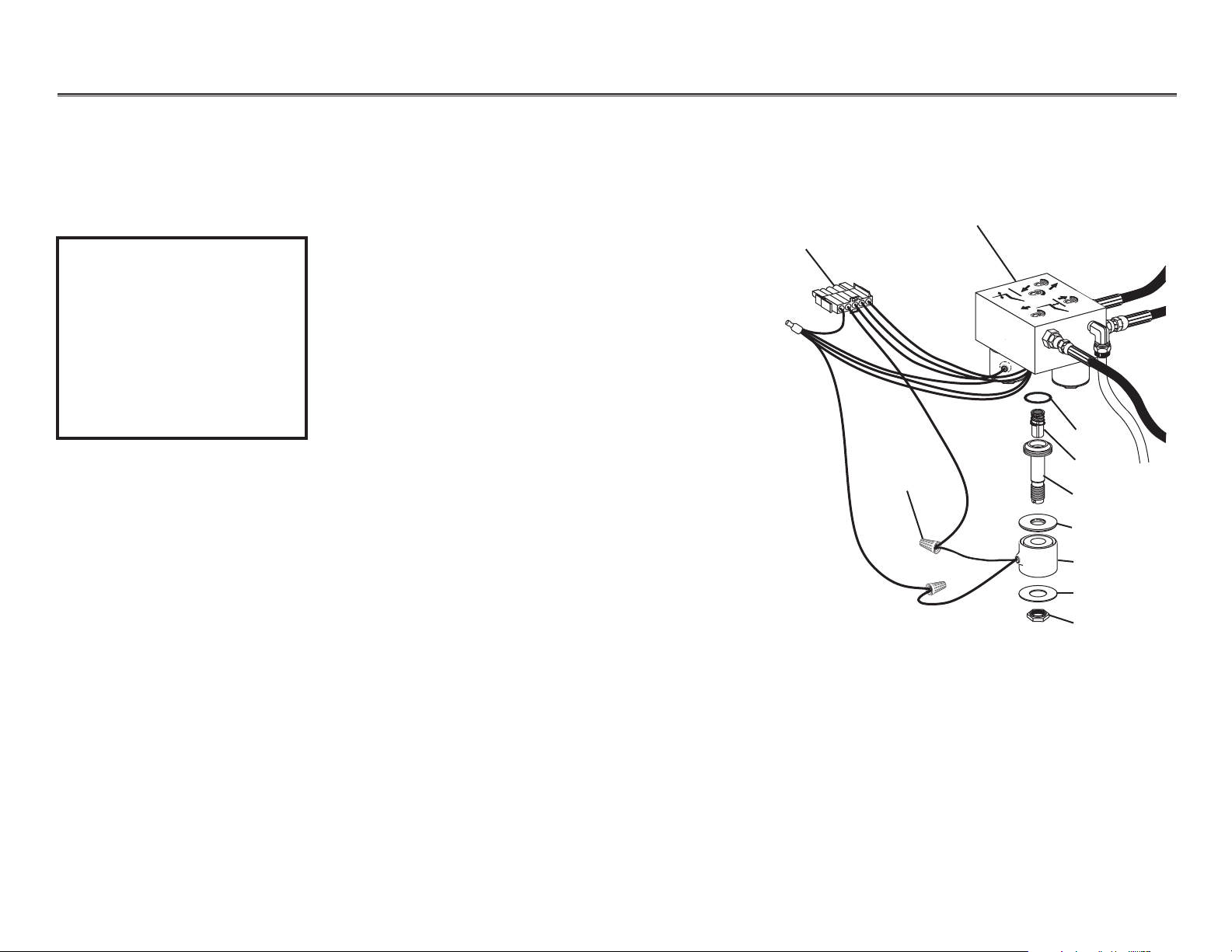
The following steps will guide you through the
removal of a solenoid.
Task Description
1 Lower the chair base and back to the
full down position to depressurize the
hydraulic system. Remove the motor
pump cover, then unplug the chair.
2 If necessary, remove the two mounting
screws that secure the manifold to the
hydraulic tray. Rotate the manifold so
the solenoids are accessible.
3Using a flat blade screwdriver and a 9/16"
wrench, remove the defective solenoid.
4 Cut the defective solenoid wires 3" (74mm)
from the coil and discard.
5Remove the old o-ring from the solenoid
cavity and completely dry the cavity.
Replace the o-ring (refer to Solenoid
installation instructions for correct o-ring).
Hydraulic manifold
O-ring
Poppet sleeve
Washer
ID washer
Retaining nut
Poppet
Coil
Wire nut
J10
Removing a
Solenoid
WARNING
The solenoid coils are
powered by line voltage
(100, 120, or 240V AC).
Failure to unplug the
chair may result in
serious injury from
electrical shock.
Removing a Solenoid
Page 9
85.0812.00, 2003 CH-9
Chair Hydraulic Manifold
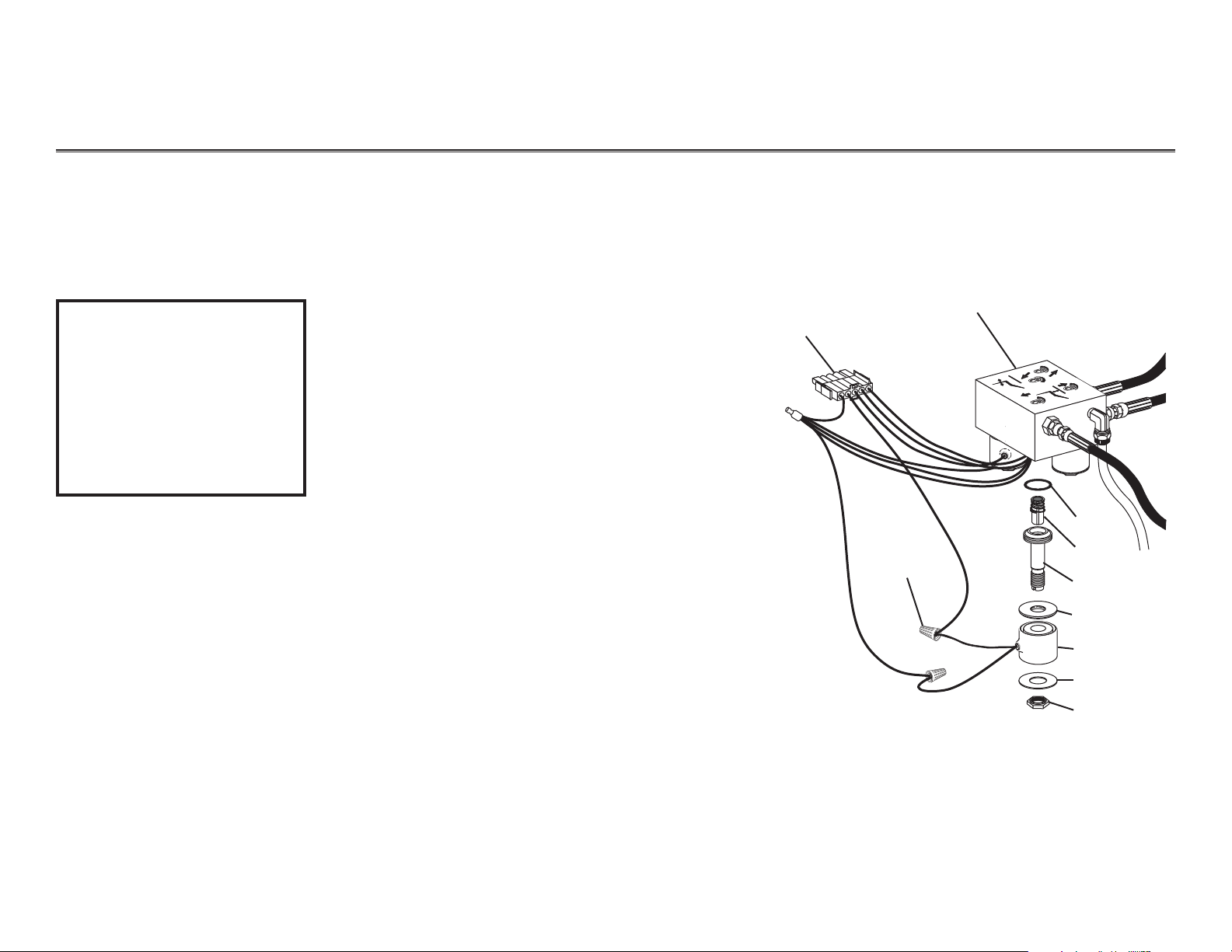
The following steps will guide you through
replacing a solenoid.
Task Description
1 Install the new solenoid stem and poppet into
the manifold and tighten to 35-40 in lb
(.11085-.2284 Nm). Position the remaining
solenoid parts on the stem and secure by
tightening the retaining nut to 25-30 in lb
(.14275-.1713 Nm).
2 Cut the solenoid wires 3" (75 mm) from the coil.
Install the stripped wires from the solenoid and
the connector housing into a wire nut. Repeat
for the remaining wire.
3Using the mounting screws, secure the
manifold to the hydraulic tray.
4. Plug in the chair. Test the chair functions to
ensure proper operations and that no fluid
leakage occurs. Reinstall the motor pump cover.
Hydraulic manifold
O-ring
Poppet sleeve
Washer
ID washer
Retaining nut
Poppet
Coil
Wire nut
J10
Replacing a
Solenoid
WARNING
The solenoid coils are
powered by line voltage
(100, 120, or 240V AC).
Failure to unplug the
chair may result in
serious injury from
electrical shock.
Replacing a Solenoid
Page 10
85.0812.00, 2003 CH-10
Chairs Hydraulic Manifold
Base down
control valve
Base up
control valve
Back down
control valve
Back up
control valve
CAUTION
Do not completely close
a speed control valve.
The motor/pump could
overheat and become
damaged from pumping
against a closed valve.
Do not remove retaining
screw from the control
valves.
Retaining
screw
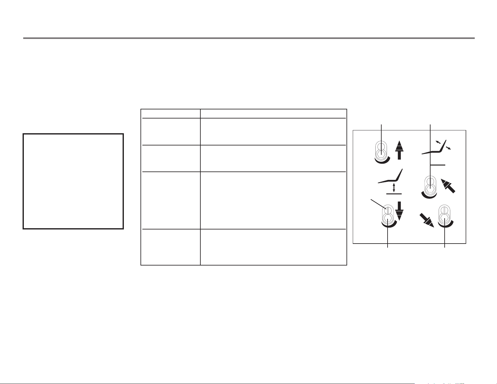
The hydraulic manifold incorporates four speed control valves, which restrict or divert the flow of
hydraulic fluid to and from the lift and tilt cylinders.
NOTE: The speed control valves are hex drive.
To adjust... Do this...
Base up speed Turn base up control valve:
clockwise to decrease speed, or
counterclockwise to increase speed.
Base down speed Turn base down control valve:
clockwise to decrease speed, or
counterclockwise to increase speed
Back up speed Turn back up control valve
counterclockwise to decrease speed, or
clockwise to increase speed.
NOTE: This is opposite of the other
three control valves. Turning the back
up valve counterclockwise too far may
prevent the back from moving up.
Back down speed Turn the back down control valve:
clockwise to decrease speed, or
counterclockwise to increase speed.
Adjusting the Hydraulic Manifold
Adjusting the
Hydraulic Manifold
Page 11
85.0812.00, 2003 CH-11
Chairs Hydraulic Manifold
Task Description
1 Remove the motor/pump cover from the chair.
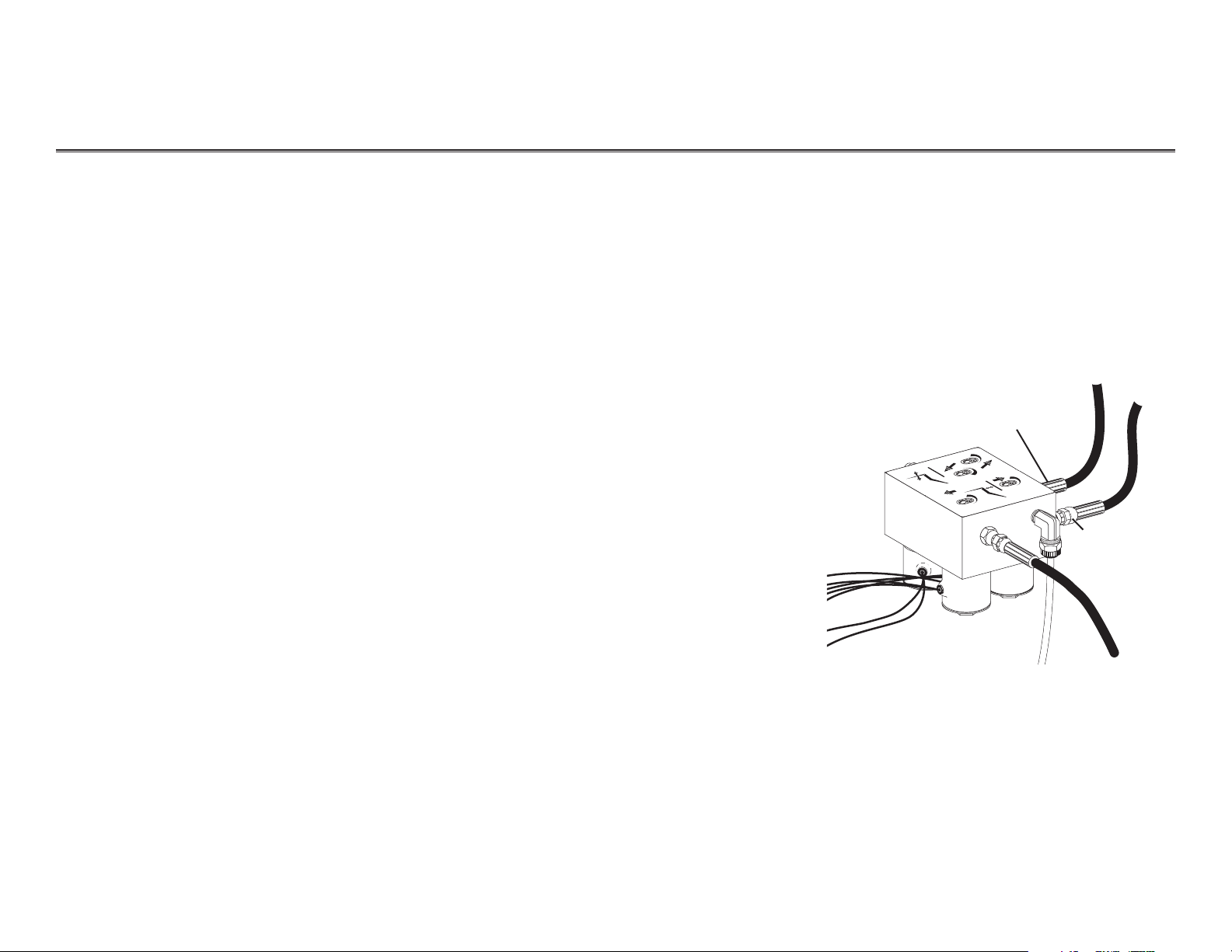
2 Fit a 5/8" wrench to the high pressure outlet port
(either lift or tilt, whichever is in hydrostatic lock) of
the hydraulic manifold. Hold the port still and use a
9/16" wrench to loosen the hose fitting.
3 Place a shop rag around the fitting to absorb
the fluid.
4 Carefully loosen the fitting counterclockwise until oil
begins to leak from the fitting. Retighten the fitting.
Operate the down function. A second release of
hydraulic fluid may be required.
5 Adjust the limit switch that caused the hydrostatic
lock (refer to Adjusting the Base Up Limit Switch). In
some cases, it may be necessary to remove and
replace the limit switch. Adjust the new limit switch
as needed. Also ensure that the large gear/actuator
is securely installed and not slipping.
6Cycle the chair a couple of times to verify it is no
longer in hydrostatic lock.
Tilt cylinder
high pressure
fitting
Lift cylinder
high pressure
fitting
Correcting
Hydrostatic
Lock
Hydraulic lock occurs based on the following conditions:
•chair base or back is stuck in full up position
• limit switch not activated, or
• down solenoid poppet is unable to open based on excess hydraulic pressure.
Correcting Hydrostatic Lock
Page 12
85.0812.00, 2003 CH-12
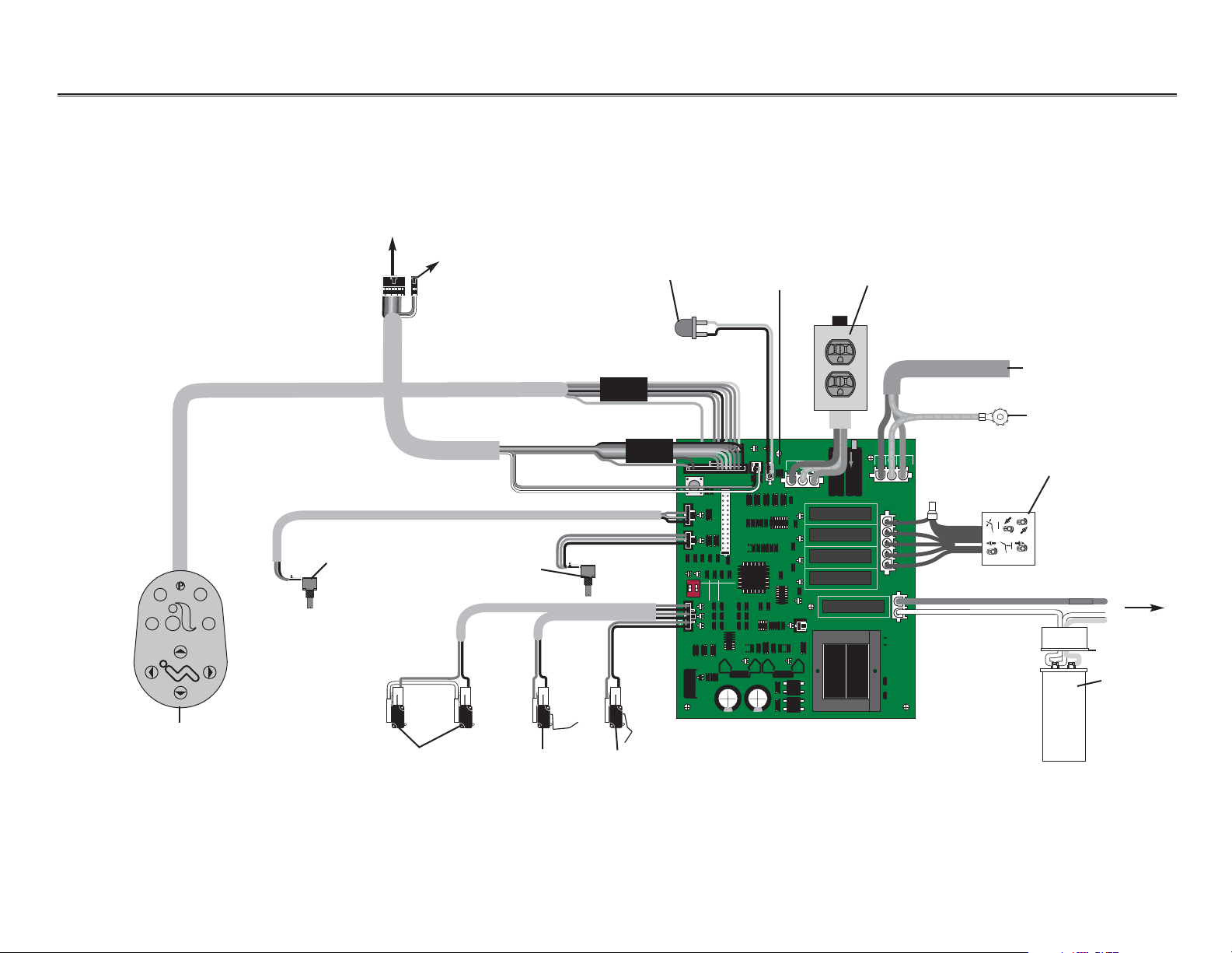
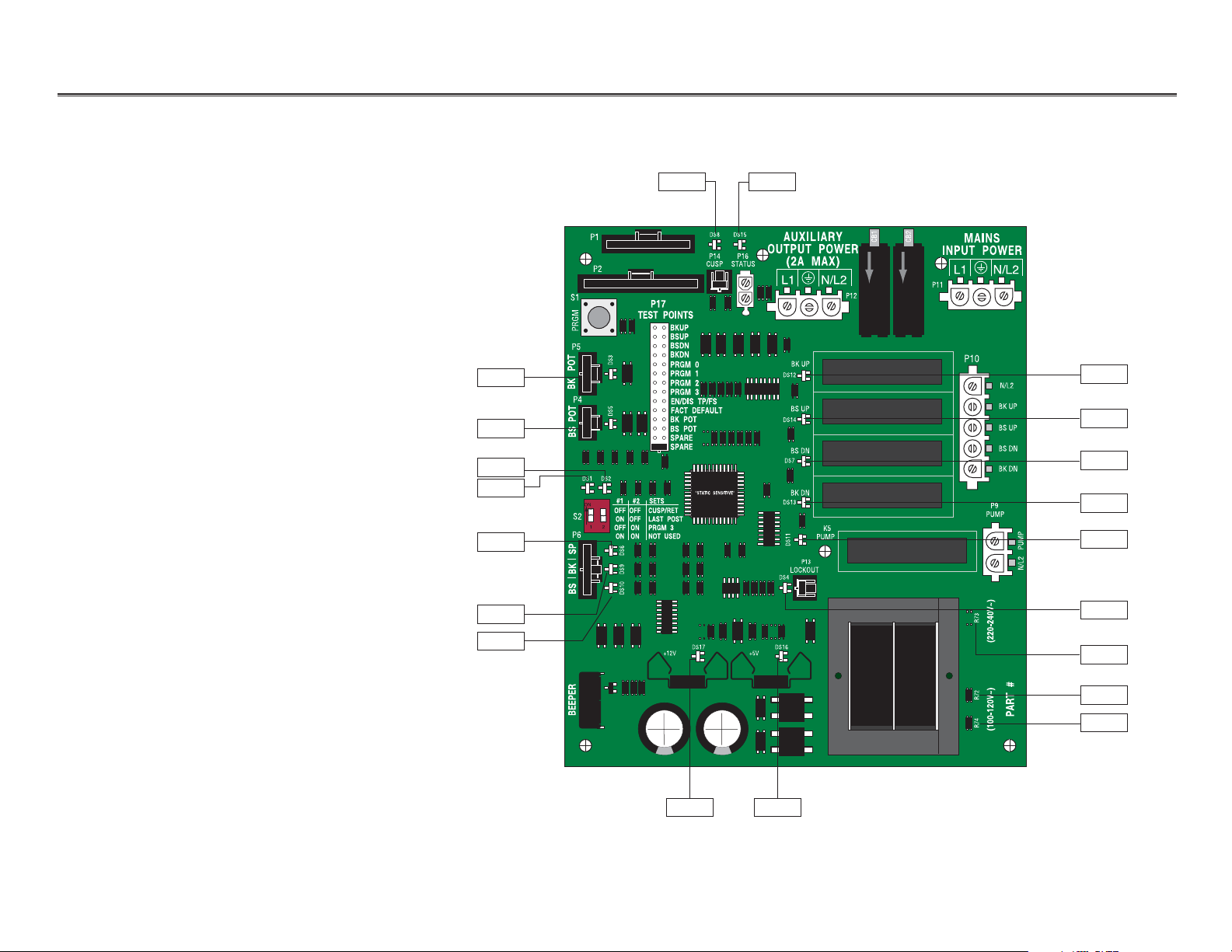
Chairs Electrical System Wiring Diagram
Optional duplex
100V and 120V only
Ground
Footswitch
LED light
Back positioning
potentiometer
Base positioning
potentiometer
Main power from
electrical outlet
Hydraulic manifold
To post box, or
Radius lift arm connector
Stop plate
limit switches
Base up limit
switch
Back up limit
switch
Capacitor
To hydraulic
motor/pump
}
To cuspidor
stop switch
NOTE: If there is no cuspidor, remove
jumper from cable and place
on board
Place jumper
here if there is
no cuspidor
DS8
P
17
BKUP
BSU
P
BSDN
BK
DN
PRGM
0
PRGM
1
PRGM
2
PRGM
3
EN/DIS TP/F
FACT DEFAU
BK POT
BS PO
T
SPAR
E
SPAR
E
"STATIC SENSITIVE
CUSP/RET
AST POS
T
L
PRGM
3
NOT USE
D
+12V +5V
P14
CUSP STATUS
S
LT
DS15
P16
"
AUXILIARY
OUTPUT POWE
(2A MAX
L1 N/L2
BK UP
DS12
BS UP
DS14
BS DN
DS7
BK DN
DS13
K5
PUMP
DS11
P13
LOCKOUT
DS4
DS16DS17
CB2
CB1
R
)
P12
MAINS
INPUT POWER
L1
P11
P10
R74 R72 R73
N/L2
N/L2
BK UP
BS UP
BS DN
BK DN
P9
PUMP
PUMP
N/L2
)
~
V
240
220
(
#
)
~
T
V
R
A
120
-
P
100
(
P1
P2
S1
TEST POINTS
PRGM
P5
T
DS3DS5
O
P
BK
P4
T
O
SP
2
1
0
3
B
DS1
DS2
#1 #2SETS
ON
O
FF
O
FF
S2
O
N
O
FF
12
O
FF
O
N
P6
O
N
O
N
SP
DS6DS9DS10
BK
S
B
R
E
P
EE
B
Page 13
85.0812.00, 2003 CH-13
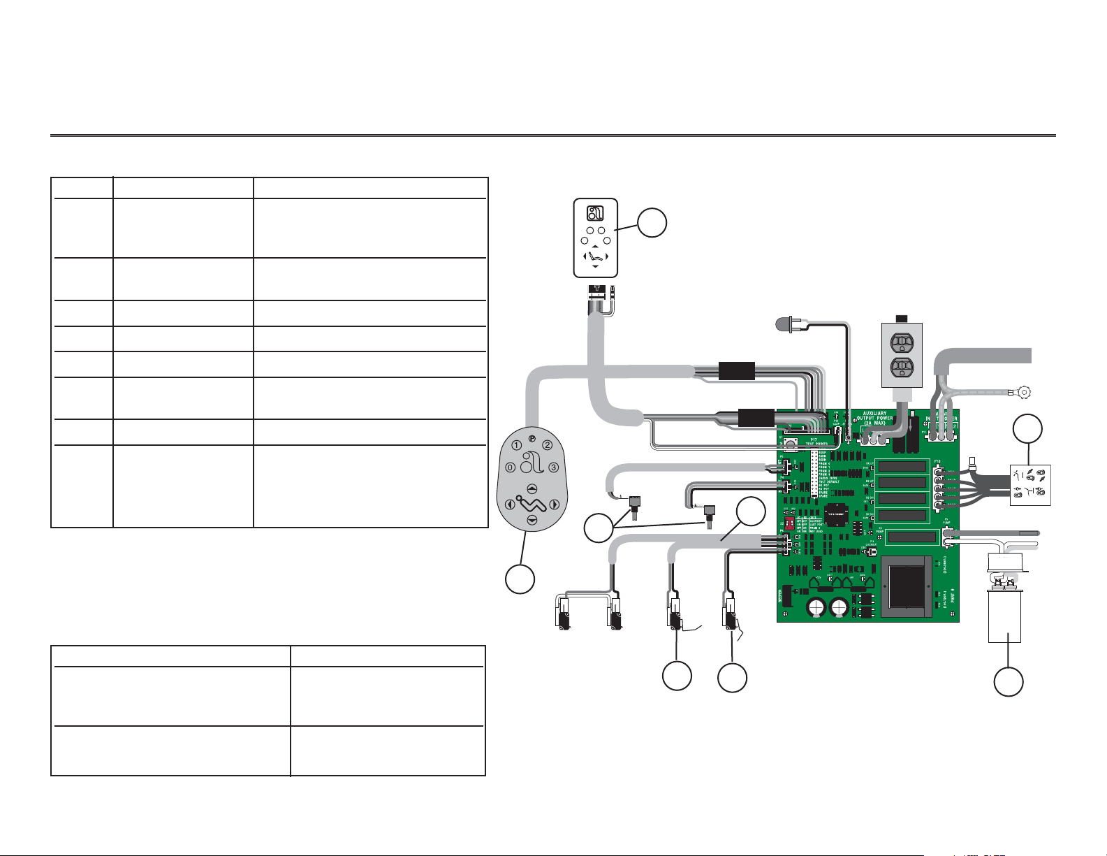
Chairs Electrical Systems Service Parts
Item # Part Number Description
1 61.1332.00 100V, Yellow wires
61.1333.00 120V, Black wires
61.1334.00 240V, Red wires
2 90.1031.00 Capacitor with boot (100-120V)
90.1034.00 Capacitor with boot (240V)
3 041.372.00 Positioning potentiometer
4 61.2065.00 Back up limit switch
5 044.184.01 Base up limit switch
6 61.2099.00 Cable assy, tilt switch
(1040) only
7 61.3043.00 8-button footswitch
8 39.1045.00 Chair touchpad
39.1385.00 Performer touchpad
39.1090.00 Cascade Master with cuspidor
39.1090.00 Cascade Master w/o cuspidor
To Replace Circuit Board P/N Order this kit
61.2510.00 90.1029.00 (100-120V)
61.1214.01
61.1373.01
61.2512.00 90.1029.01(220-240V)
61.1217.01
1
2
3
4
5
6
7
8
21
0
3
Page 14
CH-14
Chairs Diagnostic LEDs for the Circuit Board
LEDs
NOTE: Refer to Testing Factory Defaults
for more details.
DS1
DS2
DS3
DS7
DS8
DS9
DS10
DS11
DS12
DS13
DS4
DS5
DS6
DS14
DS15
DS16
DS17
R73
R72
R74
85.0812.00, 2003
Page 15

85.0812.00, 2003 CH-15
Chairs Diagnostic LEDs for the Circuit Board
LED Description Information Communicated
DS1 S2 (red DIP switch) is ON Switch is ON
DS2
DS3 Back Potentiometer LED ON Back potentiometer is functioning normally when the chair back is moving
DS4 Handpiece Lockout LED ON Lockout enabled
DS5 Base Potentiometer LED ON Base potentiometer is functioning normally when the chair base is moving
DS6 Chair Stop Plate Limit Switch LED ON Chair stop plate limit switch activated
DS7 Base Down LED Relay is ON when LED is ON and the function is moving
DS11 Pump LED
DS12 Back Up LED
DS13 Back Down LED
DS14 Base Up LED
DS8 Cuspidor Limit Switch LED ON Cuspidor limit switch activated, or jumper is missing
DS9 Back Up Limit Switch LED ON Back Up limit switch activated
DS10 Base Up Limit Switch LED ON Base Up limit switch activated
DS15 Status LED ON ON: Normal operation
OFF: Microcontroller is not functioning. Verify voltage regulator LEDs
(DS16 and DS17) are ON. Is the chair plugged in? Circuit breaker tripped?
Slow Blink: Check cuspidor (DS8) and stop plate (DS6) limit switch LEDs
Fast Blink: Check handpiece lockout (DS4) LED
Double Blink: A SPARE jumper is in the FACT DEFAULT position
DS16 5V Regulator LED OFF 1. Power to circuit board is OFF, or
2. There is a short in the cable to the base or back potentiometer. Disconnect all cables
except the power cable. Plug the cables in one at a time (the LED will turn ON when the
problem is fixed).
DS17 12V Regulator LED OFF 1. Power to circuit board is OFF, or
2. There is a short in the cable to the status light or limit switch (the LED will turn ON when
the problem is fixed).
Page 16
85.0812.00, 2003 CH-16
Chairs Chair Printed Circuit Board (PCB)
Testing and
Programming
the Circuit Board
WARNING
The chair will begin to
move automatically
during this test; to avoid
injury or equipment
damage, remove all
possible obstructions and
maintain a safe distance
from the chair. To
interrupt the chair cycle,
press any button on the
touchpad or footswitch,
or activate the chair
stop plate.
Follow these steps to test and program the chair circuit board.
Task Description
1 Insert the SPARE jumper into the FACT DEFAULT location (on P17).
Result: The chair will cycle the base and back movements and automatically
reprogram the memory positions to the factory settings
(position 0 to entry/exit; 1 and 2 to the same pre-programmed positions;
and 3 to cuspidor/return).
If the circuit board beeps three times, continue with step two.
If the circuit board beeps just once, the chair cycle has been interrupted. Diagnose
and correct any errors, then press either circuit breaker for five seconds to restart
the cycle (refer to Testing Factory Defaults).
2Move the jumper from the FACT DEFAULT location (on P17) back to the
SPARE location.
NOTE: The jumper must be in the SPARE position for normal chair functions and
safe operation.
3Press “1” on the touchpad or footswitch, or the green position on the
8-function footswitch.
Result: The chair will move to the operating position.
4Press “0” on the touchpad or footswitch, or the red button on the 8-function
footswitch.
Result: The chair will move to the entry/exit position.
NOTE: The chair programmable position buttons can be reprogrammed to the
desired positions as specified by the dental team.
Page 17
85.0812.00, 2003 CH-17
Chairs Tests
Problem Action
Factory Default test will not start
(LEDs DS15, DS16 and DS17
are Off)
Factory Default test will not start
(LED DS15 is Off; DS16 and DS17
are ON)
Factory Default test will not start
(LED DS15 is blinking; DS16 and
DS17 are ON)
If . . .
Then . . .
Transformer thermal limiter is open
Circuit breaker is tripped
Wait for transformer to cool off.
Reset circuit breaker (short circuit fault currents
may damage the circuit breaker and prevent it
from resetting).
If . . .
Then . . .
Input voltage is too low or is outside the
required range
Microcontroller is not functioning
Ve rify input voltage and voltage selection
resistors (100-120VAC=R72 and R74)
(220-240VAC=R73).
Replace the circuit board.
If . . .
Then . . .
Input voltage is too low or is outside the
required range
Microcontroller is not functioning
Ve rify input voltage and voltage selection
resistors (100-120VAC=R72 and R74)
(220-240VAC=R73).
Replace the circuit board.
Testing Factory Defaults
The table lists conditions and corrective actions for testing the factory defaults for LEDs.
Page 18
85.0812.00, 2003 CH-18
Chairs Tests
Problem Action
Factory Default test halts during
the BASE UP test and the PCB
board beeps one time
Factory Default test halts during
the BACK DOWN test and PCB
board beeps one time
If . . .
Then . . .
Input voltage is too low or is outside the
required range
Base Up limit switch is activated
Motor thermal limiter is open, motor is hot
Motor capacitor is defective
Base Up solenoid is defective
Base is in hydrostatic lock
Potentiometer is not changing voltage
Ve rify input voltage and voltage selection
resistors (100-120VAC=R72 and
R74 (220-240VAC=R73).
Verify switch operation.
Wait for motor to cool off.
Test capacitor and replace, if needed.
Test solenoid and replace, if needed.
Refer to Correcting Hydrostatic Lock.
Ve rify potentiometer LED comes ON when base
is moving.
Check potentiometer mechanical drive and
electrical connections.
If . . .
Then . . .
Stop plate limit switch is activated
Stop plate is jammed
Back Down solenoid is defective
Back is in hydrostatic lock
Potentiometer is not changing voltage
Verify switch operation.
Remove and reinstall the stop plate.
Test solenoid and replace if needed.
Refer to Correcting Hydrostatic Lock.
Ve rify potentiometer LED is ON when back
is moving.
Check potentiometer mechanical drive and
electrical connections.
Page 19
85.0812.00, 2003
CH-19
Chairs Tests
Problem Action
Factory Default test halts during
the BACK UP test
Factory Default test halts during
the BASE DOWN test
Chair moves by itself when power
is turned ON
If . . .
Then . . .
Back up limit switch is activated
Back Up solenoid is defective
Back is in hydrostatic lock
Potentiometer is not changing voltage
Verify switch operation.
Test solenoid and replace, if needed.
Refer to the Correcting Hydrostatic Lock.
Ve rify potentiometer LED is ON when back
is moving.
Check potentiometer mechanical drive and
electrical connections.
If . . .
Then . . .
Stop plate limit switch is activated
Base Down solenoid is defective
Base is in hydrostatic lock
Potentiometer is not changing voltage
Verify switch operation.
Test solenoid and replace if needed.
Refer to Correcting Hydrostatic Lock.
Ve rify potentiometer LED is ON when base
is moving.
Check potentiometer mechanical drive and
electrical connections.
If . . .
Then . . .
The jumper is in FACT DEFAULT position
Short circuit in touchpad or footswitch
Short circuit on circuit board
Verify that the jumper is in the
SPARE position.
Unplug the touchpad and footswitch; reset the
circuit breaker. If the problem isn’t repeated, the
touchpad or footswitch may have shorted.
Replace the circuit board.
Page 20

Chairs Chair Printed Circuit Board (PCB)
Raise the chair with the
stop plate limit switch
Enable and disable touchpad
and footswitch buttons
Handpiece lockout
Diagnostic LEDs
Test Points Header
Plug the chair into an electrical outlet.
Tap the chair stop plate three times within five seconds and hold on the third tap.
Result: The chair base will continue to rise as long as the stop plate is held in. This function is
automatically disabled after five minutes but is re-enabled upon each power up. To reset the
five-minute timer, depress either circuit breaker until the LEDs turn OFF, then release the
circuit breaker.
Place the SPARE jumper in the EN/DIS TP/FS position of the Test Points header P17.
Push the buttons to be Enabled or Disabled (PRGM, PRGM 0, PRGM 1, PRGM 2, PRGM 3).
Result: One beep indicates the button is disabled. Three beeps indicate the button in enabled.
Place the SPARE jumper back into the SPARE position of the Test Points header P17.
Plumb a normally open air-electric switch ( kit P/N 61.1384.00) to the air-coolant tubing (green with
long white dashes).
Insert the two position connector from the air-electric switch into P13 Lockout (next to the transformer)
See Diagnostic LEDs for the Circuit Board.
Use a SPARE jumper to test the chair manual functions (BKUP, BSUP, BSDN, BKDN).
BK POT and BS POT points allow test meter check of potentiometer voltages and
measurement of the analog DC voltage from pin 2 of the potentiometer.
Feature Programming
The chart provides information on new features and associated programming on the PCB.
CH-2085.0812.00, 2003
Identifying
New Features
Page 21

85.0812.00, 2003 CH-21
Chairs Electrical System Wiring Diagram (for PCB with no LEDs)
Item # Part Number Description
1 61.3043.00 8-button footswitch
2 041.372.00 Back positioning potentiometer
3 041.372.00 Base positioning potentiometer
4 61.2065.00 Back up limit switch
5 044.184.01 Base up limit switch
1
2
4
5
3
Back
Base
LED light
Printed
circuit
board
See next page
To post box, or Radius lift
arm connector
To cuspidor
stop switch
1
0
2
3
S1
P5
P4
S2
P14 CUSP
12
P6
TEST
POINTS
ENTR
EXIT
BSDN
BSUP
Bk DN
Bk UP
#1 #2 SETS
- - - - - - - - - - - - - - - - - - -
ON
OFF OFF sCUSP/RET
ON OFF LAST POS
OFF ON PRGM 3
P11
P1
30A, 240VAC
10A, 240VAC
30A, 240VAC
Potter & Brumfield
T90S1D12-24
Coil: 24VDC
Potter & Brumfield
T90S1D12-24
Coil: 24VDC
T90S1D12-24
Coil: 24VDC
10A, 240VAC
30A, 240VAC
30A, 240VAC
10A, 240VAC
T90S1D12-24
Coil: 24VDC
T90S1D12-24
Coil: 24VDC
9412
9412
P7
MADE IN U.S.A.
MADE IN U.S.A.
15A, 125VAC
MADE IN U.S.A.
15A, 125VAC
MADE IN U.S.A.
15A, 125VAC
5687
5687
P10
9412
Potter & Brumfield
9412
Potter & Brumfield
P12
MADE IN U.S.A.
15A, 125VAC
MADE IN U.S.A.
15A, 125VAC
P9
10A, 240VAC
10A, 240VAC
30A, 240VAC
30A, 240VAC
1243
1243
T90S1D12-24
Coil: 24VDC
T90S1D12-24
Coil: 24VDC
9412
Potter & Brumfield
9412
Potter & Brumfield
30A, 240VAC
MADE IN U.S.A.
10A, 240VAC
15A, 125VAC
30A, 240VAC
MADE IN U.S.A.
10A, 240VAC
T90S1D12-24
Coil: 24VDC
T90S1D12-24
Coil: 24VDC
15A, 125VAC
9412
Potter & Brumfield
9412
Potter & Brumfield
9412
Potter & Brumfield
T90S1D12-24
Coil: 24VDC
9412
Potter & Brumfield
T90S1D12-24
Coil: 24VDC
30A, 240VAC
30A, 240VAC
10A, 240VAC
15A, 125VAC
10A, 240VAC
15A, 125VAC
MADE IN U.S.A.
MADE IN U.S.A.
Page 22

85.0812.00, 2003 CH-22
Chairs Electrical System Wiring Diagram (for PCB with no LEDs)
From electrical outlet
Ground
Optional duplex
100V and 120V only
Item # Part Number Description
1 Hydraulic manifold with
61.1332.00 100V, Yellow wires
61.1333.00 120 V, Black wires
61.1334.00 240 V, Red wires
2 90.1031.00 Capacitor with boot (100-120V)
90.1034.00 Capacitor with boot (240V)
1
2
To hydraulic
motor/pump
See previous page
Printed circuit board
NOTE: P11 must be used
for the power cord
White
Yel low
S1
S1
P5
P5
P4
P4
S2
S2
P14 CUSP
P14 CUSP
TEST
TEST
POINTS
POINTS
ENTR
ENTR
EXIT
EXIT
BSDN
BSDN
BSUP
BSUP
Bk DN
Bk DN
Bk UP
Bk UP
#1 #2 SETS
#1 #2 SETS
- - - - - - - - - - - - - - - - - - -
- - - - - - - - - - - - - - - - - - -
ON
ON
12
12
OFF OFF sCUSP/RET
OFF OFF CUSP/RET
ON OFF LAST POS
ON OFF LAST POS
OFF ON PRGM 3
OFF ON PRGM 3
ON ON DUPLEX
ON ON DUPLEX
P6
P6
100 - 120 V
P2
P1
P1
P7
P7
115V
9412
Potter & Brumfield
T90S1D12-24
Coil: 24VDC
9412
Potter & Brumfield
MADE IN U.S.A.
10A, 240VAC
15A, 125VAC
MADE IN U.S.A.
15A, 125VAC
30A, 240VAC
9412
Potter & Brumfield
T90S1D12-24
Coil: 24VDC
9412
Potter & Brumfield
A-DEC 61-1215-00 REV L ASSY 61-1214-01 REV E
30A, 240VAC
10A, 240VAC
15A, 125VAC
5687
Potter & Brumfield
T90S1D12-24
Coil: 24VDC
30A, 240VAC
10A, 240VAC
15A, 125VAC
MADE IN U.S.A.
9412
MADE IN U.S.A.
P11P2
P12
P9
1243
P10
MADE IN U.S.A.
10A, 240VAC
15A, 125VAC
9412
Potter & Brumfield
T90S1D12-24
30A, 240VAC
Coil: 24VDC
9412
Potter & Brumfield
T90S1D12-24
Coil: 24VDC
30A, 240VAC
10A, 240VAC
15A, 125VAC
MADE IN U.S.A.
Page 23

85.0812.00, 2003 CH-23
Chairs Fuse Table for Old-style Circuit Boards (no LEDs)
Amps Description Where used Part Number
.125 3AG, Slo-Blo, 250V Chairs, 100/120V 041.360.00
.150 3AG, Slo-Blo, 250V Chairs, 240V 046.126.00
.300 3AG, Slo-Blo, 250V 1040, 1030 Chairs 100/120V 046.069.00
1010/1015/1020/1021 Chair, 120V
1010/1020 Chair, 100V
1005 Priority Chair 240V
.375 3AG, Slo-Blo, 250V Transformer 120V/24V Accessory 046.021.00
.600 3AG, Slo-Blo, 250V 1005 Priority Chair 100/120V 046.070.00
5.0 3AG, Slo-Blo, 250V Chairs 240V UK 046.100.00
Slo-Blo Fuses 3AG, 1 1/4" X 1/4" (31.75mm X 6.35mm)
Time Lag Fuses, 5mm X 20mm (1/5" X 3/4")
Actual Size
Actual Size
NOTE: There are no replaceable fuses on the following circuit boards:
90.1029.00 (100-120V) and 90.1029.01 (220-240V).
*Decade chairs after E863254; Cascade chairs after E863116
Amps Description Where used Part Number
.040 Time Lag, 250V Chairs 230V* 044.194.00
.063 Time Lag, 250V Chairs 115V* 044.193.00
6.30 Time Lag, 250V Chairs 230V* 044.147.00
10.0 Time Lag, 250V Chairs 115V* 044.192.00
Page 24

85.0812.00, 2003 CH-24
Chairs Cascade 1040 Back Positioning Potentiometer and Limit Switch
Removing the
Helical Drive Shaft
(Cascade 1040 Chair )
Task Description
1 Position the chair back full down and
remove the seat upholstery.
2Disconnect the limit switch wiring
harness from the limit switch.
3Remove the limit switch mounting
screws and limit switch from the bracket.
Lower the toeboard, if necessary, to
access the rear mounting screw. Do not
bend the switch arm.
4Remove the bracket mounting screws.
5Remove the helical drive shaft from the
potentiometer shaft. While holding the
helical shaft, reach underneath the chair
to th base of the backrest. Grasp the
bracket and pull it away from the
helical shaft.
6Remove the helical drive shaft from the
chair by moving it toward the chair
backrest and then slightly to the side to
dislodge it from the holder and guide.
Limit switch
mounting screws
Switch arm
Potentiometer
shaft
Urethane
tubing 3/8" OD
Bracket mounting
screws
Helical
drive shaft
Holder
Cascade 1040 Back Positioning Potentiometer
and Limit Switch
Tip
Follow these steps to remove the limit switch and
the helical drive shaft from the potentiometer shaft.
Page 25

85.0812.00, 2003 CH-25
Chairs Cascade 1040 Back Positioning Potentiometer and Limit Switch
Reinstalling the
Helical Drive Shaft
(Cascade 1040 Chair)
Task Description
1 Reinstall the helical drive shaft by fully inserting the tip through the guide and into the holder.
2Install the helical shaft onto the potentiometer shaft.
3 Reinstall the mounting screws, being careful not to pinch any wires.
4 Reinstall the limit switch on the bracket and reconnect it with the wiring harness.
5 Ensure the positioning potentiometer electrical connections are complete.
6 Reprogram the auto-positioning functions (refer to Programming the Chair).
7 Reinstall the upholstery.
Adjusting the
Potentiometer
(Cascade 1040 Chair)
Turn the potentiometer shaft counterclockwise
until it will no longer turn. Then turn the shaft
clockwise 1/8 of a turn.
Potentiometer Shaft
Clockwise
Setting the Back Potentiometer on the
Cascade 1040 Chair
Counterclockwise
Follow these steps to reinstall the back positioning potentiometer helical shaft and adjust the limit switch.
Page 26

85.0812.00, 2003 CH-26
Chairs Decade 1011/1021 Back Positioning Potentiometer and Limit Switch
Removing the
Helical Drive Shaft
(Decade 1011/1021 Chairs)
Task Description
1 Position the chair back full up and
remove the seat upholstery.
2Disconnect the limit switch wiring
harness from the limit switch.
3Remove the limit switch mounting
screws and limit switch from the
bracket. Do not bend the switch arm.
4Remove the bracket mounting screws.
5Remove the helical drive shaft from the
potentiometer shaft. While holding
the helical shaft, reach underneath the
chair to the base of the backrest. Grasp
the bracket and pull away from the
helical shaft.
6Remove the helical drive shaft from the
chair by moving it toward the chair
backrest and then slightly to the side to
dislodge it from the holder and guide.
Limit switch
mounting screws
Switch arm
Potentiometer
shaft
Urethane
tubing 3/8" OD
Bracket mounting
screws
Helical
drive shaft
Decade 1011/1021 Back Positioning
Potentiometer and Limit Switch
Tip
Follow these steps to remove the limit
switch and helical drive shaft from the chair.
Page 27

85.0812.00, 2003 CH-27
Chairs Decade 1011/1021 Back Positioning Potentiometer and Limit Switch
Reinstalling the
Helical Shaft
(Decade 1011/1021
Chairs)
Task Description
1 Reinstall the helical drive shaft by fully inserting the tip through the guide and into the holder.
2Install the helical shaft onto the potentiometer shaft.
3 Reinstall the mounting screws, being careful not to pinch any wires.
4Reinstall the limit switch on the bracket and reconnect it with the wiring harness.
5 Ensure the positioning potentiometer electrical connections are complete.
6 Reprogram the auto-positioning functions (refer to Programming the Chair).
7 Reinstall the upholstery.
Turn the potentiometer shaft clockwise until
it will no longer turn. Then turn the shaft
counterclockwise 1/8 of a turn.
Potentiometer shaft
Counterclockwise
Setting the Back Potentiometer on the
Decade 1011/1021 Chair
Clockwise
Follow these steps to reinstall the back positioning potentiometer helical shaft and to reposition the
limit switch.
Adjusting the
Potentiometer
(Decade 1011/1021 Chairs)
Page 28

85.0812.00, 2003 CH-28
Chairs Cascade and Decade Base Positioning Potentiometer
Working with the
Back and Base
Positioning
Potentiometers
The back and base positioning potentiometers (pots) perform two tasks for the controller:
•Provide the controller with a voltage level representing the current position of the chair base and back.
The voltage level is stored by the controller for later reference during auto-positioning.
•Tell the controller where the chair base and back are currently positioned. The controller compares the
current voltage level to the voltage level stored during auto-positioning programming.
The base positioning pot is gear-driven by movement of the chair lift arm. The back positioning pot is
driven by movement of the chair back.
Page 29

85.0812.00, 2003 CH-29
Chairs Cascade and Decade Base Positioning Potentiometer
Adjusting the
Base Positioning
Potentiometer
Task Description
1 Remove the motor/pump cover and
position the chair base down.
2Remove the mounting screw.
3Turn the potentiometer gear clockwise
until it stops.
4Align the potentiometer assembly, then
turn the potentiometer gear
counterclockwise two teeth (relative to
one tooth on the large drive gear).
5 Ensure all electrical connections to the
limit switch and positioning
potentiometer are properly connected
6Raise the chair base while observing the
two gears for binding.
7Reinstall the motor/pump cover
and reprogram the pre-positioning
functions.
Limit switch
Large drive
gear
Potentiometer gear
Positioning
potentiometer
Mounting
screw
Clockwise
Counterclockwise
Adjusting the Base Positioning Potentiometer
Base down
Follow these steps to adjust the base positioning potentiometer.
NOTE: Do not raise the base to full up
until you have adjusted the base
up limit switch (see Adjusting
the Base Up Limit Switch).
Page 30

85.0812.00, 2003 CH-30
Chairs Cascade and Decade Base Positioning Potentiometer
2
1
3
Item # Part Number Description
1 041.372.00 Potentiometer w/nut
5K ohm, +20%, 1W
2 044.184.01 Limit switch, modified
3 61.1295.00 Gear, 24 pitch 30 tooth
4 61.1222.00 Potentiometer gear
Replacing Base Positioning Potentiometer,
Limit Switch and Gears
4
Base Positoning Potentiometer
Page 31

85.0812.00, 2003 CH-31
Chairs Cascade and Decade Base Up Limit Switches
Working with the
Back Up and Base
Up Limit Switches
The chair base and back up limit switches detect when the maximum allowed up travel is reached.
The two limit switches are normally closed enabling the base and back up relay circuits. If an up limit
switch is opened, two things occur:
•The base or back up function relay is disabled causing the up function solenoid to shut off the
flow of hydraulic fluid to the cylinder.
• The controller, sensing that a back up or base up relay has been disabled, turns off the
hydraulic pump.
The base up limit switch is actuated by a pin located on the positioning potentiometer drive gear.
The back up limit switch is actuated by a glide block, which is part of the back tilt mechanism.
Page 32

85.0812.00, 2003 CH-32
Chairs Cascade and Decade Base Up Limit Switches
Adjusting the Base
Up Limit Switch
NOTE: For correct limit switch actuation,
the actuator tab on the large gear
should be at approximately the 5:30
clock position when the chair is full
base down.
Task Description
1 Remove the motor/pump cover.
2 Loosen the two screws clamping the
limit switch to the mounting bracket.
3 Position the chair base up until
the distance from the floor to the
base of the upper chair casting is
23" (584mm).
4 Push the limit switch against the
actuator on the drive gear until the
switch opens (clicks).
5Tighten the clamping screws, making
sure they do not hit the gear.
6Lower the chair base down until the
limit switch has closed, then raise the
chair full base up. Check the distance
between from the floor to the base of
the upper chair casting to ensure it is
23" (584mm).
Raising the Chair to the Correct Base Up Height
Adjusting the Base Up Limit Switch
23"
584mm
Limit switch
Switch arm
Mounting
bracket
Actuator
Clamping
screws
NOTE: Positioning
potentiometer
omitted for clarity.
Follow these steps for adjusting the base up limit switch.
Page 33

85.0812.00, 2003 CH-33
Chairs Auto-Positioning
Programming
the Chair
Task Description
1Use the footswitch or touchpad to set the chair at the
desired position for base and back.
2Press and release the program button.
Result: You will hear a single beep.
3Within four seconds, press an automatic position button
(0, 1, 2, or 3) on the footswitch or touchpad to store the
chair position. On an 8-function footswitch, move the
actuator to the desired position.
Result: You will hear three beeps confirming that
the function has been programmed.
NOTE: PCBs manufactured before 1994, do not beep.
Test the programming by trying it.
Performer III Touchpad
8-Button Footswitch8-Function Footswitch
Left
actuator
Right
actuator
Pre-position (1)
Pre-position (2)
Entry/Exit (0)
Cuspidor/return,
last position, or
pre-position (3)
Program
button
Program
button
Program
button
Base up
Back down
Back up
Base down
Programmable
position (1)
Programmable
entry/exit (0)
Programmable
position (2)
Cuspidor
return (3)
Base up
Back up
Base down
Back down
Replacement membrane P/N 61.2189.00
Replacement membrane P/N 61.3048.00
Follow these steps to set the auto-positioning for the chair.
Chair Touchpad
Program
button
Programmable
position (1)
Programmable
entry/exit (0)
Cuspidor
return (3)
Back down
Base up
Back up
Base down
Programmable
position (2)
21
0
3
1
0
2
3
1
0
2
3
Page 34

85.0812.00, 2003 CH-34
Chairs Function 3 Programming
Programming
Function 3
Function
Programming
Cuspidor/Return
NOTE: Chairs with S/N J467728
and later are factory set with
function 3 as cuspidor/return
Last Position
Programmable Position
NOTE: Chairs up to S/N J467727
are factory set with function 3
as a programmable position
Description
Switches 1 and 2 are OFF.
Switch 1 is ON and switch 2 is OFF.
Go back and forth between two
positions by momentarily moving
the righthand actuator on the
8-function footswitch to position 3 or
pressing number 3 on the touchpad or
8-button footswitch.
Switch 1 is OFF and switch 2 is ON.
Move the chair to the desired position.
Press and release the program button.
After the beep, push button 3 on the
touchpad or 8-button footswitch or
move the actuator to position 3 on the
8-function footswitch. The single beep
confirms the position is programmed.
Used to raise the chair back to a
programmable upright position
providing the patient access to the
cuspidor. Momentarily pushing button 3
on the touchpad or 8-button footswitch,
or moving the actuator to position three
on the 8-function footswitch, returns the
back to the previous position.
Anon-programmable position that
simply moves the chair base and back to
their previous positions.
This option is used to set the base and
back to a predesignated
position. It allows this function to be
programmed like 0, 1, and 2.
Switch 2
Function 3 DIP Switch
before 2000
Switch 1
Before 2000
1 2
ON
Page 35

85.0812.00, 2003 CH-35
Chairs Function 3 Programming
Switch 1
Switch 2
Function 3 DIP Switch
after 2000
Programming
Function 3
Function
Programming
Cuspidor/Return
Last Position
Programmable Position
Description
Both switches 1 and 2 are OFF.
Switch 1 is ON and switch 2 is OFF.
Go back and forth between two
positions by momentarily pushing the
right hand rocker button to position 3
or pressing number 3 on the touchpad.
Switch 1 is OFF and switch 2 is ON.
Move the chair to the desired position.
Press and release the program button.
After the tone, push button 3 on the
touchpad or footswitch or move the
actuator to position 3 on the 8-function
footswitch. The audible tone confirms
the position is programmed.
Used to raise the chair back to a
programmable upright position
providing the patient access to the
cuspidor. Momentarily pushing button 3
on the touchpad or 8-button footswitch,
or the actuator to position 3 on the
8-function footswitch will return the
back to the previous position.
Anon-programmable position that
simply moves the chair base and back
to their previous positions.
Used to set the base and back to a
predesignated position.
After 2000
Page 36

85.0812.00, 2003 CH-36
Chairs Cascade 1040 Vac Back Floor Box with Utilities
Air
Water
Water shutoff valve
Circulating
syringe drip
tube
NOTE: Ribbed tubing is
connected to pilot air
To/from vac back
assistant’s
instrumentation
}
Item # Part Number Description
1. 33.0048.04 Valve, toggle, 3-way, ON/OFF
2. 24.0100.03 Pressure indicator
2
1
Page 37

85.0812.00, 2003 CH-37
Chairs Cascade 1040 Vac Back Assistant’s Instrumentation
HVE valve
Vacuum canister
Saliva ejector
NOTE: Ribbed tubing connects
to syringe air
To/from floor box
2
1
{
Item # Part Number Description
1 23.0172.00 Pinched valve assy, single
2 23.1011.00 Syringe head assy
Page 38

85.0812.00, 2003 CH-38
Chairs Water Shutoff Valve and 3-way Toggle Valve
Item # Part Number Description
1 24.0137.01 9-hole gasket, pkg 10
2 013.032.00 Spring, conc, comp, .260/.350 OD
3 24.0132.00 Piston with O-ring, Delrin
4 24.0440.02 Diaphragm, pkg 10
Item # Part Number Description
1 33.0031.01 Toggle with pin, Gray
2 29.0840.00 Stem with O-rings, 3-way
3 22.0040.00 Spring, comp., .300 OD x .40
1
2
3
4
1
2
3
Water Shutoff Valve
34.0031.00
3-Way Toggle Valve
33.0048.04
Page 39

85.0812.00, 2003 CH-39
Chairs Glide Bar Tension Block and Swivel Brake
Item # Part Number Description
1 61.1569.00 Wearpad, sliding wedge
Cascade 1040 Glide Bar Tension Block
Decade 1011/1021 Glide Bar Tension Block
Cascade 1040 Swivel Brake
61.2055.00
Item # Part Number Description
1 61.1569.00 Wearpad, sliding wedge
Item # Part Number Description
1 61.1228.00 Thrust washer-brake pad assy
2 61.2227.00 Nut-brake pad assy
Decade 1011/1021 Swivel Brake
61.1538.01
Item # Part Number Description
1 61.1537.01 Replacement brake pads
2
1
1
1
1
Page 40

85.0812.00, 2003 CH-40
Chairs Double-Articulating Headrest
Adjusting the
DoubleArticulating
Headrest
Adjust Cascade 1040 Headrest
Glide Bar Tension
Double-Articulating Headrest
61.2265.00
Item # Part Number Description
1 61.2116.XX Double articulating
headrest upholstery
— 61.3046.00 Conversion kit, 1040
screw-on headrest
cushion. Applies to
chairs with the wire
formed headrest cushion
(S/N E442969 and before).
1
Upholstery
Replacement
Follow these steps to adjust the headrest.
Task Description
1 Adjust the glide bar until the headrest moves freely yet
maintains its position.
2Turn the screw clockwise to increase friction and hold
the headrest more securely.
3Turn the screw counterclockwise to decrease
friction and allow the headrest to move up and down
more freely. The Decade chair adjustment screw is
located in back of the glide bar.
NOTE: Use a phillips head screwdriver to adjust the glide
bar tension. You may need to remove the back
upholstery to access the adjustment screw.
Page 41

85.0812.00, 2003 CH-41
Chairs
Problem Action
Chair is inoperative
1 Do any relays on the printed circuit board click? Refer to Testing Relay Click.
YES: Go to step 2.
NO: Go to step 3.
2 Is the base/back all the way down?
YES: Go to Base or Back Up Function is Inoperative.
NO: Go to step 3.
3Has the solenoid fuse blown (120V only)?
YES: Replace the fuse. Check for shorted solenoids or shorted wiring to the solenoids (refer to
Testing Solenoid Continuity and Testing Wiring Harness Continuity). Retest chair functions.
NO: Go to step 4.
4 Complete the steps outlined in Testing Magnetic Pull. Is there magnetic pull at each solenoid?
YES: Go to step 5.
NO: Remove and replace the faulty solenoid (refer to Removing a Solenoid and
Replacing a Solenoid). Retest chair functions.
5 Is the chair in hydrostatic lock?
YES: Remedy hydrostatic lock (refer to Correcting Hydrostatic Lock). Retest chair functions.
NO: Check for and replace a faulty manifold or valve.
Troubleshooting
PCBs with no LEDs
Diagnostic information is presented in the following charts.
Page 42

85.0812.00, 2003 CH-42
Chairs Troubleshooting (for PCB with no LEDs)
Problem Action
6Is the printed circuit board fuse(s) blown?
YES: Remove and replace the fuse, then check the potentiometer wiring for damage, shorts, or
improper wiring. If the fuse blows again, disconnect the potentiometer wiring at P4 and
P5 on the printed circuit board. If the fuse still blows, remove and replace the printed
circuit board. Otherwise remove and replace the potentiometer wiring.
NO: Check the condition of the stop plate limit switches and wiring. Check the printed
circuit board connector P6 (limit switches). Unplug the chair from its power outlet and
plug it in again. If the chair is still inoperative, make sure there is power at the outlet. If
the preceding steps do not solve the problem, go to step 7.
7Disconnect the footswitch and, if installed, the touchpad. Use the printed circuit board test points to
activate chair up functions (refer to Using Chair Test Points). Does the chair work now?
YES: If there is a footswitch only, remove and replace the footswitch. If there is a touchpad
only, remove and replace the touchpad. If there is both a footswitch and touchpad,
go to step 8.
NO: The printed circuit board is faulty, remove and replace the printed circuit board.
8Reconnect the footswitch to the printed circuit board. Using the footswitch, operate the chair. Does
the chair work properly?
YES: Remove and replace the touchpad.
NO: Go to step 9.
9Reconnect the touchpad to the printed circuit board. Using the touchpad, operate the chair. Does the
chair work properly?
YES: Remove and replace the footswitch.
NO: The printed circuit board is faulty, remove and replace the printed circuit board.
Chair is inoperative
Page 43

Problem Action
85.0812.00, 2003 CH-43
Chairs Troubleshooting (for PCB with no LEDs)
1 Is the chair base or back up?
YES: Go to step 2.
NO: Go to step 3.
2Has the up limit switch activated (opened)? Refer to Testing Limit Switch Continuity and
Testing Limit and Stop Switches Voltage.
YES: Normal chair operation, check base up limit switch adjustment
(refer to Adjusting the Base Up Limit Switch). The back up limit switch is not adjustable.
NO: The chair may be in hydraulic lock. Remedy the hydrostatic lock
(refer to Correcting Hydrostatic Lock).
3Has the solenoid fuse blown (120V only)?
YES: Replace the fuse. Complete Testing Solenoid Continuity.
Replace shorted solenoids or shorted wiring to the solenoids, as necessary.
NO: Go to step 4.
4 Is the motor/pump hot?
YES: Wait 20 minutes for the thermal limiter to reset. If the Up function works, check for other
problems. If the Up function is still inoperative, go to step 5.
NO: Go to step 5.
5 Does a relay on the printed circuit board click (refer to Testing Relay Click)?
YES: Go to step 6.
NO: Go to step 7.
6 Complete the steps outlined in Testing Magnetic Pull. Is there magnetic pull at the solenoid?
YES: Go to step 12.
NO: The solenoid is faulty. Remove and replace the solenoid
(refer to Removing a Solenoid and Replacing a Solenoid).
Base or back up function
is inoperative
Page 44

Problem Action
Base or back up function
is inoperative
85.0812.00, 2003 CH-44
Chairs Troubleshooting (for PCB with no LEDs)
7Disconnect the footswitch and, if installed, the touchpad. Use the printed circuit board test points to
activate chair up function (refer to Using Chair Test Points). Does a relay on the printed circuit board
click (refer to Testing Relay Click)?
YES: Go to step 8.
NO: Go to step 10.
8 Does the UP function work?
YES: If there is a footswitch only, remove and replace the footswitch. If there is a touchpad
only, remove and replace the touchpad. If there is both a footswitch and touchpad,
go to step 9.
NO: Go to step 11.
9Reconnect the footswitch to the printed circuit board. Using the footswitch, operate the chair. Does
the UP function work?
YES: Remove and replace the touchpad.
NO: Go to step 10.
10 Reconnect the touchpad to the printed circuit board. Using the touchpad, operate the chair. Does the
UP function work?
YES: Remove and replace the footswitch.
NO: Go to step 11.
11 Complete the steps for Testing Magnetic Pull. Is there magnetic pull at the solenoid?
YES: Go to step 14.
NO: Remove and replace the faulty solenoid(s) (refer to Removing a Solenoid and
Replacing a Solenoid).
Page 45

Problem Action
85.0812.00, 2003 CH-45
Chairs Troubleshooting (for PCB with no LEDs)
Base or back up function
is inoperative
12 Is the limit switch faulty or open (refer to Testing Limit Switch Continuity and
Testing Limit and Stop Switches Voltage)?
YES: Adjust or remove and replace the limit switch. Adjust the base up limit switch
(refer to Adjusting the Base Up Limit Switch).
NO: Go to step 13.
13 Is the limit switch wiring faulty (refer to Testing Wiring Harness Continuity)?
YES: Repair or replace the limit switch wiring.
NO: Unplug the chair and plug it back in. If the problem remains, the printed circuit board is
faulty, replace the printed circuit board.
14 Is there an open in the limit switch wiring (refer to Testing Wiring Harness Continuity)?
YES: Repair or replace the wiring.
NO: Go to step 15.
15 Is the base up limit switch out of adjustment?
YES: Adjust the limit switch (refer to Adjusting the Base Up Limit Switch). The back up limit
switch is not adjustable.
NO: Go to step 16.
16 Is there noise from the motor/pump?
YES: Go to step 17.
NO: Go to step 18.
Page 46

85.0812.00, 2003 CH-46
Chairs Troubleshooting (for PCB with no LEDs)
Problem Action
Base or back up function
is inoperative
Base or back down
function is inoperative
17 Is the motor current more than 5 Amps (refer to Testing the Motor/Pump)?
YES: The motor/pump is faulty. Remove and replace the motor/pump.
NO: Remove and replace the motor/pump capacitor. Test the Up function. If it still does not
work,the manifold is faulty. Remove and replace it.
18 Is there an open or short in the motor/capacitor wiring (refer to Testing Wiring Harness Continuity)?
YES: Contact an A-dec customer service representative for proper repair procedures of the
motor/pump capacitor wiring.
NO: The printed circuit board is faulty, remove and replace the printed circuit board.
1Try an Up function first, then a Down function. Is the base or back still up?
YES: Go to step 2.
NO: Go to step 3.
2Has the limit switch activated (opened) (refer to Testing Limit Switch Continuity and Testing Limit and
Stop Switches Voltage)?
YES: Go to step 3.
NO: The chair may be in hydrostatic lock. Remedy hydrostatic lock
(refer to Correcting Hydrostatic Lock). Retest chair functions.
3 Does a relay on the printed circuit board click (refer to Testing Relay Click)?
YES: Go to step 7.
NO: Go to step 4.
Page 47

85.0812.00, 2003 CH-47
Chair Troubleshooting (for PCB with no LEDs)
Problem Action
Base or back down
function is inoperative
4Disconnect the footswitch and, if installed, the touchpad. Use the printed circuit board test points to
activate chair down functions (refer to Using Chair Test Points). Does the down function work?
YES: If there is a footswitch only, remove and replace the footswitch. If there is a touchpad
only, remove and replace the touchpad. If there is both a footswitch and touchpad,
go to step 5.
NO: Check condition of stop and/or cuspidor limit switches and wiring (refer to Testing Limit
and Stop Switches Voltage, Testing Limit Switch Continuity, and Testing Wiring Harness
Continuity). Check the printed circuit board connector P6 (limit switches). Unplug the
chair and plug it back in. If the problem remains, the printed circuit board is faulty.
Replace the printed circuit board.
5Reconnect the footswitch to the printed circuit board. Using the footswitch, operate the chair. Does
the chair down function work?
YES: Remove and replace the touchpad.
NO: Go to step 6.
6Reconnect the touchpad to the printed circuit board. Using the touchpad, operate the chair. Does the
chair down function work?
YES: Remove and replace the footswitch.
NO: Check condition of stop switch and/or cuspidor limit switch and wiring (refer to Testing
Limit and Stop Switches Voltage, Testing Limit Switch Continuity, and Testing Wiring Harness
Continuity). Check the printed circuit board connector P6 (limit switches). Unplug the
chair and plug it back in. If the problem remains, the printed circuit board is faulty.
Replace the printed circuit board.
7 Complete the steps for Testing Magnetic Pull. Is there magnetic pull at each solenoid?
YES: Replace faulty manifold/valve.
NO: Go to step 8.
8Has the solenoid fuse blown (120V only)?
YES: Replace the fuse. Complete the steps for Testing Solenoid Continuity. Replace shorted
solenoids or shorted wiring to the solenoids as necessary.
NO: Replace the faulty solenoid.
Page 48

85.0812.00, 2003 CH-48
Chairs Troubleshooting (for PCB with no LEDs)
Problem Action
Back moves for base only
function or base moves for
back only function
Only chair function is
base up
1Disconnect the footswitch and, if installed, the touchpad. Use the printed circuit board test points to
activate chair functions (refer to Using the Chair Test Points). Does the chair work properly now?
YES: If there is a footswitch only, remove and replace the footswitch. If there is a touchpad
only, remove and replace the touchpad. If there is both a footswitch and touchpad, go to
step 2.
NO: The printed circuit board is faulty. Replace the printed circuit board.
2Reconnect the footswitch to the printed circuit board. Using the footswitch, operate the chair. Does
the chair work properly?
YES: Remove and replace the touchpad.
NO: Go to step 3.
3Reconnect the touchpad to the printed circuit board. Using the touchpad, operate the chair. Does the
chair work properly?
YES: Remove and replace the footswitch.
NO: The printed circuit board is faulty. Remove and replace the printed circuit board.
1Are the stop plate limit switches activated?
YES: Go to step 2.
NO: Go to step 3.
2 Is the stop plate stuck?
YES: Remove obstruction from the stop plate.
NO: Go to step 3.
3 Check the connections and the limit switches (refer to Testing Limit and Stop Switches Voltage, Testing
Limit Switch Continuity, and Testing Wiring Harness Continuity). Are wire connections or limits
switches faulty?
YES: Repair or replace components, as necessary.
NO: Go to step 4.
Page 49

85.0812.00, 2003 CH-49
Chairs Troubleshooting (for PCB with no LEDs)
Problem Action
Only chair function is
base up
Unable to program
auto-positioning
4 If there is a cuspidor, check for proper activation of the limit switch when gently lifting up on the
cuspidor bowl. Is there a clicking sound?
YES: Go to step 5.
NO: Replace the switch (refer to Post Boxes and Cuspidors (PB) for the part number).
5Disconnect the 2-pin connector at P14 on the printed circuit board. Gently short across P14 with a
small flat-blade screwdriver. Does the chair operate correctly?
YES: Replace the cuspidor cable (P/N 41.1148.00).
NO: Replace the printed circuit board.
1 Review auto-positioning procedures (refer to Programming the Chair). Does the chair move when you
try to program it?
YES: Check for shorted wires at footswitch connector P2, and at touchpad connector P1, if
installed, on the printed circuit board (refer to Testing Wiring Harness Continuity).
NO: Go to step 2.
2 Does the chair move to the wrong position?
YES: Go to Incomplete auto-positioning cycle.
NO: Go to step 3.
3Disconnect the footswitch and, if installed, the touchpad. Use the printed circuit board test points to
program the chair (refer to Using Chair Test Points). Did the chair program satisfactorily?
YES: If there is a footswitch only, remove and replace the footswitch. If there is a touchpad
only, remove and replace the touchpad. If there are both a footswitch and touchpad,
go to step 7.
NO: Go to step 6.
4Reconnect the footswitch to the printed circuit board. Using the footswitch, program the chair. Did
the chair program satisfactorily?
YES: Remove and replace the touchpad.
NO: Go to step 5.
Page 50

85.0812.00, 2003 CH-50
Chairs Troubleshooting (for PCB with no LEDs)
Problem Action
Unable to program
auto-positioning
Unable to program
auto-positioning for the
touchpad and footswitch
5Reconnect the touchpad to the printed circuit board. Using the touchpad, program the chair. Did the
chair program satisfactorily?
YES: Remove and replace the footswitch.
NO: Go to step 6.
6Is there an open or short in the positioning potentiometer wiring (refer to Testing Wiring
Harness Continuity)?
YES: Repair positioning potentiometer wiring.
NO: Go to step 7.
7Are there any poor or reversed potentiometer connections (refer to Testing Positioning
Potentiometer Voltage)?
YES: Repair positioning potentiometer connections.
NO: The printed circuit board is faulty. Replace the printed circuit board.
1Disconnect the footswitch and try to operate the automatic functions from the touchpad. Does the
touchpad work properly?
YES: Replace the footswitch.
NO: Go to step 2.
2 Plug the footswitch back in and disconnect the touchpad. Try to operate the automatic functions
from the foot control. Does the footswitch work properly?
YES: Replace the touchpad.
NO: Call your A-dec customer service representative for assistance.
Page 51

85.0812.00, 2003 CH-51
Chairs Troubleshooting (for PCB with no LEDs)
Problem Action
Incomplete
auto-positioning cycle
1Has a new printed circuit board been installed?
YES: Reprogram the chair printed circuit board.
NO: Go to step 2.
2 Has a new potentiometer been installed?
YES: Verify that the positioning potentiometer has been installed correctly and that positions
have been properly programmed.
NO: Go to step 3.
3 Does base or back travel time exceed 40–45 seconds?
YES: Adjust the manifold speed control valves (refer to Adjusting the Hydraulic Manifold).
NO: Go to step 4.
4 Is the back stopping short of full upright?
YES: Positioning potentiometer is defective or in deadband. Adjust the potentiometer
(refer to Adjusting the Base Positioning Potentiometer).
NO: Go to step 5.
5Does the base or back only go in one direction?
YES: Check for faulty positioning potentiometers, wiring, and connections.
NO: Go to step 6.
6Does the base or back go in the wrong direction?
YES: Go to step 7.
NO: Go to step 8.
7 Is the potentiometer mechanical drive slipping?
YES: Tighten the gear setscrew, or replace the connecting tubing, and then adjust the
potentiometer (refer to Adjusting the Base Positioning Potentiometer).
NO: Go to step 8.
Page 52

85.0812.00, 2003 CH-52
Chairs Troubleshooting (for PCB with no LEDs)
Problem Action
Incomplete
auto-positioning cycle
8 Does the base or back shut off at the same time?
YES: The printed circuit board is faulty. Replace the printed circuit board.
NO: Go to step 9.
9 Is the potentiometer resistance 0–5K ± 20% ohm (Ω)? Refer to Testing Positioning Potentiometer
Continuity, Testing Wiring Harness Continuity, and Testing Base and Back Positioning
Potentiometer Voltage.
YES: Go to step 10.
NO: Positioning potentiometer is faulty. Replace the potentiometer.
10 Are the potentiometer wiring and connections equal to 0Ω (refer to Testing Positioning Potentiometer
Continuity, Testing Wiring Harness Continuity and Testing Base and Back Positioning
Potentiometer Voltage)?
YES: Go to step 11.
NO: Repair or replace the wiring and connections.
11 Is the potentiometer mechanical drive slipping?
YES: Tighten the gear setscrew, or replace the connecting tubing, and then adjust
the potentiometer.
NO: Go to step 12.
12 Are the potentiometers turning?
YES: The printed circuit board is faulty. Replace the printed circuit board.
NO: Check for a loose or damaged potentiometer mount or improper adjustment
(refer to Adjusting the Base Positioning Potentiometer and Adjusting the Base Up Limit Switch).
Page 53

85.0812.00, 2003 CH-53
Chairs Troubleshooting (for PCB with no LEDs)
Problem Action
Auto-positioning function
is inoperative
1 Reprogram the chair auto-positioning settings (refer to Programming the Chair). Does the chair go to
the wrong position?
YES: Go to Incomplete auto-positioning cycle.
NO: Go to step 2.
2Disconnect the footswitch and, if installed, the touchpad. Use the printed circuit board test points to
activate chair auto functions (refer to Using Chair Test Points). Does the chair function properly?
YES: If there is a footswitch only, remove and replace the footswitch. If there is a touchpad
only, remove and replace the touchpad. If there is both a footswitch and touchpad,
go to step 3.
NO: Unplug the chair and plug it back in. If the problem remains, the printed circuit board
is faulty. Replace the printed circuit board
3Reconnect the footswitch to the printed circuit board. Using the footswitch, operate the chair. Does
the chair work properly now?
YES: Remove and replace the touchpad.
NO: Go to step 4.
4Reconnect the touchpad to the printed circuit board. Using the touchpad, operate the chair. Does the
chair work properly now?
YES: Remove and replace the footswitch.
NO: Unplug the chair and plug it back in. If the problem remains, the printed circuit board is
faulty, remove and replace the printed circuit board.
Page 54

85.0812.00, 2003 CH-54
Chairs Troubleshooting (for PCB with no LEDs)
Problem Action
Auto-positioning for one
or more functions is
inoperative on a unit with
both a footswitch and
a touchpad
1 Unplug the footswitch and try to operate the automatic functions from the touchpad. Does the
touchpad work properly?
YES: Replace the footswitch.
NO: Go to step 2.
2 Plug the footswitch back in and disconnect the touchpad. Try to operate the automatic functions
from the foot control. Does the footswitch work properly?
YES: Replace the touchpad.
NO: The printed circuit board is faulty. Replace the printed circuit board.
Page 55

85.0812.00, 2003 CH-55
Chairs Test Procedures
Using Chair
Test Points
• The chair test points are used to test chair function without a footswitch connected to the printed
circuit board.
•To access the test points, you must remove the motor/pump housing and the circuit board cover.
• Short the test points next to the function you wish to test.
NOTE: New style test positions
ENTR = Position 0 (Red)
EXIT = Position 2 (Green)
NOTE: Old style test positions
ENT = Position 0
EX = Position 2
WARNING
Hazardous AC voltages
are present on the
printed circuit board. Do
not touch any part on
the printed circuit board
except the test points.
NOTE: Connector P1 omitted for clarity.
Before June 2000
P2
SW1
TEST
POINTS
ENTR
EXIT
BS DN
BS UP
BK DN
BK UP
P1
Page 56

85.0812.00, 2003 CH-56
Chairs Test Procedures
Testing Relay Click
•When you activate any function, you
should hear a clicking noise coming from
the printed circuit board.
• The motor relay is activated only for base
up and back up functions.
Motor relay
Back down
Relay
Back up
Relay
Base up
relay
Base Down
Relay
Printed Circuit Board Relays
Page 57

85.0812.00, 2003
Chairs Test Procedures
Testing the
Motor/Pump
Testing Magnetic Pull
White wire
Red wire
Motor/pump
Motor/pump
capacitor
Motor/Pump Test
Back up
solenoid
Hydraulic
manifold
Base down
solenoid
Base up
solenoid
Magnetic Pull Test
Back down
solenoid (hidden)
CH-57
NOTE: This test requires the use of a current
pickup probe.
• Clip the probe onto the red wire going to
the motor/pump.
•Activate a base up or back up function.
Result: You should read 5 Amps
(maximum) of current for
120V motor/pump.
You should read 2.5 Amps
(maximum) of current
for 240V motor/pump.
• While holding the tip of screwdriver
near a solenoid, activate the appropriate
chair function.
Result: You should feel the tug of
the magnetic field
generated around
the solenoid.
Page 58

85.0812.00, 2003 CH-58
Chairs Test Procedures
Testing Power
Cord Continuity
WARNING
Hazardous AC voltages
are present on the
printed circuit board.
Make sure power has
been removed from the
chair before proceeding.
Failure to remove power
from the chair may result
in serious injury from
electrical shock.
Follow these steps to test power cord continuity.
Task Description
1Disconnect the power cord (J1) from the
chair printed circuit board.
2Touch a volt-ohmmeter (VOM) probe to
pin 1 of J1 and the other probe to first one
and then the other blade of the power plug.
Result: One blade should read 1/2 ohm
or less, the other blade should
read infinite (∞) resistance.
If both blades read infinite (∞)
resistance, the power cord is
defective and must be replaced.
3Touch a VOM probe to pin 3 of J1 and
repeat the second step.
4Touch a VOM probe to pin 2 or J1 and the
other probe to ground on the plug.
Result: The resistance should be
1/2 ohm or less.
Pin 3
Pin 2
Pin 1
Pin 1
marker
J1
Ground
J1
Power Cord Continuity Test
Page 59

85.0812.00, 2003 CH-59
Chairs Test Procedures
Testing Limit
Switch Continuity
WARNING
Hazardous AC voltages
are present on the
printed circuit board.
Make sure power has
been removed from the
chair before proceeding.
Failure to remove power
from the chair may result
in serious injury from
electrical shock.
Follow these steps to test limit switch continuity.
Task Description
1Disconnect the wiring harness from the limit
switch. It is not necessary to remove the
limit switch.
2Touch a volt-ohmmeter (VOM) probe to the
common terminal and the other probe to the
normally open terminal and then to the
normally closed terminal.
Result: The normally closed terminal
should give a reading of 1/2 ohm
(Ω) or less.
The normally open terminal
should read infinite (∞)resistance.
If both terminals indicate infinite
(∞) resistance or indicate 1/2 ohm
(Ω) or less, the switch is defective
and must be replaced.
NOTE: If you are replacing a base up limit switch,
adjust the switch after replacement (refer to
Adjusting the Base Up Limit Switch).
Normally open
Limit Switch Continuity Test
Normally closed
Switch arm
Common terminal
Page 60

85.0812.00, 2003 CH-60
Chairs Test Procedures
Testing Positioning
Potentiometer
Continuity
NOTE: If you are replacing a
positioning potentiometer,
refer to Adjusting the
Base Positioning
Potentiometer and
Adjusting the Base Up
Limit Switch.
WARNING
Hazardous AC voltages
are present on the
printed circuit board.
Make sure power has
been removed from the
chair before proceeding.
Failure to remove power
from the chair may result
in serious injury from
electrical shock.
Task Description
1. Disconnect the wiring harness from the
positioning potentiometer and remove the
potentiometer assembly from the chair.
2. Touch a volt-ohmmeter (VOM) probe to an outside
pin of the potentiometer and the other probe to the
other outside pin.
Result: The resistance of the potentiometer
should be approximately
4-6 KΩ (5KΩ+20%).
If the potentiometer resistance is
outside the limits, the potentiometer
is defective and must be replaced.
3. Move one probe to the center pin of
the potentiometer.
4. While observing the VOM, turn the potentiometer
fully one direction and then the other.
Result: Your VOM should indicate a
smooth increase or decrease in
resistance as you turn the shaft.
If the resistance fluctuates in a
jerky manner while the shaft is
being turned, the potentiometer
is defective and must be replaced.
Positioning
potentiometer
Positioning
potentiometer
shaft and gear
Positioning Potentiometer
Continuity Test
Base
Black 1
Green 2
Red 3
Back
Red 1
White 2
Black 3
Cascade and Decade
Positioning Potentiometer Wiring
Follow these steps to test positioning potentiometer continuity.
3
2
1
3
2
1
Page 61

85.0812.00, 2003 CH-61
Chairs Test Procedures
Testing Wiring
Harness Continuity
WARNING
Hazardous AC voltages
are present on the
printed circuit board.
Make sure power has
been removed from the
chair before proceeding.
Failure to remove power
from the chair may
result in serious injury
from electrical shock.
Follow these steps to test wiring harness continuity.
Task Descriptions
1Disconnect the wiring harness from the
limit switch or positioning potentiometer
and the printed circuit board. Do not remove
from chair.
2Touch a volt-ohmmeter (VOM) probe to pin 1
at one end of the harness and the other probe
to pin 1 at the other end of the harness.
Result: The VOM should read 1/2
ohm (Ω) or less. If the VOM
indicates (∞) or fluctuating
resistance, the harness is defective
and must be replace.
3Repeat the steps for each wire in the harness.
Positioning Potentiometer Continuity Test
Pin 1
Pin 1
Pin 2
Pin 2
Page 62

CH-62
Chairs Test Procedures
Testing Solenoid
Continuity
WARNING
Hazardous AC voltages
are present on the
printed circuit board.
Make sure power has
been removed from the
chair before proceeding.
Failure to remove power
from the chair may
result in serious injury
from electrical shock.
Use these points to test solenoid continuity.
•Disconnect the solenoid wiring harness (J10)
from the printed circuit board.
•Touch a volt-ohmmeter (VOM) probe to
pin 5 of J10 and the other probe to the pin
for suspect solenoid.
Result: The resistance of the solenoid
should be inside the range
specified in the table.
If the resistance is outside the
specified range, the solenoid is
defective and must be replaced.
Solenoid Connector J10
Vo ltage Resistance (Ω) Range (Ω)
100V 220 200-250
120V 300 275-325
240V 1250 1100-1300
5, Common
Pin 1,
marker
4, Back up
3, Base up
2, Base down
1, Back down
INPUT 115/230V
S P W
60 HZ
Printed circuit board
Hydraulic manifold
Back down
solenoid
(hidden J10, #1)
Base up
solenoid
J10, #3
Back up
solenoid
J10, #4
Pin 1, marker
Common
J10
P10
Base down
solenoid
J10, #2
Solenoid Continuity Test
SW1
P2
T
N
E
P1
X
E
N
D
P
U
S
B
N
D
K
B
P
U
K
B
TEST
POINTS
5
S P W
1
6
INPUT 115/230V
2
8
3
60 HZ
7
4
Page 63

85.0812.00, 2003 CH-63
Chairs Test Procedures
Testing Base and
Back Positioning
Potentiometer
Voltage
Testing Limit and
Stop Switches
Voltage
WARNING
Hazardous AC voltages
are present on the
printed circuit board.
Make sure power has
been removed from the
chair before proceeding.
Failure to remove power
from the chair may
result in serious injury
from electrical shock.
•Touch the black probe of the volt-ohmmeter
(VOM) to the top pin of the potentiometer
and the red probe to the lower pin.
Result: The voltage available should be
approximately 5V (+
1V).
If the voltage is zero, the
positioning potentiometer wiring
harness or the chair printed circuit
board should be replaced.
Positioning Potentiometer Voltage Test
Positioning
Potentiometer
•Disconnect the connector from the switch.
Be sure to pull on the connector and not
the wiring.
•Touch a volt-ohmmeter (VOM) probe to one
pin of the connector and the other to the
remaining pin.
Result: The voltage available should be
5V (+
1V) for PCBs with no LEDs,
12V (+
1V) for PCBs with LEDs.
If the voltage is zero, the switch
wiring harness or the chair printed
circuit board must be replaced.
Limit and Stop Switches Voltage Test
Page 64

85.0812.00, 2003 CH-64
Chairs Notes
 Loading...