

ABB ACS50x-050-4, ACS50x-100-4, ACS50x-060-4, ACS50x-075-4, ACS 504 Installation & Start-up Manual
...
ACS 502
Installation & Start-up
Manual
ACS 502/504
Adjustable Frequency
AC Drives 50 to 400 HP, Series B
ACS 502-04F
EFFECTIVE 8/31/95
SUPERSEDES 9/1/94
ABB Drives
ASEA BROWN BOVERI


ACS 502/504
Adjustable Frequency AC Drives
50 to 400 HP, Series B
Installation & Start-up Manual
1995 ABB Industrial Systems Inc. All Rights Reserved.
ACS 502-04F
EFFECTIVE: 1995-08-30
SUPERSEDES: 1994-09-01

Safety Instructions
General Safety
Instructions
Warning Symbols
Warnings in this manual appear in either of two ways:
• Dangerous voltage warnings, preceded by a Dangerous Voltage symbol,
indicate the presence of voltages which may cause death or serious injury.
These warnings describe procedures to avoid death or serious injury.
• General warnings, preceded by a General Warning symbol, indicate
situations or conditions which may cause death or serious injury. These
warnings describe procedures to avoid death or serious injury.
CAUTIONS inform you of situations or conditions which will damage
machinery or cause additional motor-operation down-time if you do not take
suggested steps to correct or address such situations or conditions.
Note: Notes provide you with additional and useful information. Although
less ur gent than cautions a nd warnings, notes are important and should
not be ignored.
For your own safety please pay special attention to instructions containing
these symbols :
This warning symbol indicates the presence of dangerous voltage.
This symbol informs you of high voltage conditions , situations, and
locations that may cause death or serious injury if you do not
follow precautions and proper steps.
This warning symbol indicates a general w arning.
This warning symbol indicates an electrostatic discharge hazard.
ACS 502 Installation & Start -up Ma nual iii

Safety Instructions
Warnings, Cautions,
and Note s
WARNING! Your drive contains dangerous voltages when connected to the
line power. Always check that the ACS 502/504 is safe, after disconnecting
the power, by measuring the DC bus voltage and line input voltage. Failure to
check voltages could cause death or serious injury . Only a qualified electrician
should carry out the electrical installatio n.
Note that the Motor Control Card of the ACS 502/504 is at DC bus voltage
potential.
The DC bus capacitors contain dangerous DC voltage levels (1.35 x V
).
IN
After disconnecting the supply, wait at least five minutes after the display
readout on the control panel has disappeared before taking any measurements.
Dangerous external control voltages may be present on the relay outputs of
the Control Interface Card and Option Cards.
CAUTION: Electrostatic Discharge (ESD) can damage electronic circuits.
Do not handle any components without following the proper ESD
precautions.
iv ACS 502 Installation & Start-up Manual

T a ble of Contents
Chapter 1 – Introduction
How To Use This Manual . . . . . . . . . . . . . . . . . . . . . . . . . . . . . . . . . . . . . . . . . . . . . . . . . . . . . . . . . . 1-1
Intended Audience . . . . . . . . . . . . . . . . . . . . . . . . . . . . . . . . . . . . . . . . . . . . . . . . . . . . . . . . . . . . . . . . 1-2
Conventions Used In This Manual . . . . . . . . . . . . . . . . . . . . . . . . . . . . . . . . . . . . . . . . . . . . . . . . . . . 1-2
Control Panel Display . . . . . . . . . . . . . . . . . . . . . . . . . . . . . . . . . . . . . . . . . . . . . . . . . . . . . . . . . . 1-2
Control Panel Keys . . . . . . . . . . . . . . . . . . . . . . . . . . . . . . . . . . . . . . . . . . . . . . . . . . . . . . . . . . . . 1-2
Main . . . . . . . . . . . . . . . . . . . . . . . . . . . . . . . . . . . . . . . . . . . . . . . . . . . . . . . . . . . . . . . . . . . . . . . . 1-2
Group . . . . . . . . . . . . . . . . . . . . . . . . . . . . . . . . . . . . . . . . . . . . . . . . . . . . . . . . . . . . . . . . . . . . . . . 1-2
Parameter . . . . . . . . . . . . . . . . . . . . . . . . . . . . . . . . . . . . . . . . . . . . . . . . . . . . . . . . . . . . . . . . . . . . 1 -2
Press . . . . . . . . . . . . . . . . . . . . . . . . . . . . . . . . . . . . . . . . . . . . . . . . . . . . . . . . . . . . . . . . . . . . . . . . 1-2
Terminal Block . . . . . . . . . . . . . . . . . . . . . . . . . . . . . . . . . . . . . . . . . . . . . . . . . . . . . . . . . . . . . . . . 1-3
Warranty and Liability Information . . . . . . . . . . . . . . . . . . . . . . . . . . . . . . . . . . . . . . . . . . . . . . . . . . 1-3
Related Publications . . . . . . . . . . . . . . . . . . . . . . . . . . . . . . . . . . . . . . . . . . . . . . . . . . . . . . . . . . . . . . 1-3
Chapter 2 – Overview of the ACS 502/504
Nameplate Identification . . . . . . . . . . . . . . . . . . . . . . . . . . . . . . . . . . . . . . . . . . . . . . . . . . . . . . . . . . . 2-1
Types and Ratings of the ACS 502/504 . . . . . . . . . . . . . . . . . . . . . . . . . . . . . . . . . . . . . . . . . . . . . 2-3
ACS 502 Control Identification . . . . . . . . . . . . . . . . . . . . . . . . . . . . . . . . . . . . . . . . . . . . . . . . . . . 2-4
General Information About Your ACS 502/504 . . . . . . . . . . . . . . . . . . . . . . . . . . . . . . . . . . . . . . . . . 2-6
Functional Description . . . . . . . . . . . . . . . . . . . . . . . . . . . . . . . . . . . . . . . . . . . . . . . . . . . . . . . . . . 2-6
Control Panel Operation . . . . . . . . . . . . . . . . . . . . . . . . . . . . . . . . . . . . . . . . . . . . . . . . . . . . . . . . . . . 2-8
Control Panel Display . . . . . . . . . . . . . . . . . . . . . . . . . . . . . . . . . . . . . . . . . . . . . . . . . . . . . . . . . . 2-8
Control Panel Keys . . . . . . . . . . . . . . . . . . . . . . . . . . . . . . . . . . . . . . . . . . . . . . . . . . . . . . . . . . . . 2-9
Application Macros Overview . . . . . . . . . . . . . . . . . . . . . . . . . . . . . . . . . . . . . . . . . . . . . . . . . . . . . 2-11
Hardware Description . . . . . . . . . . . . . . . . . . . . . . . . . . . . . . . . . . . . . . . . . . . . . . . . . . . . . . . . . . . . 2-11
Inverter Module . . . . . . . . . . . . . . . . . . . . . . . . . . . . . . . . . . . . . . . . . . . . . . . . . . . . . . . . . . . . . . 2- 11
Features and Functions . . . . . . . . . . . . . . . . . . . . . . . . . . . . . . . . . . . . . . . . . . . . . . . . . . . . . . . . . 2-14
Custom Options . . . . . . . . . . . . . . . . . . . . . . . . . . . . . . . . . . . . . . . . . . . . . . . . . . . . . . . . . . . . . . . . . 2-17
Control Options . . . . . . . . . . . . . . . . . . . . . . . . . . . . . . . . . . . . . . . . . . . . . . . . . . . . . . . . . . . . . . 2-17
Disconnect Options . . . . . . . . . . . . . . . . . . . . . . . . . . . . . . . . . . . . . . . . . . . . . . . . . . . . . . . . . . . 2-17
Bypass Options . . . . . . . . . . . . . . . . . . . . . . . . . . . . . . . . . . . . . . . . . . . . . . . . . . . . . . . . . . . . . . . 2-18
Meters . . . . . . . . . . . . . . . . . . . . . . . . . . . . . . . . . . . . . . . . . . . . . . . . . . . . . . . . . . . . . . . . . . . . . . 2-24
Chapter 3 – ACS 502 Installation Instructions
Grounding and Ground Faults . . . . . . . . . . . . . . . . . . . . . . . . . . . . . . . . . . . . . . . . . . . . . . . . . . . . . . . 3-1
Pre-Installation Planning . . . . . . . . . . . . . . . . . . . . . . . . . . . . . . . . . . . . . . . . . . . . . . . . . . . . . . . . . . . 3-1
Environment . . . . . . . . . . . . . . . . . . . . . . . . . . . . . . . . . . . . . . . . . . . . . . . . . . . . . . . . . . . . . . . . . . 3-1
Mounting Area . . . . . . . . . . . . . . . . . . . . . . . . . . . . . . . . . . . . . . . . . . . . . . . . . . . . . . . . . . . . . . . . 3-2
Installation Site Power . . . . . . . . . . . . . . . . . . . . . . . . . . . . . . . . . . . . . . . . . . . . . . . . . . . . . . . . . . 3-2
Conduit Size . . . . . . . . . . . . . . . . . . . . . . . . . . . . . . . . . . . . . . . . . . . . . . . . . . . . . . . . . . . . . . . . . . 3-3
Power Wiring . . . . . . . . . . . . . . . . . . . . . . . . . . . . . . . . . . . . . . . . . . . . . . . . . . . . . . . . . . . . . . . . . 3-4
Output Power Wiring . . . . . . . . . . . . . . . . . . . . . . . . . . . . . . . . . . . . . . . . . . . . . . . . . . . . . . . . . . . 3-5
ACS 502 Installation & Start -up Ma nual v

Table of Contents
Power Connections . . . . . . . . . . . . . . . . . . . . . . . . . . . . . . . . . . . . . . . . . . . . . . . . . . . . . . . . . . . . . . .3-6
Input Wiring . . . . . . . . . . . . . . . . . . . . . . . . . . . . . . . . . . . . . . . . . . . . . . . . . . . . . . . . . . . . . . . . . .3-6
Output Wiring . . . . . . . . . . . . . . . . . . . . . . . . . . . . . . . . . . . . . . . . . . . . . . . . . . . . . . . . . . . . . . . . .3-7
Dynamic Braking . . . . . . . . . . . . . . . . . . . . . . . . . . . . . . . . . . . . . . . . . . . . . . . . . . . . . . . . . . . . . .3-8
Control Connections . . . . . . . . . . . . . . . . . . . . . . . . . . . . . . . . . . . . . . . . . . . . . . . . . . . . . . . . . . . . . .3-8
Availa ble Contro l Lo c atio n s . . . . . . . . . . . . . . . . . . . . . . . . . . . . . . . . . . . . . . . . . . . . . . . . . . . . . . 3-8
Terminal Block Connections . . . . . . . . . . . . . . . . . . . . . . . . . . . . . . . . . . . . . . . . . . . . . . . . . . . . .3-9
Chapter 4 – ACS 504 Installatio n Instructions
Pre-Installation Planning . . . . . . . . . . . . . . . . . . . . . . . . . . . . . . . . . . . . . . . . . . . . . . . . . . . . . . . . . . .4-1
Environment . . . . . . . . . . . . . . . . . . . . . . . . . . . . . . . . . . . . . . . . . . . . . . . . . . . . . . . . . . . . . . . . . . . . .4-7
Inverter Modules . . . . . . . . . . . . . . . . . . . . . . . . . . . . . . . . . . . . . . . . . . . . . . . . . . . . . . . . . . . . . . .4-7
Control Unit . . . . . . . . . . . . . . . . . . . . . . . . . . . . . . . . . . . . . . . . . . . . . . . . . . . . . . . . . . . . . . . . . . 4-8
Power Wiring . . . . . . . . . . . . . . . . . . . . . . . . . . . . . . . . . . . . . . . . . . . . . . . . . . . . . . . . . . . . . . . . . . . .4-9
Input and Output Power Wiring . . . . . . . . . . . . . . . . . . . . . . . . . . . . . . . . . . . . . . . . . . . . . . . . . . . 4-9
Checking the Motor Insulation . . . . . . . . . . . . . . . . . . . . . . . . . . . . . . . . . . . . . . . . . . . . . . . . . . . 4-13
Control Connections . . . . . . . . . . . . . . . . . . . . . . . . . . . . . . . . . . . . . . . . . . . . . . . . . . . . . . . . . . . . .4-13
Availa ble Contro l Lo c atio n s . . . . . . . . . . . . . . . . . . . . . . . . . . . . . . . . . . . . . . . . . . . . . . . . . . . . . 4-13
X50 . . . . . . . . . . . . . . . . . . . . . . . . . . . . . . . . . . . . . . . . . . . . . . . . . . . . . . . . . . . . . . . . . . . . . . . . 4-14
Control Interf ace Card Co nn ecti on s . . . . . . . . . . . . . . . . . . . . . . . . . . . . . . . . . . . . . . . . . . . . . . . . .4-16
Chapter 5 – Start-up Proc ed ure
Safety Precautions . . . . . . . . . . . . . . . . . . . . . . . . . . . . . . . . . . . . . . . . . . . . . . . . . . . . . . . . . . . . . . . .5-1
Installation Inspection . . . . . . . . . . . . . . . . . . . . . . . . . . . . . . . . . . . . . . . . . . . . . . . . . . . . . . . . . . . . . 5-2
Start-up Data Parame ters . . . . . . . . . . . . . . . . . . . . . . . . . . . . . . . . . . . . . . . . . . . . . . . . . . . . . . . . . . .5-3
Keypad Control Tests . . . . . . . . . . . . . . . . . . . . . . . . . . . . . . . . . . . . . . . . . . . . . . . . . . . . . . . . . . . . . 5-4
Motor Disconnected from the ACS 502 . . . . . . . . . . . . . . . . . . . . . . . . . . . . . . . . . . . . . . . . . . . . . 5-4
Motor Connected to the ACS 502 . . . . . . . . . . . . . . . . . . . . . . . . . . . . . . . . . . . . . . . . . . . . . . . . .5-5
Keypad Control vs. External Control . . . . . . . . . . . . . . . . . . . . . . . . . . . . . . . . . . . . . . . . . . . . . . .5-6
Defa ult Drive Parameters . . . . . . . . . . . . . . . . . . . . . . . . . . . . . . . . . . . . . . . . . . . . . . . . . . . . . . . . . . .5-7
Customizing Application Macro Parameters . . . . . . . . . . . . . . . . . . . . . . . . . . . . . . . . . . . . . . . . . . . . 5-7
Password Protection (Parameter Lock) . . . . . . . . . . . . . . . . . . . . . . . . . . . . . . . . . . . . . . . . . . . . . . . . 5-8
Chapter 6 – Fault Tracing
Warning and Fault Messages . . . . . . . . . . . . . . . . . . . . . . . . . . . . . . . . . . . . . . . . . . . . . . . . . . . . . . . . 6-1
Warning messages of ACS 502/504 . . . . . . . . . . . . . . . . . . . . . . . . . . . . . . . . . . . . . . . . . . . . . . . . 6-1
Fault messages of ACS 502/504 . . . . . . . . . . . . . . . . . . . . . . . . . . . . . . . . . . . . . . . . . . . . . . . . . . .6-2
Appendix A – ACS 502/504 Technical Data
Input Power . . . . . . . . . . . . . . . . . . . . . . . . . . . . . . . . . . . . . . . . . . . . . . . . . . . . . . . . . . . . . . . . . . . . A-1
Output Power . . . . . . . . . . . . . . . . . . . . . . . . . . . . . . . . . . . . . . . . . . . . . . . . . . . . . . . . . . . . . . . . . . . A-1
Analog Inputs . . . . . . . . . . . . . . . . . . . . . . . . . . . . . . . . . . . . . . . . . . . . . . . . . . . . . . . . . . . . . . . . . . . A-1
Auxili ary V o ltag e (for Control s) . . . . . . . . . . . . . . . . . . . . . . . . . . . . . . . . . . . . . . . . . . . . . . . . . . . . A-2
Digital Inputs . . . . . . . . . . . . . . . . . . . . . . . . . . . . . . . . . . . . . . . . . . . . . . . . . . . . . . . . . . . . . . . . . . . A-2
Analog Outputs . . . . . . . . . . . . . . . . . . . . . . . . . . . . . . . . . . . . . . . . . . . . . . . . . . . . . . . . . . . . . . . . . A-2
vi ACS 502 Installation & Start-up Manual

Table of Content s
Digital Relay Outputs . . . . . . . . . . . . . . . . . . . . . . . . . . . . . . . . . . . . . . . . . . . . . . . . . . . . . . . . . . . . .A-2
Environmental Limits . . . . . . . . . . . . . . . . . . . . . . . . . . . . . . . . . . . . . . . . . . . . . . . . . . . . . . . . . . . . .A-2
Enclosures . . . . . . . . . . . . . . . . . . . . . . . . . . . . . . . . . . . . . . . . . . . . . . . . . . . . . . . . . . . . . . . . . . . . . .A-2
Glossary . . . . . . . . . . . . . . . . . . . . . . . . . . . . . . . . . . . . . . . . . . . . . . . . . . . . . . . . . . . . . . . . . G-1
Index . . . . . . . . . . . . . . . . . . . . . . . . . . . . . . . . . . . . . . . . . . . . . . . . . . . . . . . . . . . . . . . . . . . . . I-1
ACS 502 Installation & Start -up Ma nual vii

Table of Contents
This page intentionally left blank.
viii ACS 502 Installation & Start-up Manual

Chapter 1 – Introduction
This chapter describes the purpose and contents of this manual, describes the
intended audience, explains conventions used in this manual, and lists related
publications.
How To Use This
Manual
The purpose of this manual is to provide you with the information necessary
to install, start-up, and service an ACS 502/504 Adjustable Frequency AC
Drive rated 50 to 400 hp. This manual also describes features and functions of
the drives and requirements such as external drive control connections,
wiring, and cable sizes and routing.
ACS 502/504 user documentation also includes the ACS 500 Adjustable
Frequency AC Drives 2 to 400 HP Programming Manual Including
Application Macros which is provided with the drive.
Chapter 1 – Introduction, the chapter you are reading now, introduces you to
the ACS 502/504 Adjustable Frequency AC Drives 50 to 400 HP Installation
& Start-up Manual and conventions used throughout the manual.
Chapter 2 – Overview of the ACS 502/504 describes drive components and
provides a brief introduction to Control Panel operation, the drive parameter
menu system, and drive Application macros.
Chapter 3 – ACS 502 Installation Instructions describes planning for ACS
502 drive installation, new drive inspection, and drive installation. This
chapter also includes requirements and connections for input and output
wiring and external control wiring.
Chapter 4 – ACS 504 Installation Instructions describes planning for ACS
504 chassis installation, new drive inspection, and drive installation. This
chapter also includes requirements and connections for input and output
wiring and external control wiring.
Chapter 5 – Start–up Procedure describes safety, installation inspection, how
to check default parameters and set start-up parameters, and how to test the
drive with the motor disconnected and connected.
Chapter 6 – Fault Tracing describes troubles hootin g procedures through fault
messages, resetting faults, accessing stored information in the fault history,
and tracing faults to their origins.
Appendix A – ACS 502/504 Technical Data lists input and output voltages,
amperage, and other useful data for each drive rated 50 to 400 hp.
Glossary lists and defines terms common to all ACS 502/504 drives.
Index helps you locate the page numbers of topics contained in this manual.
ACS 502 Installation & Start-up Manual 1-1

Chapter 1 – Introduction
Intended Audience
Conventions Used
In This Manual
Control Pan el D isplay
Contr ol Panel Keys
The audience for this manual has:
• Knowledge of standard electrical wiring practices, electronic components,
and electrical schemat ic symbols.
• Minimal knowledge of ABB product names and terminology.
• No experience or training in installing, operating, or servicing the ACS
502/504.
The audience for this manual will install, start-up, and service the ACS 502/
504.
Listed below are terms and language conventions used in this manual. These
terms and conventions are defined here to help you understand their meanings
and applications throughout this manual. For a complete listing of ACS 502/
504 terms, refer to the Glossary at the end of this manual.
The Control Panel display is an LCD readout of drive functions, drive
parameter selections, and other drive information. Letters or numbers appear
in the display according to which Control Panel keys you press.
Control Panel keys are flat, labeled, push-button-type devices that allow you
to monitor drive functions, select drive parameters, and change drive macros
and settings.
Main
Group
Parameter
Press
A main is the first level of programming. The Mains organize the Parameters
into four main functional groups. A Main in this manual is the number
corresponding to Group access. All Groups in the 10s range are accessed on
the Control Panel through CONTROL CONNECTIONS/MAIN 10. Access
Groups in the 20s range through DRIVE PARAMETERS/MAIN 20. Access
Groups in the 30s range through PROTECT IO N PAR AM ET ER /M AI N 30 ,
and access Groups in the 40’s range through APPLIC PARAMETERS/MAIN
40.
A Group is a sub-set of a Main. Groups are grouped within Mains according
to their 10s, 20s, 30s, or 40s range. For example, Groups numbered 30.1, 30.2,
30.3, and 30.4 are found in PRO TE CT IO N PA RAM ET ER /M AI N 30 .
Parameters are accessed through Gr oups.
A parameter is a sub-set of a Group, selected through the Control Panel keys.
Parameters in this manual often are expressed as a number, a decimal (.),
another number, a decimal, and another number. The first number at the left
represents the Main. The number betwe en the decimals represents the Group,
for example, 20.2 (Start/Stop). The number at the right represents a Parameter
within that group, for example, 4 (Brake Chopper). In this manual, Parameter
4 in Group 20.2 is expressed as Parameter 20.2.4.
Press a key on the Control Panel to achieve a desired result. In this manual,
individual Control Panel keys are enclosed in square brackets. For example,
the Setting mode key is expressed as [ * ]. Refer to Chapter 2 – Overview of
the ACS 502/504, Control Panel Operation, for details.
1-2 ACS 502 Installation & Start-up Manual

Chapter 1 – Introduction
Terminal Block
Warranty and Liability
Information
A terminal block is a group of wire connections on a drive. This manual
expresses specific terminal blocks and connections as a letter, usually X, a
number, a colon (:), and another number. The letter and number to the left of
the colon represent the name of the terminal block, for example, X25. The
number to the right of the colon represents the terminal connection, for
example 16, on the terminal block. In this manual, a terminal connection
numbered 16, located on a terminal block named X25, is expressed as
X25:16.
The warranty for your ABB drive covers manufacturing defects. The
manufacturer carries no responsibility for damage due to transport or
unpacking.
In no event and under no circumstances shall the manufacturer be liable for
damages and failures due to misuse, abuse, improper installation, or abnormal
conditions of temperature, dust, or corrosives, or failures due to operation
above rated capacities. N or shall the manufacturer ever be liable for
consequential and incidental damages.
The period of manufacturer's warranty is 12 mon ths, and not more than 18
months, from the date of delivery.
Extended warranty may be available with certified start-up. Contact your local
distributor for details.
Related Publications
Your local ABB Drives company or distributor may have a different warranty
period, which is specified in their sales terms, conditions, and warranty terms.
If you have any questions concerning your ABB drive, contact your local
distributor or ABB Drives office.
The technical data and specifications are valid at the time of printing. ABB
reserves the right to subsequent alterations.
For related information, refer to the ABB ACS 500 Adjustable Frequency AC
Drives 2 to 400 HP Programming Manual Including Application Macros
(ACS 500-05).
ACS 502 Installation & Start -up Ma nual 1-3

Chapter 1 – Introduction
This page intentionally left blank.
1-4 ACS 502 Installation & Start-up Manual

Chapter 2 – Overview of the ACS 502/504
The ACS 502 and ACS 504 are adjustable frequency AC drives for 50 to 300
hp constant torque and 60 to 400 hp variable torque, 480 volt applications;
and 60 to 150 hp constant torque and 75 to 200 hp variable torque, 600 volt
applications. The ACS 504 is an open chassis, designed for mounting into a
customer’s enclosure. The ACS 502 is a complete enclosed assembly
(including the ACS 504 module) ready for operation.
This chapter describes the features and functions of the ACS 502, and
includes illustrations and block diagrams. It also describes the ACS 502
hardware components and the Control Panel displays and keys. This chapter
also presents an overview of the Parameters menu system and Application
macros.
Nameplate
Identification
Figure 2-1 explains the base drive part number used to derive the drive code
printed on the nameplate, located at on the right side of the enclosure, or
inside the door of the ACS 50 2, or on the left side below the brake terminals
on the ACS 5 04.
ACS 502 Installation & Start -up Ma nual 2-1

Chapter 2 – Overview of the ACS 502/504
Figure 2-1 Explanation of ACS 502/5 04 Drive Code
AC = AC Drive
ACS 502 - 075 - 4 - 0 0 P 2
Product Type:
S = Standard Product
Family:
50 = ACS 500
Construction
1 = Sizes 002 to 060, Wall Mount ed
2 = Sizes 050 to 350, Std Floor Stand Cabinet
4 = Sizes 050 to 350, Module
Output Power (HP, Constant Torque)
Input Voltage
3 = 380-415 VAC
4 = 440-500 VAC
6 = 525-600 VAC
Internal Option 2
0 = No Option
3 = Tachometer input option (SNAT 7610 BAC)
Internal Option 1
2 = I/O Extension Board (SNAT 7520 IOE)
8 = (5) Isolated Digital Inputs (SNAT 763 DII)
9 = 3-15 PSI and (2) Isolated Digital Inputs (SNAT 762 PSI)
A = 115 VAC Control Power Board
0 = No Option
Control Pan el
P = Internal Control Panel (Keypad and Display)
0 = No Panel
Protection Class of Enclosure*
0 = Chassis (IP 00)
2 = NEMA 1 (IP 21)
3 = NEMA 1 w/Air Filters
5 = NEMA 12 (IP 54)
(KVA, Constant Torque for 380 VAC)
*Not all Protection Classes are available for a ll units.
Dynamic Braking
Blanks = No Brake
1 = Internal Dynamic Brake Chopper Installed
2-2 ACS 502 Installation & Start-up Manual
Chapter 2 – Overview of the ACS 502/504
Types and Ratings of
Table 2-1 shows the type series and ratings of the ACS 504.
the ACS 502/504
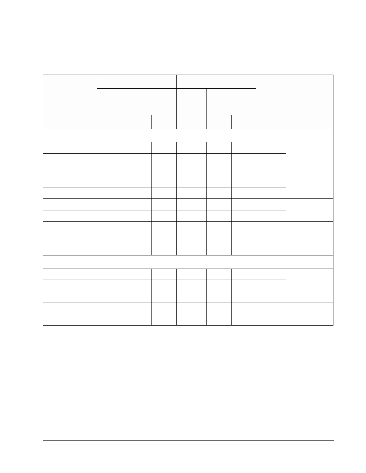
Table 2-1 Rating Table for ACS 502 and ACS 504, 440 – 500 VAC,& 525 – 600 VAC
Constant Torque Variable Torque
Drive Type
hp
Amps
(Current Rating
of Drive)
I
R
IIN I
hp
Amps
(Current Rating
of Drive)
I
RSQ
INSQ
480 volt units
ACS50X-050-4- 50 65 62 60 77 69 65
ACS50X-075-4- 75 96 87 100 124 111 112
ACS50X-100-4- 100 124 113 125 156 141 135
ACS50X-125-4- 125 156 143 150 180 159 164
ACS50X-150-4- 150 180 161 200 240 214 200
ACS50X-200-4- 200 240 218 250 302 269 240
I
N
Dimension
Referenc e
R6ACS50X-060-4- 60 77 71 75 96 87 84
R7
R8
ACS50X-250-4- 250 302 273 300 361 328 300
R9ACS50X-300-4- 300 361 333 350 414 376 365
ACS50X-350-4- 300 361 333 400 460 418 365
600 volt units
ACS50X-060-6- 60 62 54 75 77 67 77
ACS50X-075-6- 75 77 67 100 99 87 77
ACS50X-100-6- 100 99 87 125 125 110 99 R7
ACS50X-125-6- 125 125 110 150 144 126 125 R8
ACS50X-150-6- 150 144 126 200 192 168 172 R9
R6
ACS 502 Installation & Start -up Ma nual 2-3

Chapter 2 – Overview of the ACS 502/504
Table 2-2 shows the definitions for symbols used in this manual.
Table 2-2 Symbol Definitio ns
Symbol Definition
V
I
I
P
I
I
P
I
IN
IN
R
R
INSQ
RSQ
RSQ
N
Rated supply voltage [V]. The actual voltage is set by a parameter.
Approximate input current (rms) when shaft power is PR, line voltage is 480 V, and the motor is a standard NEMA
motor [Amps].
Rated output current in constant torque applicati o ns [Amps] .
Maximum motor nominal shaft power in constant torque applications for 2-, 4-, and 6-pole standard motors [hp].
Approximate input current when shaft power is P
motor. This is the maximum thermal input current [Amps].
Rated output current in squared torque applic ati ons [Amps ].
Maximum motor nominal shaft power in squared torque applications for 2-, 4-, and 6-pole standard motors [hp].
The output current on which the drive’s internal trips and settings are based [Amps].
ACS 502 Control
Identification
, line voltage is 480 V and the motor is a standard NEMA
RSQ
The numbers and letters in the last seven spaces of the A CS 502 Mo del
Number stand for the specific options included with your drive. Locate the
Control Nameplate on the right side of the enclosure or inside the door of the
ACS 502 and use Figure 2-2 to verify the options included with your drive.
The first part of the part number is derived from Figure 2-1 by removing the
letters AC in the first two places and the dashes (-).
2-4 ACS 502 Installation & Start-up Manual
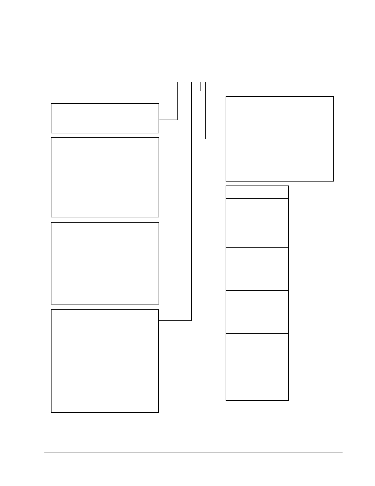
Figure 2-2 Nameplate Codes
NEMA Type Enclosure
2=NEMA 1
3=NEMA 1 with Air Filters
5=NEMA 12
Control
A=Hand-Off-Auto Switch incl. 115 V
Control Transformer
B=Hand-Off-Auto Switch & Speed Pot
incl. 115 V Control Transformer
C=115 VAC Control Transformer
& Terminal Board
1=Internal Brake Chopper
M=A+1
N=B+1
P=C+1
0=None
Input Options
A=Door Interlocked Disconnect Switch
B=Door Interlocked Circuit Breaker
C=Disconnect w/3% Line Reactor
D=Circuit Breaker w/3% Line Reactor
E=Input Terminal Block w/3% Line
Reactor
F=Disconnect w/5% Line Reactor
G=Circuit Breaker w/5% Line Reactor
H=Input Terminal Block w/5% Line
Reactor
0=Extended Enclosure w/Input
Terminal Block
Bypass
A=Manual Bypass
B=Manual Bypass w/Service Switch
C=Automatic Bypass
D=Automatic Bypass w/Service Switch
E=Manual Bypass, Mechanically
Interlocked
F=Manual Bypass w/Service Switch,
Mechanically Interlocked
G=Automatic Bypass, Mechanically
Interlocked
H=Automatic Bypass w/Service
Switch, Mechanically Interlocked
0=None
ACS502-075-4-00P2
S502075400P2
Chapter 2 – Overview of the ACS 502/504
Meters
A=Analog Voltmeter
B=Analog Speed Meter
Y=Ammeter (Sized to unit)
Z=Two Ammeters (Sized to MOL’s)
1=A+B
2=A+Y
3=A+Z
4=B+Y
5=B+Z
6=A+B+Y
7=A+B+Z
0=None
MOL
ACS 502
HP*
A=29.3 to 32.0
25
B=32.1 to 34.9
C=35.0 to 37.8
30
D=37.9 to 41.7
E=41.8 to 45.9
F=46.0 to 49.0
40
G=49.1 to 54.2
H=54.3 to 60.0
J=57.1 to 62.8
50
K=62.9 to 69.1
L=69.2 to 75.0
M=75.1 to 83.3
60
N=83.4 to 86.9
P=87.0 to 92.9
75
Q=93.0 to 100
R=98 to 107.9
S=108 to 113.9
100
T=114 to 125.9
U=126 to 138.9
V=139 to 153
125
W=154 to 163
150
X=164 to 180
Y=175 to 194
Z=195 to 220
200
2=221 to 247
3=248 to 276
4=277 to 307
250
5=308 to 345
6=346 to 381
300
350
7=382 to 420
8=421 to 465
0=None
* Horsepowers listed are estimated only.
MOL’s MUST be sized for the specific motor.
ACS 502 Installation & Start -up Ma nual 2-5

Chapter 2 – Overview of the ACS 502/504
General Information
About Your ACS 502/504
Functional Description
Power-on sequence
When line voltage is switched on, the capacitor bank is charged first via the
charging circuit. The charging takes less than one second. During this time,
the thyristors on the rectifier bridge are not conducting.
GENERAL WARNING! The maximum permissible number of chargings in
one minute is four. If the DC bus is charged more often, the charging resistor
may fail due to excess heat. Therefore, it is recommended that you do not use
the input power switching on and off as a Start/Stop command.
The power supply of the ACS 504 comes from the capacitor bank. The power
supply turns on when the voltage on the capacitors has reached about
300 VDC. Subsequen tly, the Control Interface Card, Motor Control Card an d
Main Circuit Interface Car d are energized.
When the DC-voltage has reached 80% of its nominal value, the
microprocessor on the Motor Control Card energizes the Input Protection
Card. The thyristors are gated fully conducting and the thyristor-diode
rectifier behaves like a normal 6-pulse diode bridge.
Control
Power section
The cooling fan turns on at initial power-on. To prolong the useful life of the
fan bearings, the fan is automatically turned off after one minute, unless:
• The drive has a RU N command, or
• Heatsink temperature is above 113°F (45°C).
In normal duty the drive follows commands and reference s either from the
keypad or the terminal block on the Control Interface Card. The control signal
source selection and the way the drive interprets these signals are configured
by parameters.
Power flow through the drive in normal duty is from AC-input line through
the rectifier bridge to the DC-filter capacitors which sustain a constant DCvoltage. The nominal value for this voltage is 1.35 x V
.
IN
The Inverter consists of six power semiconductor switches whose operati on is
controlled by the Motor Control Card via the Main Circuit Interface Card.
Turning these switches on and off in a certain sequence is called modulation.
The modulation frequency in the ACS 504 is about 3 kHz at maximum and
cannot be altered.
The potential at any terminal U
, V2, W2 (T1, T2, T3) of the inverter can only
2
be high or low. The modulat ion determines which one. At any instant, the line
to line output voltage is either 0 V when t he switches in these phases are i n the
same position or ± 1.35 x VIN when the corresponding switches are in
different positions.
2-6 ACS 502 Installation & Start-up Manual

Chapter 2 – Overview of the ACS 502/504
The output voltage waveform is a p ulse-train . The widths of the puls es depend
on the modulation. The purpose of the modulation is to create the fundamental
voltage wave (its amplitude and frequency), e.g., according to the law
V
/ f
out
= constant (V/Hz).
out
The distortion of the output voltage from the sinusoidal fundamental creates
corresponding harmonics in the motor current. However, since the motor is
highly inductive and the modulation frequency is relatively high, the current
waveform is nearly sinusoidal.
Protective features
Power-off sequence
Should something adverse happen during power-up or normal duty, the drive
incorporates the following features to protect itself:
• Internal overtemperature (warning and trip)
• Overcurrent (two current limits and trip)
• Input line phase loss / unbalance (trip)
• Overvoltage (trip at 130% nominal DC-voltage)
• Undervoltage (trip at 60% nominal DC-voltage)
• Starting at overvoltage (>117% of nominal DC-voltage inhibits start)
• Ground fault (>2.5 amps)
In addition, the drive identifies various internal and external hardware faults
and displays a diagnostic message.
The ACS 504 also has a variety of protective features for the motor, such as:
• Stall (warning and trip)
• Overload (warning and trip)
• Underload (warning and trip)
A high voltage remains on the capacitor bank after the line voltage is
disconnected. This voltage is discharged through discharging resistors (R11)
within five minutes. Always use a voltage measuremen t to determine that the
voltage has dropped before performing any service or making main circuit
connections. Measure between terminals UD C+ and UDC-; also measure
between UDC+ and chassis ground. The meter must be capable of
withstanding 1000 VDC.
ACS 502 Installation & Start -up Ma nual 2-7
Chapter 2 – Overview of the ACS 502/504
Control Panel Operation
Control Pan el D isplay
The Contro l Pane l, located on top of the Control Interface Card, has a 2x20
character alphanumeric LCD and a keypad.
The operation information, parameters and fault indications are displayed in
nine languages: English, German, Italian, Spanish, Dutch, French, Danish,
Finnish, and Swedish. The language selection is made in Start-up Data,
Parameter A (Lan guage).
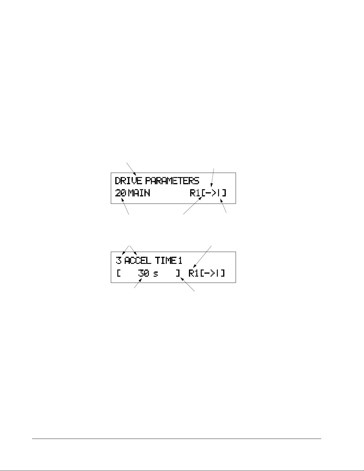
Figure 2-3 shows control panel display indications.
Figure 2-3 Control Panel Displays
Main Name
Main Number
Parameter Number
and Name
Control Location
[ ] = Keypad Control
No Brackets = External
Rotation Direction
→ = Forward
← = Reverse
Run Status
I = Run
O = Stop
Active Reference
R1 = Ref 1
Parameter Value
Mode Indication
[ ] = Setting Mode
No Brackets = Display Mode
2-8 ACS 502 Installation & Start-up Manual

Chapter 2 – Overview of the ACS 502/504
Contr ol Panel Keys
Table 2-3 illustrates each Control Panel Key, how the keys are used in this
manual's text, and describes the function of each key.
Table 2-3 Control Panel Ke ys
Control Panel
Key
Text Reference Function
[ * ] Selects the Setting mode and saves the selected
parameter value.
[Right Arrow]
[Left Arrow]
[Up Arrow]
[Down Arrow]
Steps between levels.
Selects between O peratin g Data, Main, Group,
and Parameter levels.
and
In Setting Mode, returns to the Display mode
without changing the Parameter value.
Steps through choices within a level.
In Display mode, selects the next/previous Main,
Group, or Parameter.
and
In Setting mode, increases/decreases parameter
value.
[Fwd/Rev] Changes the rotation direction in Keypad control
(refer to parameter 10.1.3).
[Start/Stop] Starts and stops the motor in Keypad control.
Resets faults, warnings, and supervision
indications.
Note: To accelerate the change of parameter value, press and hold the
[Up Arrow] or [Down Arrow] button.
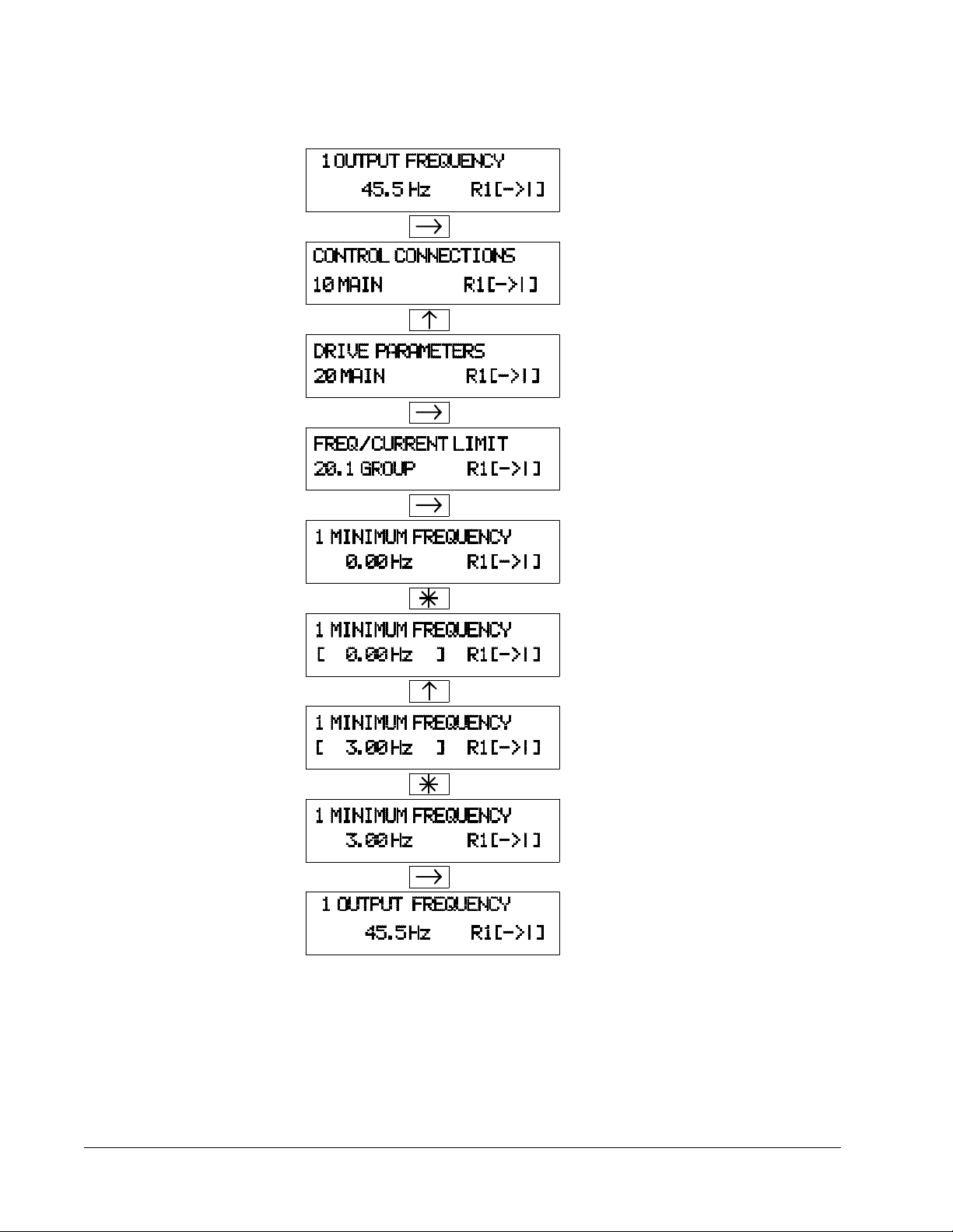
Figure 2-4 shows how to set Parameter 20.1.1 (Minimum Frequency) to 3 Hz.
ACS 502 Installation & Start -up Ma nual 2-9
Chapter 2 – Overview of the ACS 502/504
Figure 2-4 Parameter Settings
Indent to Main level.
Select the required Main.
Indent to Group level. Select the required
Group by [Up Arrow] and [Down Arrow] key s.
Indent to Parameter level. Select the required
Parameter by [U p Arrow] and [Down Arrow]
key.
Change to Setting mode. Brackets indicate that
the parameter value now can be changed.
Set the parameter value. If you want to cancel the
change and return to Display mode, press [Right
Arrow] or [Left Arrow], otherwise
Save the selected value to parameter memor y.
Brackets disappear indicating that the param eter
value is stored in memory.
Return to Operating Data parameter 1 (Output
Frequency).
2-10 ACS 502 Installation & Start-up Manual

Chapter 2 – Overview of the ACS 502/504
Adjusting Display
Contrast
Application Macros Overview
The contrast of the LCD can be adjusted for optimal viewing. This can be
done when the display is in the Main or Group level.
To adjust contrast, press and hold [ * ] and then press [Up Arrow] or
[Down Arrow].
You may need to adjust the display contrast if the ACS 502 has been installed
in a location with high ambient temperatures. The factory default setting is
optimum for a n ambient temperature between 59°F and 86°F (15°C and
30°C).
Application macros are complete sets of default parameter settings for some
typical applications. This allows all of the parameter s to be set with the touch
of a button.
When you select an Application macro, the parameters listed in the ACS 500
Adjustable Frequency AC Drives 2 to 350 HP Programming Manual
Including Application Macros are set to a value suitable for a particular
application. The parameters which are not included in the Application macro
retain the factory settings. If you must adjust the parameter values, refer to the
instructions in the ACS 500 Adjustable Frequency AC Drives 2 to 350 HP
Programming Manual Including Application Macros.
Hardware Description
Inverter Module
The ACS 504 chassis units consist of a Control Unit and an Inverter Module.
These communicate via a multi-conductor cable.
The ACS 502 series drives consist of an ACS 504 chassis unit mounted in an
enclosure.
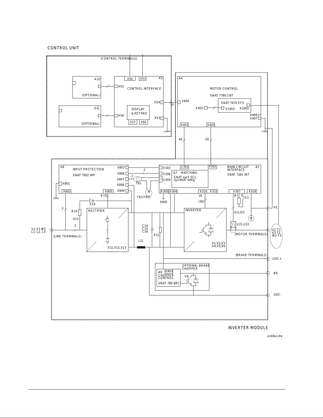
Figure 2-5 shows the components of the ACS 504. Table 2-4 gives the
description of the components.
ACS 502 Installation & Start -up Ma nual 2 -1 1
Chapter 2 – Overview of the ACS 502/504
AAAA
AAAA
AAAA
AAAA
AAAA
AAAA
AAAA
AAAA
AAAA
AAAA
AAAA
AAAA
AAAA
AAAA
AAAA
AAAA
AAAA
AAAA
AAAA
AAAA
AAAA
AAAA
AAAA
AAAA
AAAA
AAAA
Figure 2-5 ACS 504 Components
CONTROL UNIT
(CONTROL TERMINALS)
U1,V1,W1
L1, L2, L3
A8
INPUT PROTECTION
SNAT 7902 INP
X801
X802
3
R14
(U1)
3
(LINE TERMINALS)
A10
(OPTIONAL)
A11
(OPTIONAL)
V14
RECTIFIER
6 (3)
X805
X55
X56
X803
X806
X807
X808
X809
V11,V12,V13
X51
X50
CONTROL INTERFACE
X54
DISPLAY
& KEYPAD
X60
X53
X57
2
2
T61
M
Y61(Y62)
C14
C15
C16
R11
L11
A5
A4
MOTOR CONTROL
SNAT 7780 CNT
X404
10
X403
SNAT 7670 EFS
X1003
X1003
X401 X402
40 20
X303
X306
X309
X301
A7
MATCHING
SNAT xyz5 SCL
xyz=kVA rating
X305 X304 X307 X318
X905
INVERTER
X302
X310...X315
(30)
MAIN CIRCUIT
INTERFACE
SNAT 7261 INT
t
R718
S1
IU2,IV2
I
U21,U22
I
(MOTOR TERMINALS)
V1,V2,V3
V4,V5,V6
(BRAKE TERMINALS)
OPTIONAL BRAKE
X905
A9
CHOPPER
CONTROL
CHOPPER
V8
SNAT 780 BRC
X406
X407
A3
PE
U2 T1
V2 T2
W2 T3
UDC+
BR
INVERTER MODULE
2-12 ACS 502 Installation & Start-up Manual
UDC-
acsblkus.drw

Chapter 2 – Overview of the ACS 502/504
Table 2-4 ACS 504 Inverter Module Component Description
Component Component Description
R14, V14 Pre -charging circuit for limit ing the current surge when power is first applied.
V11, V12, V13 Rectifier bridge. This is a half-controlle d thyristor bridge . During pre-charging, the thyristors are blocked and
thereafter they are gated fully conduct ing.
A8 Input Protection Card SNAT 7902 INP. This contains gate trig ger circuits for the rectif ier thyristors , capac itors ,
and varistors to protect the bridge. It also contains fus es to protect the fan.
L11, C14 – C16,
R11
V1
– V6 Inverter insulated gate bipolar transistors (IGBT) and clamp circuits.
A3 Main Circuit Inte rf ace Card SNAT 7261 INT. This card contains the power supply, transis tor gate trigger cir-
A7 Small card on top of SNA T 7261 INT. This contains the power range programming information for the ACS 504
U21, U22 Current transducers for motor current measurement.
Y61, Y62 Cooling fan(s) and associate d trans for mer (T 61). Note: the trans form er connection must be made according to
R7 Me asure s the temper atur e of the heatsin k. The thermostat (S1) provides thermal protec tion for th ose parts that
(V8, A9) Optional braking chopper: transistor and its control card SNAT 780 BRC. The braking resistor is outside the
A5 Control Interface Card contains the display, keypad, and terminal block X50 fo r control wiring. RS485 terminals
A4 Motor Control Card SNAT 777 CNT.
(A10, A11) Option cards.
DC-filter choke and capacitors with discharge resistors. Note: In 600 volt units, L11 (DC-filter choke) is omitted
and replaced by a three-phase AC choke at L1, L2, and L3. 600 volt units also have a three-phase AC output
choke at T1, T2, and T3.
cuits, and DC-voltage and motor current measurement circuits.
hardware.
(SNAT xyz5 SCL, where xyz is the kVA rating of the Module).
the actual supply voltage. Supply voltage is set to 500 V at the factor y.
are not covered by R7.
module.
X51, X52, and the programming jumpers for analog inputs are on this card.
GENERAL WARNING! The ACS 504 Inverter Module does not include
fuses within the module. Fuses are supplied for separate mounting.
ACS 502 Installation & Start -up Ma nual 2 -1 3
Chapter 2 – Overview of the ACS 502/504
WARNING! Parts within the Inverter Module are at main circuit potential.
The printed circuit boards within the Control Unit are grounded. The signal
isolation takes place in the Inverter Module.
Features
and Functions
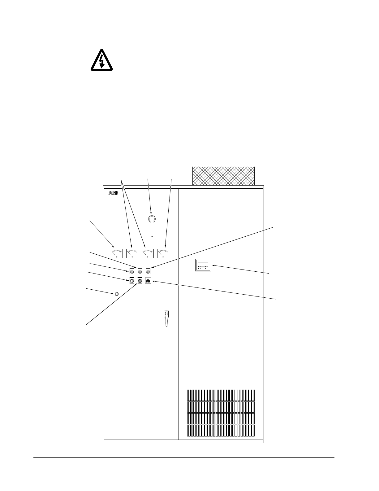
Figure 2-6 ACS 502 Front Door
Ammeters
Voltmeter
Bypass
Pilot Light
Normal
Pilot Light
Bypass
Switch
MOL
Reset
VM AM1 AM2 SPM
RESET
The ACS 502 is an enclosed, floor-standing adjustable frequency AC drive.
Depending on the options chosen, the ACS 502 provides motor overload
protection, disconnect switch or circuit breaker, bypass, analog meters,
indicator lights, and external control connections.
Figure 2-6 shows the door of the ACS 502 and indicates all possible options.
Your drive may not look exactly like the illustration.
ABB Drive s
OPL
SS2
W Y
Disconnect
handle
BPL FPL
POTSS1
Speed
Meter
Ext. Fault
Pilot Light
R
Keypad/Digital
Display
Speed
Pot
HOA
Switch
2-14 ACS 502 Installation & Start-up Manual
 Loading...