

Page 1
User Interface Guide
ACS380
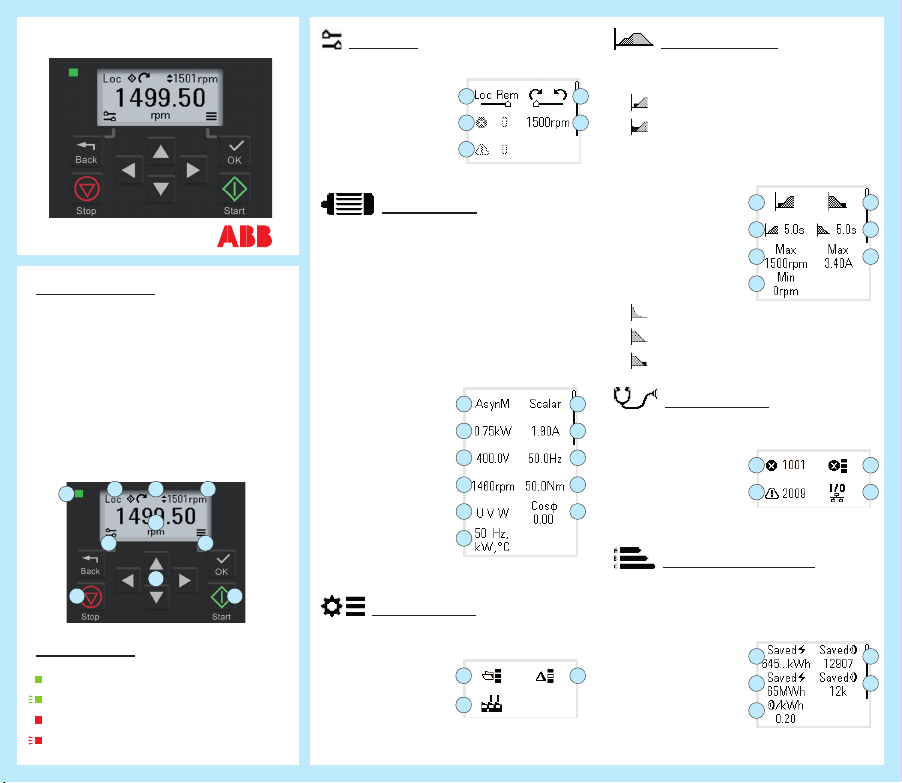
Control panel
1. Status light
2. Local /
remote
3. Status icons
4. Reference
value
5. Actual value
6. Back /
Options
1
6
7
Status light
green, steady: OK
green, blinking: Warning
red, steady: Fault
red, blinking: Fault, turn power off
to reset
7. Stop
8. Edit value /
Move in
menus
9. OK / Select /
Save / Menu
10. Start
2 43
5
9
8
10
Options
1. Control location
2. Active fault
3. Active warnings
4. Forward /
Reverse
1 4
2 5
3
5. Reference
Motor data
1. Motor type
• AsynM
• PMSM
• SynRM
2. Nominal
power
3. Nominal
voltage
4. Nominal
speed
5. Phase order
Change
direction without
reconnecting
motor cables
6. Unit
selection
7. Control
mode
Scalar or vector
8. Nominal
current
9. Nominal
frequency
10. Nominal
torque
11. Nominal
cos phi
1 7
2
3
4
5
6
Parameters
Direct access to all functions (advanced)
1. Complete list
2. Reset to
factory
defaults
3. Modied only
1
2
1. Start mode
2. Acceleration
3. Max.
4. Min. allowed
5. Stop mode
8
1. Active fault
2. Active
9
10
3. Fault history
4. Connection
11
1. Saved
2. Saved
3
3. Cost per
4. Saved
Motor control
Const time
Automatic
time
allowed
speed
speed
Coast
Ramp
DC Hold
Diagnostics
warnings
status
Energy efciency
energy in
kWh
energy in
MWh
kWh
money
6. Deceleration
time
7. Max.
allowed
current
1 5
2 6
3 7
4
1 3
2 4
5. Saved
money
x1000
1 4
2 5
3
Page 2
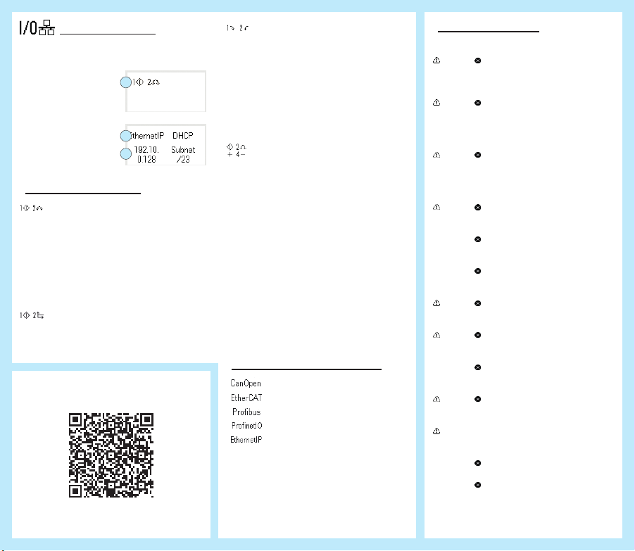
Control macros
The menu content depends on the installed
extension module.
I/O control:
1
1. I/O control
macro
Fieldbus control:
1. Protocol
2. Address
1
2
settings
I/O control macros
Standard (2-wire)
AI1: Reference
DI1: Start / Stop
DI2: Forward / Reverse
DI3: Constant speed sel1
DI4: Constant speed sel2
DIO1: Ramp pair selection
DIO2: Ready run
ABB limited 2-wire
Integrated panel: Reference
DI1: Start / Stop
DI2: Constant speed sel1
For the full manual, go to:
3AXD50000022224 Rev. B EN
Alternate
AI1: Reference
DI1: Start forward
DI2: Start reverse
(if DI1 = DI2, stop)
DI3: Constant speed sel1
DI4: Constant speed sel2
DIO1: Ramp pair selection
DIO2: Ready run
Motor potentiometer
DI1: Start / Stop
DI2: Forward / Reverse
DI3: Reference up
DI4: Reference down
DIO1: Constant sel1
DIO2: Ready run
PID
PID
AI1: Setpoint
AI2: Feedback
DI1: Start / Stop
DI2: Constant setpoint 1
DI3: Constant setpoint 2
DI4: Constant speed 1
DIO1: Ramp pair selection
DIO2: Ready run
Fieldbus control macros
CANopen
EtherCAT
PROFIBUS
Pronet
Ethernet/IP
Modbus
Modbus TCP
TCP
Modbus
Modbus RTU
RTU
Start/stop/reference from the eldbus
DI1: Fault reset
DI2: Not congured
Warnings/Faults
Warning Fault Description
A2A1 2281 Warning: Current calibration
A2B1 2310 Overcurrent. The output
A2B3 2330 Earth leakage. A load
A2B4 2340 Short circuit. There is a
A3A1 3210 DC link overvoltage. There
A3A2 3220 DC link undervoltage. There
A5A0 5091 Safe torque off. The Safe
AFF6 Identication run. The motor
is done at the next start.
Fault: Output phase current
measurement fault
current is more than the
internal limit. This can be
caused by an earth fault or
phase loss.
unbalance that is typically
caused by an earth fault
in the motor or the motor
cable.
short circuit in the motor or
the motor cable.
3130 Input phase loss. The
intermediate DC circuit
voltage oscillates.
3181 Cross connection. The
input and motor cable
connections are incorrect.
is an overvoltage in the
intermediate DC circuit.
is an undervoltage in the
intermediate DC circuit.
3381 Output phase loss. All three
phases are not connected
to the motor.
torque off (STO) function
is on.
ID run occurs at the next
start.
FA81 Safe torque off 1. The Safe
torque off circuit 1 is broken.
FA82 Safe torque off 2. The Safe
torque off circuit 2 is broken.
 Loading...