

Page 1
—
ABB MACHINERY DRIVES
ACS380 machinery control program
Firmware manual
Page 2

—
List of related manuals
Drive hardware manuals and guides Code (English)
Drive/converter/inverter safety instructions
ACS380 Hardware manual 3AXD50000029274
Drive firmware manuals and guides
ACS380 Firmware manual 3AXD50000029275
ACS380 Quick installation and start-up guide 3AXD50000018553
ACS380 User interface guide 3AXD50000022224
Option manuals and guides
ACS-AP-x Assistant control panels user’s manual 3AUA0000085685
ACS-BP-S Basic control panel user’s manual 3AXD50000032527
FCAN-01 CANopen adapter module user’s manual 3AFE68615500
FECA-01 EtherCAT adapter module user’s manual 3AUA0000068940
FENA-01/-11/-21 Ethernet adapter module user’s
manual
FPBA-01 PROFIBUS DP adapter module user’s manual 3AFE68573271
FEPL-02 Ethernet POWERLINK adapter module user’s
manual
Tool and maintenance manuals and guides
Drive composer PC tool user’s manual 3AUA0000094606
Converter module capacitor reforming instructions 38FE64059629
Adaptive Programming Application guide 3AXD50000028574
NETA-21 remote monitoring tool user’s manual 3AUA0000096939
NETA-21 remote monitoring tool installation and start-
up guide
3AXD50000037978
3AUA0000093568
3AUA0000123527
3AUA0000096881
You can find manuals and other product documents in PDF format on the
Internet. See section Document library on the Internet on the inside of the
back cover. For manuals not available in the Document library, contact your
local ABB representative.
The code below opens an online listing of the manuals applicable to the
product:
Page 3

Firmware manual
ACS380 machinery control program
Table of contents
3. Start-up, ID run and use
2018 ABB Oy. All Rights Reserved.
3AXD50000029275 Rev E
EN
EFFECTIVE: 2018-05-05
Page 4

Page 5

Table of contents 5
Table of contents
1. Introduction to the manual
Contents . . . . . . . . . . . . . . . . . . . . . . . . . . . . . . . . . . . . . . . . . . . . . . . . . . . . . . . . . . . . . . . . . 11
Applicability . . . . . . . . . . . . . . . . . . . . . . . . . . . . . . . . . . . . . . . . . . . . . . . . . . . . . . . . . . . . . . . 11
Safety instructions . . . . . . . . . . . . . . . . . . . . . . . . . . . . . . . . . . . . . . . . . . . . . . . . . . . . . . . . . . 11
Target audience . . . . . . . . . . . . . . . . . . . . . . . . . . . . . . . . . . . . . . . . . . . . . . . . . . . . . . . . . . . . 12
Purpose of the manual . . . . . . . . . . . . . . . . . . . . . . . . . . . . . . . . . . . . . . . . . . . . . . . . . . . . . . 12
Contents of the manual . . . . . . . . . . . . . . . . . . . . . . . . . . . . . . . . . . . . . . . . . . . . . . . . . . . . . . 12
Terms and abbreviations . . . . . . . . . . . . . . . . . . . . . . . . . . . . . . . . . . . . . . . . . . . . . . . . . . . . . 13
Related manuals . . . . . . . . . . . . . . . . . . . . . . . . . . . . . . . . . . . . . . . . . . . . . . . . . . . . . . . . . . . 15
Cybersecurity disclaimer . . . . . . . . . . . . . . . . . . . . . . . . . . . . . . . . . . . . . . . . . . . . . . . . . . . . . 15
2. Control panel
Contents . . . . . . . . . . . . . . . . . . . . . . . . . . . . . . . . . . . . . . . . . . . . . . . . . . . . . . . . . . . . . . . . . 17
Control panel . . . . . . . . . . . . . . . . . . . . . . . . . . . . . . . . . . . . . . . . . . . . . . . . . . . . . . . . . . . . . . 17
Home view and Message view . . . . . . . . . . . . . . . . . . . . . . . . . . . . . . . . . . . . . . . . . . . . . . . . 18
Options menu and Main menu . . . . . . . . . . . . . . . . . . . . . . . . . . . . . . . . . . . . . . . . . . . . . . . . 19
Options menu . . . . . . . . . . . . . . . . . . . . . . . . . . . . . . . . . . . . . . . . . . . . . . . . . . . . . . . . . . 19
Main menu . . . . . . . . . . . . . . . . . . . . . . . . . . . . . . . . . . . . . . . . . . . . . . . . . . . . . . . . . . . . 19
3. Start-up, ID run and use
Contents . . . . . . . . . . . . . . . . . . . . . . . . . . . . . . . . . . . . . . . . . . . . . . . . . . . . . . . . . . . . . . . . . 23
Start up the drive . . . . . . . . . . . . . . . . . . . . . . . . . . . . . . . . . . . . . . . . . . . . . . . . . . . . . . . . . . . 23
Do the identification (ID) run . . . . . . . . . . . . . . . . . . . . . . . . . . . . . . . . . . . . . . . . . . . . . . . . . . 25
Background information . . . . . . . . . . . . . . . . . . . . . . . . . . . . . . . . . . . . . . . . . . . . . . . . . . 25
ID run steps . . . . . . . . . . . . . . . . . . . . . . . . . . . . . . . . . . . . . . . . . . . . . . . . . . . . . . . . . . . . 25
Start and stop the drive . . . . . . . . . . . . . . . . . . . . . . . . . . . . . . . . . . . . . . . . . . . . . . . . . . . . . . 27
Change the rotation direction . . . . . . . . . . . . . . . . . . . . . . . . . . . . . . . . . . . . . . . . . . . . . . . . . 27
Set the speed or frequency reference . . . . . . . . . . . . . . . . . . . . . . . . . . . . . . . . . . . . . . . . . . . 27
Set the drive parameters . . . . . . . . . . . . . . . . . . . . . . . . . . . . . . . . . . . . . . . . . . . . . . . . . . . . . 28
Open Diagnostics . . . . . . . . . . . . . . . . . . . . . . . . . . . . . . . . . . . . . . . . . . . . . . . . . . . . . . . . . . 28
Change the units . . . . . . . . . . . . . . . . . . . . . . . . . . . . . . . . . . . . . . . . . . . . . . . . . . . . . . . . . . . 29
Safety
4. Control macros
Contents . . . . . . . . . . . . . . . . . . . . . . . . . . . . . . . . . . . . . . . . . . . . . . . . . . . . . . . . . . . . . . . . . 31
ABB standard macro . . . . . . . . . . . . . . . . . . . . . . . . . . . . . . . . . . . . . . . . . . . . . . . . . . . . . . . . 32
Default control connections for the ABB standard macro . . . . . . . . . . . . . . . . . . . . . . . . . 33
ABB limited macro . . . . . . . . . . . . . . . . . . . . . . . . . . . . . . . . . . . . . . . . . . . . . . . . . . . . . . . . . . 35
Default control connections for the ABB limited macro . . . . . . . . . . . . . . . . . . . . . . . . . . . 35
Fieldbus control macro . . . . . . . . . . . . . . . . . . . . . . . . . . . . . . . . . . . . . . . . . . . . . . . . . . . . . . 36
Default control connections for the Fieldbus macro . . . . . . . . . . . . . . . . . . . . . . . . . . . . . 36
Alternate macro . . . . . . . . . . . . . . . . . . . . . . . . . . . . . . . . . . . . . . . . . . . . . . . . . . . . . . . . . . . . 38
Default control connections for the Alternate macro . . . . . . . . . . . . . . . . . . . . . . . . . . . . . 39
Page 6

6 Table of contents
Motor potentiometer macro . . . . . . . . . . . . . . . . . . . . . . . . . . . . . . . . . . . . . . . . . . . . . . . . . . 41
Default control connections for the Motor potentiometer macro . . . . . . . . . . . . . . . . . . . 42
PID control macro . . . . . . . . . . . . . . . . . . . . . . . . . . . . . . . . . . . . . . . . . . . . . . . . . . . . . . . . . . 44
Default control connections for PID control macro . . . . . . . . . . . . . . . . . . . . . . . . . . . . . . 44
Modbus macro . . . . . . . . . . . . . . . . . . . . . . . . . . . . . . . . . . . . . . . . . . . . . . . . . . . . . . . . . . . . 46
Default control connections for the Modbus macro . . . . . . . . . . . . . . . . . . . . . . . . . . . . . 47
Parameter default values for different macros . . . . . . . . . . . . . . . . . . . . . . . . . . . . . . . . . . . . 49
5. Program features
Contents . . . . . . . . . . . . . . . . . . . . . . . . . . . . . . . . . . . . . . . . . . . . . . . . . . . . . . . . . . . . . . . . . 51
Local and external control locations . . . . . . . . . . . . . . . . . . . . . . . . . . . . . . . . . . . . . . . . . . . . 52
Local control . . . . . . . . . . . . . . . . . . . . . . . . . . . . . . . . . . . . . . . . . . . . . . . . . . . . . . . . . . . 52
External control . . . . . . . . . . . . . . . . . . . . . . . . . . . . . . . . . . . . . . . . . . . . . . . . . . . . . . . . 53
Operating modes and motor control modes . . . . . . . . . . . . . . . . . . . . . . . . . . . . . . . . . . . . . . 54
Overview diagram of control hierarchy . . . . . . . . . . . . . . . . . . . . . . . . . . . . . . . . . . . . . . . 54
Speed control mode . . . . . . . . . . . . . . . . . . . . . . . . . . . . . . . . . . . . . . . . . . . . . . . . . . . . . 56
Torque control mode . . . . . . . . . . . . . . . . . . . . . . . . . . . . . . . . . . . . . . . . . . . . . . . . . . . . 56
Frequency control mode . . . . . . . . . . . . . . . . . . . . . . . . . . . . . . . . . . . . . . . . . . . . . . . . . 56
Special control modes . . . . . . . . . . . . . . . . . . . . . . . . . . . . . . . . . . . . . . . . . . . . . . . . . . . 56
Settings . . . . . . . . . . . . . . . . . . . . . . . . . . . . . . . . . . . . . . . . . . . . . . . . . . . . . . . . . . . . . . 57
Autophasing . . . . . . . . . . . . . . . . . . . . . . . . . . . . . . . . . . . . . . . . . . . . . . . . . . . . . . . . . . . 57
Drive configuration and programming . . . . . . . . . . . . . . . . . . . . . . . . . . . . . . . . . . . . . . . . . . 60
Programming via parameters . . . . . . . . . . . . . . . . . . . . . . . . . . . . . . . . . . . . . . . . . . . . . . 60
Adaptive programming . . . . . . . . . . . . . . . . . . . . . . . . . . . . . . . . . . . . . . . . . . . . . . . . . . . 61
Control interfaces . . . . . . . . . . . . . . . . . . . . . . . . . . . . . . . . . . . . . . . . . . . . . . . . . . . . . . . . . . 64
Programmable analog inputs . . . . . . . . . . . . . . . . . . . . . . . . . . . . . . . . . . . . . . . . . . . . . . 64
Programmable analog outputs . . . . . . . . . . . . . . . . . . . . . . . . . . . . . . . . . . . . . . . . . . . . . 64
Programmable digital inputs and outputs . . . . . . . . . . . . . . . . . . . . . . . . . . . . . . . . . . . . . 64
Programmable relay outputs . . . . . . . . . . . . . . . . . . . . . . . . . . . . . . . . . . . . . . . . . . . . . . 65
Programmable I/O extensions . . . . . . . . . . . . . . . . . . . . . . . . . . . . . . . . . . . . . . . . . . . . . 65
Fieldbus control . . . . . . . . . . . . . . . . . . . . . . . . . . . . . . . . . . . . . . . . . . . . . . . . . . . . . . . . 65
Motor control . . . . . . . . . . . . . . . . . . . . . . . . . . . . . . . . . . . . . . . . . . . . . . . . . . . . . . . . . . . . . 66
Motor types . . . . . . . . . . . . . . . . . . . . . . . . . . . . . . . . . . . . . . . . . . . . . . . . . . . . . . . . . . . 66
Motor identification . . . . . . . . . . . . . . . . . . . . . . . . . . . . . . . . . . . . . . . . . . . . . . . . . . . . . . 66
Power loss ride-through . . . . . . . . . . . . . . . . . . . . . . . . . . . . . . . . . . . . . . . . . . . . . . . . . . 66
Vector control . . . . . . . . . . . . . . . . . . . . . . . . . . . . . . . . . . . . . . . . . . . . . . . . . . . . . . . . . . 66
Reference ramping . . . . . . . . . . . . . . . . . . . . . . . . . . . . . . . . . . . . . . . . . . . . . . . . . . . . . . 67
Constant speeds/frequencies . . . . . . . . . . . . . . . . . . . . . . . . . . . . . . . . . . . . . . . . . . . . . . 68
Critical speeds/frequencies . . . . . . . . . . . . . . . . . . . . . . . . . . . . . . . . . . . . . . . . . . . . . . . 68
Rush control . . . . . . . . . . . . . . . . . . . . . . . . . . . . . . . . . . . . . . . . . . . . . . . . . . . . . . . . . . . 70
Encoder echo support . . . . . . . . . . . . . . . . . . . . . . . . . . . . . . . . . . . . . . . . . . . . . . . . . . . 70
Jogging . . . . . . . . . . . . . . . . . . . . . . . . . . . . . . . . . . . . . . . . . . . . . . . . . . . . . . . . . . . . . . 70
Speed control performance figures . . . . . . . . . . . . . . . . . . . . . . . . . . . . . . . . . . . . . . . . . 73
Torque control performance figures . . . . . . . . . . . . . . . . . . . . . . . . . . . . . . . . . . . . . . . . . 73
Scalar motor control . . . . . . . . . . . . . . . . . . . . . . . . . . . . . . . . . . . . . . . . . . . . . . . . . . . . . 74
User load curve . . . . . . . . . . . . . . . . . . . . . . . . . . . . . . . . . . . . . . . . . . . . . . . . . . . . . . . . 75
U/f ratio . . . . . . . . . . . . . . . . . . . . . . . . . . . . . . . . . . . . . . . . . . . . . . . . . . . . . . . . . . . . . . . 76
Flux braking . . . . . . . . . . . . . . . . . . . . . . . . . . . . . . . . . . . . . . . . . . . . . . . . . . . . . . . . . . . 76
DC magnetization . . . . . . . . . . . . . . . . . . . . . . . . . . . . . . . . . . . . . . . . . . . . . . . . . . . . . . . 77
Energy optimization . . . . . . . . . . . . . . . . . . . . . . . . . . . . . . . . . . . . . . . . . . . . . . . . . . . . . 79
Page 7

Table of contents 7
Switching frequency . . . . . . . . . . . . . . . . . . . . . . . . . . . . . . . . . . . . . . . . . . . . . . . . . . . . . 79
Speed compensated stop . . . . . . . . . . . . . . . . . . . . . . . . . . . . . . . . . . . . . . . . . . . . . . . . . 80
Application control . . . . . . . . . . . . . . . . . . . . . . . . . . . . . . . . . . . . . . . . . . . . . . . . . . . . . . . . . . 81
Control macros . . . . . . . . . . . . . . . . . . . . . . . . . . . . . . . . . . . . . . . . . . . . . . . . . . . . . . . . . 81
Process PID control . . . . . . . . . . . . . . . . . . . . . . . . . . . . . . . . . . . . . . . . . . . . . . . . . . . . . 81
Mechanical brake control . . . . . . . . . . . . . . . . . . . . . . . . . . . . . . . . . . . . . . . . . . . . . . . . . 84
DC voltage control . . . . . . . . . . . . . . . . . . . . . . . . . . . . . . . . . . . . . . . . . . . . . . . . . . . . . . . . . . 90
Overvoltage control . . . . . . . . . . . . . . . . . . . . . . . . . . . . . . . . . . . . . . . . . . . . . . . . . . . . . . 90
Undervoltage control (power loss ride-through) . . . . . . . . . . . . . . . . . . . . . . . . . . . . . . . . 90
Voltage control and trip limits . . . . . . . . . . . . . . . . . . . . . . . . . . . . . . . . . . . . . . . . . . . . . . 91
Settings . . . . . . . . . . . . . . . . . . . . . . . . . . . . . . . . . . . . . . . . . . . . . . . . . . . . . . . . . . . . . . . 92
Brake chopper . . . . . . . . . . . . . . . . . . . . . . . . . . . . . . . . . . . . . . . . . . . . . . . . . . . . . . . . . . 93
Limit to limit control . . . . . . . . . . . . . . . . . . . . . . . . . . . . . . . . . . . . . . . . . . . . . . . . . . . . . . . . . 94
Limit to limit control function . . . . . . . . . . . . . . . . . . . . . . . . . . . . . . . . . . . . . . . . . . . . . . . 95
Limitations . . . . . . . . . . . . . . . . . . . . . . . . . . . . . . . . . . . . . . . . . . . . . . . . . . . . . . . . . . . . . 95
Tips . . . . . . . . . . . . . . . . . . . . . . . . . . . . . . . . . . . . . . . . . . . . . . . . . . . . . . . . . . . . . . . . . . 96
Safety and protections . . . . . . . . . . . . . . . . . . . . . . . . . . . . . . . . . . . . . . . . . . . . . . . . . . . . . . . 97
Fixed/Standard protections . . . . . . . . . . . . . . . . . . . . . . . . . . . . . . . . . . . . . . . . . . . . . . . . 97
Emergency stop . . . . . . . . . . . . . . . . . . . . . . . . . . . . . . . . . . . . . . . . . . . . . . . . . . . . . . . . 97
Motor thermal protection . . . . . . . . . . . . . . . . . . . . . . . . . . . . . . . . . . . . . . . . . . . . . . . . . . 98
Programmable protection functions . . . . . . . . . . . . . . . . . . . . . . . . . . . . . . . . . . . . . . . . 101
Automatic fault resets . . . . . . . . . . . . . . . . . . . . . . . . . . . . . . . . . . . . . . . . . . . . . . . . . . . 103
Diagnostics . . . . . . . . . . . . . . . . . . . . . . . . . . . . . . . . . . . . . . . . . . . . . . . . . . . . . . . . . . . . . . 104
Signal supervision . . . . . . . . . . . . . . . . . . . . . . . . . . . . . . . . . . . . . . . . . . . . . . . . . . . . . . 104
Energy saving calculators . . . . . . . . . . . . . . . . . . . . . . . . . . . . . . . . . . . . . . . . . . . . . . . . 104
Load analyzer . . . . . . . . . . . . . . . . . . . . . . . . . . . . . . . . . . . . . . . . . . . . . . . . . . . . . . . . . 104
Miscellaneous . . . . . . . . . . . . . . . . . . . . . . . . . . . . . . . . . . . . . . . . . . . . . . . . . . . . . . . . . . . . 106
Backup and restore . . . . . . . . . . . . . . . . . . . . . . . . . . . . . . . . . . . . . . . . . . . . . . . . . . . . . 106
User parameter sets . . . . . . . . . . . . . . . . . . . . . . . . . . . . . . . . . . . . . . . . . . . . . . . . . . . . 106
Data storage parameters . . . . . . . . . . . . . . . . . . . . . . . . . . . . . . . . . . . . . . . . . . . . . . . . 107
Parameter checksum calculation . . . . . . . . . . . . . . . . . . . . . . . . . . . . . . . . . . . . . . . . . . 107
Motor potentiometer . . . . . . . . . . . . . . . . . . . . . . . . . . . . . . . . . . . . . . . . . . . . . . . . . . . . 108
User lock . . . . . . . . . . . . . . . . . . . . . . . . . . . . . . . . . . . . . . . . . . . . . . . . . . . . . . . . . . . . . 109
6. Parameters
Contents . . . . . . . . . . . . . . . . . . . . . . . . . . . . . . . . . . . . . . . . . . . . . . . . . . . . . . . . . . . . . . . . 111
Terms and abbreviations . . . . . . . . . . . . . . . . . . . . . . . . . . . . . . . . . . . . . . . . . . . . . . . . . . . . 112
Fieldbus addresses . . . . . . . . . . . . . . . . . . . . . . . . . . . . . . . . . . . . . . . . . . . . . . . . . . . . . . . . 112
Summary of parameter groups . . . . . . . . . . . . . . . . . . . . . . . . . . . . . . . . . . . . . . . . . . . . . . . 113
Parameter listing . . . . . . . . . . . . . . . . . . . . . . . . . . . . . . . . . . . . . . . . . . . . . . . . . . . . . . . . . . 115
01 Actual values . . . . . . . . . . . . . . . . . . . . . . . . . . . . . . . . . . . . . . . . . . . . . . . . . . . . . . . 115
03 Input references . . . . . . . . . . . . . . . . . . . . . . . . . . . . . . . . . . . . . . . . . . . . . . . . . . . . . 118
04 Warnings and faults . . . . . . . . . . . . . . . . . . . . . . . . . . . . . . . . . . . . . . . . . . . . . . . . . . 119
05 Diagnostics . . . . . . . . . . . . . . . . . . . . . . . . . . . . . . . . . . . . . . . . . . . . . . . . . . . . . . . . . 120
06 Control and status words . . . . . . . . . . . . . . . . . . . . . . . . . . . . . . . . . . . . . . . . . . . . . . 123
07 System info . . . . . . . . . . . . . . . . . . . . . . . . . . . . . . . . . . . . . . . . . . . . . . . . . . . . . . . . 128
09 Crane application signals . . . . . . . . . . . . . . . . . . . . . . . . . . . . . . . . . . . . . . . . . . . . . . 130
10 Standard DI, RO . . . . . . . . . . . . . . . . . . . . . . . . . . . . . . . . . . . . . . . . . . . . . . . . . . . . . 131
11 Standard DIO, FI, FO . . . . . . . . . . . . . . . . . . . . . . . . . . . . . . . . . . . . . . . . . . . . . . . . . 135
12 Standard AI . . . . . . . . . . . . . . . . . . . . . . . . . . . . . . . . . . . . . . . . . . . . . . . . . . . . . . . . 141
Page 8

8 Table of contents
13 Standard AO . . . . . . . . . . . . . . . . . . . . . . . . . . . . . . . . . . . . . . . . . . . . . . . . . . . . . . . 146
15 I/O extension module . . . . . . . . . . . . . . . . . . . . . . . . . . . . . . . . . . . . . . . . . . . . . . . . 149
19 Operation mode . . . . . . . . . . . . . . . . . . . . . . . . . . . . . . . . . . . . . . . . . . . . . . . . . . . . 153
20 Start/stop/direction . . . . . . . . . . . . . . . . . . . . . . . . . . . . . . . . . . . . . . . . . . . . . . . . . . 155
21 Start/stop mode . . . . . . . . . . . . . . . . . . . . . . . . . . . . . . . . . . . . . . . . . . . . . . . . . . . . . 169
22 Speed reference selection . . . . . . . . . . . . . . . . . . . . . . . . . . . . . . . . . . . . . . . . . . . . 177
23 Speed reference ramp . . . . . . . . . . . . . . . . . . . . . . . . . . . . . . . . . . . . . . . . . . . . . . . 190
24 Speed reference conditioning . . . . . . . . . . . . . . . . . . . . . . . . . . . . . . . . . . . . . . . . . . 194
25 Speed control . . . . . . . . . . . . . . . . . . . . . . . . . . . . . . . . . . . . . . . . . . . . . . . . . . . . . . 195
26 Torque reference chain . . . . . . . . . . . . . . . . . . . . . . . . . . . . . . . . . . . . . . . . . . . . . . . 199
28 Frequency reference chain . . . . . . . . . . . . . . . . . . . . . . . . . . . . . . . . . . . . . . . . . . . . 203
30 Limits . . . . . . . . . . . . . . . . . . . . . . . . . . . . . . . . . . . . . . . . . . . . . . . . . . . . . . . . . . . . . 215
31 Fault functions . . . . . . . . . . . . . . . . . . . . . . . . . . . . . . . . . . . . . . . . . . . . . . . . . . . . . . 223
32 Supervision . . . . . . . . . . . . . . . . . . . . . . . . . . . . . . . . . . . . . . . . . . . . . . . . . . . . . . . . 232
34 Timed functions . . . . . . . . . . . . . . . . . . . . . . . . . . . . . . . . . . . . . . . . . . . . . . . . . . . . . 239
35 Motor thermal protection . . . . . . . . . . . . . . . . . . . . . . . . . . . . . . . . . . . . . . . . . . . . . . 245
36 Load analyzer . . . . . . . . . . . . . . . . . . . . . . . . . . . . . . . . . . . . . . . . . . . . . . . . . . . . . . 252
37 User load curve . . . . . . . . . . . . . . . . . . . . . . . . . . . . . . . . . . . . . . . . . . . . . . . . . . . . . 255
40 Process PID set 1 . . . . . . . . . . . . . . . . . . . . . . . . . . . . . . . . . . . . . . . . . . . . . . . . . . . 259
41 Process PID set 2 . . . . . . . . . . . . . . . . . . . . . . . . . . . . . . . . . . . . . . . . . . . . . . . . . . . 273
43 Brake chopper . . . . . . . . . . . . . . . . . . . . . . . . . . . . . . . . . . . . . . . . . . . . . . . . . . . . . . 276
44 Mechanical brake control . . . . . . . . . . . . . . . . . . . . . . . . . . . . . . . . . . . . . . . . . . . . . 278
45 Energy efficiency . . . . . . . . . . . . . . . . . . . . . . . . . . . . . . . . . . . . . . . . . . . . . . . . . . . . 284
46 Monitoring/scaling settings . . . . . . . . . . . . . . . . . . . . . . . . . . . . . . . . . . . . . . . . . . . . 289
47 Data storage . . . . . . . . . . . . . . . . . . . . . . . . . . . . . . . . . . . . . . . . . . . . . . . . . . . . . . . 292
49 Panel port communication . . . . . . . . . . . . . . . . . . . . . . . . . . . . . . . . . . . . . . . . . . . . . 293
50 Fieldbus adapter (FBA) . . . . . . . . . . . . . . . . . . . . . . . . . . . . . . . . . . . . . . . . . . . . . . . 295
51 FBA A settings . . . . . . . . . . . . . . . . . . . . . . . . . . . . . . . . . . . . . . . . . . . . . . . . . . . . . 299
52 FBA A data in . . . . . . . . . . . . . . . . . . . . . . . . . . . . . . . . . . . . . . . . . . . . . . . . . . . . . . 300
53 FBA A data out . . . . . . . . . . . . . . . . . . . . . . . . . . . . . . . . . . . . . . . . . . . . . . . . . . . . . 301
58 Embedded fieldbus . . . . . . . . . . . . . . . . . . . . . . . . . . . . . . . . . . . . . . . . . . . . . . . . . . 301
71 External PID1 . . . . . . . . . . . . . . . . . . . . . . . . . . . . . . . . . . . . . . . . . . . . . . . . . . . . . . 320
76 Application features . . . . . . . . . . . . . . . . . . . . . . . . . . . . . . . . . . . . . . . . . . . . . . . . . . 322
90 Feedback selection . . . . . . . . . . . . . . . . . . . . . . . . . . . . . . . . . . . . . . . . . . . . . . . . . . 327
91 Encoder adapter settings . . . . . . . . . . . . . . . . . . . . . . . . . . . . . . . . . . . . . . . . . . . . . 328
92 Encoder 1 configuration . . . . . . . . . . . . . . . . . . . . . . . . . . . . . . . . . . . . . . . . . . . . . . 329
95 HW configuration . . . . . . . . . . . . . . . . . . . . . . . . . . . . . . . . . . . . . . . . . . . . . . . . . . . . 329
96 System . . . . . . . . . . . . . . . . . . . . . . . . . . . . . . . . . . . . . . . . . . . . . . . . . . . . . . . . . . . 330
97 Motor control . . . . . . . . . . . . . . . . . . . . . . . . . . . . . . . . . . . . . . . . . . . . . . . . . . . . . . . 340
98 User motor parameters . . . . . . . . . . . . . . . . . . . . . . . . . . . . . . . . . . . . . . . . . . . . . . . 345
99 Motor data . . . . . . . . . . . . . . . . . . . . . . . . . . . . . . . . . . . . . . . . . . . . . . . . . . . . . . . . . 347
Differences in the default values between 50 Hz and 60 Hz supply frequency settings . . . 354
7. Additional parameter data
Contents . . . . . . . . . . . . . . . . . . . . . . . . . . . . . . . . . . . . . . . . . . . . . . . . . . . . . . . . . . . . . . . . 355
Terms and abbreviations . . . . . . . . . . . . . . . . . . . . . . . . . . . . . . . . . . . . . . . . . . . . . . . . . . . 355
Fieldbus addresses . . . . . . . . . . . . . . . . . . . . . . . . . . . . . . . . . . . . . . . . . . . . . . . . . . . . . . . 356
Parameter groups 1…9 . . . . . . . . . . . . . . . . . . . . . . . . . . . . . . . . . . . . . . . . . . . . . . . . . . . . 357
Parameter groups 10…99 . . . . . . . . . . . . . . . . . . . . . . . . . . . . . . . . . . . . . . . . . . . . . . . . . . 360
Page 9

Table of contents 9
8. Fault tracing
Contents . . . . . . . . . . . . . . . . . . . . . . . . . . . . . . . . . . . . . . . . . . . . . . . . . . . . . . . . . . . . . . . . 389
Safety . . . . . . . . . . . . . . . . . . . . . . . . . . . . . . . . . . . . . . . . . . . . . . . . . . . . . . . . . . . . . . . . . . 389
Indications . . . . . . . . . . . . . . . . . . . . . . . . . . . . . . . . . . . . . . . . . . . . . . . . . . . . . . . . . . . . . . . 390
Warnings and faults . . . . . . . . . . . . . . . . . . . . . . . . . . . . . . . . . . . . . . . . . . . . . . . . . . . . 390
Pure events . . . . . . . . . . . . . . . . . . . . . . . . . . . . . . . . . . . . . . . . . . . . . . . . . . . . . . . . . . . 390
Warning/fault history . . . . . . . . . . . . . . . . . . . . . . . . . . . . . . . . . . . . . . . . . . . . . . . . . . . . . . . 390
Event log . . . . . . . . . . . . . . . . . . . . . . . . . . . . . . . . . . . . . . . . . . . . . . . . . . . . . . . . . . . . . 390
Viewing warning/fault information . . . . . . . . . . . . . . . . . . . . . . . . . . . . . . . . . . . . . . . . . . 390
QR Code generation for mobile service application . . . . . . . . . . . . . . . . . . . . . . . . . . . . . . . 391
Warning messages . . . . . . . . . . . . . . . . . . . . . . . . . . . . . . . . . . . . . . . . . . . . . . . . . . . . . . . . 392
Fault messages . . . . . . . . . . . . . . . . . . . . . . . . . . . . . . . . . . . . . . . . . . . . . . . . . . . . . . . . . . . 402
9. Fieldbus control through the embedded fieldbus interface (EFB)
Contents . . . . . . . . . . . . . . . . . . . . . . . . . . . . . . . . . . . . . . . . . . . . . . . . . . . . . . . . . . . . . . . . 416
System overview . . . . . . . . . . . . . . . . . . . . . . . . . . . . . . . . . . . . . . . . . . . . . . . . . . . . . . . . . . 416
Modbus . . . . . . . . . . . . . . . . . . . . . . . . . . . . . . . . . . . . . . . . . . . . . . . . . . . . . . . . . . . . . . 417
CANopen . . . . . . . . . . . . . . . . . . . . . . . . . . . . . . . . . . . . . . . . . . . . . . . . . . . . . . . . . . . . . 441
10. Fieldbus control through a fieldbus adapter
Contents . . . . . . . . . . . . . . . . . . . . . . . . . . . . . . . . . . . . . . . . . . . . . . . . . . . . . . . . . . . . . . . . 481
System overview . . . . . . . . . . . . . . . . . . . . . . . . . . . . . . . . . . . . . . . . . . . . . . . . . . . . . . . . . . 481
Basics of the fieldbus control interface . . . . . . . . . . . . . . . . . . . . . . . . . . . . . . . . . . . . . . . . . 483
Control word and Status word . . . . . . . . . . . . . . . . . . . . . . . . . . . . . . . . . . . . . . . . . . . . . 484
References . . . . . . . . . . . . . . . . . . . . . . . . . . . . . . . . . . . . . . . . . . . . . . . . . . . . . . . . . . . 485
Actual values . . . . . . . . . . . . . . . . . . . . . . . . . . . . . . . . . . . . . . . . . . . . . . . . . . . . . . . . . . 486
Contents of the fieldbus Control word (ABB Drives profile) . . . . . . . . . . . . . . . . . . . . . . 487
Contents of the fieldbus Status word (ABB Drives profile) . . . . . . . . . . . . . . . . . . . . . . . 488
The state diagram (valid for ABB drives profile only) . . . . . . . . . . . . . . . . . . . . . . . . . . . 489
Automatic drive configuration for fieldbus control . . . . . . . . . . . . . . . . . . . . . . . . . . . . . . . . . 491
Automatically changed parameters (all adapters) . . . . . . . . . . . . . . . . . . . . . . . . . . . . . . 492
Specific fieldbus adapter parameters . . . . . . . . . . . . . . . . . . . . . . . . . . . . . . . . . . . . . . . 492
Setting up the drive for fieldbus control manually . . . . . . . . . . . . . . . . . . . . . . . . . . . . . . . . . 494
11. Control chain diagrams
Contents of this chapter . . . . . . . . . . . . . . . . . . . . . . . . . . . . . . . . . . . . . . . . . . . . . . . . . . . . . 495
Frequency reference selection . . . . . . . . . . . . . . . . . . . . . . . . . . . . . . . . . . . . . . . . . . . . . . . 496
Frequency reference modification . . . . . . . . . . . . . . . . . . . . . . . . . . . . . . . . . . . . . . . . . . . . . 497
Speed reference source selection I . . . . . . . . . . . . . . . . . . . . . . . . . . . . . . . . . . . . . . . . . . . . 498
Speed reference source selection II . . . . . . . . . . . . . . . . . . . . . . . . . . . . . . . . . . . . . . . . . . . 499
Speed reference ramping and shaping . . . . . . . . . . . . . . . . . . . . . . . . . . . . . . . . . . . . . . . . . 500
Speed error calculation . . . . . . . . . . . . . . . . . . . . . . . . . . . . . . . . . . . . . . . . . . . . . . . . . . . . . 501
Speed controller . . . . . . . . . . . . . . . . . . . . . . . . . . . . . . . . . . . . . . . . . . . . . . . . . . . . . . . . . . 502
Torque reference source selection and modification . . . . . . . . . . . . . . . . . . . . . . . . . . . . . . . 503
Reference selection for torque controller . . . . . . . . . . . . . . . . . . . . . . . . . . . . . . . . . . . . . . . . 504
Torque limitation . . . . . . . . . . . . . . . . . . . . . . . . . . . . . . . . . . . . . . . . . . . . . . . . . . . . . . . . . . 505
Process PID setpoint and feedback source selection . . . . . . . . . . . . . . . . . . . . . . . . . . . . . . 506
Process PID controller . . . . . . . . . . . . . . . . . . . . . . . . . . . . . . . . . . . . . . . . . . . . . . . . . . . . . . 507
Page 10

10 Table of contents
External PID setpoint and feedback source selection . . . . . . . . . . . . . . . . . . . . . . . . . . . . . 508
External PID controller . . . . . . . . . . . . . . . . . . . . . . . . . . . . . . . . . . . . . . . . . . . . . . . . . . . . . 509
Direction lock . . . . . . . . . . . . . . . . . . . . . . . . . . . . . . . . . . . . . . . . . . . . . . . . . . . . . . . . . . . . 510
12. Appendix A - ACS380 in crane applications
Contents . . . . . . . . . . . . . . . . . . . . . . . . . . . . . . . . . . . . . . . . . . . . . . . . . . . . . . . . . . . . . . . . 511
Overview of the crane control program . . . . . . . . . . . . . . . . . . . . . . . . . . . . . . . . . . . . . . . . 512
Quick start-up . . . . . . . . . . . . . . . . . . . . . . . . . . . . . . . . . . . . . . . . . . . . . . . . . . . . . . . . . . . . 513
Control through the I/O interface using a joystick . . . . . . . . . . . . . . . . . . . . . . . . . . . . . 514
Control through the I/O interface using the step reference logic/pendant control . . . . . 518
Control through the fieldbus interface using the fieldbus control word . . . . . . . . . . . . . . 522
Configuring speed feedback using a HTL/TTL pulse encoder . . . . . . . . . . . . . . . . . . . . 525
Configuring slowdown with two limits and stop limit logic . . . . . . . . . . . . . . . . . . . . . . . 527
Configuring Mechanical brake control . . . . . . . . . . . . . . . . . . . . . . . . . . . . . . . . . . . . . . 531
Crane mechanical brake control . . . . . . . . . . . . . . . . . . . . . . . . . . . . . . . . . . . . . . . . . . . . . . 533
Crane brake control timing diagram . . . . . . . . . . . . . . . . . . . . . . . . . . . . . . . . . . . . . . . . 533
Brake system checks – overview . . . . . . . . . . . . . . . . . . . . . . . . . . . . . . . . . . . . . . . . . . 534
Brake system checks – Torque proving . . . . . . . . . . . . . . . . . . . . . . . . . . . . . . . . . . . . . 536
Brake system checks – Brake slip . . . . . . . . . . . . . . . . . . . . . . . . . . . . . . . . . . . . . . . . . 537
Brake safe closure . . . . . . . . . . . . . . . . . . . . . . . . . . . . . . . . . . . . . . . . . . . . . . . . . . . . . 538
Extended run time . . . . . . . . . . . . . . . . . . . . . . . . . . . . . . . . . . . . . . . . . . . . . . . . . . . . . 539
Speed matching . . . . . . . . . . . . . . . . . . . . . . . . . . . . . . . . . . . . . . . . . . . . . . . . . . . . . . . . . . 540
Crane warning masking . . . . . . . . . . . . . . . . . . . . . . . . . . . . . . . . . . . . . . . . . . . . . . . . . . . . 542
Dead-band function . . . . . . . . . . . . . . . . . . . . . . . . . . . . . . . . . . . . . . . . . . . . . . . . . . . . . . . 542
Start/stop interlocking . . . . . . . . . . . . . . . . . . . . . . . . . . . . . . . . . . . . . . . . . . . . . . . . . . . . . . 543
Joystick zero position interlocking . . . . . . . . . . . . . . . . . . . . . . . . . . . . . . . . . . . . . . . . . 543
Joystick reference interlocking . . . . . . . . . . . . . . . . . . . . . . . . . . . . . . . . . . . . . . . . . . . . 544
Crane stop limit function . . . . . . . . . . . . . . . . . . . . . . . . . . . . . . . . . . . . . . . . . . . . . . . . . . . . 546
Crane slowdown function . . . . . . . . . . . . . . . . . . . . . . . . . . . . . . . . . . . . . . . . . . . . . . . . . . . 548
Slowdown with two limit inputs . . . . . . . . . . . . . . . . . . . . . . . . . . . . . . . . . . . . . . . . . . . . 548
Fast stop . . . . . . . . . . . . . . . . . . . . . . . . . . . . . . . . . . . . . . . . . . . . . . . . . . . . . . . . . . . . . . . . 550
Power on acknowledgment . . . . . . . . . . . . . . . . . . . . . . . . . . . . . . . . . . . . . . . . . . . . . . . . . 551
Speed reference handling . . . . . . . . . . . . . . . . . . . . . . . . . . . . . . . . . . . . . . . . . . . . . . . . . . 554
Unipolar joysticks . . . . . . . . . . . . . . . . . . . . . . . . . . . . . . . . . . . . . . . . . . . . . . . . . . . . . . 554
Parabolic speed reference . . . . . . . . . . . . . . . . . . . . . . . . . . . . . . . . . . . . . . . . . . . . . . . 554
Step reference speed selection/Pendant control . . . . . . . . . . . . . . . . . . . . . . . . . . . . . . 556
Crane motor potentiometer . . . . . . . . . . . . . . . . . . . . . . . . . . . . . . . . . . . . . . . . . . . . . . . . . 557
Conical motor control . . . . . . . . . . . . . . . . . . . . . . . . . . . . . . . . . . . . . . . . . . . . . . . . . . . . . . 563
Further information
Page 11

Introduction to the manual 11
1
Introduction to the manual
Contents
• Applicability
• Safety instructions
• Target audience
• Purpose of the manual
• Contents of the manual
• Terms and abbreviations
• Related manuals
Applicability
The manual applies to the ACS
To check the version of the control program, see parameter 07.05 Firmware version.
Safety instructions
Follow all safety instructions.
• Read the complete safety instructions in the Hardware manual of the drive before
you install, commission, or use the drive.
• Read the firmware function-specific warnings before changing parameter values.
Chapter Parameters lists the relevant parameters and related warnings.
380 machinery control program 2.05 or later.
Page 12

12 Introduction to the manual
Target audience
The reader is expected to know the fundamentals of electricity, wiring, electrical
components and electrical schematic symbols.
The manual is written for readers worldwide. Both SI and imperial units are shown.
Purpose of the manual
This manual provided information for designing, commissioning, or operating the
drive system.
Contents of the manual
• Introduction to the manual (this chapter) describes the applicability, purpose and
content of the manual, and terms and conditions.
• Control panel (page 17) introduces the internal control panel.
• Start-up, ID run and use (page 23) contains instructions on how to start up the
drive and perform the ID run, and descriptions of the main use cases.
• Control macros (page 31) contains a short description of each macro together
with a connection diagram. Macros are pre-defined applications and saves the
user time when configuring the drive.
• Program features (page 51) describes the program features and parameters.
• Parameters (page 111) describes the parameters used to program the drive.
• Additional parameter data (page 355) contains further information on the
parameters.
• Fault tracing (page 389) lists the warning and fault messages with possible
causes and remedies.
• Fieldbus control through the embedded fieldbus interface (EFB) (page 415)
describes the communication to and from a fieldbus network using the embedded
fieldbus interface of the drive.
• Fieldbus control through a fieldbus adapter (page 481) describes the
communication to and from a fieldbus network using an optional fieldbus module.
• Control chain diagrams (page 495) presents the reference chains of the drive.
• Appendix A - ACS380 in crane applications (page 511) describes the functions
that are specific to the crane application. If required, these functions can be used
for other applications.
Page 13

Introduction to the manual 13
Terms and abbreviations
Term/abbreviation Explanation
ACS-AP-x Assistant control panel, advanced operator keypad for
communication with the drive.
The ACS380 support types ACS-AP-1, ACS-AP-S and ACS-APW (with a Bluetooth interface).
ACS-BP-S Basic control panel, basic operator keypad for communication
with the drive.
AI Analog input; interface for analog input signals
AO Analog output; interface for analog output signals
AsynM Asynchronous motor
BAPO-01 Optional side-mounted auxiliary power extension module
BCAN-11 CANopen interface
BCBL-01 Optional USB to RJ45 cable
BMIO-01 I/O and Modbus module
Brake chopper Conducts the surplus energy from the intermediate circuit of the
drive to the brake resistor when necessary. The chopper
operates when the DC link voltage exceeds a certain maximum
limit. The voltage rise is typically caused by deceleration
(braking) of a high inertia motor.
Brake resistor Dissipates the drive surplus braking energy conducted by the
brake chopper to heat. Essential part of the brake circuit. See
chapter Resistor breaking in the hardware manual of the drive.
BREL-01 Optional side-mounted relay output extension module
BTAC-02 Optional side-mounted pulse encoder interface module
Capacitor bank See DC link capacitors.
CCA-01 Optional cold configuration adapter
Control board Circuit board in which the control program runs
DC link DC circuit between rectifier and inverter
DC link capacitors Energy storage which stabilizes the intermediate circuit DC
DI Digital input; interface for digital input signals
DO Digital output; interface for digital output signals
Drive Frequency converter f or controlling AC motors
EFB Embedded fieldbus
FBA Fieldbus adapter
FCAN-01 / -01-M Optional CANopen adapter module
FCNA-01 Optional ControlNet adapter module
FDNA-01 Optional DeviceNet adapter module
FECA-01/-01-M Optional EtherCAT adapter module
voltage
Page 14

14 Introduction to the manual
FENA -21/-21-M Optional Ethernet adapter module for EtherNet/IP, Modbus TCP
and PROFINET IO protocols
FEPL-02 Ethernet POWERLINK adapter module
FPBA-01/-01-M Optional PROFIBUS DP adapter module
Frame (size) Refers to the drive physical size, for example R0 and R1. The
type designation label attached to the drive shows the frame of
the drive, see the hardware manual of the drive.
ID run Motor identification run. During the identification run, the drive
Hexadecimal Describes binary numbers using a numbering system that has 16
IGBT Insulated gate bipolar transistor
Intermediate circuit See DC link.
Inverter Converts direct current and voltage to alternating current and
I/O Input/Output
LSW Least significant word
Macro Pre-defined default values of parameters in a drive control
NETA-21 Optional remote monitoring tool
Network control With fieldbus protocols based on the Common Industrial Protocol
Parameter User-adjustable operation instruction to the drive, or signal
PDO Process data object
PID controller Proportional–integral–derivative controller
PLC Programmable logic contr oller
PMSM Permanent magnet synchronous motor
PM Permanent magnet
PROFIBUS,
PROFIBUS DP,
PROFINET IO
R0, R1,... Frame (size)
will identify the characteristics of the motor for optimum motor
control.
sequential numbers as base units. The hexadecimal numbers
are 0-9 and the letters A-F.
voltage.
program. Each macro is intended for a specific application. See
chapter Control macros.
(CIP™), such as DeviceNet and Ethernet/IP, denotes the control
of the drive using the Net Ctrl and Net Ref object s of the ODVA
AC/DC Drive Profile. For more information, see www.odva.org,
and the following manuals:
• FDNA-01 DeviceNet adapter module user’s manual
(3AFE68573360 [English]), and
• FENA-01/-11/-21 Ethernet adapter module user’s manual
(3AUA0000093568 [English])
measured or calculated by the drive
Registered trademarks of PI - PROFIBUS & PROFINET
International
Page 15

Introduction to the manual 15
RCD Residual current device
Rectifier Converts alternating current and voltage to direct current and
voltage.
RFI Radio frequency interference
RO Relay output; interface for a digital output signal. Implemented
with a relay.
SDO Service data object
SIL Safety integrity level. See chapter Safe torque off function in the
drive hardware manual.
STO Safe torque off. See chapter Safe torque off function in the drive
hardware manual.
Related manuals
The related manuals are listed behind the front cover under List of related manuals.
Cybersecurity disclaimer
This product is designed to be connected to and to communicate information and
data via a network interface. It is Customer's sole responsibility to provide and
continuously ensure a secure connection between the product and Customer network
or any other network (as the case may be). Customer shall establish and maintain
any appropriate measures (such as but not limited to the installation of firewalls,
application of authentication measures, encryption of data, installation of anti-virus
programs, etc) to protect the product, the network, its system and the interface
against any kind of security breaches, unauthorized access, interference, intrusion,
leakage and/or theft of data or information. ABB and its affiliates are not liable for
damages and/or losses related to such security breaches, any unauthorized access,
interference, intrusion, leakage and/or theft of data or information.
See also section User lock (page 109).
Page 16

16 Introduction to the manual
Page 17
2
Control panel
Contents
• Control panel
• Home view and Message view
• Options menu
• Main menu
• Submenus
Control panel 17
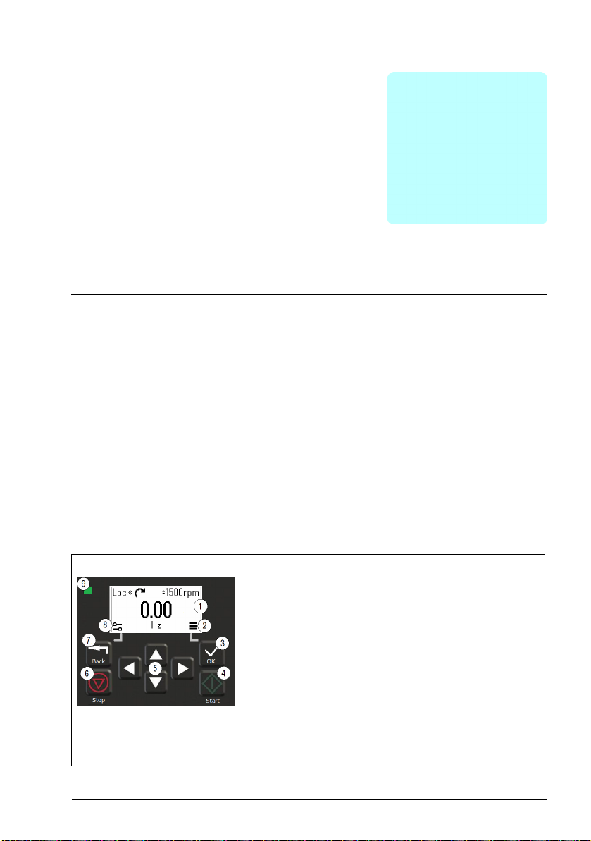
Control panel
By default, ACS 380 has an integrated panel. If required, you can use external control
panels such as assistant control panel or a basic panel. For more information, refer
ACX-AP-x assistant control panel’s user’s manual (3AUA0000085685 [English]) or
ACS-BP-S basic control panel’s user’s manual (3AXD50000032527 [English])
1. Display - shows the Home view as default.
2. Main menu.
3. OK button - open the Main menu, select and save settings.
4. Start button - start the drive.
5. Menu navigation buttons - move in the menus and set
values.
6. Stop button - stop the drive.
7. Back button - open the Options menu, and move back in
the menu.
8. Options menu.
9. Status light - green and red colors indicate the state and
potential problems.
Page 18
18 Control panel
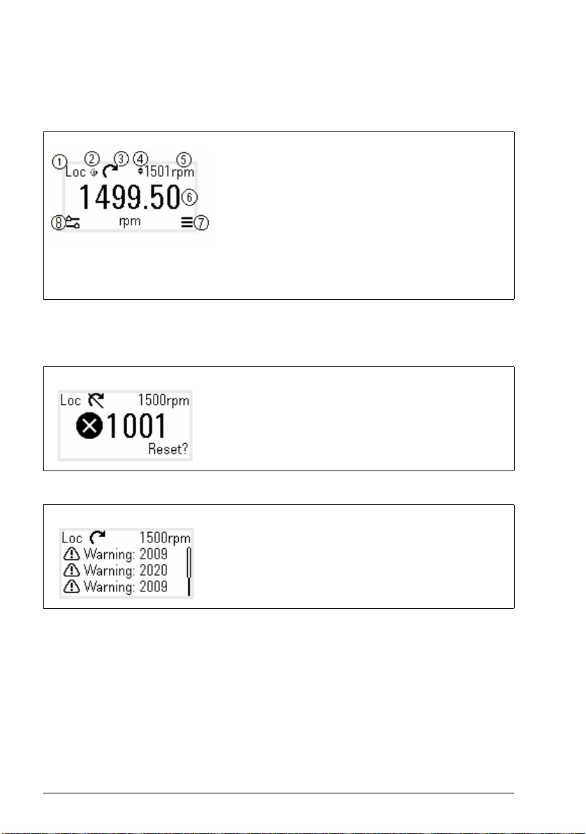
Home view and Message view
The Home view is the main view. Open the Main menu and Options menu from the
Home view.
Home view
1. Control selection - local or remote
2. Local start/stop control - enabled
3. Rotation direction - forward or reverse
4. Local reference setting - enabled
5. Speed - target
6. Speed - current
7. Main menu - menu list
8. Options menu - quick access menu
The Message view shows fault and warning messages. If there is an active fault or
warning, the panel shows the Message view directly.
You can open the Message view from the Options menu or Diagnostics submenu.
Message view: Fault
Fault messages require your immediate attention.
Check the code in the Fault messages table on page 402 to
troubleshoot the problem.
Message view: Warning
Warning messages show possible problems.
Check the code in the Warning messages table on
page 392 to troubleshoot the problem.
Page 19
Options menu and Main menu
Control panel 19
Options menu
1. To open: press the Back
button in the Home view.
Main menu
2. To open: press the OK
button in the Home view.
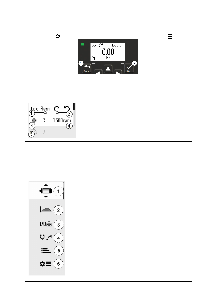
Options menu
The Options menu is a quick access menu.
1. Control location - set to local or remote control
2. Rotation direction - set to forward or reverse
3. Active faults - view possible faults
4. Reference speed - set the reference speed
5. Active warnings - view possible warnings
Main menu
The Main menu is a scroll menu. The menu icons represent specific groups. The
groups have submenus.
Note: You can define which Main menu items are visible (see parameter 49.30).
1. Motor data - motor parameters
2. Motor control - motor settings
3. Control macros
4. Diagnostics - faults, warnings, fault log and connection status
5. Energy efficiency - energy savings
6. Parameters - parameters
Page 20
20 Control panel
Submenus
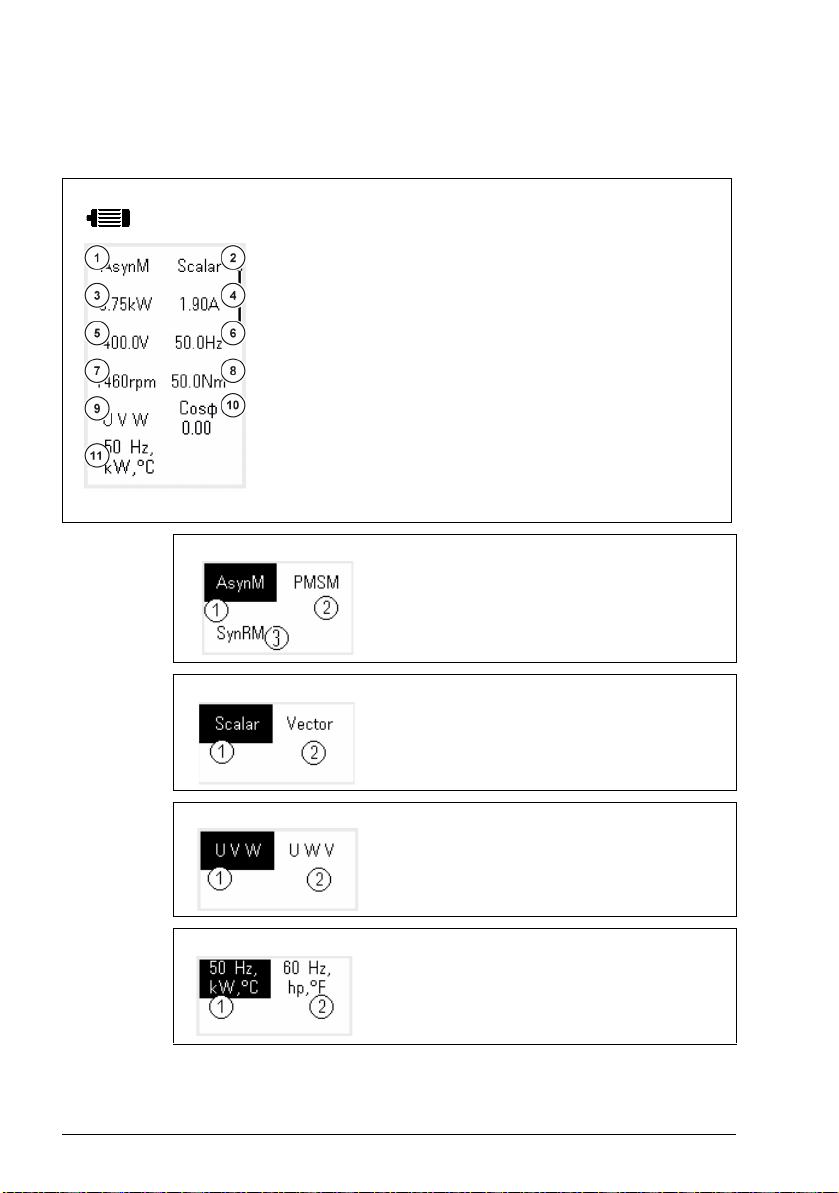
The Main menu items have submenus. Some submenus also have menus and/or option lists.
The content of the submenus depend on the drive type.
Motor Data
1. Motor type - AsynM, PMSM, SynRM
2. Control mode - Scalar, Vector
3. Nominal power
4. Nominal current
5. Nominal voltage
6. Nominal frequency
7. Nominal speed
8. Nominal torque
9. Phase order - U V W, U W V
10.Nominal Cosphi
11.Unit selection - SI or US units
Motor Data: Motor type
1. AsynM
2. PMSM
3. SynRM
Motor Data: Control mode
Motor Data: Phase order
Motor Data: Unit selection
1. Scalar
2. Vector
1. U V W
2. U W V
1. SI units
2. US units
Page 21

Motor Control
Control panel 21
1. Start mode - Const time, Automatic
2. Stop mode - Coast, Ramp, DC hold
3. Acceleration time
4. Deceleration time
5. Maximum allowed speed
6. Maximum allowed current
7. Minimum allowed speed
Motor Control: Start modes
1. Const time
2. Automatic
Motor Control: Stop modes
1. Coast
2. Ramp
3. DC hold
Control macros The control macros available depends on the option module
installed.
1. ABB standard (2-wire)
2. ABB limited (2-wire)
3. Alternate
4. Motor potentiometer
5. PID
6. Modbus RTU
7. PROFIBUS
8. PROFINET IO
9. EthernetIP
10.Modbus TCP
11. Ethe rCAT
12.CANopen
Page 22
22 Control panel
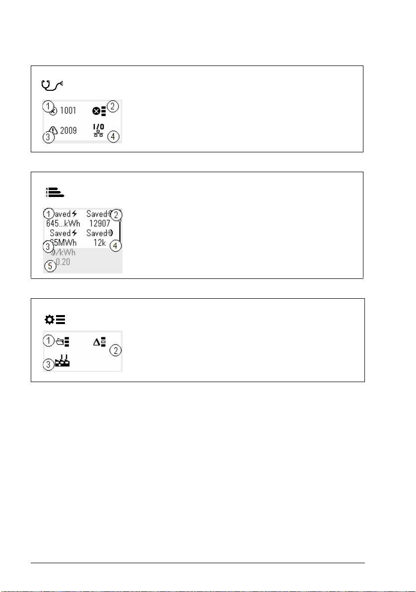
Diagnostics
Energy Efficiency
Parameters
1. Active Fault - shows the fault code
2. Fault History - list of latest fault codes (newest first)
3. Active Warnings - shows the warning code
4. Connection Status - Fieldbus and I/O signals
1. Saved energy in kWh
2. Saved money
3. Saved energy in MW
4. Saved money x 1000
5. Cost per kWh h
1. Complete parameter list - groups menu with complete
parameters and parameter levels
2. Modified parameter list
3. Parameter restore - reset to factory default parameters
Page 23

Start-up, ID run and use 23
3
Start-up, ID run and use
Contents
• Start up the drive
• Do the identification (ID) run
• Start and stop the drive
• Change the rotation direction
• Set the speed or frequency reference
• Set the drive parameters
• Open Diagnostics
• Change the units
Note: In this chapter the drive uses an integrated panel to perform the start-up, ID
run, and other actions. You can also perform these functions using an external control
panel or a drive composer PC tool.
Start up the drive
1. Select the unit (international or US) and press OK.
The drive recognizes the connected adapter and sets the correct settings. This
may take a few seconds depending on the adapter.
2. In the Motor data view, set the motor type:
AsynM: Asynchronous motor
PMSM: Permanent magnet motor, or
SynRM: Synchronous reluctance motor
3. Set the motor control mode:
Vector: Speed reference. This is suitable for most cases. The drive does an
automatic stand-still ID run.
Page 24

24 Start-up, ID run and use
Scalar: Frequency reference.
Use this mode when:
- The number of motors can change.
- The nominal motor current is less than 20% of the nominal drive current.
Scalar mode is not recommended for permanent magnet motors.
4. Set the nominal motor values:
• Nominal power
• Nominal current
• Nominal voltage
• Nominal frequency
• Nominal speed
• Nominal torque (optional)
• Nominal cosphi
5. Examine the direction of the motor.
If it is necessary, set the motor direction with the Phase order setting or with the
phase order of the motor cable.
6. In the Motor control view, set the start and stop mode.
7. Set the acceleration time and the deceleration time.
Note: The speed acceleration and deceleration ramp times are based on the
value in parameter 46.01 Speed scaling/46.02 Frequency scaling.
8. Set the maximum and minimum speed or frequency. For more information, see
parameters 30.11 Minimum speed /30.13 Minimum frequency and 30.12
Maximum speed/30.14 Maximum frequency on page 218.
9. In the Control macros view, select the applicable macro.
For units with a fieldbus adapter connected: you can see the fieldbus in the
Control macros view. There are certain parameters that you need to change, eg.
the station ID. See chapter Fieldbus control through a fieldbus adapter.
10. Tune the drive parameters to the application. You can use the Assistant control
panel (ACS-AP-x), or the Drive Composer PC tool with the drive.
Page 25

Start-up, ID run and use 25
Do the identification (ID) run
Background information
The drive automatically estimates motor characteristics using Standstill ID run when
the drive is started for the first time, and after any motor parameter (group 99 Motor
data) is changed. This is valid when:
• parameter 99.13 ID run requested selection is Standstill and
• parameter 99.04 Motor control mode selection isVector.
In most applications there is no need to perform a separate ID run. Select the ID run
for demanding motor control connections. For example:
• permanent magnet motor (PMSM) is used
• drive operates near zero speed references, or
• operation at torque range above the motor nominal torque, over a wide speed
range is needed.
Note: If you change the motor parameters after the ID run, you need to repeat the
run.
Note: If you have already parameterized your application using scalar motor control
mode and you need to change to vector:
• in the Motor data submenu, set Motor control to Vector , or set parameter 99.04
Motor control mode selection to Vector.
• for I/O controlled drive, check parameters in groups 22 Speed reference
selection, 23 Speed reference ramp, 12 Standard AI, 30 Limits and 46
Monitoring/scaling settings.
• for torque controlled drive, check also parameters in group 26 Torque reference
chain.
ID run steps
Warning! Make sure it is safe to run the procedure.
1. Open the Main menu.
2. Select the Parameters submenu.
3. Select All parameters.
4. Select 99 Motor data and press OK.
5. Select 99.13 ID run requested, select the wanted ID mode and press OK.
An AFF6 Identification run warning message is shown before you press Start.
The panel LED starts to blink green to indicate an active warning.
6. Press Start to start the ID run.
Page 26

26 Start-up, ID run and use
Do not to press any control panel keys during the ID run. If you need to stop the ID
run, press Stop.
After the ID run is completed, the status light stops blinking.
If the ID run fails, the panel shows the fault FF61 ID run.
Page 27
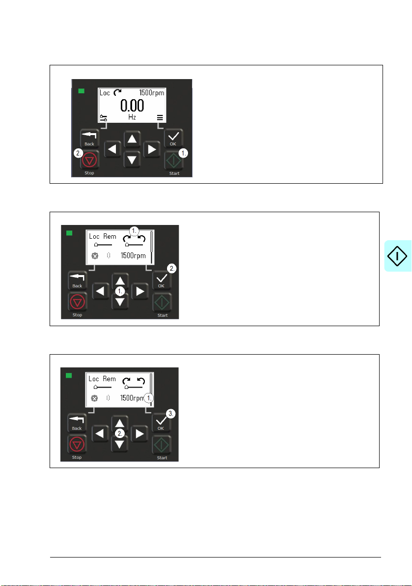
Start and stop the drive
Change the rotation direction
1. In the Options menu, move to the rotation direction
item with the arrow buttons.
2. Press the OK button to change the rotation
direction.
Start-up, ID run and use 27
1. Press the Start button to st art the drive.
2. Press the Stop button to stop the drive.
Set the speed or frequency reference
1. In the Options menu, move to the speed or
frequency reference item and press OK.
2. Press the arrow buttons to edit the value.
3. Press the OK button to confirm the new value.
Page 28
28 Start-up, ID run and use
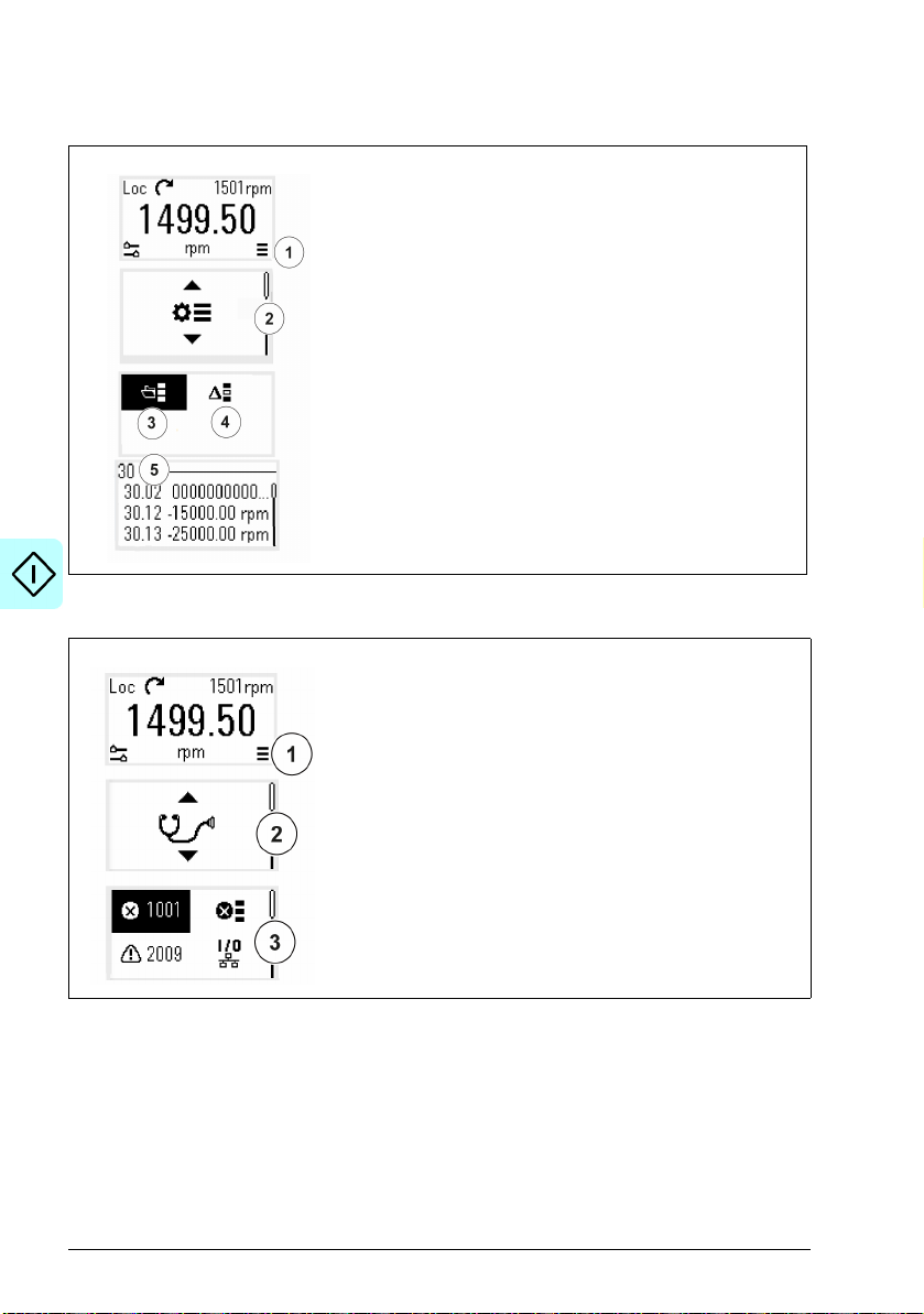
Set the drive parameters
1. Select the Main menu from the Home view.
2. Scroll to Parameters, and press the OK button to open
3. Select the complete parameters list with the arrow button
4. Select the modified parameters list with the arrow button
5. Select the parameter and press the OK button.
See chapter Parameters for more information.
Open Diagnostics
1. Select the Main menu from the Home view.
2. Scroll to Diagnostics and press the OK button to open
3. Select the warning or fault with the arrow button and
the submenu.
and press the OK button, or
and press the OK button.
The parameters are shown in respective groups. The
first two digits of the parameter number represent the
parameter group. For example, parameters starting with
30 are in the Limits group.
the submenu.
press the OK button.
See chapter Fault tracing for more information.
Page 29
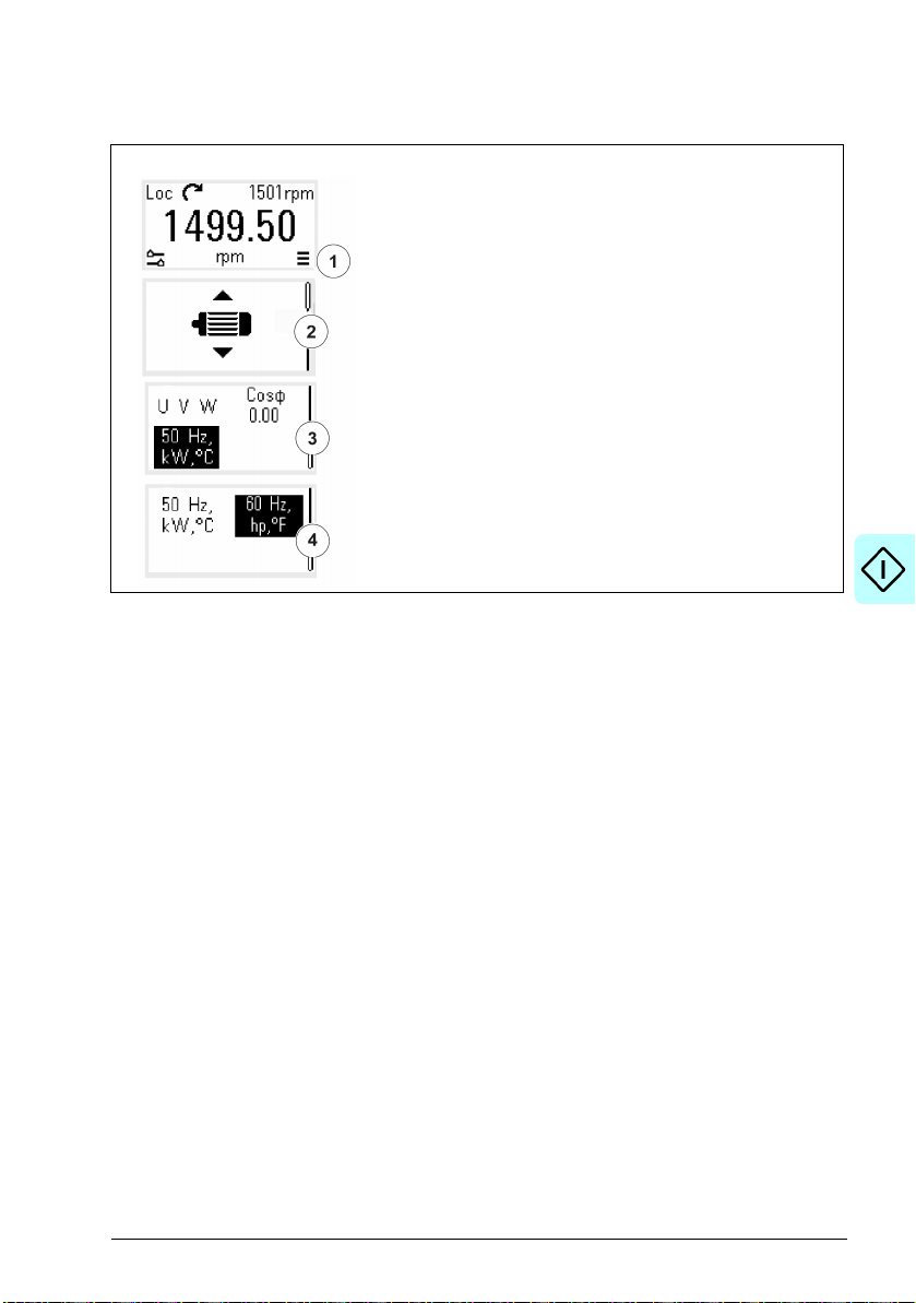
Change the units
Start-up, ID run and use 29
1. Select the Main menu from the Home view.
2. Scroll t o Motor data and press the OK button to open the
submenu.
3. Scroll to the unit selection item and press the OK button.
4. Select the unit with the arrow button, then press the OK
button.
You can see the selected unit on the Home view.
Page 30

30 Start-up, ID run and use
Page 31

4
Control macros
Contents
• ABB standard macro
• ABB limited macro
• Fieldbus control macro
• Alternate macro
• Motor potentiometer macro
• PID control macro
• Modbus macro
• Parameter default values for different macros
Control macros 31
Control macros are sets of default parameter values that apply to a specific control
configuration. They make it faster and easier to set up a drive for use.
By default, macro for I/O controlled drive is set as ABB standard macro and macro for
Fieldbus controlled drive is set as Fieldbus control macro.
Page 32

32 Control macros
ABB standard macro
ABB standard macro is suitable for an IO-controlled drive. Digital inputs control
start/stop (2-wire), direction and constant speed selection (3 speeds) and
acceleration and deceleration ramp selection.
You can activate the macro from the Control macros view, or by setting parameter
96.04 Macro select to value ABB standard.
This is the default macro for the standard drive variant (ACS380-04xS) and
configured drive variant ACS380-4xC +L538.
Page 33

Control macros 33
3)
Default control connections for the ABB standard macro
This connection diagram is valid for the standard drive variant ACS380-04xS and the
configured drive variant ACS380-04xC +L538 (with the ABB standard macro
selected).
Terminals Description
Digital I/O connections
Aux. +24 V DC, max 200 mA
Aux. volt age output common
Digital input common
Stop (0) / Start (1)
Forward (0) / Reverse (1)
Constant frequency / speed selection
Constant frequency / speed selection
Ramp set 1 input (0) / Ramp set 2 input (1)
Ready run output(0) / Not ready output (1)
Digital output auxiliary voltage
Digital input/output common
Analog I/O
Speed / freq.(0...10V)
Analog input circuit common
Not configured
Analog input circuit common
Output frequency (0...20 mA)
Analog output circuit common
Signal cable shield (screen)
Ref. voltage +10 V DC
Safe torque off (STO)
Safe torque off. Connected at factory.
Drive starts only if both circuits are closed.
4)
4)
1)
1)
2)
Relay output 1
No fault [Fault (-1)]
Notes:
Terminal sizes: 0.14 mm² … 1.5 mm²
Tightening torques: 0.5 N·m (0.4 lbf·ft).
Terminals DGND, AGND and SGND are internally connected to same reference
potential.
Page 34

34 Control macros
DI3 DI4 Operation/Parameter
Scalar control (default) Vector control
0 0 Set frequency through AI1 Set speed through AI1
1028.26 Constant frequency 1 22.26 Constant speed 1
0128.27 Constant frequency 2 22.27 Constant speed 2
1128.28 Constant frequency 3 22.28 Constant speed 3
DIO1 Ramp set Parameters
01 28.71 Freq ramp set selection,...,
28.74 Freq acceleration time 212
Reference from the integrated panel.
1)
In scalar control (default): See parameter group 28 Frequency reference chain.
In vector control
: See parameter group 22 Speed reference selection.
Select the correct control mode from the Motor data view or with parameter 99.04
Motor control mode.
2)
3)
Ground the outer shield of the cable 360 degrees under the grounding clamp on
the grounding shelf for the control cables.
4)
Select the unit for analog input AI1 in the parameter 12.15 and for AI2 in the
parameter 12.25.
Input signals
• Start/Stop selection (DI1)
• Forward (0) / Reverse (1) (DI2)
• Speed selection (DI3)
• Speed selection (DI4)
• Ramp set 1 (0) / Ramp set 2 (1) selection (DIO1)
• Output frequency or motor speed reference (AI1)
Output signals
• Output frequency (AO)
• Ready to run (0) / Not ready (1) (DIO2)
• No Fault [Fault (-1)]
Page 35

Control macros 35
ABB limited macro
The ABB limited macro is suitable for an IO-controlled drive which has the minimum
number of I/O available.
The ABB limited macro is optimized for the base drive variant (ACS380-04xN) with no
optional module connected.
You can activate the macro from the Control macros view, or by setting parameter
96.04 Macro select to value ABB limited 2-wire.
Default control connections for the ABB limited macro
This is the default control connection diagram for the base drive variant
(ACS380-04xN) with the ABB limited macro selected.
Terminals Description
Digital I/O connections
Aux. +24 V DC, max 200 mA
Aux. voltage output common
Digital input common
Stop (0) / Start (1)
Speed (1) / freq selection (2)
Safe torque off (STO)
Safe torque off. Connected at factory.
Drive starts only if both circuits are closed.
Relay output 1
No fault [Fault (-1)]
Notes:
Terminal sizes: 0.14 mm² … 1.5 mm²
Tightening torque: 0.5 N·m (0.4 lbf·ft).
Terminals DGND and SGND are internally connected to same reference potential.
Input signals
• Start / Stop (DI1)
• Output frequency or motor speed reference (DI2)
Output signals
• Relay output 1: Fault (-1)
• No Fault [Fault (-1)]
Page 36

36 Control macros
Fieldbus control macro
Fieldbus control macro is suitable for a fieldbus-controlled drive. The I/O signal
interface is not in use as default.
In the initial start-up of the drive, the fieldbus control macro activates automatically
whenever it detects a fieldbus adapter. For more information, see Automatic drive
configuration for fieldbus control on page 491.
You can activate the macro manually from the Control macros view, or by setting
parameter 96.04 Macro select to the correct value based on the selected fieldbus.
The macro is optimal for the configured variant (ACS380-04xC) which is equipped
with a fieldbus adapter module.
Default control connections for the Fieldbus macro
This is the default control connection diagram for the configured variant
(ACS380-04xC) with the Fieldbus macro selected.
Terminals Description
Digital I/O connections
Aux. +24 V DC, max 200 mA
Aux. voltage output common
Digital input common
Fault reset
Not configured
Safe torque off (STO)
Safe torque off. Connected at factory.
Drive starts only if both circuits are closed.
Relay output 1
No fault [Fault (-1)]
Fieldbus module connections
+K457 FCAN-01-M CANopen
+K454 FPBA-01-M PROFIBUS DP
+K469 FECA-01-M EtherCAT
+K475 FENA-21-M Ethernet/IP, PROFINET,
Modbus TCP
+K495 BCAN-11 CANopen interface
Notes:
Terminal sizes: 0.14 mm² … 1.5 mm²
Tightening torque: 0.5 N·m (0.4 lbf·ft).
Terminals DGND and SGND are internally connected to same reference potential.
Page 37

Control macros 37
When the fieldbus adapter module is connected, the drive control signals are
expected to come from the fieldbus typically.
When taking the drive variant ACS380-04xC +K495 (with the BCAN-11 CANopen
interface module) into use, it is recommended that the cord is not connected during
the first start. This is to avoid disturbing the CANopen bus when the drive attempts to
recognize the attached module.
The software automatically sets the relevant parameters when the fieldbus adapter
module is connected to the drive. For more information, see Automatic drive
configuration for fieldbus control on page 491. For CANopen parameters, see
CANopen parameter settings for embedded fieldbus interface on page 443.
Input signals
• Fault reset (DI1)
• Control words and reference words through the fieldbus adapter module
Output signals
• Status words and status signals through the fieldbus adapter module
• No Fault [Fault (-1)]
Page 38

38 Control macros
Alternate macro
This macro provides an I/O configuration where one signal starts the motor in the
forward direction and another signal starts the motor in the reverse direction.
You can activate the macro from the Control macros view, or by setting parameter
96.04 Macro select to value Alternate.
The macro is optimized for the standard drive variant (ACS380-04xS) and configured
drive variant ACS380-04xC +L538. You can use it also with the base drive variant
(ACS380-04xN) but then you cannot use all the I/O available in the macro.
Page 39

Control macros 39
3)
Default control connections for the Alternate macro
This connection diagram is valid for the standard drive variant ACS380-04xS and the
configured drive variant ACS380-04xC +L538 (with the Alternate macro selected).
Terminals Description
Digital I/O connections
Aux. +24 V DC, max 200 mA
Aux. voltage output common
Digital input common
Start forward; If DI1 = DI2: stop
Start reverse
Constant speed / frequency selection
Constant speed / frequency selection
Ramp set 1(0) / Ramp set 2 (1)
Ready run (0) / not ready run
Digital output auxiliary voltage
Digital input/output common
Analog I/O
Output freq./Speed ref.(0...10V)
Analog input circuit common
Not configured
Analog input circuit common
Output frequency (0...20 mA)
Analog output circuit common
Signal cable shield (screen)
Ref. voltage +10 V DC
Safe torque off (STO)
Safe torque off. Connected at factory.
Drive starts only if both circuits are closed.
4)
1)
1)
2)
4)
Relay output
No Fault [Fault (-1)
EIA-485 Modbus RTU
Embedded Modbus RTU (EIA-485). See chapter
Fieldbus control through the embedded fieldbus
interface (EFB).
Notes:
Terminal sizes: 0.14 mm² … 1.5 mm²
Tightening torque: 0.5 N·m (0.4 lbf·ft).
Terminals DGND, AGND and SGND are internally connected to same reference
potential.
Page 40

40 Control macros
DI3 DI4 Operation/Parameter
Scalar control (default) Vector control
0 0 Set frequency through AI1 Set speed through AI1
1028.26 Constant frequency 1 22.26 Constant speed 1
0128.27 Constant frequency 2 22.27 Constant speed 2
1128.28 Constant frequency 3 22.28 Constant speed 3
DIO2 Ramp
set
Parameters
Scalar control (default) Vector control
0128.72 Freq acceleration time 1 23.12 Acceleration time 1
28.73 Freq deceleration time 1 23.13 Deceleration time 1
1228.74 Freq acceleration time 2 23.14 Acceleration time 2
28.75 Freq deceleration time 2 23.15 Deceleration time 2
1)
In scalar control (default): See parameter group 28 Frequency reference chain.
In vector control
: See parameter group 22 Speed reference selection.
Select the correct control mode from the Motor data view or with parameter 99.04
Motor control mode.
2)
In scalar control (default): See parameter group 28 Frequency reference chain.
In vector control
: See parameter group 23 Speed reference ramp.
Select the correct control mode from the Motor data view or with parameter 99.04
Motor control mode.
3)
Ground the outer shield of the cable 360 degrees under the grounding clamp on
the grounding shelf for the control cables.
4)
Select the unit for analog input AI1 in the parameter 12.15 and for AI2 in the
parameter 12.25.
Input signals
• Start motor forward (DI1)
• Start motor in reverse (DI2)
• Constant output frequency / motor speed selection (DI3)
• Constant output frequency / motor speed selection (DI4)
• Ramp set selection (DIO1)
Output signals
• Output frequency or motor speed reference (AI1)
• Output frequency (AO1)
• No Fault [Fault (-1)]
Page 41

Control macros 41
Motor potentiometer macro
This macro provides a way to adjust the speed with the help of two push buttons, or a
cost-effective interface for PLCs that vary the speed of the motor using only digital
signals.
You can activate the macro from the Control macros view, or by setting parameter
96.04 Macro select to value Motor potentiometer.
For more information on the motor potentiometer counter, see section Motor
potentiometer on page 108.
The macro is optimized for the standard drive variant (ACS380-04xS) and configured
drive variant ACS380-04xC +L538.
Page 42

42 Control macros
3)
Default control connections for the Motor potentiometer macro
This connection diagram is valid for drives with the standard drive variant
ACS380-04xS and the configured drive variant ACS380-04xC +L538 (with the Motor
potentiometer macro selected).
Terminals Description
Digital I/O connections
Aux. +24 V DC, max 200 mA
Aux. voltage output common
Digital input common
Stop (0) / Start (1)
Forward (0) / Reverse (1)
Frequency / speed up
Frequency / speed down
Constant speed sel 1
Ready run (0) / Not ready run (1)
Digital output auxiliary voltage
Digital input/output common
Analog I/O
Not configured
Analog input circuit common
Not configured
Analog input circuit common
Not configured
Analog output circuit common
Signal cable shield (screen)
Ref. voltage +10 V DC
Safe torque off (STO)
Safe torque off. Connected at factory.
Drive starts only if both circuits are closed.
1)
1)
2)
4)
4)
Notes:
Terminal sizes: 0.14 mm² … 1.5 mm²
Tightening torque: 0.5 N·m (0.4 lbf·ft).
Relay output
No Fault [Fault (-1)]
Page 43

Control macros 43
DIO1 Ramp
set
Parameters
Scalar control (default) Vector control
0128.72 Freq acceleration time 1 23.12 Acceleration time 1
28.73 Freq deceleration time 1 23.13 Deceleration time 1
1228.74 Freq acceleration time 2 23.14 Acceleration time 2
28.75 Freq deceleration time 2 23.15 Deceleration time 2
Terminals DGND, AGND and SGND are internally connected to same reference
potential.
1)
When the input signal is on, the speed/frequency increase or decrease along a
parameter-defined change rate. See parameters 22.75, 22.76, and 22.77. If DI3 and
DI4 are both active or inactive, the frequency/speed reference is unchanged. The
existing frequency/speed reference is stored during stop and power down.
2)
In scalar control (default): See parameter group 28 Frequency reference chain.
In vector control
: See parameter group 23 Speed reference ramp.
Select the correct control mode from the Motor data view or with parameter 99.04
Motor control mode.
3)
Ground the outer shield of the cable 360 degrees under the grounding clamp on
the grounding shelf for the control cables.
4)
Select the unit for analog input AI1 in the parameter 12.15 and for AI2 in the
parameter 12.25.
Input signals
• Stop (0) / Start (1) (DI1)
• Forward (0) / Reverse (1) (DI2)
• Frequency / speed up (DI3)
• Frequency / speed down (DI4)
• Constant speed selection 1 (DIO1)
Output signals
• No Fault [Fault (-1)]
Page 44

44 Control macros
5)
PID control macro
This macro is suitable for applications where the drive is always controlled by PID
and the reference comes from analog input AI1.
You can activate the macro from the Control macros view, or by setting parameter
96.04 Macro select to value PID.
The macro is optimized for the standard drive variant ACS380-04xS and the
configured drive variant ACS380-04xC +L538.
Default control connections for PID control macro
This connection diagram is valid for the standard drive variant ACS380-04xS and the
configured drive variant ACS380-04xC +L538 (with the PID control macro selected).
Terminals Description
Digital I/O connections
Aux. +24 V DC, max 200 mA
Aux. voltage output common
Digital input common
Stop (0) / Start (1)
Internal setpoint sel1
Internal setpoint sel2
Constant speed / frequency selection
Run enable 1 source
Ready run
Digital output auxiliary voltage
Digital input/output common
Analog I/O
External PID ref
Analog input circuit common
Actual PID feedback
Analog input circuit common
Output frequency (0...20 mA)
Analog output circuit common
Signal cable shield (screen)
Ref. voltage +10 V DC
Safe torque off (STO)
Safe torque off. Connected at factory.
Drive starts only if both circuits are closed.
1)
1)
2)
3) 6)
4) 6)
Notes:
Terminal sizes: 0.14 mm² … 1.5 mm²
Relay output
No Fault [Fault (-1)]
Page 45

Control macros 45
Source defined
by par. 40.19
DI2
Source def ined
by par. 40.20
DI3
Internal setpoint active
00
Setpoint source: AI1 (par. 40.16)
10
1 (par. 40.21)
01
2 (par. 40.22)
11
3 (par.40.23)
DI4 Operation/Parameter
Scalar control (default) Vector control
0 Set frequency through AI1 Set speed through AI1
1 28.26 Constant frequency 1 22.26 Constant speed 1
Tightening torque: 0.5 N·m (0.4 lbf·ft).
Terminals DGND, AGND and SGND are internally connected to same reference
potential.
1)
See parameters 40.19 Set 1 internal setpoint sel1 and 40.20 Set 1 internal setpoint
sel2 source table.
2)
Select the correct control mode from the Motor data view or with parameter 99.04
Motor control mode.
3)
PID: 0...10 V -> 0...100% PID setpoint.
4)
The signal source is powered externally. See the manufacturer’s instructions. To
use sensors supplied by the drive aux. voltage output, see connection examples of
two-wire and three-wire sensors in the hardware manual of the drive.
5)
Ground the outer shield of the cable 360 degrees under the grounding clamp on
the grounding shelf for the control cables.
6)
Select the unit for analog input AI1 in the parameter 12.15 and for AI2 in the
parameter 12.25.
Input signals
•External PID ref (AI1)
• Actual feedback from PID (AI2)
• Start/Stop selection (DI1)
• Constant setpoint 1 (DI2)
• Constant setpoint 2 (DI3)
• Speed/freq selection (DI4)
• Ramp pair selection (DIO1)
Output signals
• Output frequency (AO)
• No Fault [Fault (-1)]
Page 46

46 Control macros
Modbus macro
Modbus macro is suitable for a Modbus-controlled drive.
You can activate the macro from the Control macros view, or by setting parameter
96.04 Macro select to value Modbus TCP.
The macro is optimized for the standard drive variant ACS380-04xS and the
configured drive variant ACS380-04xC +L538.
Page 47

Control macros 47
Default control connections for the Modbus macro
This connection diagram is valid for the standard drive variant ACS380-04xS and the
configured drive variant ACS380-04xC +L538 (with the Modbus macro selected).
Terminals Description
Digital I/O connections
Aux. +24 V DC, max 200 mA
Aux. voltage output common
Digital input common
Fault reset
Not configured
Not configured
Not configured
Not configured
Not configured
Digital output auxiliary voltage
Digital input/output common
Analog I/O
Not configured
Analog input circuit common
Not configured
Analog input circuit common
Not configured
Analog output circuit common
Signal cable shield (screen)
Ref. voltage +10 V DC
Safe torque off (STO)
Safe torque off. Connected at factory.
Drive starts only if both circuits are closed.
1)
1)
Relay output
No Fault [Fault (-1)]
EIA-485 Modbus RTU
Embedded Modbus RTU (EIA-485). See
chapter Fieldbus control through the
embedded fieldbus interface (EFB).
Notes:
Terminal sizes: 0.14 mm² … 1.5 mm²
Tightening torque: 0.5 N·m (0.4 lbf·ft).
Terminals DGND, AGND and SGND are internally connected to same reference
potential.
Page 48

48 Control macros
The embedded parameters also change, see the embedded macros 20.03 Ext1 in1
source (Not selected).
1)
Select the unit for analog input AI1 in the parameter 12.15 and for AI2 in the
parameter 12.25.
Input signals
• Fault reset (DI1)
• Output frequency / speed reference (AI1)
Output signals
• Output frequency (AO)
• No Fault [Fault (-1)]
Page 49

Control macros 49
Parameter default values for different macros
Chapter Parameters shows the default values of all parameters for the ABB standard
macro (factory macro). Some parameters have different default values for other
macros. The tables below lists the default values for those parameters for each
macro.
96.04 Macro select 1 =
ABB standard
10.24 RO1 source 15 = Fault (-1) 15 = Fault (-1) 15 = Fault (-1) 15 = Fault (-1)
12 =
Alternate
1
3 =
Motor potentiometer
14 =
PID
12.20 AI1 scaled at AI1
13.12 AO1 source 2 = Output
13.18 AO1 source max 50.0 50.0 50.0 50.0
19.11 Ext1/Ext2
20.01 Ext1 commands 2 = In1 Start;
20.03 Ext1 in1 source 2 = DI1 2 = DI1 2 = DI1 2 = DI1
20.04 Ext1 in2 source 3 = DI2 3 = DI2 3 = DI2 0 = Always off
20.05 Ext1 in3 source 0 = Always off 0 = Always off 0 = Always off 0 = Always off
20.06 Ext2 commands 0 = Not
20.08 Ext2 in1 source 0 = Always off 0 = Always off 0 = Always off 0 = Always off
20.09 Ext2 in2 source
20.12 Run enable 1
21.05 Emergency stop
22.11 Ext1 speed ref1 1 = AI1 scaled 1 = AI1 scaled 15 = Motor
22.18 Ext2 speed ref1 0 = Zero 0 = Zero 0 = Zero 0 = Zero
max
selection
source
source
50.0 50.0 50.0 50.0
frequency
0 = EXT1 0 = EXT1 0 = EXT1 0 = EXT1
In2 Dir
selected
0 = Always off 0 = Always off 0 = Always off 0 = Always off
1 = Selected 1 = Selected 1 = Selected 10 = DIO1
1= Inactive
(true)
2 = Output
frequency
3 = In1 Start
fwd; In2 Start
0 = Not
selected
1= Inactive
(true)
2 = Output
frequency
2 = In1 Start;
In2 Dir
0 = Not
selected
1= Inactive
(true)
potentiometer
2 = Output
frequency
1 =In1 Start
0 = Not
selected
1= Inactive
(true)
16 = PID
22.22 Constant speed
22.23 Constant speed
sel1
sel2
4 = DI3 4 = DI3 10 = DIO1 5 = DI4
5 = DI4 5 = DI4 0 = Always off 0 = Always off
Page 50

50 Control macros
96.04 Macro select 1 =
22.71 Motor
potentiometer
function
22.73 Motor
potentiometer up
source
22.74 Motor
potentiometer
down source
23.11 Ramp set
selection
28.11 Ext1 frequency
ref1
28.15 Ext1 frequency
ref2
28.22 Constant
frequency sel1
28.23 Constant
frequency sel2
28.71 Freq ramp set
selection
40.07 Process PID
operation mode
40.16 Set 1 setpoint 1
source
40.17 Set 1 setpoint 2
source
40.19 Set 1 internal
setpoint sel1
40.20 Set 1 internal
setpoint sel2
40.32 Set 1 gain 1.00 1.00 1.00 1.00
ABB standard
0 = Disabled 0 = Disabled 1 = Enabled
0 = Not
selected
0 = Not
selected
10 = DIO1 10 = DIO1 0 = Acc/Dec
1 = AI1 scaled 1 = AI1 scaled 15 = Motor
0 = Zero 0 = Zero 0 = Zero 0 = Zero
4 = DI3 4 = DI3 10 = DIO1 5 = DI4
5 = DI4 5 = DI4 0 = Always o ff 0 = Always off
10 = DIO1 10 =DIO1 0 =
0 = Off 0 = Off 0 = Off 2 = On when
11 = AI1
percent
0 = Not
selected
0 = Not
selected
0 = Not
selected
12 =
Alternate
0 = Not
selected
0 = Not
selected
11 = AI1
percent
0 = Not
selected
0 = Not
selected
0 = Not
selected
1
3 =
Motor potentiometer
(init at powerup)
4 = DI3 0 = Not
5 = DI4 0 = Not
time 1
potentiometer
Acc/Dec
time 1
11 = AI1
percent
0 = Not
selected
0 = Not
selected
0 = Not
selected
14 =
PID
0 = Disabled
selected
selected
0 = Acc/Dec
time 1
16 = PID
0 = Acc/Dec
time 1
drive running
11 = AI1
percent
2 = Internal
setpoint
3 = DI2
4 = DI3
40.33 Set 1 integration
time
60.0 60.0 60.0 60.0
Page 51

5
Program features
Contents
• Local and external control locations
• Operating modes and motor control modes
• Drive configuration and programming
• Control interfaces
• Motor control
• Application control
• DC voltage control
• Limit to limit control
• Safety and protections
• Diagnostics
• Miscellaneous
Program features 51
Page 52

52 Program features
Integrated panel, Assistant
control panel (optional) or Drive
composer PC tool (optional)
Fieldbus adapter (Fxxx)
MOTOR
PLC
(= Programmable
logic controller)
I/O
Embedded fieldbus
interface
External control
Local control
Drive
M
3~
Local and external control locations
There are two main control locations: local and external. Select the control by
pressing the Loc/Rem key on the panels, or from the Drive composer PC tool.
Local control
The control commands are given from the integrated control panel or from a PC
equipped with Drive composer when the drive is in local control. Local control is
mainly used during commissioning and maintenance. The control panel always
overrides the external control signal sources when used in local control.
Changing the control location to local can be prevented by parameter 19.17 Local
control disable.
Note: You can use both assistant control panel/drive composer tool at the same time,
but only one can be in local control at a time.
Settings
Parameters 19.17 Local control disable (page 155) and 49.05 Communication loss
action page (293).
Page 53

Program features 53
Timed function 1…3
Supervision 1…6
Other [ bit]
DI1
DI0 2
EXT1
Run enable
EFB MCW b it 3
Select
20.12
DI1
DIO2
FB A A MCW bi t 3
0
1
Off
Selected
Embedded fieldbus
Timed function
A bit in a parameter
Supervision
Fieldbus adapter
External control
When the drive is in external control, control commands are given through:
• the I/O terminals (digital and analog inputs)
• the fieldbus interface (via the embedded fieldbus interface or an optional fieldbus
adapter module)
• external panel (assistant panel).
Two external control locations, EXT1 and EXT2, are available. You can select the
sources of the start and stop commands separately for each location by setting
parameters 20.01...20.10. The operating mode can be selected separately for each
location, which enables quick switching between different operating modes, for
example speed and torque control. Selection between EXT1 and EXT2 is done via
any binary source such as a digital input or fieldbus control word by parameter 19.11
Ext1/Ext2 selection. You can also select the source of reference for each operating
mode separately, and the operation mode.
Settings
Parameters 20.01... 20.10 and 19.11 Ext1/Ext2 selection (page154).
Block diagram: Run enable source for EXT1
The figure below shows the parameters that select the interface for run enable for
external control location EXT1.
Settings
Parameters 19.11 Ext1/Ext2 selection (page154) and 20.01…20.10.
Page 54

54 Program features
Frequency reference
Parameter group 26
Torque reference chain
Speed reference
Parameter group 26
Torque reference
Tor que refere nce
Parameter group 26
Torque reference
Process PID
Vector motor control mode Scalar motor control mode
Frequency controllerTorque contro ller
Operating modes and motor control modes
The drive can operate in several operating modes with different types of reference.
The operating mode is selectable for each control location (Local, EXT1 and EXT2)
when the motor control mode is Vector (99.04). If the motor control mode is Scalar,
the drive operation mode is fixed to frequency control mode.
An overview of the control hierarchy and different reference types and control chains
is shown below.
Settings
Parameter group 19 Operation mode (page 153).
Overview diagram of control hierarchy
The following is a more detailed representation of the drive control hierarchy
reference types and control chains.
Page 55

Program features 55
Process PID setpoint and
feedback source selection
Tor que reference
source selection and
modification
Speed reference
source selection I
Frequency reference
source selection and
modification
Speed reference source
selection II
Speed reference ramping and
shaping
Speed error calculation
Vector motor control mode Scalar motor control mode
Speed controller
Process PID controller
Torque limitation
Reference selection for torque
controller
Frequency controllerTorque controller
Page 56

56 Program features
Speed control mode
In speed control mode, the motor follows a speed reference given to the drive. This
mode can be used with either estimated or measured speed used as feedback.
Speed control mode is available in both local and external control locations. It is
supported in vector motor control only.
Speed control uses speed reference chain. Select speed reference with parameters
in group 22 Speed reference selection on page 177.
Torque control mode
In torque control mode, the motor torque follows a torque reference given to the drive.
Torque control mode is available in both local and external control locations. It is
supported in vector motor control only.
Torque control uses torque reference chain. Select torque reference with parameters
in group 26 Torque reference chain on page 199.
Frequency control mode
In frequency control mode, the motor follows the drive output frequency reference.
Frequency control is available in both local and external control location. It is
supported in scalar motor control only.
Frequency control uses frequency reference chain. Select frequency reference with
parameters in group 28 Frequency reference chain on page 203.
Special control modes
In addition to the above-mentioned operating modes, the following special operating
modes are available:
• Process PID control. For more information, see section Process PID control on
page 81.
• Emergency stop modes OFF1 and OFF3: Drive stops along the defined
deceleration ramp and drive modulation stops.
• Jogging mode: Drive starts and accelerates to the defined speed when the
jogging signal is activated. For more information, see section Jogging on page 70.
• Pre-magnetization: DC magnetization of the motor before start. For more
information, see section Pre-magnetization on page 77.
• DC hold: Locking the rotor at (near) zero speed in the middle of normal operation.
For more information, see section DC hold on page 77.
• Pre-heating (motor heating): Keeping the motor warm when the drive is stopped.
For more information, see section Pre-heating (Motor heating) on page 78.
Page 57

Program features 57
ș
Absolute encoder/re solver
Rotor
N
S
Settings
Parameter groups 19 Operation mode (page153) and 99.04 Motor control mode
(page 347).
Autophasing
Autophasing is an automatic measurement routine to determine the angular position
of the magnetic flux of a permanent magnet synchronous motor or the magnetic axis
of a synchronous reluctance motor. The motor control requires the absolute position
of the rotor flux in order to control motor torque accurately.
Sensors like absolute encoders and resolvers indicate the rotor position at all times
after the offset between the zero angle of rotor and that of the sensor has been
established. On the other hand, a standard pulse encoder determines the rotor
position when it rotates but the initial position is not known. However, a pulse encoder
can be used as an absolute encoder if it is equipped with Hall sensors, albeit with
coarse initial position accuracy. Hall sensors generate so-called commutation pulses
that change their state six times during one revolution, so it is only known within
which 60° sector of a complete revolution the initial position is.
Many encoders give a zero pulse (also called Z-pulse) once during each rotation. The
position of the zero pulse is fixed. If this position is known with respect to zero
position used by motor control, the rotor position at the instant of the zero pulse is
also known.
Using the zero pulse improves the robustness of the rotor position measurement. The
rotor position must be determined during starting because the initial value given by
the encoder is zero. The autophasing routine determines the position, but there is a
risk of some position error. If the zero pulse position is known in advance, the position
found by autophasing can be corrected as soon as the zero pulse is detected for the
first time after starting.
Page 58

58 Program features
The autophasing routine is performed with permanent magnet synchronous motors
and synchronous reluctance motors in the following cases:
1. One-time measurement of the rotor and encoder position difference when an
absolute encoder, a resolver, or an encoder with commutation signals is used
2. At every power-up when an incremental encoder is used
3. With open-loop motor control, repetitive measurement of the rotor position at
every start
4. When the position of the zero pulse must be measured before the first start after
power-up.
Note: In closed-loop control, autophasing is performed automatically after the motor
identification run (ID run). Autophasing is also performed automatically before starting
when necessary.
In open-loop control, the zero angle of the rotor is determined before starting. In
closed-loop control, the actual angle of the rotor is determined with autophasing when
the sensor indicates zero angle. The offset of the angle must be determined because
the actual zero angles of the sensor and the rotor do not usually match. The
autophasing mode determines how this operation is done both in open-loop and
closed-loop control.
The rotor position offset used in motor control can also be given by the user – see
parameter 98.15 Position offset user. Note that the autophasing routine also writes its
result into this parameter. The results are updated even if user settings are not
enabled by 98.01 User motor model mode.
Note: In open-loop control, the motor always turns when it is started as the shaft is
turned towards the remanence flux.
Bit 4 of 06.21 Drive status word 3 indicates if the rotor position has already been
determined.
Autophasing modes
The ACS380 uses turning mode (see parameter 21.13 Autophasing mode).
The turning mode (Turning ) is the most robust and accurate method. In turning mode,
the motor shaft is turned back and forward (±360/polepairs)° in order to determine the
rotor position. In case 3 (open-loop control), the shaft is turned only in one direction
and the angle is smaller.
The drive is capable of determining the rotor position when started into a running
motor in open-loop or closed-loop control. In this situation, the setting of 21.13
Autophasing mode has no effect.
The autophasing routine can fail and therefore it is recommended to perform the
routine several times and check the value of parameter 98.15 Position offset user.
Page 59

Program features 59
An autophasing fault (3385 Autophasing) can occur with a running motor if the
estimated angle of the motor differs too much from the measured angle. This could
be caused by, for example, the following:
• The encoder is slipping on the motor shaft
• An incorrect value has been entered into 98.15 Position offset user
• The motor is already turning before the autophasing routine is started
• Turning mode is selected in 21.13 Autophasing mode but the motor shaft is
locked
• The wrong motor type is selected in 99.03 Motor type
• Motor ID run has failed.
Settings
Parameters 06.21 Drive status word 3 (page 128), 21.13 Autophasing mode (page
173), 98.15 Position offset user (page 347) and 99.13 ID run requested (page 350).
Page 60

60 Program features
Application program
Firmware
Speed control
Torque control
Frequency control
Drive logic
I/O interface
Fieldbus interface
Protections
Parameter
interface
Function block
program
Standard block
library
M
Drive configuration and programming
The drive control program is divided into two parts:
• firmware program
• application program
Drive control program
The firmware program performs the main control functions, including speed, torque
and frequency control, drive logic (start/stop), I/O, feedback, communication and
protection functions. Firmware functions are configured and programmed with
parameters, and can be extended by application programming
Programming via parameters
Parameters configure all of the standard drive operations and can be set via
• the integrated panel, as described in chapter Control panel
• an external panel
• the Drive composer PC tool, as described in Drive composer PC tool user’s
manual (3AUA0000094606 [English]), or
• the fieldbus interface, as described in chapters Fieldbus control through the
embedded fieldbus interface (EFB) and Fieldbus control through a fieldbus
adapter.
All parameter settings are stored automatically to the permanent memory of the drive.
However, if an external +24 V DC power supply is used for the drive control unit, it is
highly recommended to force a save by using parameter 96.07 Parameter save
manually before powering down the control unit after any parameter changes have
been made.
If necessary, the default parameter values can be restored by parameter 96.06
Parameter restore.
Page 61

Program features 61
Adaptive programming
Conventionally, you can control the operation of the drive by parameters. However,
the standard parameters have a fixed set of choices or a setting range. To further
customize the operation of the drive, an adaptive program can be constructed out of a
set of function blocks.
The Drive composer pro PC tool (version 1.11 or later, available separately) has an
Adaptive programming feature with a graphical user interface for building the custom
program. The function blocks include the usual arithmetic and logical functions, as
well as e.g., selection, comparison and timer blocks.
The physical inputs, drive status information, actual values, constants and
parameters can be used as the input for the program. The output of the program can
be used e.g., as a start signal, external event or reference, or connected to the drive
outputs. See the table below for a listing of the available inputs and outputs.
If you connect the output of the adaptive program to a selection parameter that is a
pointer parameter, the selection parameter will be write-protected.
Example:
If parameter 31.01 External event 1 source is connected to an adaptive
programming block output, the parameter value is shown as Adaptive program on
a control panel or PC-tool. The parameter is write-protected (= the selection
cannot be changed).
The status of the adaptive program is shown by parameter 07.30 Adaptive program
status.
For more information, see the Adaptive programming application guide
(3AXD50000028574 [English]).
Inputs available to the adaptive program
Input So urce
I/O
DI1 10.02 DI delayed status, bit 0
DI2 10.02 DI delayed status, bit 1
DI3 10.02 DI delayed status, bit 2 1)
DI4 10.02 DI delayed status, bit 3 1)
AI1 12.11 AI1 actual value 1)
AI2 12.21 AI2 actual value 1)
DIO1 11 .02 DIO delayed status, bit 0 1)
DIO2 11 .02 DIO delayed status, bit 1 1)
Actual signals
Motor speed 01.01 Motor speed used
Output frequency 01.06 Output frequency
Motor current 01.07 Motor current
Motor torque 01.10 Motor torque
Motor shaft power 01.17 Motor shaft power
Status
Enabled 06.16 Drive status word 1, bit 0
Page 62

62 Program features
Inputs available to the adaptive program
Input S ource
Inhibited 06.16 Drive status word 1, bit 1
Ready to start 06.16 Drive status word 1, bit 3
Tripped 06.11 Main status word, bit 3
At setpoint 06.11 Main status word, bit 8
Limiting 06.16 Drive status word 1, bit 7
Ext1 active 06.16 Drive status word 1 , bit 10
Ext2 active 06.16 Drive status word 1 , bit 11
Data storage
Data storage 1 real 32 47.01 Data storage 1 real32
Data storage 2 real 32 47.02 Data storage 2 real32
Data storage 3 real 32 47.03 Data storage 3 real32
Data storage 4 real 32 47.04 Data storage 4 real32
1)
Available only if I/O and Modbus module is connected and in use.
Outputs available to the adaptive program
Output Target
I/O
RO1 10.24 RO1 source
AO1 13.12 AO1 source 2)
DIO1 11 .0 6 DIO1 output source 2)
DIO2 11 .1 0 DIO2 output source 2)
Start con trol
Ext1/Ext2 selection 19.11 Ext1/Ext2 selection
Run enable 1 20.12 Run enable 1 source
Ext1 in1 cmd 20.03 Ext1 in1 source
Ext1 in2 cmd 20.04 Ext2 in2 source
Ext1 in3 cmd 20.05 Ext1 in3 source
Ext2 in1 cmd 20.08
Ext2 in2 cmd 20.09 Ext2 in2 source
Ext2 in3 cmd 20.10 Ext2 in3 source
Fault reset 31.11 Fault reset selec tion
Speed control
Ext1 speed reference 22.11 Ext1 speed ref1
Speed proportional gain 25.02 Speed proportional gain
Speed integration time 25.03 Speed integration time
Acceleration time 1 23.12 Acceleration time 1
Deceleration time 1 23 .13 Deceleration time 1
Frequency control
Ext1 frequency reference 28.11 Ext1 frequency ref1
Torque control
Ext1 torque reference 26.11 Torque ref1 source
Ext2 torque reference 26.12 Torque ref2 source
Limit function
Minimum torque 2 30.21 Min torque 2 source
Maximum torque 2 30.22 Max torque 2 source
Events
External event 1 31.01 External event 1 source
External event 2 31.03 External event 2 source
External event 3 31.05 External event 3 source
Ext2 in1 source
Page 63

Program features 63
Outputs available to the adaptive program
Output Target
External event 4 31.07 External event 4 source
External event 5 31.09 External event 5 source
Data Storage
Data storage 1 real32 47.01 Data storage 1 real32
Data storage 2 real32 47.02 Data storage 2 real32
Data storage 3 real32 47.03 Data storage 3 real32
Data storage 4 real32 47.04 Data storage 4 real32
Process PID
Set 1 setpoint 1 40.16 Set 1 setpoint 1 source
Set 1 setpoint 2 40.17 Set 1 setpoint 2 source
Set 1 feedback 1 40.0 8 Set 1 feedback 1 source
Set 1 feedback 2 40.0 9 Set 1 feedback 2 source
Set 1 gain 40.32 Set 1 gain
Set 1 integration time 40.33 Set 1 integration time
Set 1 tracking mode 40.49 Set 1 tracking mode
Set 1 track reference 40.5 0 Set 1 tracking ref selection
2)
Available only if I/O and Modbus module is connected and in use.
Adaptive program fault and aux code formats
The format of the aux code:
Bits 24-31: State number Bits 16-23: block number Bits 0-15: error code
If the state number is zero but the block number has a value, the fault is related to a
function block in the base program. If both state number and block number are zero,
the fault is a generic fault that is not related to a specific block.
Sequence program
An adaptive program can contain base program and sequence program parts. Base
program is run continuously when adaptive program is in running mode. The
functionality of the base program is programmed using function blocks and system
inputs and outputs.
Sequence program is a state machine. This means that only one state of the
sequence program is run at a time. You can create a sequence program by adding
states and programming the state programs using the same program elements as in
the base program. You can program state transitions by adding state transition
outputs to the state programs. The state transition rules are programmed using
function blocks.
The number of the active state of the sequence program is shown by parameter
07.31 AP sequence state.
Page 64

64 Program features
Control interfaces
The number of inputs and outputs depend on the product variant and if the drive is
equipped with any optional I/O extension modules.
S variant:
• 4 x Digital Inputs
• 2 x Digital Inputs/Outputs
• 2 x Analog Inputs
• 1 x Analog Output
• 1 x Relay Output
C variant:
• 2 x Digital Inputs
• 1 x Relay Output
Programmable analog inputs
There are max two programmable analog inputs. Each of the inputs can be
independently set as a voltage (0/2…10 V) or current (0/4…20 mA) input by a switch
on the control unit. Each input can be filtered, inverted and scaled.
Settings
Parameter group 12 Standard AI (page 141).
Programmable analog outputs
There is max one current (0...20mA) analog output. The output can be filtered,
inverted and scaled.
Settings
Parameter group 13 Standard AO (page146).
Programmable digital inputs and outputs
There are max four digital inputs, and two digital inputs/outputs (I/O that can be set as
either an input or an output).
Digital inputs DI3 and DI4 can be used as frequency input and digital outputs DIO1
and DIO2 can be used as frequency output.
Settings
Parameter groups 10 Standard DI, RO (page 131) and 11 Standard DIO, FI, FO
(page 135).
Page 65

Program features 65
Programmable relay outputs
There is one relay output as standard. The signal indicated by the output can be
selected by parameters.
Settings
Parameter groups 10 Standard DI, RO (page 131).
Programmable I/O extensions
Inputs and outputs can be added by using I/O extension modules.
The table below shows the number of I/O on the control unit as well as optional I/O
extension modules.
Location Digital
inputs
(DI)
Base unit 2----1
BREL -----4
BIO-01 3 1 - 1 - -
Digital
outputs
(DO)
Digital
I/Os
(DIO)
Analog
inputs
(AI)
Analog
outputs
(AO)
Note: The configuration parameter group contains parameters that display the values
of the inputs on the extension module. These parameters are the only way of utilizing
the inputs on an I/O extension module as signal sources.
Relay
outputs
(RO)
Settings
Parameter groups 15 I/O extension module (page 149).
Fieldbus control
The drive can be connected to several different automation systems through its
fieldbus interfaces. See chapters Fieldbus control through the embedded fieldbus
interface (EFB) and Fieldbus control through a fieldbus adapter.
Settings
Parameter groups 50 Fieldbus adapter (FBA) (page 295), 51 FBA A settings (page
299), 52 FBA A data in (page 300), 53 FBA A data out (page 301) and 58 Embedded
fieldbus (page 301).
Page 66

66 Program features
Motor control
Motor types
The drive supports the following motor types:
• Asynchronous AC induction motors
• Permanent magnet (PM) motors
• Synchronous reluctance motors (SynRM).
Settings
Parameter 99.03 Motor type (page 347).
Motor identification
The performance of vector control is based on an accurate motor model determined
during the motor start-up.
A motor Identification magnetization is automatically performed the first time the start
command is given. During this first start-up, the motor is magnetized at zero speed
for several seconds to allow the motor model to be created. This identification method
is suitable for most applications.
In demanding applications a separate Identification run (ID run) can be performed.
Settings
Parameter 99.13 ID run requested (page 350).
Power loss ride-through
See section Undervoltage control (power loss ride-through) on page 90.
Vector control
Vector control is the motor control mode which is intended for applications where high
control accuracy is needed. It requires an identification run at startup. Vector control
cannot be used in all applications.
The switching of the output semiconductors is controlled to achieve the required
stator flux and motor torque. The switching frequency is changed only if the actual
torque and stator flux values differ from their reference values by more than the
allowed hysteresis. The reference value for the torque controller comes from the
speed controller or directly from an external torque reference source.
Motor control requires measurement of the DC voltage and two motor phase
currents. Stator flux is calculated by integrating the motor voltage in vector space.
Motor torque is calculated as a cross product of the stator flux and the rotor current.
By utilizing the identified motor model, the stator flux estimate is improved. Actual
motor shaft speed is not needed for the motor control.
Page 67

Program features 67
The main difference between traditional control and vector control is that torque
control operates at the same time level as the power switch control. There is no
separate voltage and frequency controlled PWM modulator; the output stage
switching is wholly based on the electromagnetic state of the motor.
The best motor control accuracy is achieved by activating a separate motor
identification run (ID run).
See also section Speed control performance figures on page 73.
Settings
Parameters 99.04 Motor control mode (page 347) and 99.13 ID run requested (page
350).
Reference ramping
Acceleration and deceleration ramping times can be set individually for speed, torque
and frequency reference.
With a speed or frequency reference, the ramps are defined as the time it takes for
the drive to accelerate or decelerate between zero speed or frequency and the value
defined by parameter 46.01 Speed scaling or 46.02 Frequency scaling. The user can
switch between two preset ramp sets using a binary source such as a digital input.
For speed reference, also the shape of the ramp can be controlled.
With a torque reference, the ramps are defined as the time it takes for the reference
to change between zero and nominal motor torque (01.30 Nominal torque scale).
Variable slope
Variable slope controls the slope of the speed ramp during a reference change. With
this feature a constantly variable ramp can be used.
Variable slope is only supported in remote control.
Settings
Parameters 23.28 Variable slope enable (page 192) and 23.29 Variable slope rate
(page 192).
Special acceleration/deceleration ramps
The acceleration/deceleration times for the jogging function can be defined
separately; see section Jogging on page 70.
The change rate of the motor potentiometer function (page 108) is adjustable. The
same rate applies in both directions.
A deceleration ramp can be defined for emergency stop (“Off3” mode).
Page 68

68 Program features
Settings
• Speed reference ramping - Parameters 23.11…23.15, 23.32 Shape time 1 (page
193), 23.33 Shape time 2 (page 193) and 46.01 Speed scaling (page 289).
• Torque reference ramping - Parameters 01.30 Nominal torque scale (page 117 ),
26.18 Torque ramp up time (page 202) and 26.19 Torque ramp down time (page
202).
• Frequency reference ramping - Parameters 28.71…28.75 and 46.02 Frequency
scaling (page 289).
• Jogging - Parameters 23.20 Acc time jogging (page 191) and 23.21 Dec time
jogging (page 191).
• Motor potentiometer - Parameter 22.75 Motor potentiometer ramp time (page
187).
• Emergency stop (“Off3” mode) - Parameter 23.23 Emergency stop time (page
192).
Constant speeds/frequencies
Constant speeds and frequencies are predefined references that can be quickly
activated, for example, through digital inputs. It is possible to define up to 7 speeds
for speed control and 7 constant frequencies for frequency control.
WAR NIN G: Speeds and frequencies override the normal reference
irrespective of where the reference is coming from.
Settings
Parameter groups 22 Speed reference selection (page 177) and 28 Frequency
reference chain (page 203).
Critical speeds/frequencies
Critical speeds (sometimes called “skip speeds”) can be predefined for applications
where it is necessary to avoid certain motor speeds or speed ranges because of, for
example, mechanical resonance problems.
The critical speeds function prevents the reference from dwelling within a critical band
for extended times. When a changing reference enters a critical range, the output of
the function freezes until the reference exits the range. Any instant change in the
output is smoothed out by the ramping function further in the reference chain.
When the drive is limiting the allowed output speeds/frequencies, it limits to the
absolutely lowest critical speed (critical speed low or critical frequency low) when
accelerating from standstill, unless the speed reference is over the upper critical
speed/ frequency limit.
Page 69

Program features 69
540
690
1380
1560
1Par. 22.52 = 540 rpm
2Par. 22.53 = 690 rpm
3Par. 22.54 = 1380 rpm
4Par. 22.55 = 1560 rpm
1234
22.01 Speed ref unlimited (rpm)
(output of function)
22.87 Speed reference act 7 (rpm)
(input of function)
Example
A fan has vibrations in the range of 540 to 690 rpm and 1380 to 1560 rpm. To make
the drive avoid these speed ranges,
• enable the critical speeds function by turning on bit 0 of parameter 22.51, and
• set the critical speed ranges as in the figure below.
Settings
• Critical speeds - Parameters 22.51…22.57.
• Critical frequencies - Parameters 28.51…28.57.
• Function input (speed) - Parameter 22.01 Speed ref unlimited (page 177).
• Function output (speed) - Parameter 22.87 Speed reference act 7 (page 188).
• Function input (frequency) - Parameter 28.96 Frequency ref act 7 (page 215).
• Function output (frequency) - Parameter 28.97 Frequency ref unlimited (page
215).
Page 70

70 Program features
Motor speed
Time
Overspeed trip level
Overspeed trip level
31.30 Overspeed trip margin
0
31.30 Overspeed trip margin
30.12
30.11
Rush cont rol active
Rush control
Rush control is automatically on when the operation mode is torque. In torque control,
the motor could potentially rush if the load were suddenly lost. The control program
has a rush control function that decreases the torque reference whenever the motor
speed exceeds the set minimum speed or maximum speed.
The function is based on a PI controller. The program sets the proportional gain to
10.0 and integration time to 2.0 s.
Settings
Parameters 30.11 Minimum speed (page 217), 30.12 Maximum speed (page 217)
and 31.30 Overspeed trip margin (page 229).
Encoder echo support
The connection of one encoder to several drives with the BTAC-02 encoder interface
module can be done by using a daisy chain wiring scheme. This means wiring
channels A, B, Z and GND of multiple encoder modules together with the encoder.
Settings
Parameter groups 90 Feedback selection (page 327), 91 Encoder adapter settings
(page 328) and 92 Encoder 1 configuration (page 329).
Jogging
The jogging function enables the use of a momentary switch to briefly rotate the
motor. The jogging function is typically used during servicing or commissioning to
control the machinery locally.
Two jogging functions (1 and 2) are available, each with their own activation sources
and references. The signal sources are selected by parameters 20.26 and 20.27.
Page 71

Program features 71
2314568 11 13141516
t
71891210 17
Jog cmd
Jog enable
Start cmd
Speed
When jogging is activated, the drive starts and accelerates to the defined jogging
speed along the defined jogging acceleration ramp. After the activation signal
switches off, the drive decelerates to a stop along the defined jogging deceleration
ramp.
The figure and table below provide an example of how the drive operates during
jogging. In the example, the ramp stop mode is used (21.03 Stop mode).
Jog cmd = State of source set by 20.26 or 20.27
Jog enable = State of source set by 20.25
Start cmd = State of drive start command.
Jog
Jog
Phase
cmd
enable
1-2 1 1 0 Drive accelerates to the jogging speed along the acceleration
2-3 1 1 0 Drive follows the jog reference.
3-4 0 1 0 Drive decelerates to zero speed along the deceleration ramp
4-5 0 1 0 Drive is stopped.
5-6 1 1 0 Drive accelerates to the jogging speed along the acceleration
6-7 1 1 0 Drive follows the jog reference.
7-8 0 1 0 Drive decelerates to zero speed along the deceleration ramp
8-9 0 1->0 0 Drive is stopped. As long as the jog enable signal is on, start
9-10 x 0 1 Drive accelerates to the speed reference along the selected
Start
cmd
ramp of the jogging function.
of the jogging function.
ramp of the jogging function.
of the jogging function.
commands are ignored. After jog enable switches off, a fresh
start command is required.
acceleration ramp (parameters 23.11…23.15).
Description
Page 72

72 Program features
Jog
Jog
Phase
cmd
enable
10-11 x 0 1 Drive follows the speed reference.
11-12 x 0 0 Drive decelerates to zero speed along the selected
12-13 x 0 0 Drive is stopped.
13-14 x 0 1 Drive accelerates to the speed reference along the selected
14-15 x 0->1 1 Drive follows the speed reference. As long as the start
15-16 0->1 1 0 Start command switches off. The drive starts to decelerate
16-17 1 1 0 Drive follows the jog reference.
17-18 0 1->0 0 Drive decelerates to zero speed along the deceleration ramp
Start
cmd
deceleration ramp (parameters 23.11…23.15).
acceleration ramp (parameters 23.11…23.15).
command is on, the jog enable signal is ignored. If the jog
enable signal is on when the start command switches off,
jogging is enabled immediately.
along the selected deceleration ramp (parameters
23.11…23.15).
When the jog command switches on, the decelerating drive
adopts the deceleration ramp of the jogging function.
of the jogging function.
Description
Notes:
• Jogging is not available when the drive is in local control.
• Jogging cannot be enabled when the drive start command is on, or the drive
started when jogging is enabled. Starting the drive after the jog enable switches
off requires a fresh start command.
WAR NIN G! If jogging is enabled and activated while the start command is on,
jogging will activate as soon as the start command switches off.
• If both jogging functions are activated, the one that was activated first has priority.
• Jogging uses vector control.
• The inching functions activated through fieldbus (06.01 bits 8…9) use the
references and ramp times defined for jogging, but do not require the jog enable
signal.
Settings
Parameters 20.25 Jog enable (page 164), 20.26 Jog 1 start (page 165), 20.27 Jog 2
start (page 166), 22.42 Jogging 1 ref (page 185), 22.43 Jogging 2 ref (page 185),
23.20 Acc time jogging (page 191) and 23.21 Dec time jogging (page 191).
Page 73

Program features 73
100
t (s)
T
T
N
(%)
T
load
n
act-nref
n
N
Area < 10% s
TN= rated motor torque
n
N
= rated motor speed
n
act
= actual speed
n
ref
= speed reference
Speed control Performance
Static accuracy 20% of motor
nominal slip
Dynamic accuracy < 1% s with 100%
torque step
t (s)
TN= rated motor torque
T
ref
= torque reference
T
act
= actual torque
Torque control Performance
Non-linearity ± 5% with nominal
torque
(± 20% at the most
dema nding operati ng
point)
Torque step rise time < 10 ms with nominal
torque
100
< 5 ms
90
10
T
ref
T
act
T
T
N
(%)
Speed control performance figures
The table below shows typical performance figures for speed control.
Torque control performance figures
The drive can perform precise torque control without any speed feedback from the
motor shaft. The table below shows typical performance figures for torque control.
Page 74

74 Program features
Motor voltage
f (Hz)
IR compensation
No compensation
Scalar motor control
Scalar motor control is the default motor control method. It is suitable for applications
which do not require the control accuracy available in vector control. In scalar control,
you control the drive output frequency reference, and you do not need to do any
motor identification run at the first start.
It is recommended to activate scalar motor control mode in the following special
situations:
• In multimotor drives: 1) if the load is not equally shared between the motors, 2) if
the motors are of different sizes, or 3) if the motors are going to be changed after
motor identification (ID run)
• If the nominal current of the motor is less than 1/6 of the nominal output current of
the drive
Note: During this time, do not activate the motor phase loss fault (31.19 Motor
phase loss) as the drive cannot measure the motor current accurately.
• If the drive is used without a motor connected (for example, for test purposes)
• If the drive runs a medium-voltage motor through a step-up transformer.
In scalar control, some features are not available.
See also section Operating modes and motor control modes on page 54.
IR compensation for scalar motor control
IR compensation (also known as
voltage boost) is available only when
the motor control mode is scalar. When
IR compensation is activated, the drive
gives an extra voltage boost to the
motor at low speeds. IR compensation
is useful in applications that require a
high break-away torque.
In vector control, no IR compensation is
possible or needed as it is applied
automatically.
Settings
Parameter group 28 Frequency reference chain (page 203).
Paramters 97.13 IR compensation (page 343) and 99.04 Motor control mode (page
347).
Page 75

Program features 75
Motor torque / Nominal torque
1
2
3
Output frequency (Hz)
1 = Overload curve (five points)
2 = Nominal process load curve
3 = Underload curve (five points)
1.2
1.0
0.8
0.6
0.2
0.4
0.0
-0.2
01020304050
User load curve
The User load curve provides a supervisory function that monitors an input signal as
a function of frequency or speed, and load. It shows the status of the monitored signal
and can give a warning or fault based on the violation of a user defined profile.
The user load curve consists of an overload and an underload curve, or just one of
them. Each curve is formed by five points that represent the monitored signal as a
function of frequency or speed.
In the example below, the user load curve is constructed from the motor nominal
torque to which a 10% margin is added and subtracted. The margin curves define a
working envelope for the motor so that excursions outside the envelope can be
supervised, timed and detected.
An overload warning and/or fault can be set to occur if the monitored signal stays
continuously over the overload curve for a defined time. An underload warning and/or
fault can be set to occur if the monitored signal stays continuously under the
underload for a defined time.
Overload can be for example used to monitor for a saw blade hitting a knot or fan
load profiles becoming too high.
Underload can be for example used to monitor for load dropping and breaking of
conveyer belts or fan belts.
Page 76

76 Program features
T
Br
20
40
60
(%)
Motor
speed
No flux braking
Flux braking
T
Br
= Braking torque
= 100 Nm
Flux braking
No flux braking
t (s)
f (Hz)
Settings
Parameter group 37 User load curve (page 255).
U/f ratio
The U/f function is only available in scalar motor control mode, which uses frequency
control.
The function has two modes: linear and squared.
In linear mode, the ratio of voltage to frequency is constant below the field weakening
point. This is used in constant torque applications where it may be necessary to
produce torque at or near the rated torque of the motor throughout the frequency
range
In squared mode, the ratio of the voltage to frequency increases as the square of the
frequency below the field weakening point. This is typically used in centrifugal pump
or fan applications. For these applications, the torque required follows the square
relationship with frequency. Therefore, if the voltage is varied using the square
relationship, the motor operates at improved efficiency and lower noise levels in
these applications.
The U/f function cannot be used with energy optimization; if parameter 45.11 Energy
optimizer is set to Enable, parameter 97.20 U/F ratio is ignored.
Settings
Parameter 97.20 U/F ratio (page 344).
Flux braking
The drive can provide greater deceleration by raising the level of magnetization in the
motor. By increasing the motor flux, the energy generated by the motor during
braking can be converted to motor thermal energy.
The drive monitors the motor status continuously, also during flux braking. Therefore,
flux braking can be used both for stopping the motor and for changing the speed. The
other benefits of flux braking are:
Page 77

Program features 77
• The braking starts immediately after a stop command is given. The function does
not need to wait for the flux reduction before it can start the braking.
• The cooling of the induction motor is efficient. The stator current of the motor
increases during flux braking, not the rotor current. The stator cools much more
efficiently than the rotor.
• Flux braking can be used with induction motors and permanent magnet motors.
Two braking power levels are available:
• Moderate braking provides faster deceleration compared to a situation where flux
braking is disabled. The flux level of the motor is limited to prevent excessive
heating of the motor.
• Full braking exploits almost all available current to convert the mechanical braking
energy to motor thermal energy. Braking time is shorter compared to moderate
braking. In cyclic use, motor heating may be significant.
WARNING: The motor needs to be rated to absorb the thermal energy
generated by flux braking.
Settings
Parameter 97.05 Flux braking (page 341).
DC magnetization
The drive has different magnetization functions for different phases of motor
start/rotation/stop: pre-magnetization, DC hold, post-magnetization and pre-heating
(motor heating).
Pre-magnetization
Pre-magnetization refers to DC magnetization of the motor before start. Depending
on the selected start mode (vector or scalar) pre-magnetization can be applied to
guarantee the highest possible breakaway torque, up to 200% of the nominal torque
of the motor. By adjusting the pre-magnetization time, it is possible to synchronize the
motor start and, for example, the release of a mechanical brake.
Settings
Parameters 21.01 Vector start mode (page 169), 21.19 Scalar start mode (page 175)
and 21.02 Magnetization time (page 170).
DC hold
The function makes it possible to lock the rotor at (near) zero speed in the middle of
normal operation. DC hold is activated by parameter 21.08. When both the reference
and motor speed drop below a certain level, the drive will stop generating sinusoidal
Page 78

78 Program features
Reference
Motor speed
DC hold
21.09 DC hold speed
t
t
current and start to inject DC into the motor. The current is set by parameter 21.10.
When the reference exceeds parameter 21.09, normal drive operation continues.
Settings
Parameters 21.08 DC current control (page 173), 21.09 DC hold speed (page 173)
and 21.10 DC current reference (page 173).
Post-magnetization
The function keeps the motor magnetized for a certain period after stopping. This is to
prevent the machinery from moving under load, for example before a mechanical
brake can be applied. Post-magnetization is activated by parameter 21.08. The
magnetization current is set by parameter 21.10.
Note: Post-magnetization is only available when ramping is the selected stop mode.
Settings
Parameters 21.01 Vector start mode (page 169), 21.02 Magnetization time (page
170), 21.03 Stop mode (page 170), 21.08 DC current control (page 173), 21.09 DC
hold speed (page 173) and 21.11 Post magnetization time (page 173).
Pre-heating (Motor heating)
The pre-heating function keeps the motor warm and prevents condensation inside the
motor by feeding it with DC current when the drive has been stopped. The heating
can only be activated when the drive is in the stopped state, and starting the drive
stops the heating.
When pre-heating is activated and the stop command is given, pre-heating starts
immediately if the drive is running below the zero speed limit (see bit 0 in parameter
06.19 Speed control status word). If the drive is running above the zero speed limit,
Page 79

Program features 79
pre-heating is delayed by the time defined by parameter 21.15 Pre-heating time delay
to prevent excessive current.
The function can be defined to be always active when the drive is stopped or it can be
activated by a digital input, fieldbus, timed function or supervision function. For
example, with the help of signal supervision function, the heating can be activated by
a thermal measurement signal from the motor.
The pre-heating current fed to the motor can be defined as 0…30% of the nominal
motor current.
Notes:
• In applications where the motor keeps rotating for a long time after the modulation
is stopped, it is recommended to use ramp stop with pre-heating to prevent a
sudden pull at the rotor when the pre-heating is activated.
• The heating function requires that STO is not triggered.
• The heating function requires that the drive is not faulted.
• Pre-heating uses DC hold to produce current.
Settings
Parameters 21.14 Pre-heating input source (page 174), 21.15 Pre-heating time delay
and 21.16 Pre-heating current (page 174).
Energy optimization
The Energy optimization function optimizes the motor flux so that total energy
consumption and motor noise level are reduced when the drive operates below the
nominal load. The total efficiency (motor and drive) can be improved by 1…20%
depending on load torque and speed.
Note: With a permanent magnet motor and synchronous reluctance motor, energy
optimization is always enabled.
Settings
Parameter 45.11 Energy optimizer (page 286).
Switching frequency
The drive has two switching frequencies: reference switching frequency and
minimum switching frequency. The drive tries to keep the highest allowed switching
frequency (= reference switching frequency) if thermally possible, and then adjusts
dynamically between the reference and minimum switching frequencies depending
on the drive temperature. When the drive reaches the minimum switching frequency
(= lowest allowed switching frequency), it starts to limit output current as the heating
up continues.
For derating, see the hardware manual of the drive.
Page 80

80 Program features
Used
speed
A
Motor speed
Max.
speed
B
C
t (s)
Area A + Area B = Area C
Stop
command
D1
D1 = Delay defined by parameter
21.31
D2 = Additional delay calculated by
speed compensated stop
D2
Example 1: If you need to fix the switching frequency to a certain value as with some
external filters, e.g. with EMC C1 filters (see the hardware manual), set both the
reference and the minimum switching frequency to this value and the drive will retain
this switching frequency.
Example 2: If the reference switching frequency is set to 12 kHz and the minimum
switching frequency is set to 1.5 kHz (or 1 kHz), the drive maintains the highest
possible switching frequency to reduce motor noise and only when the drive heats it
will decrease the switching frequency. This is useful, for example, in applications
where low noise is necessary but higher noise can be tolerated when the full output
current is needed.
Settings
Parameters 97.01 Switching frequency reference (page 340) and 97.02 Minimum
switching frequency (page 340).
Speed compensated stop
Speed compensation stop is available for example for applications where a conveyer
needs to travel a certain distance after receiving the stop command. At maximum
speed, the motor is stopped normally along the defined deceleration ramp, after the
application of a user defined delay to adjust the distance traveled. Below maximum
speed, stop is delayed still more by running the drive at current speed before the
motor is ramped to a stop. As shown in the figure, the distance traveled after the stop
command is the same in both cases, that is, area A + area B equals area C.
Speed compensation does not take into account shape times (parameters 23.32
Shape time 1 and 23.33 Shape time 2). Positive shape times lengthen the distance
traveled.
Page 81

Program features 81
Process
PID
AI1
Process
actual
values
AI2
• • •
FBA
Setpoint
Speed, torque or
frequency
reference chain
Filter
Limitation
Speed compensation can be restricted to forward or reverse rotating direction. Speed
compensation is supported in both vector and scalar motor control.
Settings
Parameters 21.30 Speed compensated stop mode (page 176), 21.31 Speed
compensated stop delay (page 177) and 21.32 Speed comp stop threshold (page
177).
Application control
Control macros
Control macros are predefined parameter edits and I/O configurations. See chapter
Control macros.
Process PID control
There is a built-in process PID controller in the drive. The controller can be used to
control process such as pressure or flow in the pipe or fluid level in the container.
In process PID control, a process reference (setpoint) is connected to the drive
instead of a speed reference. An actual value (process feedback) is also brought
back to the drive. The process PID control adjusts the drive speed in order to keep
the measured process quantity (actual value) at the desired level (setpoint). This
means that user does not need to set a frequency/speed/torque reference to the drive
but the drive adjust its operation according to the process PID.
The simplified block diagram below illustrates the process PID control.
The drive contains two complete sets of process PID controller settings that can be
alternated whenever necessary; see parameter 40.57 PID set1/set2 selection.
Note: Process PID control is only available in external control; see section Local and
external control locations on page 52.
Page 82

82 Program features
Sleep and boost functions for process PID control
The sleep function is suitable for PID control applications where the consumption
varies, such as clean water pumping systems. When used, it stops the pump
completely during low demand, instead of running the pump slowly below its efficient
operating range. The following example visualizes the operation of the function.
Example: The drive controls a pressure boost pump. The water consumption falls at
night. As a consequence, the process PID controller decreases the motor speed.
However, due to natural losses in the pipes and the low efficiency of the centrifugal
pump at low speeds, the motor would never stop rotating. The sleep function detects
the slow rotation and stops the unnecessary pumping after the sleep delay has
passed. The drive shifts into sleep mode, still monitoring the pressure. The pumping
resumes when the pressure falls under the predefined minimum level and the wakeup delay has passed.
The user can extend the PID sleep time by the boost functionality. The boost
functionality increases the process setpoint for a predetermined time before the drive
enters the sleep mode.
Page 83

Program features 83
Wake-up level
(Setpoint - Wake-up deviation [40.47])
t < t
sd
Motor speed
Actual value
STOP
t
sd
= Sleep delay (40.44)
Sleep level
(40.43)
START
Wake-up delay
(40.48)
t
sd
Setpoint
Time
Sleep boost step (40.46)
Sleep mode
Sleep boost time (40.45)
Time
Time
Non-inverted
(40.31 = Not inverted (Ref - Fbk))
Wake-up level
(Setpoint + Wake-up deviation [40.47])
Actual value
Time
Inverted (40.31 = Inverted (Fbk - Ref))
Page 84

84 Program features
Tracking
In tracking mode, the PID block output is set directly to the value of parameter 40.50
Set 1 tracking ref selection (or 41.50 Set 2 tracking ref selection).The internal I term
of the PID controller is set so that no transient is allowed to pass on to the output, so
when the tracking mode is left, normal process control operation can be resumed
without a significant bump.
Settings
Parameter 96.04 Macro select (page 332).
Parameter groups 40 Process PID set 1(page 259) and 41 Process PID set 2 (page
273).
Mechanical brake control
A mechanical brake can be used for holding the motor and driven machinery at zero
speed when the drive is stopped, or not powered. The brake control logic observes
the settings of parameter group 44 Mechanical brake control as well as several
external signals, and moves between the states presented in the diagram on
page 85. The tables below the state diagram detail the states and transitions. The
timing diagram on page 87 shows an example of a close-open-close sequence.
For application example, see section Crane mechanical brake control on page 533.
Inputs of the brake control logic
The start command of the drive (bit 5 of 06.16 Drive status word 1) is the main control
source of the brake control logic. An optional external open/close signal can be
selected by 44.12 Brake close request. The two signals interact as follows:
• Start command = 1 AND signal selected by 44.12 Brake close request = 0
→
Request brake to open
• Start command = 0 OR signal selected by 44.12 Brake close request = 1
→
Request brake to close
Another external signal – for example, from a higher-level control system – can be
connected via parameter 44.11 Keep brake closed to prevent the brake from opening.
Other signals that affect the state of the control logic are
• brake status acknowledgment (optional, defined by parameter 44.07 Brake
acknowledge selection),
• bit 2 of 06.11 Main status word (indicates whether the drive is ready to follow the
given reference or not),
• bit 6 of 06.16 Drive status word 1 (indicates whether the drive is modulating or
not).
Page 85

Program features 85
BRAKE CLOSING
DELAY
BRAKE CLOSING WAIT
BRAKE DISABLED BRAKE OPENING
BRAKE OPENING WAIT
BRAKE OPENING
DELAY
BRAKE CLOSED
BRAKE OPENBRAKE CLOSING
(from any state)
1
(from any state)
2
3
4
5
6
6
6
7
8
9
3
10
Outputs of the brake control logic
The mechanical brake is controlled by bit 0 of parameter 44.01 Brake control status.
This bit should be selected as the source of a relay output (or a digital input/output in
output mode) which is then wired to the brake actuator through a relay. See the wiring
example on page 88.
The brake control logic, in various states, will request the drive control logic to hold
the motor, increase the torque, or ramp down the speed. These requests are visible in
parameter 44.01 Brake control status.
Brake state diagram
State descriptions
State name Description
BRAKE DISABLED Brake control is disabled (paramete r 44.06 Brake control enable = 0, and 44.01
BRAKE OPENING
BRAKE OPENING WAIT Brake has been requested to open. The drive logic is requested to increase the
Brake control status b4 = 0). The open signal is active (44.01 Brake control
status b0 = 1).
torque up to opening torque to hold the load in place (44.01 Brake control status
b1 = 1 and b2 = 1). The state of 44.11 Keep brake closed is checked; if it is not
0 within a reasonable time, the drive trips on a 71A5 Mechanical brake opening
not allowed fault
*)
.
Page 86

86 Program features
n
State name Description
BRAKE OPENING DELAY Opening conditions have been met and open signal activated (44.01 Brake
BRAKE OPEN The brake is open (44.01 Brake control status b0 = 1). Hold request is removed
BRAKE CLOSING
BRAKE CLOSING WAIT Brake has been requeste d to close. The drive logic is requested to ram p down
BRAKE CLOSING DELAY Closing conditions have been met. The open signal is deactivated (44.01 Brake
BRAKE CLOSED The brake is closed (44.01 Brake control status b0 = 0). The drive is not
*) A warning can alternatively be select ed by parameter 44.17 Brake fault function; if so, the drive will keep
modulating and remain in this state.
State change conditions ()
1 Brake control disabled (parameter 44.06 Brake control enable → 0).
2 06.11 Main status word, bit 2 = 0.
3 Brake has been requested to open and 44.16 Brake reopen delay has expired.
4 Brake open conditions (such as 44.10 Brake open torque) fulfilled and 44.11 Keep brake closed = 0.
5 44.08 Brake open delay has elapsed and brake open acknowledgement (if chosen by 44.07 Brake
acknowledge sele ction) has been received.
6 Brake has been requested to close.
7 Motor speed has remained below closing speed 44.14 Brake close level for the duration of 44 .15
Brake close level delay.
8 44.13 Brake close delay has elapsed and brake close acknowledgment (if chosen by 44.07 Brake
acknowledge sele ction) has been received.
9 Brake has been requested to open.
10 Brake control enabled (parameter 44.06 Brake control enable → 1).
control status b0 is set). The opening torque request is removed (44.01 Brake
control status b1 → 0). The load is held in place by the speed control of the
drive until 44.08 Brake open delay elapses.
At this point, if 44.07 Brake acknowledge selection is set to No acknowledge,
the logic proceeds to BRAKE OPEN state. If an acknowledgement signal
source has been selected, its state is checked; if the state is not “brake open”,
the drive trips on a 71A3 Mechanical brake opening failed fault
(44.01 Brake control status b2 = 0), and the drive is allowed to follow the
reference.
the speed to a stop (44.01 Brake control status b3 = 1). The open signal is kept
active (44.01 Brake control status b0 = 1). The brake logic will remain in this
state until the motor speed is below 44.14 Brake close level for the time defined
by 44.15 Brake close level delay.
control status b0 → 0). The ramp-down request is maintained (44.01 Brake
control status b3 = 1). The brake logic will remain in this state until 44.13 Brake
close delay has elapsed.
At this point, if 44.07 Brake acknowledge selection is set to No acknowledge,
the logic proceeds to BRAKE CLOSED state. If an acknowledgment signal
source has been selected, its state is checked; if the state is not “brake closed”,
the drive generates an A7A1 Mechanical brake closing failed warning. If 44.17
Brake fault function = Fault, the drive will trip on a 71A2 Mechanical brake
closing failed fault after 44.18 Brake fault delay.
necessarily modulating.
Note concerning open-loop (encoder-less) applications: If the brake is kept
closed by a brake close request (either from parameter 44.12) against a
modulating drive for longer than 5 seconds, the brake is forced to closed state
and the drive trips on a fault, 71A5 Mechanical brake opening not allowed.
*)
.
Page 87

Timing diagram
T
s
Start torque at brake open (parameter 44. 03 Brake open torque reference)
T
mem
Stored torque value at brake close (44.02 Brake torque memory)
t
md
Motor magnetizati on delay
t
od
Brake open delay (parameter 44.08 Brake open delay)
n
cs
Brake close spee d (parameter 44.14 Brake close level)
t
ccd
Brake close comm and delay (paramet er 44.15 Brake close level delay)
t
cd
Brake close delay (parameter 44.13 Brake close delay)
t
cfd
Brake close fault delay (parameter 44.18 Brake fault delay)
t
rod
Brake reopen delay (parameter 44.16 Brake reopen delay)
BOW BRAKE OPENING WAIT
BOD BRAKE OPENING DELAY
BCW BRAKE CLOSING WAIT
BCD BRAKE CLOSING DELAY
Start command
(06.16 b5)
Modulating (06.16 b6)
T
mem
1 2345 6 7 89
Ready ref (06.11 b2)
Torque reference
Speed reference
Brake control signal
(44.01 b0)
Opening torque
request (44.01 b1 )
Ramp to stopped
request (44.01 b3 )
Hold stopped request
(44.01 b2)
t
od
T
s
n
cs
t
ccd
t
cd
t
cfd
t
rod
BRAKE
CLOSED
State
BRAKE
CLOSED
BRAKE OPE N
BRAKE OPE NING BRAKE C LOSING
BOW BOD BCW BCD
t
md
The simplified timing diagram below illustrates the operation of the brake control
function. Refer to the Brake state diagram on page 85.
Program features 87
Page 88

88 Program features
Motor
M
115/230 VAC
Drive control unit
Mechanical brake
Brake control
hardware
Emergency
brake
XRO1
1 NC
2 COM
3 NO
XD24
XDIO
4 +24VD
5 DIO2
Wiring example
The figure below shows a brake control wiring example. The brake control hardware
and wiring is to be sourced and installed by the customer.
WAR NIN G! Make sure that the machinery into which the drive with brake
control function is integrated fulfills the personnel safety regulations. Note that
the frequency converter (a Complete Drive Module or a Basic Drive Module, as
defined in IEC/EN 61800-2), is not considered as a safety device mentioned in the
European Machinery Directive and related harmonized standards. Thus, the
personnel safety of the complete machinery must not be based on a specific
frequency converter feature (such as the brake control function), but it has to be
implemented as defined in the application specific regulations.
The brake is controlled by bit 0 of parameter 44.01 Brake control status. The source
of brake acknowledge (status supervision) is selected by parameter 44.07 Brake
acknowledge selection. In this example,
• parameter 10.24 RO1 source is set to Open brake command (ie. bit 0 of 44.01
Brake control status), and
• parameter 44.07 Brake acknowledge selection is set to DIO1.
Page 89

Program features 89
Settings
Parameters 06.11 Main status word (page 124), 06.16 Drive status word 1 (page 125)
and parameter group 44 Mechanical brake control (page 278).
Events A7A1 Mechanical brake closing failed (page 396), 71A2 Mechanical brake
closing failed (page 407), 71A3 Mechanical brake opening failed (page 408) and
71A5 Mechanical brake opening not allowed (page 408).
Page 90

90 Program features
130
260
390
520
1.6 5.8 8 11.2 15.4
t (s)
U
DC
f
out
T
M
UDC = Intermediate circuit voltage of the drive,
f
out
= Output frequency of the drive,
T
M
= Motor torque.
Loss of supply voltage at nominal load (f
out
= 40 Hz). The intermediate circuit DC voltage
drops to the minimum limit. The controller keeps the voltage steady as long as the input
power is switched off. The drive runs the motor in generator mode. The motor speed falls but
the drive is operational as long as the motor has enough kinetic energy.
U
input power
20
40
60
80
40
80
120
160
T
M
(N·m)
f
out
(Hz)
U
DC
(Vdc)
DC voltage control
Overvoltage control
Overvoltage control of the intermediate DC link is typically needed when the motor is
in generating mode. The motor can generate when it decelerates or when the load
overhauls the motor shaft, causing the shaft to turn faster than the applied speed or
frequency. To prevent the DC voltage from exceeding the overvoltage control limit,
the overvoltage controller automatically decreases the generating torque when the
limit is reached. The overvoltage controller also increases any programmed
deceleration times if the limit is reached; to achieve shorter deceleration times, a
brake chopper and resistor may be required.
Undervoltage control (power loss ride-through)
If the incoming supply voltage is cut off, the drive will continue to operate by utilizing
the kinetic energy of the rotating motor. The drive will be fully operational as long as
the motor rotates and generates energy to the drive. The drive can continue
operation after the break if the main contactor (if present) remained closed.
Note: Units equipped with a main contactor must be equipped with a hold circuit (e.g.
UPS) to keep the contactor control circuit closed during a short supply break.
Page 91

Program features 91
Implementing the undervoltage control (power loss ride-through)
Implement the undervoltage control function as follows:
• Check that the undervoltage control function of the drive is enabled with
parameter 30.31 Undervoltage control.
• Parameter 21.01 Vector start mode must be set to Automatic (in vector mode) or
parameter 21.19 Scalar start mode to Automatic (in scalar mode) to make flying
start (starting into a rotating motor) possible.
If the installation is equipped with a main contactor, prevent its tripping at the input
power break. For example, use a time delay relay (hold) in the contactor control
circuit.
WARNING! Make sure that the flying restart of the motor will not cause any
danger. If you are in doubt, do not implement the undervoltage control function.
Automatic restart
It is possible to restart the drive automatically after a short (max. 10 seconds) power
supply failure by using the Automatic restart function, provided that the drive is
allowed to run for 10 seconds without the cooling fans operating.
When enabled, the function takes the following actions upon a supply failure to
enable a successful restart:
• The undervoltage fault is suppressed (but a warning is generated).
• Modulation and cooling is stopped to conserve any remaining energy.
• DC circuit pre-charging is enabled.
If the DC voltage is restored before the expiration of the period defined by parameter
21.18 Auto restart time and the start signal is still on, normal operation will continue.
However, if the DC voltage remains too low at that point, the drive trips on a fault,
3220 DC link undervoltage.
WARNING! Before you activate the function, make sure that no dangerous
situations can occur. The function restarts the drive automatically and
continues operation after a supply break.
Voltage control and trip limits
The control and trip limits of the intermediate DC voltage regulator are relative to the
supply voltage as well as drive/inverter type. The DC voltage (U
1.35 times the line-to-line supply voltage, and is displayed by parameter 01.11 DC
voltage.
) is approximately
DC
Page 92

92 Program features
The following table shows the values of the selected DC voltage levels in volts. Note
that the absolute voltages vary according to drive/inverter type and AC supply voltage
range.
DC voltage level [V]
See 95.01 Supply vo ltage.
Supply voltage range [V]
380…415
Overvoltage fault limit 840 840
Overvoltage control limit 780 780
Internal brake choppe r start limit 780 780
Internal brake chopper stop limit 760 760
Overvoltage warni ng limit 745 745
Undervoltage warning limit 0.85×1.41×par 95. 03 value
0.85×1.41×380 = 455
2)
Undervoltage control limit 0.75×1.41×par 95.03 value 1)0.75×1.41×par 95.03 value
0.75×1.41×380 = 402
2)
Charging relay closing limit 0.75×1.41×par 95.03 value 1)0.75×1.41×par 95.03 value
0.75×1.41×380 = 402
2)
Charging relay opening limit 0.65×1.41×par 95.03 value 1)0.65×1.41 ×par 95.03 value
2)
DC voltage at upper bound of supply
voltage range (U
DCmax
)
DC voltage at lower bound of supply
voltage range (U
DCmin
)
0.65×1.41×380 = 348
560 648
513 594
Charging activation/standby limit 0.65×1.41×par 95.03 value
0.65×1.41×380 = 348
2)
Undervoltage fault limit 0.45×1.41×par 95.03 value 1)0.45×1.41×par 95.03 value
1)
0.45×1.41×380 = 241
If parameter 95.01 Supply voltage is set to Automatic / not selected and 95.02 Adaptive voltage limits is
set to Enable, the value of parameter 95.03 Estimated AC supply voltage is used,
2)
otherwise the lower limit of the range selected with parameter 95.01 Supply voltage is used.
2)
Supply voltage range [V]
440…480
1)
0.85×1.41×par 95.03 value
0.85×1.41×440 = 5 27
0.75×1.41×440 = 4 65
0.75×1.41×440 = 4 65
0.65×1.41×440 = 4 03
1)
0.65×1.41×par 95.03 value
0.65×1.41×440 = 4 03
0.45×1.41×440 = 2 79
1)
2)
1)
2)
1)
2)
1)
2)
1)
2)
1)
2)
Settings
Parameters 01.11 DC voltage (page 116), 30.30 Overvoltage control (page 221),
30.31 Undervoltage control (page 221), 95.01 Supply voltage (page 329) and 95.02
Adaptive voltage limits (page 329).
Page 93

Program features 93
Brake chopper
A brake chopper can be used to handle the energy generated by a decelerating
motor. When the DC voltage rises high enough, the chopper connects the DC circuit
to an external brake resistor. The chopper operation is based on hysteresis.
The internal brake choppers in the drive (in frames R0…R3) start conducting at
internal brake chopper start limit 780 V and stop conducting at internal brake chopper
stop limit 760 V (AC supply 380…480 V).
For information on external brake choppers, refer to the respective user manual.
Note: Overvoltage control needs to be disabled for the chopper to operate.
Settings
Parameters 01.11 DC voltage (page 116), 30.30 Overvoltage control (page 221) and
parameter group 43 Brake chopper (page 276).
Page 94

94 Program features
Limit to limit control
The Limit to limit control function restricts the forward and reverse movement of a
load inside two extreme points. The function supports the monitoring of two sensors
at both ends of the movement range: one for the slow down point and the other for
the stop point. The system installer must install the sensors (eg, limit switches) and
connect them to the drive.
In the forward direction, the function allows normal operation of the drive until the
movement reaches the forward limiting points:
- When the drive receives the forward slow down signal, it decelerates the speed
to the slow down speed. Slow down speed allows smooth transition to stop at a
later stage. Vector mode uses the Speed reference ramp (23.11... 23.15) and
Scalar mode the Freq reference ramp (28.71... 28.75).
- When the drive receives the forward stop signal, it stops the motor. It uses the
drive stop mode selection (21.03). The function allows start only in the reverse
direction.
In the reverse direction, the function monitors reverse slow down and reverse stop
signals. The operation is similar as in the forward direction.
You can enable the function by a parameter, and define the signal sources for the
forward slow down, forward stop, reverse slow down and reverse stop. You can also
define the slow down speed by a parameter.
The Limit to limit function detects the signal status changes only when the function is
active, and the load is moved by the drive and motor. The function does not update
the signal states in its state machine despite of the actual status changes:
1. when the user has deactivated or disabled the function
2. when the function has stopped the motor but the load is moved by a force other
than the drive and motor (e.g., by a gravity).
For application example, see sections Crane stop limit function on page 546, Crane
slowdown function on page 548, and Fast stop on page 550.
Page 95

Limit to limit control function
LIMIT-TO-LIMIT
PHASE 1
FWD
REV
MAX
+SLOW
ZERO
-SLOW
MIN
STATES
REV ZERO - FWD MAX
REV SLOW - FWD MAX
REV MAX - FWD SLOW
REV MAX - FWD MAX
REV MAX - FWD ZERO
REV - STOP - SIG
REV - SLOW - SIG
FWD - SLOW - SIG
FWD - STOP - SIG
Program features 95
Limitations
• The external stop or slow down signals (in either direction) must not be on when
the Limit to limit function is activated for the first time. If that is not possible,
change the state manually to match the actual status in the Limit to limit state
parameter (76.01).
• When drive is stopped, the load must not be moved with external force (the drive
cannot monitor direction). If this happens, the Limit to limit state can be manually
changed to the correct one in parameter Limit to limit state parameter (76.01).
• Coast stop without mechanical brake may cause load moving without Limit to limit
control (drive is not controlling load movement). If this happens, the Limit to limit
state can be manually changed to the correct one in parameter Limit to limit state
parameter (76.01).
• When Limit to limit control is in Pulse mode then the state is saved over power
cycle. The load must not be moved when the drive is powered off. If this happens,
then Limit to limit state can be manually changed to the correct one in parameter
Limit to limit state parameter (76.01).
Page 96

96 Program features
Tips
• You can connect Slow down and Stop signals into the same signal source by
setting the Stop limit and Slow down parameters to the same digital input (76.01
Forward stop limit = DI2 and 76.05 Forward slow down limit = DI2).
• You can change the Limit to limit state machine state with the parameter Limit to
limit state parameter (76.01), in case of maintenance.
Settings
Parameter groups 21 Start/stop mode (page 169), 23 Speed reference ramp (page
190) and 28 Frequency reference chain (page 203).
Paramters 76.01 Limit to limit control status (page 322), 76.02 Enable limit to limit
control (page 322), 76.03 Limit to limit trigger type (page 323), 76.04 Forward stop
limit (page 323), 76.05 Forward slow down limit (page 324), 76.06 Reverse stop limit
(page 325), 76.07 Reverse slow down limit (page 325), 76.08 Slow down speed
(page 325) and 76.09 Slow down frequency (page 325).
Page 97

Program features 97
Safety and protections
Fixed/Standard protections
Overcurrent
If the output current exceeds the internal overcurrent limit, the IGBTs are shut down
immediately to protect the drive.
DC overvoltage
See section Overvoltage control on page 90.
DC undervoltage
See section Undervoltage control (power loss ride-through) on page 90.
Drive temperature
If the temperature rises high enough, the drive first starts to limit the switching
frequency and then the current to protect itself. If it is still keeps heating up, for
example because of a fan failure, an overtemperature fault is generated.
Short circuit
In case of a short circuit, the IGBTs are shut down immediately to protect the drive.
Emergency stop
The emergency stop signal is connected to the input selected by parameter 21.05
Emergency stop source. An emergency stop can also be generated through fieldbus
(parameter 06.01 Main control word, bits 0…2).
The mode of the emergency stop is selected by parameter 21.04 Emergency stop
mode. The following modes are available:
• Off1: Stop along the standard deceleration ramp defined for the particular
reference type in use
• Off2: Stop by coasting
• Off3: Stop by the emergency stop ramp defined by parameter 23.23 Emergency
stop time.
• Stop torque.
With Off1 or Off3 emergency stop modes, the ramp-down of the motor speed can be
supervised by parameters 31.32 Emergency ramp supervision and 31.33 Emergency
ramp supervision delay.
Page 98

98 Program features
Notes:
• The installer of the equipment is responsible for installing the emergency stop
devices and all additional devices needed for the emergency stop function to fulfill
the required emergency stop categories.
• After an emergency stop signal is detected, the emergency stop function cannot
be canceled even though the signal is canceled.
• If the minimum (or maximum) torque limit is set to 0%, the emergency stop
function may not be able to stop the drive.
• During an emergency stop, the speed and torque reference parameters such as
reference ramp shapes (23.32 Shape time 1 and 23.33 Shape time 2) are not
considered.
Settings
Parameters 21.04 Emergency stop mode (page 170), 21.05 Emergency stop source
(page 171), 23.23 Emergency stop time (page 192), 31.32 Emergency ramp
supervision (page 230) and 31.33 Emergency ramp supervision delay (page 231).
Motor thermal protection
The control program features two separate motor temperature monitoring functions.
The temperature data sources and warning/trip limits can be set up independently for
each function.
The motor temperature can be monitored using
• the motor thermal protection model (estimated temperature derived internally
inside the drive), or
• sensors installed in the windings. This will result in a more accurate motor model.
Motor thermal protection model
The drive calculates the temperature of the motor on the basis of the following
assumptions:
1. When power is applied to the drive for the first time, the motor is assumed to be at
ambient temperature (defined by parameter 35.50 Motor ambient temperature).
After this, when power is applied to the drive, the motor is assumed to be at the
estimated temperature.
2. Motor temperature is calculated using the user-adjustable motor thermal time and
motor load curve. The load curve should be adjusted in case the ambient
temperature exceeds 30 °C.
Note: The motor thermal model can be used when only one motor is connected to
the inverter.
Page 99

Program features 99
AI1
GND
One sensor
AO
GND
AI1
GND
AO
GND
Three sensors
Motor
3.3 nF
Motor
3.3 nF
Motor temperature measurement through the standard I/O
This section describes the temperature measurement of one motor when the drive
I/O terminals are used as the connection interface.
Motor temperature can be measured using Pt100 or PTC sensors connected to
analog input and output.
Warning! According to IEC 60664, the connection of the motor
temperature sensor requires double or reinforced insulation between
motor live parts and the sensor. Reinforced insulation entails a clearance
and creepage distance of 8 mm (0.3 in) (400/500 V AC equipment).
If the assembly does not fulfill the requirement, the I/O board terminals must be
protected against contact and they may not be connected to other equipment, or the
temperature sensor must be isolated from the I/O terminals.
Temperature monitoring using Pt100 sensors
1…3 Pt100 sensors can be connected in series to an analog input and an analog
output.
The analog output feeds a constant excitation current of 9.1 mA through the sensor.
The sensor resistance increases as the motor temperature rises, as does the voltage
over the sensor. The temperature measurement function reads the voltage through
the analog input and converts it into degrees Celsius.
It is possible to adjust the motor temperature supervision limits and select how the
drive reacts when overtemperature is detected.
For the wiring of the sensor, see chapter Electrical installation, AI1 and AI2 as Pt100,
Pt1000, Ni1000, KTY83 and KTY84 sensor inputs (X1) in the Hardware manual of the
drive.
Page 100

100 Program features
Temperature monitoring using Pt1000 sensors
1…3 Pt1000 sensors can be connected in series to an analog input and an analog
output.
The analog output feeds a constant excitation current of 0.1 mA through the sensor.
The sensor resistance increases as the motor temperature rises, as does the voltage
over the sensor. The temperature measurement function reads the voltage through
the analog input and converts it into degrees Celsius.
For the wiring of the sensor, see chapter Electrical installation, AI1 and AI2 as Pt100,
Pt1000, Ni1000, KTY83 and KTY84 sensor inputs (X1) in the Hardware manual of the
drive.
Temperature monitoring using Ni1000 sensors
One Ni1000 sensor can be connected to an analog input and an analog output on the
control unit.
The analog output feeds a constant excitation current of 9.1 mA through the sensor.
The sensor resistance increases as the motor temperature rises, as does the voltage
over the sensor. The temperature measurement function reads the voltage through
the analog input and converts it into degrees Celsius.
For the wiring of the sensor, see chapter Electrical installation, AI1 and AI2 as Pt100,
Pt1000, Ni1000, KTY83 and KTY84 sensor inputs (X1) in the Hardware manual of the
drive.
Temperature monitoring using KTY84 sensors
One KTY84 sensor can be connected to an analog input and an analog output on the
control unit.
The analog output feeds a constant excitation current of 2.0 mA through the sensor.
The sensor resistance increases as the motor temperature rises, as does the voltage
over the sensor. The temperature measurement function reads the voltage through
the analog input and converts it into degrees Celsius.
The figure and table on page 146 show typical KTY84 sensor resistance values as a
function of the motor operating temperature.
For the wiring of the sensor, see chapter Electrical installation, AI1 and AI2 as Pt100,
Pt1000, Ni1000, KTY83 and KTY84 sensor inputs (X1) in the Hardware manual of the
drive.
Temperature monitoring using KTY83 sensors
One KTY83 sensor can be connected to an analog input and an analog output on the
control unit.
The analog output feeds a constant excitation current of 1.0 mA through the sensor.
The sensor resistance increases as the motor temperature rises, as does the voltage
 Loading...