

ABB ACQ80-04-01kW1-4, ACQ80-04-02kW2-4, ACQ80-04-03kW0-4, ACQ80-04-01kW5-4, ACQ80-04-0kW75-4 Hardware Manual
...
—
ABB DRIVES FOR WATER
ACQ80-04 drives (0.75 to 160 kW, 1.0 to 215
hp)
Hardware manual


ACQ80-04 drives (0.75 to 160 kW, 1.0
to 215 hp)
Hardware manual
Table of contents
1. Safety instructions
4. Mechanical installation
6. Electrical installation
© 2019 ABB. All Rights Reserved. 3AXD50000170661 Rev A
EN
EFFECTIVE: 2019-02-19


Table of contents
1 Safety instructions
Table of contents 5
11Contents of this chapter .................................... .... ... .... ....... ....... .... ... .... ..
11Use of warnings and notes ... ....... ....... .... ... .... ....... ....... .... ... .... ... .... ....... ...
12General safety in installation, start-up and maintenance ..... ....... .... ... .... ... .... .....
14Electrical safety in installation, start-up and maintenance ..... ....... .... ... .... ....... ....
14Electrical safety precautions ..... .... ... .... ... .... ....... ....... .... ... .... ... .... ....... ...
14Additional instructions and notes .. ... .... ....... ....... ....... .... ... .... ....... ....... .... .
15Optical components ....... .... ... .... ... .... ....... ....... .... ... .... ... .... ....... .......
15Printed circuit boards ..... ....... .... ... .... ... .... ....... ....... .... ... .... ... .... ....... .
15Grounding .. ....... .... ... .... ... .... ....... ....... .... ... .... ....... ....... ....... .... ... .... ..
17Additional instructions for permanent magnet motor drives . .... ....... ....... .... ... .... ..
17Safety in installation, start-up, maintenance ....... ....... .... ... .... ... .... ....... ....... .
17Safety in operation ..... ....... .... ... .... ... .... ....... ....... .... ... .... ....... ....... .... ...
2 Introduction to the manual
3 Operation principle and hardware description
19Contents of this chapter ..... .... ... .... ....... ....... .... ... .... ... .... ....... ....... .... ... .... .
19Applicability .. ....... .... ... .... ....... ....... .... ... .... ... .... ....... ....... .... ... .... ... .... ....
19Target audience .... .... ....... ....... .... ... .... ....... ....... .... ... .... ... .... ....... ....... ....
19Purpose of the manual ..... .... ... .... ... .... ....... ....... .... ... .... ... .... ....... ....... .... ..
19Categorization by frame (size) ..... .... ... .... ... .... ....... ....... .... ... .... ....... ....... ....
20Quick installation and commissioning flowchart ... .... ... .... ....... ....... .... ... .... ... ....
21Terms and abbreviations . ....... ....... .... ... .... ....... ....... .... ... .... ... .... ....... ....... .
22Related documents ....... ....... .... ... .... ....... ....... .... ... .... ... .... ....... ....... .... ... .
25Contents of this chapter ..... .... ... .... ....... ....... .... ... .... ... .... ....... ....... .... ... .... .
25Operation principle ....... ....... .... ... .... ....... ....... .... ... .... ... .... ....... ....... .... ... ..
26Layout .. ....... ....... .... ... .... ....... ....... .... ... .... ... .... ....... ....... .... ... .... ....... ...
26Frames R0...R2 ....... .... ... .... ... .... ....... ....... .... ... .... ....... ....... ....... .... ... ..
28Frame size R3 ..... ....... ....... ....... .... ... .... ....... ....... .... ... .... ... .... ....... .....
29Frame R4…R8 ....... ....... ....... .... ... .... ....... ....... .... ... .... ... .... ....... ....... ...
29Overview of power and control connections ........ ....... .... ... .... ....... ....... .... ... ...
30External control connecting terminal, Frame size R0…R2 . .... ....... ....... .... ... ....
31External control connecting terminal, Frame size R3...R5 ..... ....... .... ... .... ... ....
32External control connection terminals, frames R6…R8 ..... ... .... ....... ....... ....... .
33Control panel ....... ....... .... ... .... ... .... ....... ....... .... ... .... ....... ....... ....... .... ... .
34Type designation label ... .... ....... ....... .... ... .... ... .... ....... ....... .... ... .... ....... ....
35Locations of the labels on the drive . ....... .... ... .... ....... ....... .... ... .... ... .... ......
36Type designation key ... .... ....... ....... ....... .... ... .... ....... ....... .... ... .... ... .... ......
4 Mechanical installation
39Contents of this chapter ..... .... ... .... ....... ....... .... ... .... ... .... ....... ....... .... ... .... .
39Safety .. ....... .... ... .... ....... ....... .... ... .... ... .... ....... ....... .... ... .... ... .... .......
40Checking the installation site .. ... .... ... .... ....... ....... .... ... .... ... .... ....... ....... .... ..
41Required tools ....... ....... .... ... .... ... .... ....... ....... .... ... .... ....... ....... ....... .... ...

6 Table of contents
5 Planning the electrical installation
41Moving the drive ..... ....... ....... .... ... .... ... .... ....... ....... .... ... .... ... .... ....... ......
42Unpacking and examining delivery, frames R0…R2 ... .... ... .... ....... ....... .... ... .... .
42Unpacking and examining delivery, frames R3...R4 ... .... ....... ....... .... ... .... ....... ..
43Unpacking and examining delivery, frames R5 ... .... ... .... ....... ....... .... ... .... ... .... .
44Unpacking and examining delivery, frames R6…R8 ... .... ... .... ....... ....... .... ... .... .
46Installing the drive ..... ....... .... ... .... ... .... ....... ....... .... ... .... ... .... ....... ....... ....
46Installing the drive vertically, frames size R0…R2 ..... ... .... ....... ....... .... ... .... ...
47Installing the drive vertically, frame size R3...R4 ..... ....... ....... .... ... .... ....... ....
48Installing the drive vertically, frames size R5…R8 ..... ... .... ....... ....... .... ... .... ...
49Installing the drive vertically side by side . .... ... .... ... .... ....... ....... .... ... .... ... ...
49Installing the drive horizontally side by side . .... ... .... ... .... ....... ....... .... ... .... ...
51Contents of this chapter ..... .... ... .... ....... ....... .... ... .... ... .... ....... ....... .... ... .... .
51Selecting the supply disconnecting device ... .... ... .... ... .... ....... ....... .... ... .... ......
51European Union ....... ....... .... ... .... ... .... ....... ....... .... ... .... ....... ....... .... ... .
52Other regions ....... ....... .... ... .... ... .... ....... ....... .... ... .... ....... ....... .... ... ....
52Checking the compatibility of the motor and drive ...... .... ... .... ....... ....... .... ... .... .
52Selecting the power cables ..... .... ... .... ... .... ....... ....... .... ... .... ....... ....... .... ... .
52General rules ....... ....... .... ... .... ... .... ....... ....... .... ... .... ... .... ....... ....... .... .
52Typical power cable sizes ..... ... .... ... .... ....... ....... .... ... .... ....... ....... ....... ...
53Alternative power cable types ..... .... ... .... ....... ....... .... ... .... ... .... ....... ....... .
54Recommended power cable types ..... ....... .... ... .... ....... ....... .... ... .... ... ...
54Power cable types for limited use ........ ....... .... ... .... ....... ....... ....... .... ... .
54Not allowed power cable types ... ....... .... ... .... ... .... ....... ....... .... ... .... ... ..
54Motor cable shield ..... ....... ....... .... ... .... ... .... ....... ....... .... ... .... ....... ....... .
55Conduit .. ....... .... ... .... ... .... ....... ....... .... ... .... ... .... ....... ....... .... ... .... ..
55Armored cable / shielded power cable ........ ....... .... ... .... ... .... ....... ....... ...
55Selecting the control cables ..... .... ... .... ....... ....... .... ... .... ... .... ....... ....... .... ...
55Shielding .. ....... .... ... .... ... .... ....... ....... .... ... .... ....... ....... ....... .... ... .... ....
56Signals in separate cables ..... .... ... .... ... .... ....... ....... .... ... .... ... .... ....... .....
56Signals allowed to be run in the same cable .... ....... ....... .... ... .... ....... ....... ...
56Relay cable ... .... ....... ....... .... ... .... ....... ....... .... ... .... ... .... ....... ....... .... ...
56Control panel cable ..... ....... ....... .... ... .... ... .... ....... ....... .... ... .... ....... ......
56Drive composer PC tool cable ... ....... ....... .... ... .... ....... ....... .... ... .... ... .... ...
57Routing the cables ..... ....... ....... .... ... .... ....... ....... ....... .... ... .... ....... .......
57General guidelines, IEC ..... ....... .... ... .... ....... ....... .... ... .... ... .... ....... .....
58General guidelines, North America .. ... .... ... .... ....... ....... .... ... .... ....... ......
59Continuous motor cable shield or enclosure for equipment on the motor cable ...
59Separate control cable ducts ..... .... ... .... ....... ....... .... ... .... ... .... ....... ......
59Implementing thermal overload and short-circuit protection ..... ... .... ....... ....... ..
59Protecting the input cabling and the drive upon a short-circuit . ... .... ....... .......
59Protecting the motor and motor cable in short-circuits ... ... .... ....... ....... .... ...
59Protecting the drive and the power cables against thermal overload . ... .... ......
60Protecting the motor against thermal overload ..... ... .... ... .... ....... ....... .... ...
60Protecting the drive against ground faults ..... ... .... ... .... ....... ....... .... ... .... ....... ..
60Residual current device compatibility ..... .... ... .... ....... ....... .... ... .... ... .... ......
60Implementing the Emergency stop function ... .... ... .... ....... ....... .... ... .... ....... .
60Implementing the Safe torque off function . ....... .... ... .... ... .... ....... ....... .... ... .... .
60Implementing the undervoltage control (power-loss ride-through) ..... ... .... ....... .....
61Using a contactor between the drive and the motor .... ....... .... ... .... ....... ....... .... .
61Implementing a bypass connection ..... .... ... .... ....... ....... ....... .... ... .... ....... ..

6 Electrical installation
Table of contents 7
61Example bypass connection ..... ....... ....... .... ... .... ....... ....... .... ... .... ... .... ...
62Switching the motor power supply from drive to direct-on-line .... .... ... .... .......
63Switching the motor power supply from direct-on-line to drive .... .... ... .... .......
63Protecting the contacts of relay outputs ..... ... .... ....... ....... .... ... .... ... .... ....... ....
65Contents of this chapter ..... .... ... .... ....... ....... .... ... .... ... .... ....... ....... .... ... .... .
65Warnings .... .... ... .... ... .... ....... ....... .... ... .... ....... ....... .... ... .... ... .... ....... .....
65Required tools ....... ....... .... ... .... ... .... ....... ....... .... ... .... ....... ....... ....... .... ...
65Checking the insulation of the assembly ........ ....... .... ... .... ....... ....... .... ... .... ...
65Drive .. ....... ....... .... ... .... ....... ....... ....... .... ... .... ....... ....... .... ... .... ... .... ..
66Input power cable ..... ....... ....... .... ... .... ....... ....... ....... .... ... .... ....... ....... .
66Checking the insulation of the motor and motor cable .... .... ... .... ... .... ....... ......
66Checking the compatibility with IT (ungrounded) and corner-grounded TN systems . ..
66EMC filter ....... ....... .... ... .... ....... ....... .... ... .... ... .... ....... ....... .... ... .... ... ..
67Ground-to-phase varistor ....... .... ... .... ... .... ....... ....... .... ... .... ....... ....... .....
67Frames R0…R3 ....... ....... ....... .... ... .... ....... ....... .... ... .... ... .... ....... ....... .
68Frames R4…R8 ....... ....... ....... .... ... .... ....... ....... .... ... .... ... .... ....... ....... .
70Connecting the power cables ..... .... ... .... ... .... ....... ....... .... ... .... ... .... ....... .....
70Connection diagram ....... ....... .... ... .... ....... ....... ....... .... ... .... ....... ....... ...
72Connection procedure: frames R0…R2 ..... .... ... .... ....... ....... .... ... .... ... .... ....
72Motor cable ....... ....... ....... .... ... .... ....... ....... .... ... .... ... .... ....... ....... ...
73Input power cable ..... ....... ....... .... ... .... ....... ....... ....... .... ... .... ....... .....
74Finalization .. ....... .... ... .... ....... ....... .... ... .... ... .... ....... ....... .... ... .... ... ..
76Connection procedure, frames R3...R4 .. ... .... ....... ....... .... ... .... ... .... ....... ....
76Motor cable ....... ....... ....... .... ... .... ....... ....... .... ... .... ... .... ....... ....... ...
77Note: .. ....... .... ... .... ... .... ....... ....... .... ... .... ....... ....... ....... .... ... .... .....
77Input power cable ..... ....... ....... .... ... .... ....... ....... ....... .... ... .... ....... .....
78Finalization .. ....... .... ... .... ....... ....... .... ... .... ... .... ....... ....... .... ... .... ... ..
80Connection procedure, frames R5…R8 ..... .... ... .... ....... ....... .... ... .... ... .... ....
80Motor cable ....... ....... ....... .... ... .... ....... ....... .... ... .... ... .... ....... ....... ...
81Input power cable ..... ....... ....... .... ... .... ....... ....... ....... .... ... .... ....... .....
84DC connection ....... ....... .... ... .... ... .... ....... ....... .... ... .... ....... ....... ....... .... ...
84Connecting the control cables ..... .... ... .... ....... ....... ....... .... ... .... ....... ....... ....
85Default control connections of ABB standard macro . .... ....... ....... .... ... .... ....... ...
85Connection diagram ....... ....... .... ... .... ....... ....... ....... .... ... .... ....... ....... ...
85Terminal sizes .... .... ....... ....... .... ... .... ... .... ....... ....... .... ... .... ... .... ......
86Notes .. ....... ....... .... ... .... ....... ....... .... ... .... ... .... ....... ....... .... ... .... ....
86Switches .. ....... .... ... .... ... .... ....... ....... .... ... .... ....... ....... .... ... .... ... .... ....... .
86PNP configuration for digital inputs ... .... ... .... ....... ....... .... ... .... ....... ....... .... ...
87NPN configuration for digital inputs ... .... ... .... ....... ....... .... ... .... ... .... ....... .......
87Connection for obtaining 0…10 V from analog output 2 (AO2) . ....... ....... ....... .... ..
88Connection examples of two-wire and three-wire sensors . .... ... .... ....... ....... .......
89DI5 as frequency input ..... .... ... .... ... .... ....... ....... .... ... .... ... .... ....... ....... .... ..
89AI1 and AI2 as Pt100 sensor inputs (X1) ... ... .... ... .... ....... ....... .... ... .... ....... .....
89Safe torque off (X4) ... ... .... ....... ....... ....... .... ... .... ....... ....... .... ... .... ... .... .....
90Control cable connection procedure R0…R8 ... ....... .... ... .... ....... ....... ....... .... ...
91R0...R2 .. ....... .... ... .... ....... ....... .... ... .... ... .... ....... ....... .... ... .... ... .... ......
92R3...R5 .. ....... .... ... .... ....... ....... .... ... .... ... .... ....... ....... .... ... .... ... .... ......
93R6...R8 .. ....... .... ... .... ....... ....... .... ... .... ... .... ....... ....... .... ... .... ... .... ......

8 Table of contents
7 Installation checklist of the drive
8 Maintenance and hardware diagnostics
93Option modules ....... ....... .... ... .... ....... ....... ....... .... ... .... ....... ....... .... ... .... .
93To install a front option .... ....... ....... .... ... .... ....... ....... .... ... .... ... .... ....... ....
94Front option slot 1 ..... .... ... .... ... .... ....... ....... .... ... .... ....... ....... ....... .... .
95To remove a front option .... ....... ....... .... ... .... ... .... ....... ....... .... ... .... ....... .
95Wiring the modules ..... ....... ....... .... ... .... ....... ....... ....... .... ... .... ....... .......
95Reinstalling covers ....... ....... .... ... .... ... .... ....... ....... .... ... .... ....... ....... .... ... ..
95Reinstalling cover, frames size R0…R2 ..... ....... ....... .... ... .... ....... ....... .... ...
95Reinstalling covers, frame size R3, R4 ........ ....... .... ... .... ....... ....... .... ... .... .
96Reinstalling side plates and covers, frames size R5…R8 ...... .... ... .... ... .... .......
96Connecting a PC ..... ....... ....... .... ... .... ....... ....... ....... .... ... .... ....... ....... .... ..
99Contents of this chapter ..... .... ... .... ....... ....... .... ... .... ... .... ....... ....... .... ... .... .
99Checklist .. ....... .... ... .... ... .... ....... ....... .... ... .... ... .... ....... ....... .... ... .... .......
101Contents of this chapter .. ... .... ... .... ....... ....... .... ... .... ... .... ....... ....... .... ... .... .
101Maintenance intervals ....... .... ... .... ... .... ....... ....... .... ... .... ... .... ....... ....... .... .
101Description of symbols ..... ....... ....... .... ... .... ....... ....... .... ... .... ... .... ....... ..
102Recommended annual maintenance actions by the user . .... ... .... ... .... ....... .....
102Recommended maintenance action by the user ........ ....... .... ... .... ....... ....... .
103Heatsink .. ....... .... ... .... ... .... ....... ....... .... ... .... ....... ....... ....... .... ... .... ....... .
103Fans .. ....... ....... .... ... .... ....... ....... .... ... .... ... .... ....... ....... .... ... .... ....... .....
104Replacing the cooling fan, frames size R0…R4 . .... ... .... ... .... ....... ....... .... ... ..
104Replacing the main cooling fan, frame R5 . .... ... .... ... .... ....... ....... .... ... .... .....
105Replacing the main cooling fan, frames size R6…R8 ...... .... ... .... ... .... ....... ....
106Replacing the auxiliary cooling fan, frames R6...R8 . .... ....... ....... .... ... .... ... ....
107Capacitors .. ....... .... ... .... ... .... ....... ....... .... ... .... ....... ....... ....... .... ... .... .....
107Reforming the capacitors ..... ....... .... ... .... ... .... ....... ....... .... ... .... ....... .......
107Control panel ....... ....... .... ... .... ... .... ....... ....... .... ... .... ....... ....... .... ... .... ... .
107Cleaning the control panel ..... .... ... .... ... .... ....... ....... .... ... .... ....... ....... .....
107Replacing the battery in the control panel . .... ... .... ....... ....... .... ... .... ... .... .....
108LEDs .. ....... .... ... .... ... .... ....... ....... .... ... .... ... .... ....... ....... .... ... .... ....... .....
108Drive LEDs (R3~R8) ..... ....... ....... .... ... .... ....... ....... .... ... .... ... .... ....... .....
108Control panel LEDs ..... ....... ....... .... ... .... ....... ....... .... ... .... ... .... ....... ......
9 Technical data
111Contents of this chapter .. ... .... ... .... ....... ....... .... ... .... ... .... ....... ....... .... ... .... .
111Ratings .. ....... .... ... .... ... .... ....... ....... .... ... .... ....... ....... ....... .... ... .... ....... ..
111IEC ratings ....... ....... .... ... .... ....... ....... .... ... .... ... .... ....... ....... .... ... .... ...
112Definitions .. ....... .... ... .... ....... ....... .... ... .... ... .... ....... ....... .... ... .... ... .... ..
112Sizing .. ....... .... ... .... ... .... ....... ....... .... ... .... ....... ....... ....... .... ... .... ....... .
113Derating .. ....... .... ... .... ... .... ....... ....... .... ... .... ....... ....... ....... .... ... .... ....... .
113Ambient temperature derating, IP20 .. ....... ....... .... ... .... ... .... ....... ....... .... ... .
114Switching frequency derating ..... .... ... .... ... .... ....... ....... .... ... .... ... .... ....... ..
115Altitude derating ....... .... ... .... ....... ....... .... ... .... ... .... ....... ....... .... ... .... ... .
115Fuses (IEC) ....... ....... .... ... .... ....... ....... .... ... .... ... .... ....... ....... .... ... .... ... ...
115uR and aR fuse ..... ....... .... ... .... ... .... ....... ....... .... ... .... ....... ....... ....... ....
116gG fuses ....... ....... .... ... .... ... .... ....... ....... .... ... .... ....... ....... ....... .... ... ...
117gR fuses ....... ....... ....... .... ... .... ....... ....... .... ... .... ... .... ....... ....... .... ... ...
118DC fuses ....... ....... ....... .... ... .... ....... ....... .... ... .... ... .... ....... ....... .... ... ...

Table of contents 9
119Circuit breakers ....... ....... .... ... .... ... .... ....... ....... .... ... .... ....... ....... ....... .... .
120Dimensions, weights and free space requirements ........ .... ... .... ... .... ....... ....... ..
120Standard frame size (R0-R8) ..... .... ... .... ... .... ....... ....... .... ... .... ....... ....... .... .
121Thermal losses, cooling data and noise ........ ....... .... ... .... ....... ....... .... ... .... ... .
122Terminal and lead-through data for the power cables ....... .... ... .... ... .... ....... .......
123Terminal and lead-through data for the control cables ....... .... ... .... ....... ....... ......
124Electrical power network specification .. ... .... ....... ....... .... ... .... ... .... ....... ....... ..
124Motor connection data ..... ....... .... ... .... ... .... ....... ....... .... ... .... ....... ....... ......
125EMC compatibility and motor cable length ........ .... ... .... ....... ....... ....... .... ... .
126Control connection data ..... ....... .... ... .... ... .... ....... ....... .... ... .... ....... ....... .... .
130Auxiliary circuit power consumption ..... .... ... .... ....... ....... .... ... .... ... .... ....... .....
131Efficiency ... .... ... .... ... .... ....... ....... .... ... .... ....... ....... .... ... .... ... .... ....... ......
131Degree of protection ..... ....... .... ... .... ... .... ....... ....... .... ... .... ....... ....... ....... ..
131Ambient conditions ....... .... ... .... ... .... ....... ....... .... ... .... ....... ....... .... ... .... ... .
131For R0...R2 ....... .... ... .... ... .... ....... ....... .... ... .... ....... ....... ....... .... ... .... ...
132For R3...R8 ....... .... ... .... ... .... ....... ....... .... ... .... ....... ....... ....... .... ... .... ...
133Materials .. ....... .... ... .... ... .... ....... ....... .... ... .... ....... ....... ....... .... ... .... .......
133Applicable standards ....... .... ... .... ... .... ....... ....... .... ... .... ... .... ....... ....... .... ..
134CE marking ....... ....... .... ... .... ... .... ....... ....... .... ... .... ... .... ....... ....... .... ... ...
134Compliance with the European EMC Directive ........ .... ... .... ....... ....... .... ... ...
134Compliance with the European ROHS II Directive 2011/65/EU .. ... .... ....... ....... .
134Compliance with the EN 61800-3:2004 + A1:2012 . .... ....... ....... .... ... .... ... .... .....
134Definitions .. ....... .... ... .... ....... ....... .... ... .... ... .... ....... ....... .... ... .... ... .... ..
135Category C1 ....... ....... .... ... .... ... .... ....... ....... .... ... .... ....... ....... ....... .... ..
135Category C2 ....... ....... .... ... .... ... .... ....... ....... .... ... .... ....... ....... ....... .... ..
135Category C3 ....... ....... .... ... .... ... .... ....... ....... .... ... .... ....... ....... ....... .... ..
136Category C4 ....... ....... .... ... .... ... .... ....... ....... .... ... .... ....... ....... ....... .... ..
10 Dimension drawings
11 The Safe torque off function
137Contents of this chapter .. ... .... ... .... ....... ....... .... ... .... ... .... ....... ....... .... ... .... .
138Frame R0, IP20 ..... ....... .... ... .... ... .... ....... ....... .... ... .... ....... ....... ....... .... ...
139Frame R1, IP20 ..... ....... .... ... .... ... .... ....... ....... .... ... .... ....... ....... ....... .... ...
139Frame R2, IP20 ..... ....... .... ... .... ... .... ....... ....... .... ... .... ....... ....... ....... .... ...
140Frame R3, IP20 ..... ....... .... ... .... ... .... ....... ....... .... ... .... ....... ....... ....... .... ...
141Frame R4, IP20 ..... ....... .... ... .... ... .... ....... ....... .... ... .... ....... ....... ....... .... ...
142Frame R5, IP20 ..... ....... .... ... .... ... .... ....... ....... .... ... .... ....... ....... ....... .... ...
143Frame R6, IP20 ..... ....... .... ... .... ... .... ....... ....... .... ... .... ....... ....... ....... .... ...
144Frame R7, IP20 ..... ....... .... ... .... ... .... ....... ....... .... ... .... ....... ....... ....... .... ...
145Frame R8, IP20 ..... ....... .... ... .... ... .... ....... ....... .... ... .... ....... ....... ....... .... ...
147Contents of this chapter .. ... .... ... .... ....... ....... .... ... .... ... .... ....... ....... .... ... .... .
147Description .. ....... .... ... .... ... .... ....... ....... .... ... .... ....... ....... .... ... .... ... .... .....
148Compliance with the European Machinery Directive ........ .... ... .... ....... ....... ....
149Wiring .. ....... .... ... .... ... .... ....... ....... .... ... .... ... .... ....... ....... .... ... .... ....... ....
149Connection principle (R0…R2) ..... ....... ....... .... ... .... ....... ....... .... ... .... ... ....
149Connection with internal power supply ... .... ... .... ... .... ....... ....... .... ... .... ...
149Connection with external power supply ... .... ... .... ... .... ....... ....... .... ... .... ...
150Wiring examples (R0…R2) ..... ....... ....... .... ... .... ....... ....... ....... .... ... .... ....
150Wiring with internal power supply ... ....... .... ... .... ....... ....... .... ... .... ... .... ..
150Wiring with external power supply ... ....... .... ... .... ....... ....... .... ... .... ... .... ..

10 Table of contents
151Connection principle (R3…R8) ..... ....... ....... .... ... .... ....... ....... .... ... .... ... ....
151Connection with internal power supply ... .... ... .... ... .... ....... ....... .... ... .... ...
151Connection with external power supply ... .... ... .... ... .... ....... ....... .... ... .... ...
152Wiring examples (R3…R8) ..... ....... ....... .... ... .... ....... ....... ....... .... ... .... ....
152Wiring with internal power supply ... ....... .... ... .... ....... ....... .... ... .... ... .... ..
152Wiring with external power supply ... ....... .... ... .... ....... ....... .... ... .... ... .... ..
152Activation switch ....... .... ... .... ....... ....... ....... .... ... .... ....... ....... .... ... .... ... .
153Cable types and lengths ..... .... ... .... ... .... ....... ....... .... ... .... ... .... ....... ....... .
153Grounding of protective shields .. ... .... ... .... ....... ....... .... ... .... ... .... ....... ......
154Operation principle ....... .... ... .... ... .... ....... ....... .... ... .... ... .... ....... ....... .... ... ..
155Start-up including acceptance test .. ... .... ....... ....... .... ... .... ... .... ....... ....... .... ..
155Competence .. ....... .... ... .... ... .... ....... ....... .... ... .... ....... ....... ....... .... ... ...
155Acceptance test reports ..... ....... .... ... .... ....... ....... .... ... .... ... .... ....... ....... .
155Acceptance test procedure ..... ....... .... ... .... ....... ....... .... ... .... ... .... ....... ....
157Use .. ....... ....... .... ... .... ....... ....... ....... .... ... .... ....... ....... .... ... .... ... .... .......
158Maintenance .. ....... .... ... .... ... .... ....... ....... .... ... .... ....... ....... .... ... .... ... .... ...
158Competence .. ....... .... ... .... ... .... ....... ....... .... ... .... ....... ....... ....... .... ... ...
159Fault tracing ....... .... ... .... ... .... ....... ....... .... ... .... ... .... ....... ....... .... ... .... .....
160Safety data ....... .... ... .... ... .... ....... ....... .... ... .... ....... ....... ....... .... ... .... .......
161Abbreviations .. ....... .... ... .... ....... ....... .... ... .... ... .... ....... ....... .... ... .... .....
12 BIO-01 I/O extension module
Further information
163Contents of this chapter .. ... .... ... .... ....... ....... .... ... .... ... .... ....... ....... .... ... .... .
163Safety instructions ....... .... ... .... ....... ....... .... ... .... ... .... ....... ....... .... ... .... .....
163BIO-01 product overview ..... ....... .... ... .... ....... ....... ....... .... ... .... ....... ....... ...
164Layout .. ....... .... ... .... ... .... ....... ....... .... ... .... ... .... ....... ....... .... ... .... .......
164Mechanical installation ....... .... ... .... ... .... ....... ....... .... ... .... ....... ....... ....... ....
165Electrical installation .... ... .... ... .... ....... ....... .... ... .... ... .... ....... ....... .... ... .... ...
166Start-up .. ....... .... ... .... ....... ....... .... ... .... ... .... ....... ....... .... ... .... ....... ....... ..
166Technical data ........ ....... ....... .... ... .... ....... ....... .... ... .... ... .... ....... ....... .... ..
166Control connection data ..... ....... .... ... .... ... .... ....... ....... .... ... .... ....... ....... .
167Dimensions .. ....... ....... .... ... .... ....... ....... .... ... .... ... .... ....... ....... .... ... .... .
Safety instructions
Safety instructions 11
1
Contents of this chapter
This chapter contains the safety instructions which you must obey when you install, start
up, operate and do maintenance work on the drive. If you ignore the safety instructions,
injury, death or damage can occur.
Use of warnings and notes
Warnings tell you about conditions which can cause injury or death, or damage to the
equipment. They also tell you how to prevent the danger. Notes draw attention to a particular
condition or fact, or give information on a subject.
The manual uses these warning symbols:
WARNING!
Electricity warning tells about hazards from electricity which can cause injury or
death, or damage to the equipment.
WARNING!
General warning tells about conditions, other than those caused by electricity,
which can cause injury or death, or damage to the equipment.
WARNING!
Electrostatic sensitive devices warning tells you about the risk of electrostatic
discharge which can cause damage to the equipment.
12 Safety instructions
General safety in installation, start-up and maintenance
These instructions are for all personnel who do work on the drive.
WARNING!
Obey these instructions. If you ignore them, injury or death, or damage to the
equipment can occur.
• Keep the drive in its package until you install it. After unpacking, protect the drive from
dust, debris and moisture.
• Use the required personal protective equipment: safety shoes with metal toe cap, safety
glasses, protective gloves, etc.
• Lift a heavy drive with a lifting device. Use the designated lifting points. See the dimension
drawings.
• Secure the drive cabinet to the floor to prevent it from toppling over. The cabinet has a
high center of gravity. When you pull out heavy components or power modules, there
is a risk of overturning. Secure the cabinet also to the wall when necessary.
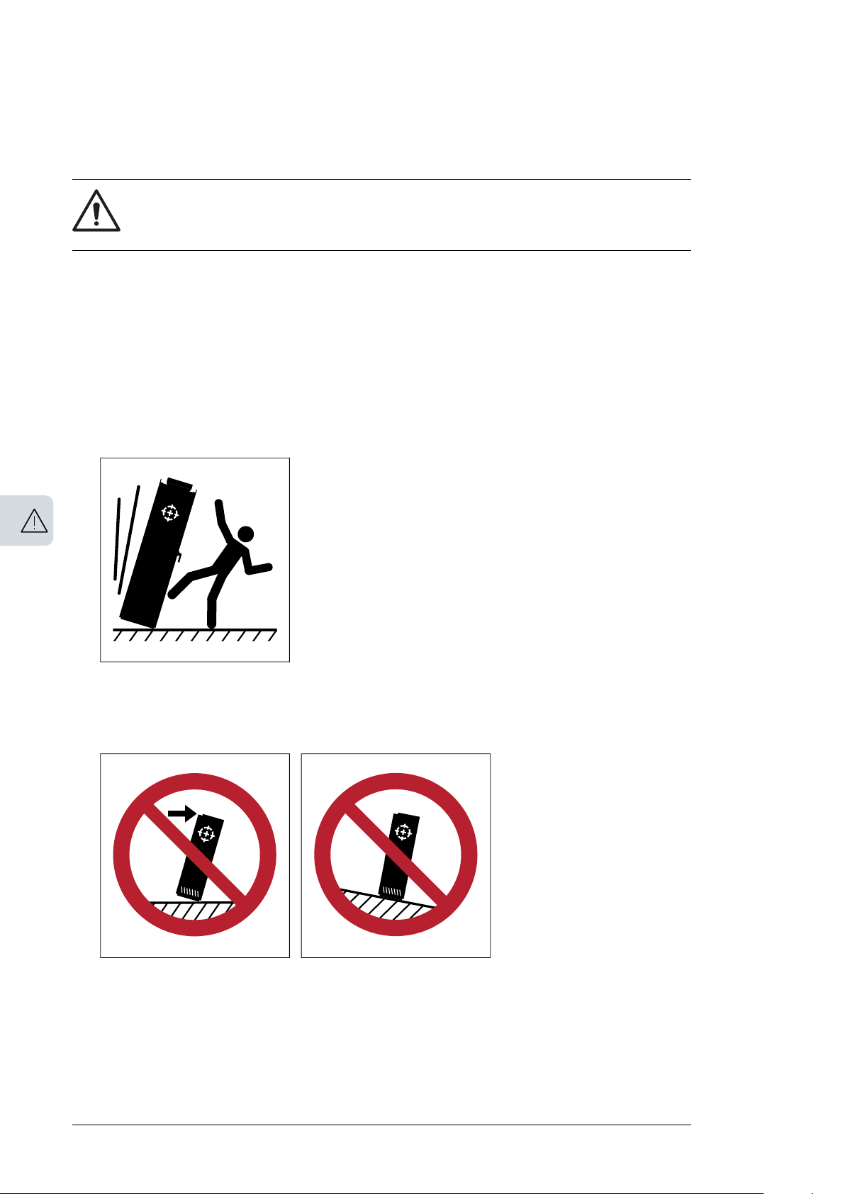
• Be careful when handling a tall module. The module overturns easily because it is heavy
and has a high center of gravity. Whenever possible, secure the module with chains.
Do not leave an unsupported module unattended especially on a sloping floor.
• Beware of hot surfaces. Some parts, such as heatsinks of power semiconductors, and
brake resistors, remain hot for a while after disconnection of the electrical supply.
• Make sure that there is sufficient cooling. See the technical data.
• Before you adjust the drive operation limits, make sure that the motor and all driven
equipment can operate throughout the set operation limits.

Safety instructions 13
• Before you activate the automatic fault reset or automatic restart functions of the drive
control program, make sure that no dangerous situations can occur. These functions
reset the drive automatically and continue operation after a fault or supply break. If these
functions are activated, the installation must be clearly marked as defined in IEC/EN
61800-5-1, subclause 6.5.3, for example, "THIS MACHINE STARTS AUTOMATICALLY".
• The maximum number of drive power-ups is five in ten minutes. Too frequent power-ups
can damage the charging circuit of the DC capacitors.
• Validate any safety circuits (for example, Safe torque off or emergency stop) in start-up.
See separate instructions for the safety circuits.
Note:
• If you select an external source for the start command and it is on, the drive will start
immediately after fault reset unless you configure the drive for pulse start. See the
firmware manual.
• Depending on the wiring and parametrization of the drive, the stop key on the control
panel may not stop the drive.
• Only authorized persons are allowed to repair a malfunctioning drive.
14 Safety instructions
Electrical safety in installation, start-up and maintenance
■ Electrical safety precautions
These electrical safety precautions are for all personnel who do work on the drive, motor
cable or motor.
WARNING!
Obey these instructions. If you ignore them, injury or death, or damage to the
equipment can occur. If you are not a qualified electrician, do not do installation
or maintenance work. Go through these steps before you begin any installation or
maintenance work.
1. Clearly identify the work location and equipment.
2. Disconnect all possible voltage sources. Lock and tag.
• Open the main disconnecting device of the drive.
• If you have a permanent magnet motor connected to the drive, disconnect the motor
from the drive with a safety switch or by other means.
• Make sure that re-connection is not possible.
• Disconnect any external power sources from the control circuits.
• After you disconnect the drive, always wait 5 minutes to let the intermediate circuit
capacitors discharge before you continue.
3. Protect any other energized parts in the work location against contact.
4. Take special precautions when close to bare conductors.
5. Measure that the installation is de-energized.
• Use a multimeter with an impedance of at least 1 Mohm.
• Make sure that the voltage between the drive input power terminals and the
grounding (PE) busbar is close to 0 V.
• If you have a permanent magnet motor connected to the drive, make sure that the
voltage between the drive output terminals and the grounding (PE) busbar is close
to 0 V.
6. Ask the person in control of the electrical installation work for a permit to work.
■ Additional instructions and notes
WARNING!
Obey these instructions. If you ignore them, injury or death, or damage to the
equipment can occur.
• If you are not a qualified electrician, do not do electrical installation or maintenance
work.
• Do not install the drive if the electrical power network, motor/generator, or environmental
conditions do not agree with the drive data.
• Do not do insulation or voltage withstand tests on the drive.
Note:
• The motor cable terminals of the drive are at a dangerous voltage when the input power
is on, regardless of whether the motor is running or not.
• When the input power is on, the drive DC bus is at a dangerous voltage.

Safety instructions 15
• External wiring can supply dangerous voltages to the relay outputs of the control units
of the drive.
• The Safe torque off function does not remove the voltage from the main and auxiliary
circuits. The function is not effective against deliberate sabotage or misuse.
Optical components
WARNING!
Obey these instructions. If you ignore them, damage to the equipment can occur.
• When you unplug the fibre optic cables, always hold the connector, not the cable itself.
• Do not touch the ends of the fibers with bare hands as the ends are extremely sensitive
to dirt.
• Do not bend the fiber optic cables too tightly. The minimum allowed bend radius is
35 mm (1.4”).
Printed circuit boards
WARNING!
Use a grounding wrist band when you handle printed circuit boards. Do not touch
the boards unnecessarily. The boards contain components sensitive to electrostatic
discharge.
■ Grounding
These instructions are for all personnel who are responsible for the grounding of the drive.
WARNING!
Obey these instructions. If you ignore them, injury or death, or equipment
malfunction can occur, and electromagnetic interference can increase.
• If you are not a qualified electrician, do not do grounding work.
• Always ground the drive, the motor and adjoining equipment. This is necessary for the
personnel safety. Proper grounding also reduces electromagnetic emission and
interference.
• Make sure that the conductivity of the protective earth PE conductors is sufficient. See
the electrical planning instructions of the drive. Obey the local regulations.
• Connect the power cable shields to protective earth terminals of the drive to make sure
of personnel safety.
• Make a 360° grounding of the power and control cable shields at the cable entries to
suppress electromagnetic disturbances.
• In a multiple-drive installation, connect each drive separately to the protective earth
(PE) busbar of the power supply.
Note:
• You can use power cable shields as grounding conductors only when their conductivity
is sufficient.
• IEC/EN 61800-5-1 (section 4.3.5.5.2.) requires that as the normal touch current of the
drive is higher than 3.5 mA AC or 10 mA DC, you must use a fixed protective earth (PE)
connection. The minimum size of the protective earthing conductor must comply with
the local safety regulations for high protective earthing conductor current equipment.

16 Safety instructions
See the electrical planning instructions of the drive, and standard IEC/EN 61800-5-1,
4.3.5.5.2.
Safety instructions 17
Additional instructions for permanent magnet motor drives
■ Safety in installation, start-up, maintenance
These are additional warnings concerning permanent magnet motor drives. The other safety
instructions in this chapter are also valid.
WARNING!
Obey these instructions. If you ignore them, injury or death and damage to the
equipment can occur.
• Do not do work on the drive when a rotating permanent magnet motor is connected to
it. A rotating permanent magnet motor energizes the drive including its input and output
power terminals.
Before installation, start-up and maintenance work on the drive:
•
Stop the drive and do the steps in section Electrical safety precautions (page 14).
• Disconnect the motor from the drive with a safety switch or by other means.
• If you cannot disconnect the motor, make sure that the motor cannot rotate during work.
Make sure that no other system, like hydraulic crawling drives, can rotate the motor
directly or through any mechanical connection like felt, nip, rope, etc.
• Measure that the installation is de-energized.
• Use a multimeter with an impedance of at least 1 Mohm.
• Make sure that the voltage between the drive output terminals and the grounding
(PE) busbar is close to 0 V.
• Make sure that the voltage between the drive input power terminals and the
grounding (PE) busbar is close to 0 V.
• Make sure that the voltage between the drive DC terminals (if any) and the grounding
(PE) terminal is close to 0 V.
• Install temporary grounding to the drive output terminals (U2, V2, W2). Connect the
output terminals together as well as to the PE.
During the start up:
• Make sure that the motor cannot be run into overspeed, eg, driven by the load. Motor
overspeed causes overvoltage that can damage or destroy the capacitors in the
intermediate circuit of the drive.
■ Safety in operation
WARNING!
Make sure that the motor cannot be run into overspeed, e.g. driven by the load.
Motor overspeed causes overvoltage that can damage or destroy the capacitors
in the intermediate circuit of the drive.

18

Introduction to the manual
Introduction to the manual 19
2
Contents of this chapter
The chapter describes applicability, target audience and purpose of this manual. It describes
the contents of this manual and refers to a list of related manuals for more information. The
chapter also contains a flowchart of steps for checking the delivery, installing and
commissioning the drive. The flowchart refers to chapters/sections in this manual.
Applicability
The manual applies to the ACQ80-04 drives.
Target audience
The reader is expected to know the fundamentals of electricity, wiring, electrical components
and electrical schematic symbols.
The manual is written for readers worldwide. Both SI and imperial units are shown. Special
US instructions for installations in the United States are given.
Purpose of the manual
This manual provides information needed for planning the installation, installing, and servicing
the drive.
Categorization by frame (size)
The ACQ80-04 is manufactured in frames (frame sizes) R0…R8. Some instructions and
other information which only concern certain frames are marked with the symbol of the
frame (R0…R8). The frame is marked on the type designation label attached to the drive,
see section Type designation label (page 34).

20 Introduction to the manual
Quick installation and commissioning flowchart
SeeTask
Identify the frame of your drive: R0…R8.
Plan the installation: select the cables, etc.
Check the ambient conditions, ratings and required cooling air flow.
Unpack and check the drive.
If the drive will be connected to an IT (ungrounded) system, check that the
internal EMC filter and ground-to-phase varistor are not connected. If the
drive will be connected to a corner-grounded TN system, check that the internal EMC filter is not connected.
Type designation label (page 34)
Planning the electrical installation (page 51)
Technical data (page 111)
Mechanical installation: Unpack-
ing and examining delivery,
frames R0…R2 (page 42), Unpacking and examining delivery,
frames R3...R4 (page 42), Unpacking and examining delivery,
frames R5 (page 43), Unpacking
and examining delivery, frames
R6…R8 (page 44).
Operation principle and hardware description: Type designa-
tion label (page 34)
Electrical installation: Checking
the compatibility with IT (ungrounded) and corner-grounded
TN systems (page 66)
Install the drive on a wall.
Route the cables.
Check the insulation of the input cable and the motor and the motor cable.
Connect the power cables.
Connect the control cables.
Check the installation.
Mechanical installation (page 39)
Planning the electrical installation: (page 57)
Electrical installation: Checking
the insulation of the assembly (page 65)
Electrical installation: Connect-
ing the power cables (page 70)
Electrical installation: Connect-
ing the control cables (page 84)
Installation checklist:Installation
checklist of the drive (page 99)

Introduction to the manual 21
SeeTask
Commission the drive
Terms and abbreviations
DescriptionTerm/
Abbreviation
Assistant control panelACS-AP-x
Basic control panelACS-BP-S
Optional I/O extension module underneath the fieldbus adapter moduleBIO-01
Circuit board in which the control program runsControl board
DC circuit between rectifier and inverterDC link
Energy storage which stabilizes the intermediate circuit DC voltageDC link capacit-
ors
Digital inputDI
Optional mounting platform for door mounting of control panelDPMP
Mounting platform for control panel (flush mounting)DPMP-01
Frequency converter for controlling AC motorsDrive
Embedded fieldbusEFB
Fieldbus adapterFBA
Optional CANopen adapter moduleFCAN
Optional EtherCAT adapter moduleFECA-01
Optional Ethernet adapter module for EtherNet/IP™, Modbus TCP and PROFINET IO protocolsFENA-11
FENA-21
size
circuit
Network control
Parameter
Optional Ethernet adapter module for EtherNet/IP™, Modbus TCP and PROFINET IO protocols,
2-port
Optional PROFIBUS DP adapter moduleFPBA-01
Physical size of the drive or power moduleFrame, frame
Optional RS-485 (Modbus/RTU) adapterFSCA-01
Insulated gate bipolar transistorIGBT
DC circuit between rectifier and inverterIntermediate
Converts direct current and voltage to alternating current and voltage.Inverter
A pre-defined set of default values of parameters in a drive control program.Macro
Remote monitoring toolNETA-21
With fieldbus protocols based on the Common Industrial Protocol (CIPTM), such as DeviceNet
and Ethernet/IP, denotes the control of the drive using the Net Ctrl and Net Ref objects of the
ODVA AC/DC Drive Profile. For more information, see www.odva.org.
In the drive control program, user-adjustable operation instruction to the drive, or signal
measured or calculated by the drive.
In some (for example fieldbus) contexts, a value that can be accessed as an object, eg, variable,
constant, or signal.
Programmable logic controllerPLC
Converts alternating current and voltage to direct current and voltageRectifier
Safe torque off (IEC/EN 61800-5-2)STO
ACQ80-04 standard control program firmware manual
(3AXD50000170654 [English])

22 Introduction to the manual
Related documents
Drive hardware manuals and guides
Code (English)Manual
ACQ80-04 standard control program firmware manual
ACQ80-04 (0.75 to 160 kW, 1.0 to 215 hp) hardware manual
ACQ80-04 drives quick installation and start-up guide
ACS-AP-x assistant control panels user’s manual
ACS-BP-S basic control panels user’s manual
Option manuals and guides
CPTC-02 ATEX-certified thermistor protection module, Ex II (2)
GD (+L537+Q971) user's manual
CDPI-0x communication adapter module user's manual
DPMP-01 mounting platform for ACS-AP control panel
DPMP-02/03 mounting platform for ACS-AP control panel
FCAN-01 CANopen adapter module user's manual
FCNA-01 ControlNet adapter module user's manual
FDNA-01 DeviceNet™ adapter module user's manual
FECA-01 EtherCAT adapter module user's manual
3AXD50000170654
3AXD50000170661
3AXD50000170647
3AUA0000085685
3AXD50000032527
3AXD50000032016
3AXD50000009929
3AUA0000100140
3AUA0000136205
3AFE68615500
3AUA0000141650
3AFE68573360
3AUA0000068940
FENA-01/-11/-21 Ethernet adapter module user's manual
FPBA-01 PROFIBUS DP adapter module user's manual
FSCA-01 RS-485 adapter module user's manual
Flange mounting kit installation supplement
Flange mounting kit quick installation guide for ACX580-01 frames
R0 to R5
Flange mounting kit quick installation guide for ACS880-01 and
ACX580-01 frames R6 to R8
Tool and maintenance manuals and guides
Drive composer PC tool user's manual
Converter module capacitor reforming instructions
NETA-21 remote monitoring tool user's manual
NETA-21 remote monitoring tool installation and startup guide
3AUA0000093568
3AFE68573271
3AUA0000109533
3AXD50000019100
3AXD50000036610
3AXD50000019099
3AUA0000094606
3BFE64059629
3AUA00000969391
3AUA0000096881
You can find manuals and other product documents in PDF format on the Internet. See
section Document library on the Internet on the inside of the back cover. For manuals not
available in the Document library, contact your local ABB representative.

Introduction to the manual 23
ACQ80-04 manuals
See www.abb.com/drives/documents for all manuals on the internet.

24

Operation principle and hardware description 25
3
Operation principle and hardware description
Contents of this chapter
This chapter briefly describes the operation principle, layout, type designation label and
type designation information. It also shows a general diagram of power connections and
control interfaces.
Operation principle
The ACQ80-04 is a drive for controlling asynchronous AC induction motors and permanent
magnet motors.

L1
L2
L3
T1/U
T2/V
T3/W
1 2 3
26 Operation principle and hardware description
The figure below shows the simplified main circuit diagram of the drive.
Rectifier. Converts alternating current and voltage to direct current and voltage.1
DC link. DC circuit between rectifier and inverter.2
Inverter. Converts direct current and voltage to alternating current and voltage.3
UDC-, UDC+ in frames R0…R2 and R-, UDC+ in frame R34
DC connection (UDC+, UDC-) in frames R4…R8.5
Layout
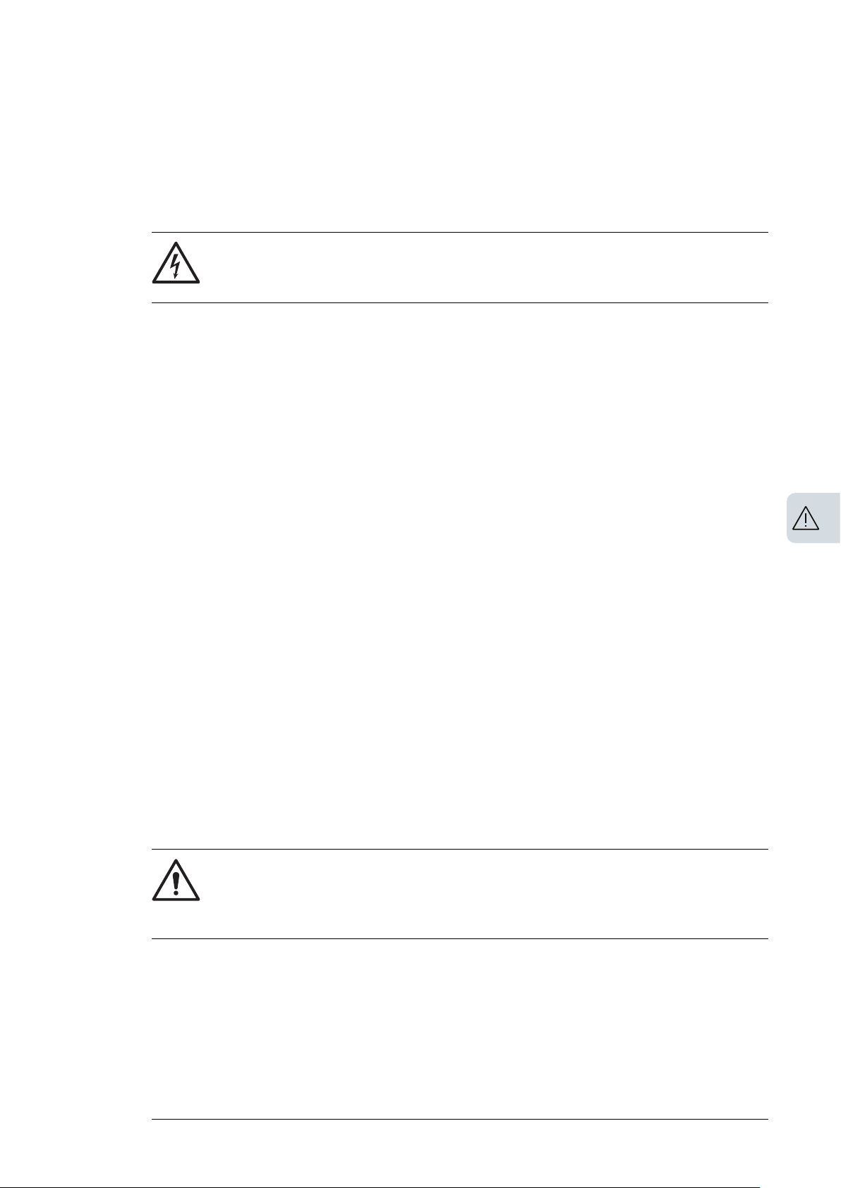
■ Frames R0...R2
The layout of a frame R0 drive is presented below. The frame sizes R1…R2 is similar to
R0 but have a different structure.
7
10
8
9
13
6
16
11
14
15
1
7
12
1
1
3
2
1
4
5
Installation point (4)1
Cover plate2
Cover plate screw3
Control panel4
Control panel connection5
CCA-01 interface6
7
For LED of normal power supply and failure, see
section LEDs (page 108).
8
I/O connection. See section External control
connecting terminal, Frame size
R0…R2 (page 30).
Voltage dependent resistor grounding screw
9
(VAR)
Operation principle and hardware description 27
EMC filter grounding screw (EMC).
10
R0…R2: on the left side of drive.
Input voltage connection (L1, L2, L3).11
Motor connection (T1/U, T2/V, T3/W) and PV
12
input terminal connection (UDC+, UDC-).
PE connection (power line)13
Earthing connection (motor)14
Other earthing connections15
Fan16
Cable bundle installation position of I/O cable17
1
1
4
2
1
3
14
10
9
8
7
12
11
13
5
6
28 Operation principle and hardware description
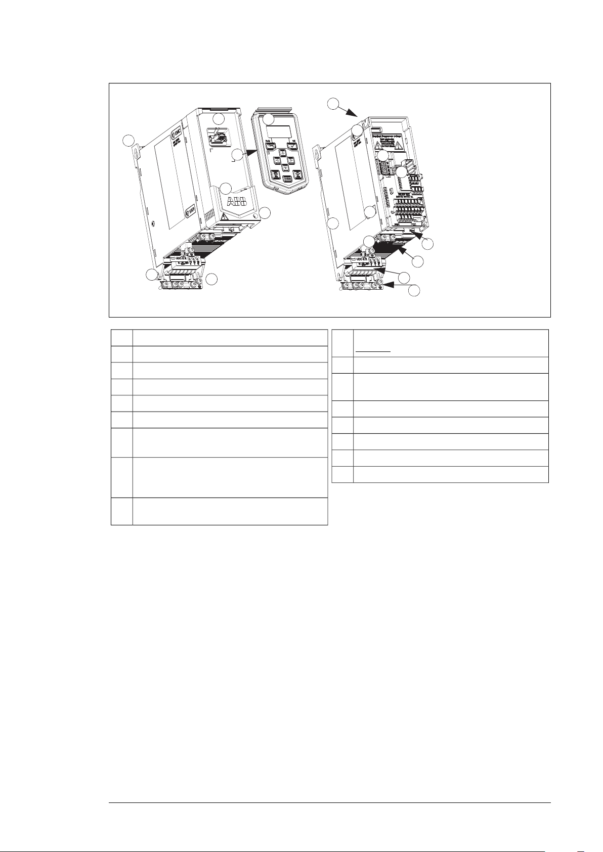
■ Frame size R3
Installation point (4)1
Cover plate2
Cover plate screw3
Control panel4
Control panel connection5
CCA-01 interface6
7
For LED of normal power supply and failure, see
EMC filter grounding screw (EMC).10
Input voltage connection (L1, L2, L3), motor
11
connection (T1/U, T2/V, T3/W) and PV input
terminal connection (R-, UDC+).
PE connection (power line)12
Earthing connection (motor)13
Fan14
section LEDs (page 108).
8
I/O connection. See section External control
connecting terminal, Frame size
R3...R5 (page 31).
Voltage dependent resistor grounding screw
9
(VAR)
2
3
4
5
6
7
8
11
12
13
10
10
3
16
15
1
9
12
17
14
1
Operation principle and hardware description 29
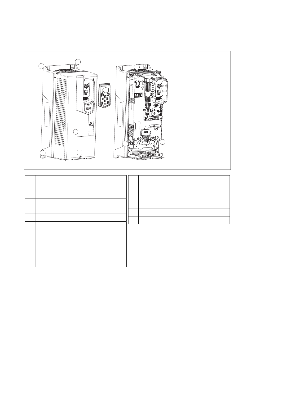
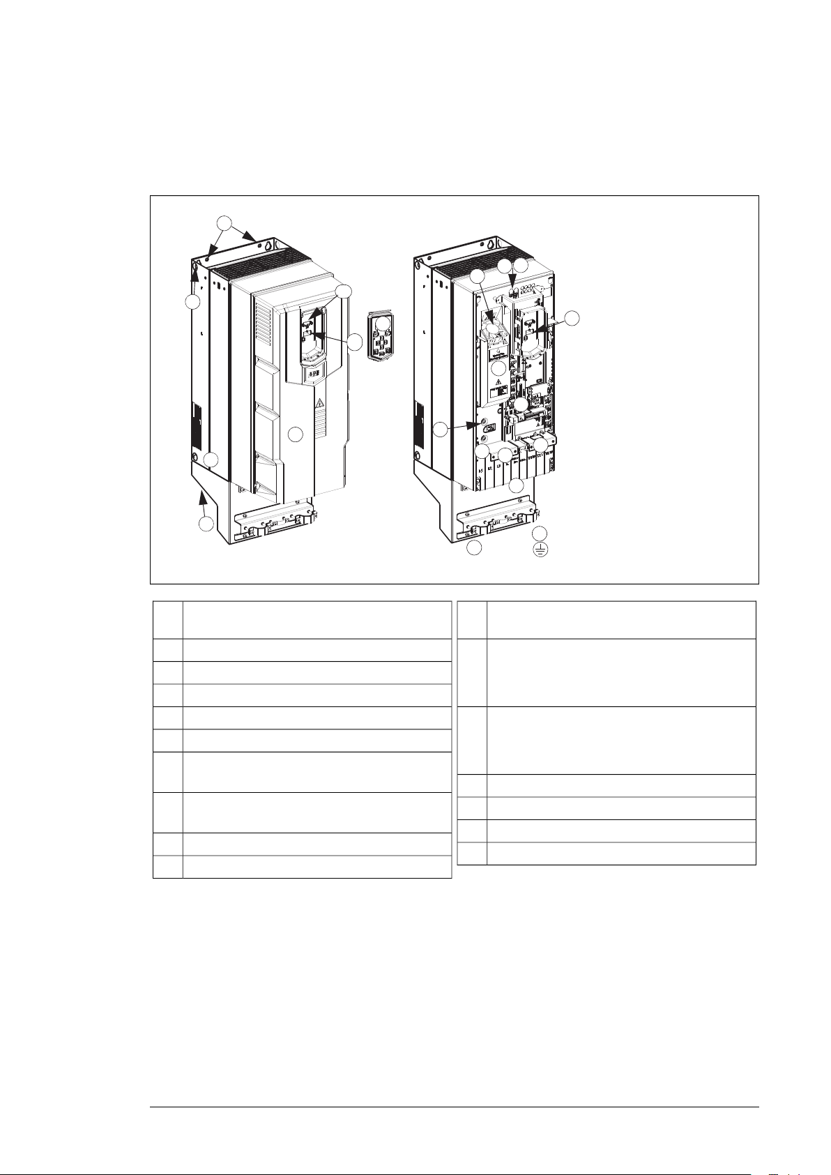
■ Frame R4…R8
The layout of a frame R6 drive is presented below. The frame sizes R7…R8 is similar but
have a different structure.
Voltage dependent resistor ground screw (VAR),
Installation point (2 points on the top and 2 points
1
on the bottom of the frame body)
Cover plate2
Lifting hole3
Basic control panel4
Control panel connection5
CCA-01 interface6
7
For LED of normal power supply and failure, see
section LEDs (page 108).
8
I/O connection. See section External control
connection terminals, frames R6…R8 (page 32).
Cable bundle installation position of I/O cable9
Mechanical support clamp of I/O cable10
Overview of power and control connections
The logical diagram below shows the power connections and control interfaces of the drive.
11
arranged below the control tray.
Two EMC filter ground screws, one arranged
12
below the control tray bracket and the other arranged on the left and above the protective cover.
Protective cover. Below the protective cover: in-
13
put voltage connection (L1, L2, L3), motor connection (T1/U, T2/V, T3/W) and DC connection
(UDC+, UDC-).
PE connection (power line)14
Earthing connection (motor)15
A primary fan16
Auxiliary fan17

X1A
X1B
X1C X1D X5
X11 X3B X3C
X8
X7
X
2
X4A
X3A
X4B
X
6
1
30 Operation principle and hardware description
■ External control connecting terminal, Frame size R0…R2
The figure below explains the external control connecting terminal layout of Frame size R0.
Layout of the external control connection terminals is identical in frames R1…R2 but the
location of the control board with the terminals is different in frames R3.
R0...R2
Description
Analog input and outputX1 A…D
Auxiliary voltage outputX2
Digital signal inputX3 A…C
Safety torque cancellationX4 A…B
Modbus built-in fieldbusX5
Relay 1 outputX6…X8
+24V DC voltage outputX11
1
The interface is used for CCA-01
adapter configuration
 Loading...