

Page 1

SIP
IP
PHONE
53i, 55i, 57i, 57i C
53i, 55i, 57i, 57i CT
SI
I
PHONE
41-001160-00
Rev 04
Administrator Guide
Release 2.1
Page 2

Aastra Telecom will not accept liability for any damages and/or long distance charges, which result from
unauthorized and/or unlawful use. While every effort has been made to ensure accuracy, Aastra Telecom will
not be liable for technical or editorial errors or omissions contained within this documentation. The
information contained in this documentation is subject to change without notice.
Copyright 2007 Aastra Telecom. www.aastratelecom.com
All Rights Reserved.
Page 3

Software License Agreement
Aastra Telecom Inc., hereinafter known as "Seller", grants to Customer a
personal, worldwide, non-transferable, non-sublicenseable and non-exclusive,
restricted use license to use Software in object form solely with the Equipment for
which the Software was intended. This Product may integrate programs, licensed
to Aastra by third party Suppliers, for distribution under the terms of this
agreement. These programs are confidential and proprietary, and are protected as
such by copyright law as unpublished works and by international treaties to the
fullest extent under the applicable law of the jurisdiction of the Customer. In
addition, these confidential and proprietary programs are works conforming to the
requirements of Section 401 of title 17 of the United States Code. Customer shall
not disclose to any third party such confidential and proprietary programs and
information and shall not export licensed Software to any country except in
accordance with United States Export laws and restrictions.
Customer agrees to not reverse engineer, decompile, disassemble or display
Software furnished in object code form. Customer shall not modify, copy,
reproduce, distribute, transcribe, translate or reduce to electronic medium or
machine readable form or language, derive source code without the express
written consent of the Seller and its Suppliers, or disseminate or otherwise
disclose the Software to third parties. All Software furnished hereunder (whether
or not part of firmware), including all copies thereof, are and shall remain the
property of Seller and its Suppliers and are subject to the terms and conditions of
this agreement. All rights reserved.
Customer's use of this software shall be deemed to reflect Customer's agreement
to abide by the terms and conditions contained herein. Removal or modification
of trademarks, copyright notices, logos, etc., or the use of Software on any
Equipment other than that for which it is intended, or any other material breach of
this Agreement, shall automatically terminate this license. If this Agreement is
terminated for breach, Customer shall immediately discontinue use and destroy or
return to Seller all licensed software and other confidential or proprietary
information of Seller. In no event shall Seller or its suppliers or licensors be liable
for any damages whatsoever (including without limitation, damages for loss of
business profits, business interruption, loss of business information, other
pecuniary loss, or consequential damages) arising out of the use of or inability to
use the software, even if Seller has been advised of the possibility of such
damages.
41-001160-00, Release 2.1, Rev 04 iii
Page 4

Page 5

Contents
Preface
About this guide ...............................................................................................................xiii
Introduction ...............................................................................................................xiii.
Audience ...................................................................................................................xiii.
Other Documentation ............................................................................................... xiv.
Chapters and appendixes in this guide ..................................................................... xv.
Chapter 1
Overview
.
About this chapter ...........................................................................................................1-1.
IP Phone Models ............................................................................................................1-2.
Description ...............................................................................................................1-2.
Model 53i IP Phone ..................................................................................................1-5.
Model 55i IP Phone ..................................................................................................1-8.
Model 57i and 57i CT IP Phone .............................................................................1-12.
Firmware Installation Information .................................................................................1-18.
Description .............................................................................................................1-18.
Installation Considerations .....................................................................................1-18.
Installation Requirements .......................................................................................1-19.
Configuration Server Requirement .........................................................................1-20.
Firmware and Configuration Files .................................................................................1-21.
Description .............................................................................................................1-21.
Configuration File Precedence ...............................................................................1-22.
Installing the Firmware/Configuration Files ............................................................1-23.
Contents
.
41-001160-00, Release 2.1 Rev 04 v
Page 6

Chapter 2
Configuration Interface Methods
About this chapter ...........................................................................................................2-1.
Configuration Methods ...................................................................................................2-2.
Contents
Chapter 3
Administrator Options
About this chapter ...........................................................................................................3-1.
Administrator Level Options ...........................................................................................3-3.
.
Description ...............................................................................................................2-2.
IP Phone UI ..............................................................................................................2-2.
Aastra Web UI ..........................................................................................................2-5.
Configuration Files (Administrator Only) ................................................................2-15.
.
Description ...............................................................................................................3-3.
IP Phone UI Options ................................................................................................3-3.
Aastra Web UI Options ............................................................................................3-7.
Configuration File Options ........................................................................................3-9.
Phone Status ..........................................................................................................3-10.
Restarting Your Phone ...........................................................................................3-13.
Set Phone to Factory Defaults/Erase Local Configuration .....................................3-15.
Basic Settings ........................................................................................................3-19.
Network Settings ....................................................................................................3-31.
Line Settings ..........................................................................................................3-56.
Softkeys, Programmable Keys, Expansion Module Keys ......................................3-57.
Action URI ..............................................................................................................3-58.
Configuration Server Settings ................................................................................3-59.
Firmware Update Features ....................................................................................3-66.
vi 41-001160-00, Release 2.1 Rev 04
Page 7

Chapter 4
Configuring Network and
Session Initiation Protocol (SIP) Features
.
About this chapter ...........................................................................................................4-1.
Overview .........................................................................................................................4-3.
Network Settings ............................................................................................................4-4.
Basic Network Settings ............................................................................................4-4.
Advanced Network Settings ...................................................................................4-16.
Global SIP Settings ......................................................................................................4-44.
Description .............................................................................................................4-44.
Basic SIP Settings ..................................................................................................4-45.
Advanced SIP Settings (optional) ..........................................................................4-57.
Real-time Transport Protocol (RTP) Settings .........................................................4-63.
Autodial Settings ....................................................................................................4-73.
Configuration Server Protocol ......................................................................................4-78.
Configuring the Configuration Server Protocol .......................................................4-78.
Chapter 5
Configuring Operational Features
.
About this chapter ...........................................................................................................5-1.
Operational Features ......................................................................................................5-4.
Description ...............................................................................................................5-4.
User Passwords .......................................................................................................5-4.
Administrator Passwords .........................................................................................5-8.
Locking/Unlocking the Phone ...................................................................................5-9.
Defining an Emergency Dial Plan ..........................................................................5-15.
Time and Date ........................................................................................................5-17.
Language ...............................................................................................................5-21.
Locking IP Phone Keys ..........................................................................................5-28.
Local Dial Plan .......................................................................................................5-30.
Park Calls/Pick Up Parked Calls ............................................................................5-35.
Suppressing DTMF Playback .................................................................................5-39.
Display DTMF Digits ..............................................................................................5-41.
Call Waiting/Call Waiting Tone ...............................................................................5-43.
Stuttered Dial Tone .................................................................................................5-46.
Contents
41-001160-00, Release 2.1 Rev 04 vii
Page 8

Contents
XML Beep Support .................................................................................................5-48.
Status Scroll Delay .................................................................................................5-50.
Incoming Call Interrupts Dialing .............................................................................5-52.
Goodbye Key Cancels Incoming Call .....................................................................5-54.
UPnP Mapping Lines (for remote phones) .............................................................5-56.
Message Waiting Indicator Line .............................................................................5-58.
Incoming/Outgoing Intercom with Auto-Answer and Barge In ...............................5-60.
Key Mapping ..........................................................................................................5-66.
Ring Tones and Tone Sets .....................................................................................5-70.
Priority Alerting .......................................................................................................5-75.
Directed Call Pickup (BLF or XML Call Interception) .............................................5-81.
Softkeys/Programmable Keys/Feature Keys/Expansion Module Keys ..................5-93.
Speeddial Prefixes ...............................................................................................5-113.
Busy Lamp Field (BLF) ........................................................................................5-114.
BLF Subscription Period ......................................................................................5-120.
Automatic Call Distribution (ACD) (for Sylantro Servers) .....................................5-122.
ACD Subscription Period .....................................................................................5-133.
Directed Call Pickup/Group Call Pickup (for Sylantro Servers) ............................5-135.
Do Not Disturb (DND) ..........................................................................................5-142.
Bridged Line Appearance (BLA) (55i, 57i, 57i CT only) .......................................5-144.
BLA Support for Third Party Registration .............................................................5-151.
Park/Pick Up Key .................................................................................................5-153.
Last Call Return (lcr) (For Sylantro Servers .........................................................5-164.
Call Forwarding ....................................................................................................5-168.
Callers List ...........................................................................................................5-174.
Customizable Callers List and Services Keys ......................................................5-179.
Missed Calls Indicator ..........................................................................................5-180.
Directory List ........................................................................................................5-182.
Voicemail (55i, 57i, and 57i CT only) ....................................................................5-193.
XML Customized Services ...................................................................................5-196.
Audio Transmit and Receive Gain Adjustments ...................................................5-218.
Centralized Conferencing (for Sylantro and Broadsoft Servers) ..........................5-220.
Customizing the Display Columns on the 560M Expansion Module ....................5-224.
viii 41-001160-00, Release 2.1 Rev 04
Page 9

Chapter 6
Configuring Advanced Operational Features
.
About this chapter ...........................................................................................................6-1.
Advanced Operational Features .....................................................................................6-3.
Description ...............................................................................................................6-3.
MAC Address/Line Number in REGISTER Messages .............................................6-5.
SIP Message Sequence for Blind Transfer ..............................................................6-7.
Update Caller ID During a Call .................................................................................6-8.
Boot Sequence Recovery Mode ..............................................................................6-9.
Auto-discovery Using mDNS ..................................................................................6-10.
Single Call Restriction (57i CT only) ......................................................................6-11.
Missed Call Summary Subscription .......................................................................6-13.
Blacklist Duration (Broadsoft Servers) ...................................................................6-17.
Whitelist Proxy .......................................................................................................6-19.
Transport Layer Security (TLS) ..............................................................................6-21.
Symmetric UDP Signaling ......................................................................................6-27.
Removing UserAgent and Server SIP Headers .....................................................6-28.
Multi-Stage Digit Collection (Billing Codes) Support (for Sylantro Servers) ...........6-29.
Chapter 7
Encrypted Files on the IP Phone
.
About this chapter ...........................................................................................................7-1.
Encrypted Files on the IP Phone ....................................................................................7-2.
Configuration File Encryption Method ......................................................................7-2.
Procedure to Encrypt/Decrypt Configuration Files ...................................................7-3.
Contents
Chapter 8
Upgrading the Firmware
.
About this chapter ...........................................................................................................8-1.
Upgrading the Firmware .................................................................................................8-2.
Manual Firmware Update (TFTP only) .....................................................................8-2.
Manual Firmware and Configuration File Update .....................................................8-4.
Automatic Update (auto-resync) ..............................................................................8-6.
......................................................................................................................................8-10.
41-001160-00, Release 2.1 Rev 04 ix
Page 10

Chapter 9
Troubleshooting
About this chapter ...........................................................................................................9-1.
Troubleshooting ..............................................................................................................9-2.
Contents
Troubleshooting Solutions ..............................................................................................9-7.
Appendix A
Configuration Parameters
About this appendix ....................................................................................................... A-1.
Setting Parameters in Configuration Files ..................................................................... A-4.
Operational, Basic, and Advanced Parameters ............................................................. A-5.
.
Description ...............................................................................................................9-7.
Why does my phone display “Application missing”? ................................................9-7.
Why does my phone display the “No Service” message? ........................................9-8.
Why does my phone display "Bad Encrypted Config"? ............................................9-8.
Why is my phone not receiving the TFTP IP address from the DHCP Server? .......9-9.
How do I restart the IP phone? ..............................................................................9-10.
How do I set the IP phone to factory default? ........................................................9-11.
How do I erase the phone’s local configuration? ...................................................9-12.
How to reset a user’s password? ...........................................................................9-13.
How do I lock and unlock the phone? ....................................................................9-14.
.
Simplified IP Phone UI Options Menu ..................................................................... A-5.
Network Settings ..................................................................................................... A-6.
Password Settings .................................................................................................. A-9.
Emergency Dial Plan Settings ............................................................................... A-11.
Aastra Web UI Settings ......................................................................................... A-12.
Configuration Server Settings ............................................................................... A-13.
Network Address Translation (NAT) Settings ........................................................ A-20.
HTTPS Client and Server Settings ........................................................................ A-23.
UPnP Settings ....................................................................................................... A-25.
Virtual Local Area Network (VLAN) Settings ......................................................... A-26.
Type of Service (ToS)/DSCP Settings ................................................................... A-30.
Time Server Settings ............................................................................................. A-31.
Time and Date Settings ......................................................................................... A-33.
SIP Local Dial Plan Settings ................................................................................. A-39.
x 41-001160-00, Release 2.1 Rev 04
Page 11

SIP Basic, Global Settings .................................................................................... A-41.
SIP Basic, Per-Line Settings ................................................................................. A-50.
Centralized Conferencing Settings ........................................................................ A-60.
Advanced SIP Settings ......................................................................................... A-62.
Missed Call Summary Subscription Settings ........................................................ A-70.
Transport Layer Security (TLS) Settings ............................................................... A-72.
RTP, Codec, DTMF Global Settings ...................................................................... A-77.
Autodial Settings ................................................................................................... A-81.
Voicemail Settings ................................................................................................. A-84.
Directory Settings .................................................................................................. A-85.
Callers List Settings .............................................................................................. A-86.
Customize Callers List and Services Key ............................................................. A-86.
Call Forward Settings ............................................................................................ A-87.
Missed Calls Indicator Settings ............................................................................. A-88.
XML Settings ......................................................................................................... A-89.
Action URI Settings ............................................................................................... A-92.
Ring Tone and Tone Set Global Settings .............................................................. A-94.
Ring Tone Per-Line Settings ................................................................................. A-97.
Incoming Call Interrupts Dialing Setting ................................................................ A-98.
Goodbye Key Cancels Incoming Call .................................................................... A-99.
Stuttered Dial Tone Setting ................................................................................. A-100.
Call Waiting Settings ........................................................................................... A-101.
Message Waiting Indicator Settings .................................................................... A-102.
Priority Alert Settings ........................................................................................... A-103.
Language Settings .............................................................................................. A-109.
Language Pack Settings ..................................................................................... A-110.
Suppress DTMF Playback Setting ...................................................................... A-119.
Display DTMF Digits Setting ............................................................................... A-120.
Intercom, Auto-Answer, and Barge In Settings ................................................... A-121.
Audio Transmit and Receive Gain Adjustment Settings ..................................... A-125.
Directed Call Pickup (BLF or XML Call Interception) Settings ............................ A-128.
ACD Auto-Available Timer Settings ................................................................... A-131.
Park and Pickup Global Settings (57i/57i CT only) ............................................. A-132.
Mapping Key Parameters .................................................................................... A-133.
Contents
41-001160-00, Release 2.1 Rev 04 xi
Page 12

Softkey/Programmable Key/Feature Key/Expansion Module Key Parameters ......... A-136.
Contents
Customizing 560M Expansion Module Column Display ............................................ A-166.
Advanced Operational Parameters ........................................................................... A-172.
Troubleshooting Parameters ..................................................................................... A-177.
Softkey Settings for 55i, 57i, 57i CT .................................................................... A-137.
Programmable Key Settings for 53i and 55i ........................................................ A-145.
Top Softkey Settings for 57i and 57i CT .............................................................. A-150.
Handset Feature Key Settings for the 57i CT ..................................................... A-156.
Expansion Module Key Settings for 536M (for all model phones)
and 560M (for 55i, 57i, 57i CT phones only) ....................................................... A-158
Locking Softkeys and Programmable Keys ........................................................ A-163.
Expansion Module 1 ............................................................................................ A-166.
Expansion Module 2 ............................................................................................ A-168.
Expansion Module 3 ............................................................................................ A-170.
Blind Transfer Setting .......................................................................................... A-172.
Update Caller ID Setting. .................................................................................... A-173.
Boot Sequence Recovery Mode. ........................................................................ A-173.
Single Call Restriction ......................................................................................... A-174.
Blacklist Duration ................................................................................................ A-175.
Whitelist Proxy .................................................................................................... A-175.
Symmetric UDP Signaling Setting ....................................................................... A-176.
User-Agent Setting .............................................................................................. A-176.
Log Settings ........................................................................................................ A-177.
.
Appendix B
Configuration Server Setup
.
About this appendix ....................................................................................................... B-1.
Configuration Server Protocol Setup ............................................................................. B-2.
TFTP Server Set-up ................................................................................................ B-2.
Appendix C
Configuring the IP Phone at the Asterisk IP PBX
.
About this appendix ....................................................................................................... C-1.
IP Phone at the Asterisk IP PBX ...................................................................................C-2.
xii 41-001160-00, Release 2.1 Rev 04
Page 13

Appendix D
Sample Configuration Files
.
About this appendix ....................................................................................................... D-1.
Sample Configuration Files ...........................................................................................D-2.
57i Sample Configuration File .................................................................................D-2.
57i CT Sample Configuration File ......................................................................... D-12.
53i Sample Configuration File ............................................................................... D-29.
Appendix E
Sample BLF Softkey Settings
.
About this appendix ....................................................................................................... E-1.
Sample BLF Softkey Settings ........................................................................................ E-2.
Asterisk BLF ............................................................................................................ E-2.
BroadSoft BroadWorks BLF .................................................................................... E-3.
Appendix F
Sample Multiple Proxy Server Configuration
.
About this appendix ....................................................................................................... F-1.
Multiple Proxy Server Configuration .............................................................................. F-2.
Appendix G
Creating an XML Application
.
About this appendix .......................................................................................................G-1.
How to Create an XML Application ................................................................................G-3.
Overview .................................................................................................................G-3.
XML format ..............................................................................................................G-3.
Support of Virtual Web Servers ...............................................................................G-3.
Creating XML Objects .............................................................................................G-4.
Creating Custom Softkeys ......................................................................................G-5.
Text Menu Object (Menu Screens) ..........................................................................G-6.
Text Screen Object (Text Screens) ........................................................................G-12.
UserInput Object (User Input Screens) .................................................................G-21.
Directory Object (Directory List Screen) (57i only) ................................................G-36.
Status Message Object (Idle Screen) ....................................................................G-38.
Execute Commands Object (for executing XML commands) ...............................G-40.
Dynamic Configuration Object (to push a configuration to the phone) ..................G-44.
Contents
41-001160-00, Release 2.1 Rev 04 xiii
Page 14

XML Image Objects (55i, 57i/57i CT only) ............................................................G-48.
Attributes/Options to Use with XML Objects .........................................................G-58.
HTTP Post .............................................................................................................G-62.
XML Schema File ..................................................................................................G-65.
Contents
Limited Warranty
.
xiv 41-001160-00, Release 2.1 Rev 04
Page 15

About this guide
Introduction
This SIP IP Phone Administrator Guide provides information on the basic
network setup, operation, and maintenance of the IP phones, Models 53i, 55i, 57i,
and 57i Cordless (57i CT). It also includes details on the functioning and
configuration of the IP phones.
Note: Features, characteristics, requirements, and configuration that are
specific to a particular IP phone model are indicated where required in
this guide.
Audience
Preface
Preface
This guide is for network administrators, system administrators, developers and
partners who need to understand how to operate and maintain the IP phone on a
SIP network. It also provides some user-specific information.
This guide contains information that is at a technical level, more suitable for
system or network administrators. Prior knowledge of IP Telephony concepts is
recommended.
41-001160-00, Release 2.1, Rev 04 xiii
Page 16

IP Phone Administrator Guide
About this guide
Other Documentation
The IP phone documentation consists of:
• <Model-specific> SIP IP Phone Installation Guide – contains installation
and set-up instructions, information on general features and functions, and
basic options list customization. Included with the phone.
Preface
• Model 53i, 55i, 57i, 57i CT SIP IP Phone Administrator Guide – explains
• <Model-specific> SIP IP Phone User Guides – explains the most commonly
This Administrator Guide complements the Aastra product-specific Installation
Guide and the Aastra product-specific User Guide.
how to set the phone up on the network, as well as advanced configuration
instructions for the SIP IP phone. This guide contains information that is at a
technical level more suitable for a system or network administrator.
used features and functions for an end user.
xiv 41-001160-00, Release 2.1, Rev 04
Page 17

Chapters and appendixes in this guide
This guide contains the following chapters and appendixes:
For Go to
An overview of the IP Phone firmware installation information Chapter 1
IP Phone interface methods Chapter 2
Administrator option information Chapter 3
Configuring the Network and Global SIP Features on the IP Phone Chapter 4
Configuring operational information on the IP Phones Chapter 5
Configuring advanced operational information on the IP Phones Chapter 6
Encryption information Chapter 7
Firmware upgrade information Chapter 8
Troubleshooting solutions Chapter 9
Configuration parameters Appendix A
Configuration server setup Appendix B
Configuring the IP Phones at the Asterisk PBX Appendix C
Sample configuration files Appendix D
Sample BLF softkey settings Appendix E
Sample multiple proxy server configuration Appendix F
Creating XML applications Appendix G
Preface
41-001160-00, Release 2.1, Rev 04 xv
Page 18

Page 19

About this chapter
Introduction
This chapter briefly describes the IP Phone Models, and provides information
about installing the IP phone firmware. It also describes the firmware and
configuration files that the IP phone models use for operation.
Topics
This chapter covers the following topics:
Chapter 1
Overview
Overview
Topi c Page
IP Phone Models page 1-2
Firmware Installation Information page 1-18
Firmware and Configuration Files page 1-21
41-001160-00, Release 2.1, Rev 04 1-1
Page 20
IP Phone Administrator Guide
IP Phone Models
IP Phone Models
Description
The IP Phone Models 53i, 55i, 57i, and 57i CT communicate over an IP network
allowing you to receive and place calls in the same manner as a regular business
telephone.
Overview
All phone models support the Session Initiation Protocol (SIP). The 57i CT offers
the base phone along with a cordless extension.
References
For more information about the features and installation requirements, see the
SIP IP Phone Installation Guide for your specific model.
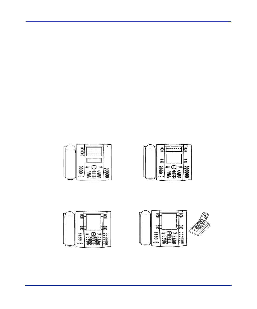
The following illustration shows the types of IP Phone Models.
53i
55i
57i
1-2 41-001160-00, Release 2.1, Rev 04
57i CT
Page 21

Overview
IP Phone Models
Optional Accessories
Overview
The following are optional accessories for the IP Phones.
Power over Ethernet (PoE)
Inline Power Injector
A Power over Ethernet (PoE) inline power injector supplies 48V power to the IP
phone through the Ethernet cable on pins 4 & 5 and 7 & 8.
Warning: Do not use this inline PoE power injector to power other
devices. See your phone-specific Installation Guide for more information.
Reference
For more information about installing the PoE and additional Ethernet cable, see
your phone-specific Installation Guide.
Additional Ethernet Cable
(category 5/5e straight through
cable)
41-001160-00, Release 2.1, Rev 04 1-3
Page 22

IP Phone Administrator Guide
IP Phone Models
Overview
536M Expansion Module
for 53i, 55i, 57i, and 57i CT
The 536M module adds 36 additional softkeys to the IP phone models 53i, 55i,
57i, and 57i CT. The 536M provides paper labels for each softkey. Up to 3
modules can be piggy-backed to provide up to 108 additional softkeys for the
phone.
The 560M module adds 60 additional softkeys to the IP phone models 55i, 57i,
and 57i CT (using the 3 function keys on the bottom right of the unit). The 560M
module provides an LCD display for display softkey labels. Up to 3 modules can
be piggy-backed to provide up to 180 additional softkeys for the phone.
Reference
For more information about installing and using the expansion modules, see your
phone-specific Installation Guide and phone-specific User Guide.
560M Expansion Module
for 55i, 57i, and 57i CT
1-4 41-001160-00, Release 2.1, Rev 04
Page 23
Overview
IP Phone Models
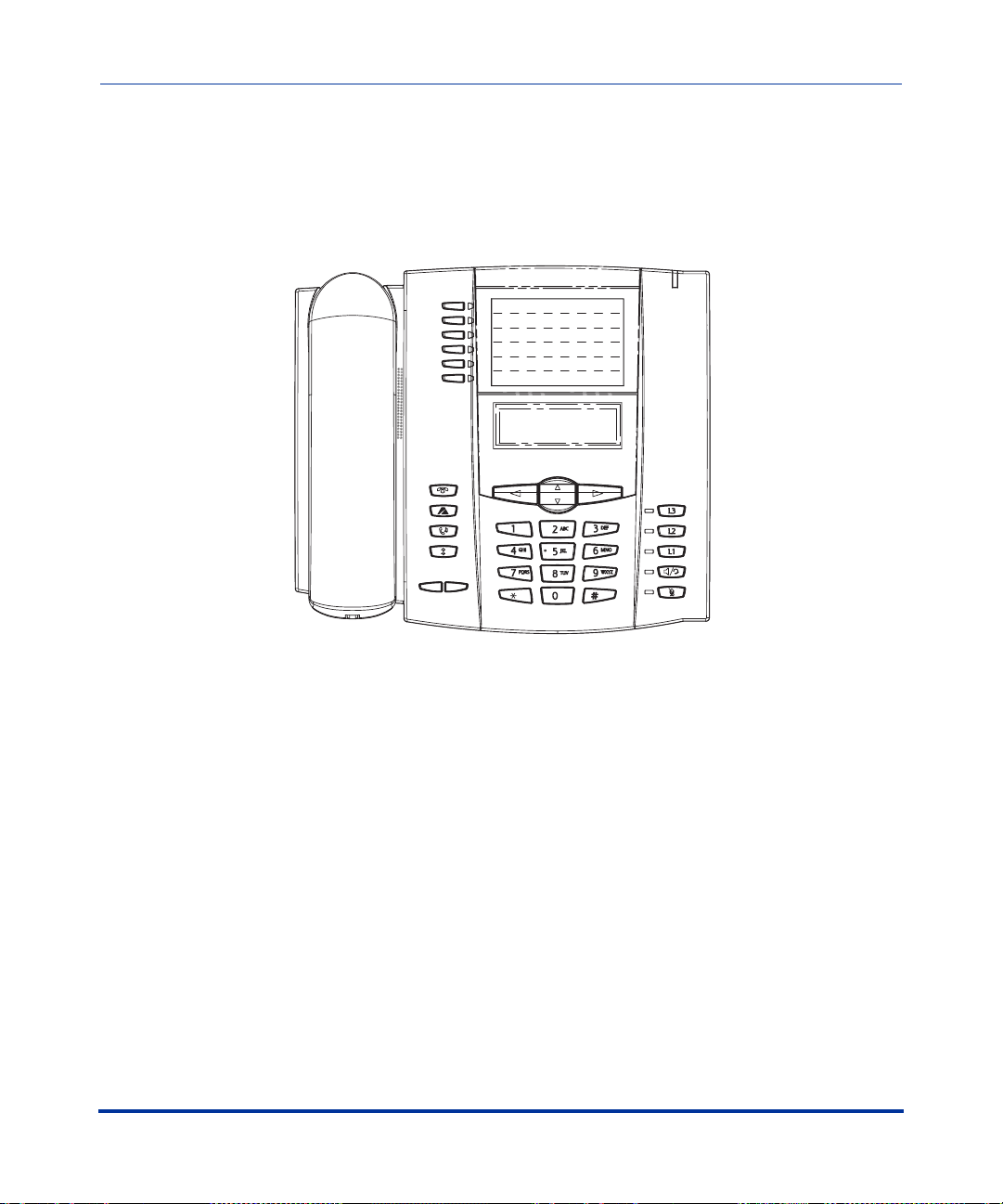
Model 53i IP Phone
This section provides brief information about the Model 53i IP Phone. It includes
a list of features, and describes the hard keys and default programmable keys on
the 53i.
Overview
53i Phone Features
• 3-line LCD screen
• 6 top keys: 4 keys are programmable
• 3 call appearance lines with LEDs
• Supports up to 9 call lines
• Full-duplex speakerphone for handsfree calls
• Headset support (modular connector)
• Built-in two-port, 10/100 Ethernet ports - lets you share a connection with
your computer
• AC power adapter (included)
• Enhanced busy lamp fields*
• Set paging*
*Availability of feature dependant on your phone system or service provider.
41-001160-00, Release 2.1, Rev 04 1-5
Page 24
IP Phone Administrator Guide
IP Phone Models
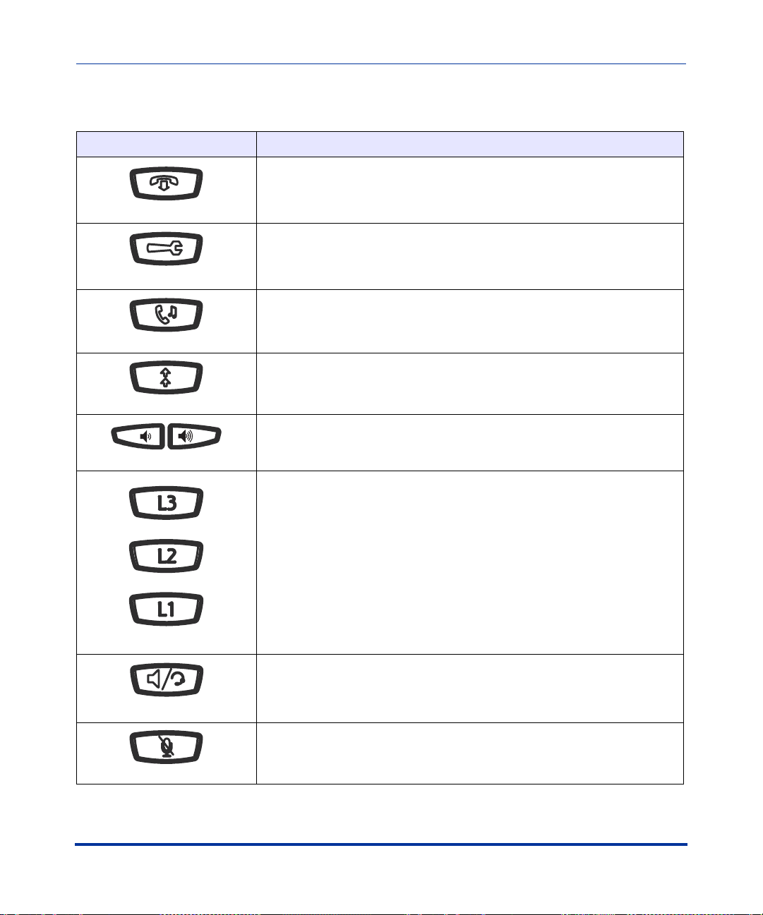
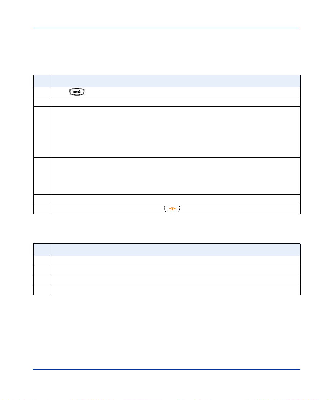
53i Key Descriptions*
Keys Key Description
Overview
Goodbye key - Ends an active call. The Goodbye key also exits an open
list, such as the Options List, without saving changes.
Options key - Accesses options to customize your phone. Your System
Administrator may have already customized some of your settings. Check
with your System Administrator before changing the administrator-only
options.
Hold key - Places an active call on hold. To retrieve a held call, press the
call appearance button beside the light that is flashing.
Redial key - Redials up to 100 previously dialed numbers. Pressing the
Redial key twice simultaneously redials the last dialed number.
Volume control key - Adjusts the volume for the handset, headset, ringer,
and handsfree speaker.
Line/Call Appearance key - Connects you to a line or call. The Aastra 53i
IP phone supports up to 3 line keys.
Handsfree key - Activates Handsfree for making and receiving calls
without lifting the handset. When the audio mode option is set, this key is
used to switch between a headset and the handsfree speakerphone.
Mute key - Mutes the microphone so that your caller cannot hear you (the
light indicator flashes when the microphone is on mute).
1-6 41-001160-00, Release 2.1, Rev 04
Page 25
Overview
IP Phone Models
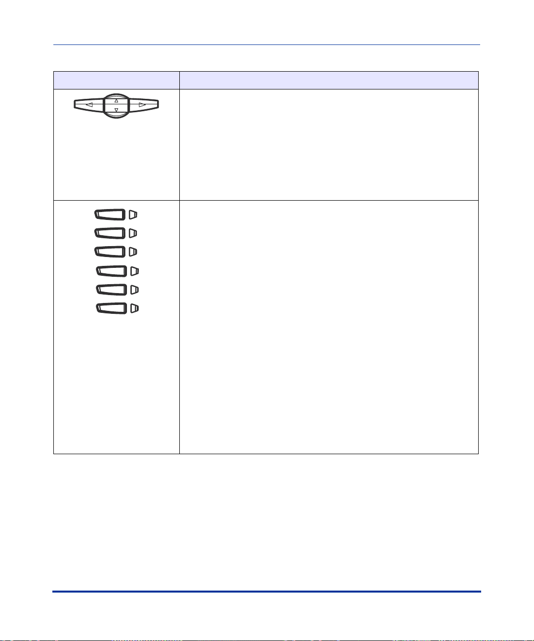
Keys Key Description
Navigation keys - Pressing the UP and DOWN arrow keys lets you view
different status and text messages on the LCD display (if there is more
than 1 line of status/text messages). These buttons also let you scroll
through menu selections, such as the Options List.
Pressing the LEFT and RIGHT arrow keys lets you view the different line/
call appearances. While in the Options List, these keys allow you to exit or
enter the current option. When you are editing entries on the display,
pressing the LEFT arrow key erases the character on the left; pressing the
RIGHT arrow key sets the option.
Programmable keys - 6 Top Keys: 4 keys are programmable.
Keys 1 and 2 are hardcoded as the SAVE and DELETE keys, respectively,
and cannot be altered.
The following are the default functions for the programmable keys on the
53i IP phone:
1 - SAVE Allows you to save numbers and/or names to the
(hardcoded) Directory. Using this key, you enter the number,
2 - DELETE Allows you to delete a single entry or all entries from
(hardcoded) the Directory List and Callers List.
3 - DIRECTORY Displays up to 200 names and phone numbers
4 - CALLERS LIST Accesses the last 200 calls received.
5 - TRANSFER Transfers the active call to another number.
6 - CONFERENCE Begins a conference call with the active call.
Overview
name, and line (or speeddial key) to record in the
Directory List.
(stored in alphabetical order).
Note: For more information about programming keys 3, 4, 5, and 6 to
perform specific functions, see Chapter 5, “Configuring Operational
Features” the section, “Softkeys/Programmable Keys/Feature Keys/
Expansion Module Keys” on page 5-93.
*See the Aastra 53i User Guide for more information about each of these keys.
41-001160-00, Release 2.1, Rev 04 1-7
Page 26
IP Phone Administrator Guide
IP Phone Models
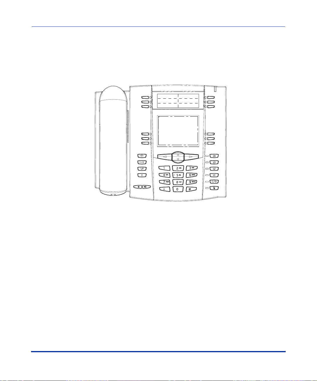
Model 55i IP Phone
This section provides brief information about the Model 55i IP Phone. It includes
a list of features, and describes the hard keys, default programmable keys, and
default softkeys on the 55i.
Overview
55i Phone Features
• 8 line graphical LCD screen (144 x 75 pixels) with white backlight
• 12 programmable keys
• 6 Top keys:Programmable hard keys
(up to 6 programmable functions)
• 6 Bottom keys:Programmable state-based softkeys
(up to 20 programmable functions)
• 4 call appearance lines with LEDs
• Supports up to 9 call lines
• Full-duplex speakerphone for handsfree calls
• Headset support (modular connector)
• Built-in-two-port, 10/100 Ethernet switch - lets you share a connection with
your computer.
1-8 41-001160-00, Release 2.1, Rev 04
Page 27
Overview
IP Phone Models
Keys Key Description
• Inline power support (based on 802.3af standard) which eliminates power
adapters.
• AC power adapter (included)
• Enhanced busy lamp fields*
• Set paging*
*Availability of feature dependant on your phone system or service provider.
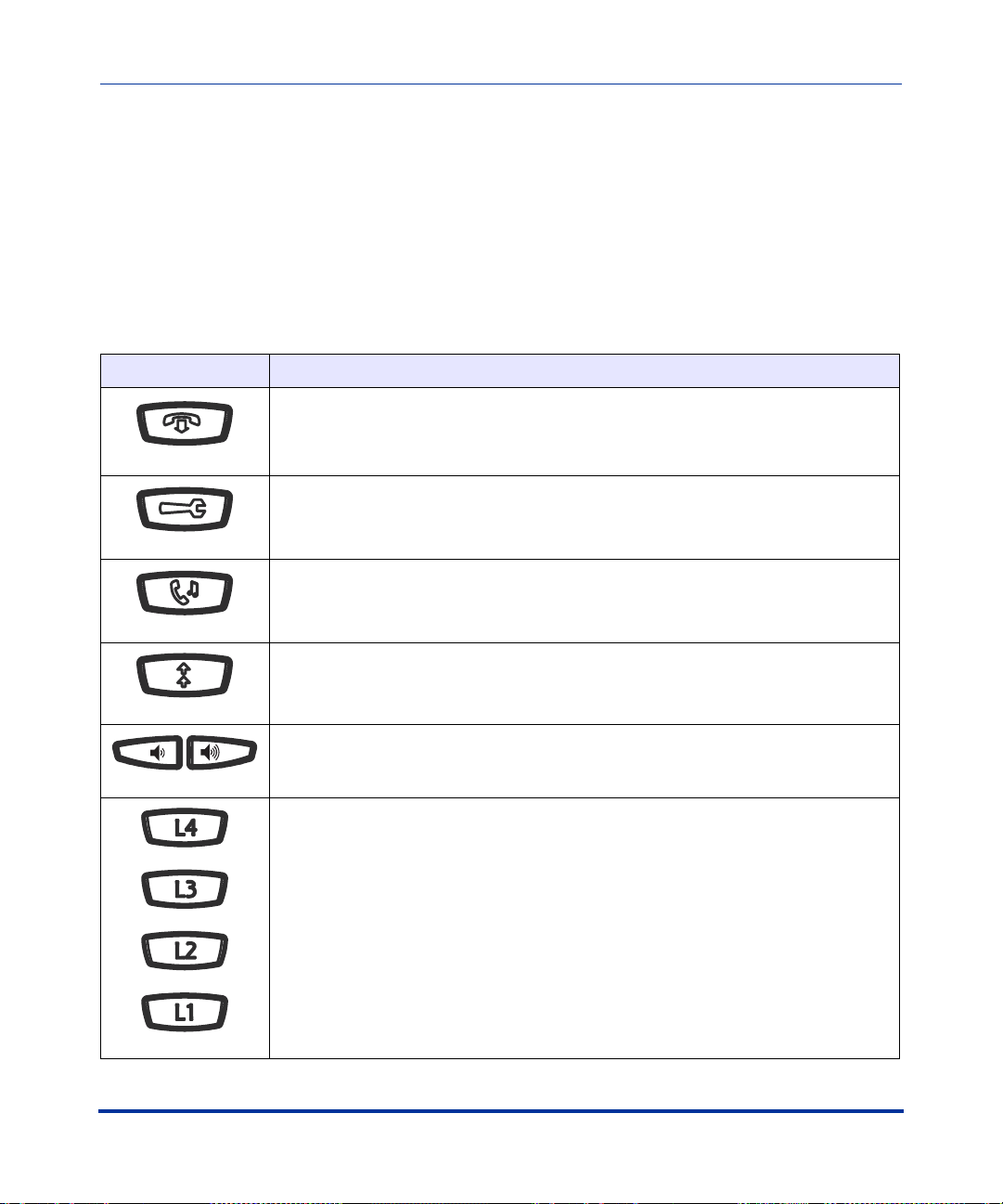
55i Key Descriptions*
Goodbye key - Ends an active call. The Goodbye key also exits an open list, such
as the Options List, without saving changes.
Options key - Accesses options to customize your phone. Your System
Administrator may have already customized some of your settings. Check with your
System Administrator before changing the administrator-only options.
Hold key - Places an active call on hold. To retrieve a held call, press the call
appearance button beside the light that is flashing.
Overview
Redial key - Redials up to 100 previously dialed numbers. Pressing the Redial key
twice simultaneously redials the last dialed number.
Volume control key - Adjusts the volume for the handset, headset, ringer, and
handsfree speaker.
Line/Call Appearance key - Connects you to a line or call. The Aastra 55i IP phone
supports up to 4 line keys.
41-001160-00, Release 2.1, Rev 04 1-9
Page 28
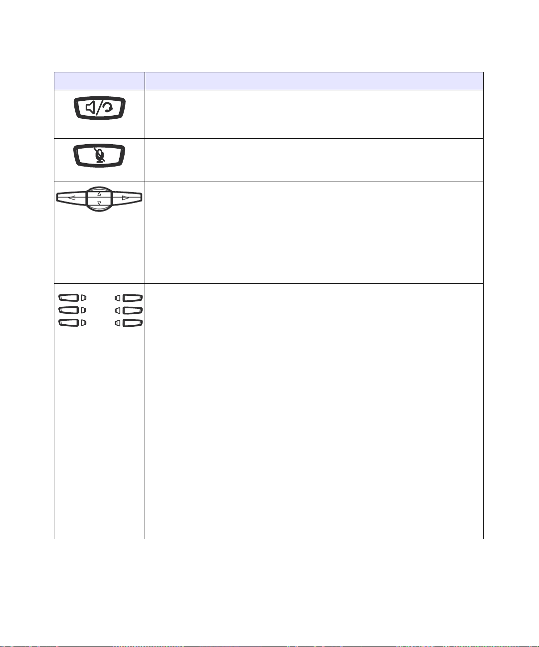
Keys Key Description
Handsfree key - Activates Handsfree for making and receiving calls without lifting
the handset. When the audio mode option is set, this key is used to switch between
a headset and the handsfree speakerphone.
Mute key - Mutes the microphone so that your caller cannot hear you (the light
indicator flashes when the microphone is on mute).
Navigation keys - Pressing the UP and DOWN arrow keys lets you view different
status and text messages on the LCD display (if there is more than 1 line of status/
text messages). These buttons also let you scroll through menu selections, such as
the Options List.
Pressing the LEFT and RIGHT arrow keys lets you view the different line/call
appearances. While in the Options List, these keys allow you to exit or enter the
current option. When you are editing entries on the display, pressing the LEFT arrow
key erases the character on the left; pressing the RIGHT arrow key sets the option.
Programmable keys - 6 Top keys: programmable hard keys (up to 6 programmable
functions)
By default, the top keys 1 through 4 are assigned as Services, Directory, Callers List,
and Intercom, respectively. Keys 5 and 6 have no assigned functions. All 6 keys are
programmable and can be assigned to perform specific functions.
The following are the default functions for the programmable keys on the 55i IP
phone:
1 - SERVICES Accesses enhanced features and services such as XML
applications and voicemail, provided by third parties.
2 - DIRECTORY Displays up to 200 names and phone numbers (stored in
alphabetical order).
3 - CALLERS LIST Accesses the last 200 calls received.
4 - ICOM Accesses another extension on the network.
5 - NONE No assigned function.
6 - NONE No assigned function.
Note: For more information about configuring the programmable keys 1 through 6 to
perform specific functions, see Chapter 5, “Configuring Operational Features” the
section, “Softkeys/Programmable Keys/Feature Keys/Expansion Module Keys” on
page 5-93.
Page 29
Overview
IP Phone Models
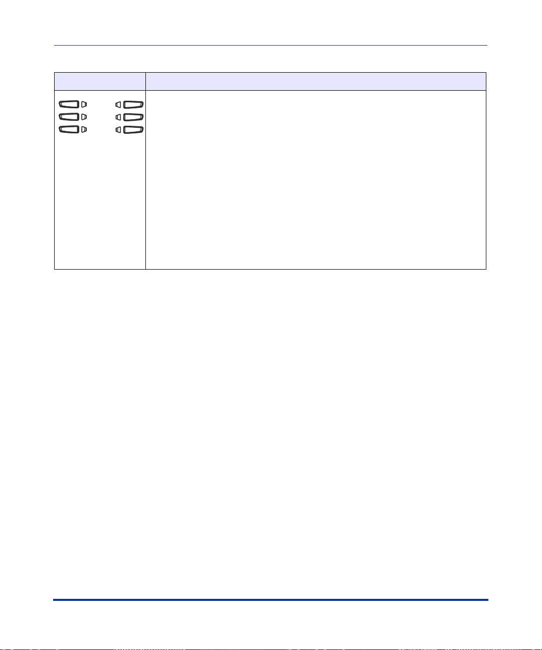
Keys Key Description
Softkeys - 6 Bottom keys: programmable state-based softkeys (up to 20
programmable functions).
By default, keys 1 through 6 have no assigned functions. You can configure all 6
bottom softkeys to perform specific functions on the 55i IP phone. However, after
you lift the handset, there are specific static softkeys that display that cannot be
changed. These are as follows:
1 - DIAL Allows you to dial out on the phone.
2 - CONF Begins a conference call with the active phone.
3 - XFER Transfers the active call to another number.
Note: For more information about configuring softkeys 1 through 6 to perform
specific functions, see Chapter 5, “Configuring Operational Features” the section,
“Softkeys/Programmable Keys/Feature Keys/Expansion Module Keys” on
page 5-93.
*See the Aastra 55i User Guide for more information about each of these keys.
Overview
41-001160-00, Release 2.1, Rev 04 1-11
Page 30

IP Phone Administrator Guide
IP Phone Models
Model 57i and 57i CT IP Phone
This section provides brief information about the Model 57i IP Phone. It includes
a list of features, and describes the hard keys and default softkeys on the 57i.
Overview
57i and 57i CT Phone Features
• 11 line graphical LCD screen (144 x 128 pixels) with white backlight
• 12 multi-functional softkeys
- 6 Top Keys: programmable static softkeys (up to 10 programmable
functions)
- 6 Bottom Keys: programmable state-based softkeys (up to 20 programmable
functions)
• 4 call appearance lines with LEDs
• Supports up to 9 call lines
• Full-duplex speakerphone for handsfree calls
• Headset support (modular connector)
• Built-in-two-port, 10/100 Ethernet switch - lets you share a connection with
your computer.
1-12 41-001160-00, Release 2.1, Rev 04
Page 31

Overview
IP Phone Models
Keys Key Description
• Inline power support (based on 802.3af standard) which eliminates power
adapters.
• AC power adapter (included)
• Enhanced busy lamp fields*
• Set paging*
*Availability of feature dependant on your phone system or service provider.
57i and 57i CT Key Descriptions*
Goodbye key - Ends an active call. The Goodbye key also exits an open list, such
as the Options List, without saving changes.
Options key - Accesses options to customize your phone. Your System
Administrator may have already customized some of your settings. Check with your
System Administrator before changing the administrator-only options.
Hold key - Places an active call on hold. To retrieve a held call, press the call
appearance button beside the light that is flashing.
Overview
Redial key - Redials up to 100 previously dialed numbers. Pressing the Redial key
twice simultaneously redials the last dialed number.
Volume control key - Adjusts the volume for the handset, headset, ringer, and
handsfree speaker.
Line/Call Appearance key - Connects you to a line or call. The Aastra 57i IP phone
supports up to 4 line keys.
41-001160-00, Release 2.1, Rev 04 1-13
Page 32

IP Phone Administrator Guide
IP Phone Models
Keys Key Description
Handsfree key - Activates Handsfree for making and receiving calls without lifting
the handset. When the audio mode option is set, this key is used to switch between
a headset and the handsfree speakerphone.
Mute key - Mutes the microphone so that your caller cannot hear you (the light
indicator flashes when the microphone is on mute).
Overview
Navigation keys - Pressing the UP and DOWN arrow keys lets you view different
status and text messages on the LCD display (if there is more than 1 line of status/
text messages). These buttons also let you scroll through menu selections, such as
the Options List.
Pressing the LEFT and RIGHT arrow keys lets you view the different line/call
appearances. While in the Options List, these keys allow you to exit or enter the
current option. When you are editing entries on the display, pressing the LEFT arrow
key erases the character on the left; pressing the RIGHT arrow key sets the option.
1-14 41-001160-00, Release 2.1, Rev 04
Page 33

Overview
IP Phone Models
Keys Key Description
Softkeys - 12 softkeys on the 57i IP Phone.
- 6 Top Keys: programmable static softkeys (up to 10 programmable functions)
- 6 Bottom Keys: programmable state-based softkeys (up to 20 programmable
functions)
By default, the top softkeys 1 through 4 are assigned as Services, Directory, Callers
List, and Intercom, respectively. Keys 5 and 6 have no assigned functions. All 6 keys
are programmable and can be assigned to perform specific functions.
The following are the default functions for the top softkeys on the 57i IP phone:
1 - SERVICES Accesses enhanced features and services such as XML
2 - DIRECTORY Displays up to 200 names and phone numbers (stored in
3 - CALLERS LIST Accesses the last 200 calls received.
4 - ICOM Accesses another extension on the network.
5 - NONE No assigned function.
6 - NONE No assigned function.
By default, the bottom softkeys 7 through 12 have no assigned functions. You can
configure all 6 bottom softkeys to perform specific functions on the 57i IP phone.
However, after you lift the handset, there are specific static softkeys that display that
cannot be changed. These are as follows:
Overview
applications and voicemail, provided by third parties.
alphabetical order).
7- DIAL Allows you to dial out on the phone.
8- CONF Begins a conference call with the active phone.
9- XFER Transfers the active call to another number.
Note: For more information about programming the softkeys to perform specific
functions, see Chapter 5, “Configuring Operational Features” the section, “Softkeys/
Programmable Keys/Feature Keys/Expansion Module Keys” on page 5-93.
*See the Aastra 57i or 57i CT User Guide for more information about each of these keys.
41-001160-00, Release 2.1, Rev 04 1-15
Page 34

IP Phone Administrator Guide
IP Phone Models
57i CT Cordless Handset Features
• 5 line backlit display screen
• 2 multi-functional softkeys
• Programmable function key supports up to 14 functions
• Vibration Alerter
• Headset Jack
• Desk charging stand
Overview
57i CT Cordless Handset Key Descriptions
Function # Function Description
1 Receiver
2 Volume key
During Ringing: Adjusts ringer volume
During a call: Adjusts receiver volume
During text mode (not in a call): Moves cursor right/left
3 Display
4 Features ƒ Key List
Access key to the programmed Feature Key List
Scrolls up when in the various lists
Adds a space during editing
1-16 41-001160-00, Release 2.1, Rev 04
Page 35

Overview
IP Phone Models
Function # Function Description
5 Softkeys
Activates feature or option shown on the display above
the keys
6 Call key
Used to obtain dial tone
Also used as a Hold key
7 Dial Pad
8 Mute Key
When used, prevents the caller from hearing you
9 Headset Jack
10 Status Light
11 Release key
To end calls and go on hook
Exits Menu and the various lists
12 Menu Key
Access key to the different Options
Scrolls down when in the various lists
Used as Backspace during editing
13 Redial Key
Displays the last 10 numbers dialed
14 Charging Jack
15 Charging Contacts
16 Microphone
Overview
41-001160-00, Release 2.1, Rev 04 1-17
Page 36

IP Phone Administrator Guide
Firmware Installation Information
Firmware Installation Information
Description
The firmware setup and installation for the IP phone can be done using any of the
following:
Overview
• Phone keypad menu (Phone UI)
• Aastra Web-based user interface (Aastra Web UI)
When the IP phone is initialized for the first time, DHCP is enabled by default.
Depending on the type of configuration server setup you may have, the IP phone
may download a firmware version automatically, or you may need to download it
manually.
Installation Considerations
The following considerations must be made before connecting the IP phone to the
network:
• If you are planning on using dynamic IP addresses, make sure a DHCP server
is enabled and running on your network.
• If you are not planning on using dynamic IP addresses, see Chapter 4, the
section, “Configuring Network Settings Manually” on page 4-8 for manually
setting up an IP address.
To install the IP phone hardware and cabling, refer to the model-specific
SIP IP Phone Installation Guide.
1-18 41-001160-00, Release 2.1, Rev 04
Page 37

Overview
Firmware Installation Information
Installation Requirements
The following are general requirements for setting up and using your SIP IP
phone:
• SIP-based IP PBX system or network installed and running with a SIP
account created for the 53i IP phone.
• Access to a Trivial File Transfer Protocol (TFTP), File Transfer Protocol
(FTP), Hypertext Transfer Protocol (HTTP) server, or HyperText Transfer
Protocol over Secure Sockets Layer (SSL) (HTTPS).
• Ethernet/Fast Ethernet LAN (10/100 Mb)
• Category 5/5e straight through cabling
•Power source
— For Ethernet networks that supply in-line power to the phone (IEEE
802.3af):
— For power, use the Ethernet cable (supplied) to connect from the
phone directly to the network for power. (No 48v AC power adapter
required.)
— For Ethernet networks that DO NOT supply power to the phone:
— For power, use the 48V AC Power Adapter (included) to connect
from the DC power port on the phone to a power source.
or
Overview
— (optional) - For power, use a Power over Ethernet (PoE) power
injector or a PoE switch. A PoE power injector is available as an
optional accessory from Aastra Telecom. Contact your Administrator
for more information.
41-001160-00, Release 2.1, Rev 04 1-19
Page 38

IP Phone Administrator Guide
Firmware Installation Information
Configuration Server Requirement
A basic requirement for setting up the IP phone is to have a configuration server.
The configuration server allows you to:
• Store the firmware images that you need to download to your IP phone.
• Stores configuration files for the IP phone
• Stores the software when performing software upgrades to the IP phone
Overview
Reference
To set the protocol for your configuration server, see Chapter 4, the section,
“Configuring the Configuration Server Protocol” on page 4-79.
For setting up your configuration server, see Appendix B, “Configuration Server
Setup.”
Note: If you use TFTP, the configuration server must be able to accept
connections anonymously.
1-20 41-001160-00, Release 2.1, Rev 04
Page 39

Overview
Firmware and Configuration Files
Firmware and Configuration Files
Description
When the IP phone is initialized for the first time, DHCP is enabled by default.
Depending on the type of configuration server setup you may have, the IP phone
may download a firmware version and configuration files automatically, or you
may need to download it manually.
Note: Automatic download is dependant on your configuration server
setup.
The firmware consists of a single file called:
• <phone model>.st
The configuration files consist of two files called:
• aastra.cfg
•<mac>.cfg
The following table provides the firmware for each Aastra IP phone model.
Overview
IP Phone
Model
53i 53i.st
55i 55i.st
57i 57i.st
57i CT 57i Cordless.st
The IP Phone firmware file includes all the necessary files you need for your
phone, including the language files. Loading the language files to your phone(s) is
optional. For more information about loading languages files, see Chapter 5, the
section, “Customizing the Display Columns on the 560M Expansion Module” on
page 5-224.
41-001160-00, Release 2.1, Rev 04 1-21
Associated
Firmware
Page 40

IP Phone Administrator Guide
Firmware and Configuration Files
Configuration File Precedence
Aastra IP phones can accept two sources of configuration data:
• The server configuration most recently downloaded/cached from the
configuration server files, aastra.cfg/<mac>.cfg (or the aastra.tuz/<mac>.tuz
encrypted equivalents).
• Local configuration changes stored on the phone that were entered using
either the IP phone UI or the Aastra Web UI
Overview
In the event of conflicting values set by the different methods, values are applied
in the following sequence:
1. Default values hard-coded in the phone software
2. Values downloaded from the configuration server
3. Values stored locally on the phone
The last values to be applied to the phone configuration are the values that take
effect.
For example, if a parameter’s value is set in the local configuration (via Aastra
Web UI or IP phone UI) and the same value was also set differently in one of the
<mac>.cfg/aastra.cfg files on the configuration server, the local configuration
value is the value that takes effect because that is the last value applied to the
configuration.
1-22 41-001160-00, Release 2.1, Rev 04
Page 41

Overview
Firmware and Configuration Files
Installing the Firmware/Configuration Files
The following procedure describes how to install the firmware and configuration
files.
Step Action
1 If DHCP is disabled, manually enter the configuration server’s IP address. For details on manually
setting DHCP, see Chapter 4, the section “DHCP” on page 4-4.
2 Copy the firmware file <phone model>.st to the root directory of the configuration server. The IP
phone accepts the new firmware file only if it is different from the firmware currently loaded on the IP
phone.
Note: The <phone model> attribute is the IP phone model (i.e., 53i.st, 55i.st)
3 Copy the Aastra configuration files (aastra.cfg and <mac>.cfg) to the root directory of the
configuration server.
Note: The <mac> attribute represents the actual MAC address of your phone.
(i.e., 00085D030996.cfg).
4 Note: Restart the IP phone as described in Chapter 3, “Restarting Your Phone” on page 3-13.
Overview
41-001160-00, Release 2.1, Rev 04 1-23
Page 42

Page 43

Configuration Interface Methods
About this chapter
Introduction
This chapter describes the methods you, as an Administrator, can use to configure
the IP phones.
Note: Features, characteristics, requirements, and configuration that are
specific to a particular IP phone models are indicated where required in
this guide.
Chapter 2
Configuration Interface Methods
Topics
This chapter covers the following topics:
Topi c Page
Configuration Methods page 2-2
IP Phone UI page 2-2
Aastra Web UI page 2-5
Configuration Files (Administrator Only) page 2-15
41-001160-00, Release 2.1, Rev 04 2-1
Page 44

IP Phone Administrator Guide
Configuration Methods
Configuration Methods
Description
You can use the following to setup and configure the IP phone:
• IP phone UI
•Aastra Web UI
• Configuration files
Note: There are specific parameters you can configure using only the IP
Phone UI, only and Aastra Web UI, only the configuration files, or a
combination of any of these methods. For more information about
configuring the phone, see Chapter 4, Chapter 5, and Chapter 6.
The following paragraphs describe each method of configuring the IP Phone.
IP Phone UI
The IP Phone User Interface (UI) provides an easy way to access features and
functions for using and configuring the IP phone. An Administrator can configure
all features and functions on the phone. A User can configure a subset of these
features and functions. Users of the IP phones should see their Model-specific
User’s Guide for available features and functions to configure.
You use the phone’s hard keys and keypad to configure specific features on the IP
phone. By default, specific softkeys/programmable keys on each phone model can
also access the Directory List and Callers List, and initiate transfers and
Configuration Interface Methods
2-2 41-001160-00, Release 2.1, Rev 04
conference calls.
Reference
Refer to Chapter 1, the section “IP Phone Models” on page 1-2 for keys specific to
your phone model.
For more information about using the hard keys on each phone, see Chapter 5, the
section, “Locking IP Phone Keys” on page 5-28.
For more information about the softkeys/programmable keys, see Chapter 5, the
section, “Softkeys/Programmable Keys/Feature Keys/Expansion Module Keys”
on page 5-93.
Page 45

Configuration Interface Methods
Configuration Methods
Options Key
The Options key allows you to access the "Options List" on the IP phone.
Accessible options in this list are for both user and Administrator use. An
Administrator must enter a password for administrator options.
Note: An Administrator can apply a simplified options menu to the IP
phones. An Administrator can also enable and disable the use of an
Administrator password protection in the IP phone UI. These features are
configurable using the configuration files only.
For more information about these features, see Chapter 3, the section,
“Simplified IP Phone UI Options Menu” on page page 3-5, and Chapter
5, the section, “Administrator Passwords” on page 5-8.
This document describes the administrator options only. For a description of the
user options in the "Options List", see your model-specific SIP IP Phone User
Guide.
The following illustration indicates the location of the Options Key on each phone
model.
Configuration Interface Methods
Options Key
53i
55i
Options Key
57i/57i CT
41-001160-00, Release 2.1, Rev 04 2-3
57i CT Handset
Page 46
IP Phone Administrator Guide
Configuration Methods
Using the Options Key
From the 53i, 55i, or 57i/57i CT:
Step Action
1 Press on the phone to enter the Options List.
2Use the r and s to scroll through the list of options.
3 On 53i:
To select an option, press the Enter softkey, or select the number on the keypad that corresponds to
the option in the Option List.
On the 55i, 57i, 57i CT:
To select an option, press the Select softkey, press
corresponds to the option in the Option List.
4 On 53i:
Use the Set softkey after making a change to an option, to save the change.
On the 55i, 57i, 57i CT:
Use the Change softkey to change a selected option.
5 Press the Done softkey at any time to save the changes and exit the current option.
6 Press the Cancel softkey, press
3, or press at any time to exit without saving changes.
4, or select the number on the keypad that
From the 57i CT handset:
Step Action
1 Press the
2 Use the scroll keys
3 To select and change an option, press the
Configuration Interface Methods
4 Press
2-4 41-001160-00, Release 2.1, Rev 04
 key to enter the Options List when the phone is not in use.
 and Ï to scroll the options.
r keys.
y when done.
Page 47

Configuration Interface Methods
Configuration Methods
Aastra Web UI
An administrator can setup and configure the IP phone using the Aastra Web UI.
The Aastra Web UI supports Internet Explorer and Gecko engine-based browsers
like Firefox, Mozilla or Netscape.
HTTP/HTTPS Support
The Aastra Web UI supports both Hypertext Transfer Protocol (HTTP) and
Hypertext Transfer Protocol over Secure Socket Layer (HTTPS) client and server
protocols.
HTTP is the set of rules for transferring files (text, graphic images, sound,
video, and other multimedia files) over the Internet. When you open your
Web browser, you are indirectly making use of HTTP. HTTP is an
application protocol that runs on top of the TCP/IP suite of protocols (the
foundation protocols for the Internet).
HTTPS is a Web protocol that encrypts and decrypts user page requests as well as
the pages that are returned by the Web server. HTTPS uses Secure Socket Layer
(SSL) or Transport Layer Security (TLS) as a sublayer under its regular HTTP
application layering.
security of a message transmission on the Internet. It uses a 40-bit key size
for the RC4 stream encryption algorithm, which is considered an adequate degree
of encryption for commercial exchange. TLS is a protocol that ensures privacy
between communicating applications and their users on the Internet. When a
server and client communicate, TLS ensures that no third party may eavesdrop or
tamper with any message. TLS is the successor to SSL.
Configuration Interface Methods
SSL is a commonly-used protocol for managing the
Note: HTTPS uses port 443 instead of HTTP port 80 in its interactions
with the TCP/IP lower layer.
41-001160-00, Release 2.1, Rev 04 2-5
Page 48

IP Phone Administrator Guide
Configuration Methods
HTTP/HTTPS Client and Server Support
The Aastra IP phones allow for HTTP request processing and associated data
transfers to perform over a secure connection (HTTPS). The IP phones support
the following:
• Transfer of firmware images, configuration files, script files, and web page
content over a secure connection.
• Web browser phone configuration over a secure connection.
• TLS 1.0or SSL 3.0 methods for both client and server
HTTPS Client
When an HTTPS client opens and closes its TCP socket, the SSL software
respectively handshakes upon opening and disconnects upon closing from the
HTTPS server. The main HTTPS client functions are:
• Downloading of configuration files and firmware images.
• Downloading of script files based on an “HTTPS://” URL supplied by a
softkey definition.
HTTPS Server
The HTTPS server provides HTTP functionality over secure connections. It
coexists with the HTTP server but has its own set of tasks. The main HTTPS
server functions are:
• Delivery of web page content to a browser client over a secure connection.
• Execution of HTTP GET and POST requests received over a secure
Configuration Interface Methods
2-6 41-001160-00, Release 2.1, Rev 04
connection.
Page 49

Configuration Interface Methods
Configuration Methods
Using HTTPS via the Aastra Web UI
HTTPS is enabled by default on the IP phones. When you open a browser window
and enter an IP address or host name for a phone using HTTP, a server redirection
occurs which automatically converts an HTTP connection to an HTTPS
connection. After the redirection, a “Security Alert” certificate window displays
alerting the user that information exchanged with the phone cannot be viewed or
changed by others. Accepting the certificate then forwards you to the phone’s Web
UI.
Notes:
1. The private key and certificate generate outside the phone and embed
in the phone firmware for use by the HTTPS server during the SSL
handshake.
2. Using the configuration files, the IP phone UI, or the Aastra Web UI,
you can configure the following regarding HTTPS:
Configuration Interface Methods
- Specify HTTPS security client method to use (TLS 1.0 or SSL 3.0)
- Enable or disable HTTP to HTTPS server redirect function
- HTTPS server blocking of XML HTTP POSTS to the phone
Reference
For more information on configuring the HTTPS protocol, see Chapter 4,
“Configuring Network and Session Initiation Protocol (SIP) Features”, the
sections:
• “Configuring the Configuration Server Protocol” on page 4-79
• “HTTPS Client/Server Configuration” on page 4-23
41-001160-00, Release 2.1, Rev 04 2-7
Page 50

IP Phone Administrator Guide
Configuration Methods
Accessing the Aastra Web UI
Use the following procedure to access the Aastra Web UI.
Step Action
1 Open your web browser and enter the phone’s IP address or host name into the address field.
The following Login screen displays.
IP address or
host name
Configuration Interface Methods
2-8 41-001160-00, Release 2.1, Rev 04
Page 51

Configuration Interface Methods
Configuration Methods
Step Action
2 Enter your username and password and click .
Note: For an administrator, the default username is “admin” and the password is “22222”.
For a user, the default username is “user” and the password field is left blank.
The IP phones accept numeric passwords only.
The Network Status window displays for the IP phone you are accessing. The following illustration is
an example of a Network Status screen for the 55i IP phone
55i Network
Status Window
Logout button
.
Configuration Interface Methods
3 You can logout of the Aastra Web UI at any time by clicking LOGOFF.
41-001160-00, Release 2.1, Rev 04 2-9
Page 52

The following categories display in the side menu of the Aastra Web UI: Status,
Operation, Basic Settings, Advanced Settings.
Status
The Status section displays the network status and the MAC address of the IP
phone. It also displays hardware and firmware information about the IP phone.
The information in the Network Status window is read-only.
Operation
The Operation section provides the following options:
Heading Description
User Password Allows you to change user password.
(Applicable to User and Administrator).
Phone Lock Allows you to assign an emergency dial plan to the phone,
lock the phone to prevent any changes to the phone and to
prevent use of the phone, and reset the user password.
Note: You can also configure a softkey to use for locking/
unlocking the phone.
(Applicable to User and Administrator).
Programmable Keys 53i - 6 Top programmable keys (up to 4 programmable
functions)
55i - 6 Top programmable hard keys (up to 6 programmable
functions)
(Applicable to User and Administrator).
Softkeys and XML 55i - 6 Bottom programmable state-based softkeys (up to 20
programmable functions)
57i/57i CT - 6 Top programmable, static softkeys (up to 10
programmable functions; and 6 bottom programmable
state-based softkeys (up to 20 programmable functions)
(Applicable to User and Administrator).
Page 53

Configuration Interface Methods
Configuration Methods
Heading Description
Expansion Module <N> The 536M has up to 36 configurable keys. The 560M has up
to 60 configurable keys. You can have up to 3 expansion
modules attached to a single phone allowing you to
configure keys for Expansion Module 1, Expansion Module
2, and Expansion Module 3.See your Model-specific User
Guide for applicable expansion modules for your model
phone.
(Applicable to User and Administrator).
Handset Keys
(57i CT only)
Directory Allows you to copy the Callers List and Directory List from
Reset Allows you to restart the IP phone when required.
Allows you to configure up to 15 softkeys on the handset.
(Applicable to User and Administrator).
your IP phone to your PC.
(Applicable to User and Administrator).
(Applicable to User and Administrator).
This setting also allows you to set the IP phone back to its
factory default settings or remove the local configuration.
(Applicable Administrator only).
Configuration Interface Methods
41-001160-00, Release 2.1, Rev 04 2-11
Page 54

IP Phone Administrator Guide
Configuration Methods
Basic Settings
The Basic Settings section provides the following options:
Heading Description
Preferences Allows you to set the following General specifications on the
IP phone.
• Local Dial Plan (Admin Only)
• Send Dial Plan Terminator (Admin Only)
• Digit Timeout (Admin Only)
• Park Call (not available on 53i)
• Pickup Parked Call (not available on 53i)
• Suppress DTMF Playback
• Display DTMF Digits
• Call Waiting
• Play Call Waiting Tone
• Stuttered Dial Tone
• XML Beep Support
• Status Scroll Delay
• Incoming Call Interrupts Dialing
• Goodbye Key Cancels Incoming Call
• UPnP Mapping Lines
• Message Waiting Indicator Line
This section also allows you to set:
• Incoming Intercom Settings
• Outgoing Intercom Settings (Admin Only; Administrator
can enable these or a User if required)
• Key Mapping (Admin Only)
• Ring Tones
• Priority Alert Settings (Admin Only)
Configuration Interface Methods
Call Forward Allows you to set a phone number destination for where you
2-12 41-001160-00, Release 2.1, Rev 04
• Directed Call Pickup Settings (Admin Only)
• Auto Call Distribution Settings (Admin Only)
• Time and Date Settings
• Language Settings (Admin only can specify the
language pack names to load to the phone).
want calls forwarded.
Page 55

Configuration Interface Methods
Configuration Methods
Advanced Settings
The Advanced Settings section provides the following options:
Heading Description
Network Allows you to set Basic Network Settings, Advanced
Global SIP Allows you to set global Basic SIP Authentication Settings,
Lines 1 through 9 Allows you to set per-line Basic SIP Authentication Settings,
Configuration Interface Methods
Network Settings, Type of Service DSCP, and VLAN
settings.
(Applicable to Administrator Only)
Basic SIP Network Settings, Advanced SIP Settings,
Real-time Transport Protocol (RTP) settings, and Autodial
Settings that apply to all lines on the IP phone.
(Applicable to Administrator Only)
Basic SIP Network Settings, Advanced SIP Settings,
Real-time Transport Protocol (RTP) settings, and Autodial
Settings that apply to specific lines on the IP phone.
(Applicable to Administrator Only)
Action URI Allows an administrator to specify a uniform resource
identifier (URI) that triggers a GET when certain events
occur.
(Applicable to Administrator Only)
Configuration Server Allows you to set the protocol to use on the configuration
server (TFTP (default), FTP, HTTP, or HTTPS), configure
automatic firmware and configuration file updates, enable/
disable auto-resync, and assign an XML push server list.
(Applicable to Administrator Only)
Firmware Update Allows you to manually perform a firmware update on the IP
phone from the configuration server.
(Applicable to Administrator Only)
41-001160-00, Release 2.1, Rev 04 2-13
Page 56
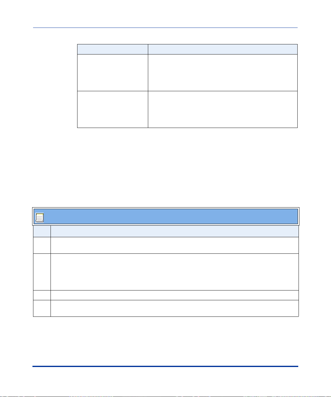
IP Phone Administrator Guide
Configuration Methods
Heading Description
TLS Support Allows you to specify the SIP Root and Intermediate
Troubleshooting Allows you to perform troubleshooting tasks whereby the
Enabling/Disabling the Aastra Web UI
The Aastra Web UI is enabled by default on the IP phones. A System
Administrator can disable the Aastra Web UI on a single phone or on all phones if
required using the configuration files. Use the following procedure to enable and
disable the Aastra Web UI.
Certificate files to use when the phone uses the TLS
transport protocol to setup a call.
(Applicable to Administrator Only)
results can be forwarded to Aastra Technical Support for
analyzing and troubleshooting.
(Applicable to Administrator Only)
To disable the Aastra Web UI:
Configuration Files
Step Action
1 Using a text-based editing application, open the <mac>.cfg file if you want to disable the Web UI on a
single phone. Open the aastra.cfg file to disable the Web UI on all phones
2 Enter the following parameter:
web interface enabled: 0
Configuration Interface Methods
Note: A value of zero (0) disables the Web UI on the phone. A value of 1 enables the Web UI.
3 Save the changes and close the <mac>.cfg or the aastra.cfg file.
4 Restart the phone to apply the changes. The Aastra Web UI is disabled for a single IP phone or for all
phones.
2-14 41-001160-00, Release 2.1, Rev 04
Page 57

Configuration Interface Methods
Configuration Methods
Configuration Files (Administrator Only)
A system administrator can enter specific parameters in the configuration files to
configure the IP phones. All parameters in configuration files can only be set by
an administrator.
You can enter specific configuration parameters in either of the following
configuration files:
• aastra.cfg
•<mac>.cfg
References
For information about configuration file precedence, see Chapter 1, “Overview.”
For a description of each configuration file parameter, see Appendix A,
“Configuration Parameters.”
Using the Configuration Files
When you use the configuration files to configure the IP phones, you must use a
text-based editing application to open the configuration file (aastra.cfg or
<mac>.cfg).
Configuration Interface Methods
Use the following procedure to add, delete, or change parameters and their
settings in the configuration files.
Note: Apply this procedure wherever this Administrator Guide refers to
configuring parameters using the configuration files.
41-001160-00, Release 2.1, Rev 04 2-15
Page 58

IP Phone Administrator Guide
Configuration Methods
Configuration files
Step Action
1 Using a text-based editing application, open the configuration file for the phone, for which you want to
configure the directory list (either aastra.cfg, <mac>.cfg or both).
2 Enter the required configuration parameters followed by the applicable value. For example,
directory 1: company_directory
directory 2: my_personal_directory
3 Save the changes and close the configuration file.
4 If the parameter requires the phone to be restarted in order for it to take affect, use the
IP Phone UI or the Aastra Web UI to restart the phone.
Configuration Interface Methods
2-16 41-001160-00, Release 2.1, Rev 04
Page 59

About this chapter
Introduction
The IP phones provide specific options on the IP Phone that only an Administrator
can access. These options are password protected and allow an Administrator to
change or set features and configuration information as required. For all models,
an Administrator can use the IP Phone UI, the Aastra Web UI, or the configuration
files to enter and change values.
Note: Specific options are configurable only via the IP Phone UI, and/or
Aastra Web UI, and/or configuration files.
Chapter 3
Administrator Options
Administrator Options
This chapter provides information about the available Administrator options.
Topics
This chapter covers the following topics:
Topi c Page
Administrator Level Options page 3-3
IP Phone UI Options page 3-3
Aastra Web UI Options page 3-7
Configuration File Options page 3-9
Phone Status page 3-10
Restarting Your Phone page 3-13
Set Phone to Factory Defaults/Erase Local Configuration page 3-15
Basic Settings page 3-19
41-001160-00, Release 2.1, Rev 04 3-1
Page 60

IP Phone Administrator Guide
About this chapter
Topi c Page
Network Settings page 3-31
Line Settings page 3-56
Softkeys, Programmable Keys, Expansion Module Keys page 3-57
Action URI page 3-58
Configuration Server Settings page 3-59
Firmware Update Features page 3-66
Administrator Options
3-2 41-001160-00, Release 2.1, Rev 04
Page 61

Administrator Options
Administrator Level Options
Administrator Level Options
Description
There are options on the IP phone that both a User and Administrator can access.
However, there are specific options that an Administrator can access only. These
options allow the Administrator to configure and manage local and/or remote IP
phones in a network.
An Administrator can access and manage these options using the IP Phone UI, the
Aastra Web UI, or the configuration files.
IP Phone UI Options
Using the IP Phone UI, you can access the Administrator options at
Options->Administrator Menu using the default password of "22222"
Options Menu
1. Call Forward
2. Preferences
3. Phone Status
4. User Password
5. Administrator Menu
6. Restart Phone
7. Phone Lock
8. Handset Pairing
Administrator Options
Administrator Menu
Handset Pairing
displays for CT
Models only.
Select
Done
Note: An administrator has the option of enabling and disabling the use
of password protection in the IP phone UI. This is configurable using the
configuration files only. For more information about this feature, see
Appendix A, the section “Password Settings” on page A-9.
41-001160-00, Release 2.1, Rev 04 3-3
Page 62

IP Phone Administrator Guide
Administrator Level Options
The following are administrator options in the "Options List" on the IP phone UI:
• Administrator Menu
— Configuration Server
— Network Settings
— SIP Settings
— Factory Default
— Erase Local Config.
References
For information about all other user options in the “Options Menu”, see your
model-specific SIP IP Phone User Guide.
For procedures on configuring Administrator Options on the IP phone via the IP
phone UI, see:
Chapter 4, “Configuring Network and Session Initiation Protocol (SIP) Features”
Chapter 5, “Configuring Operational Features”
Chapter 6, “Configuring Advanced Operational Features”
Administrator Options
3-4 41-001160-00, Release 2.1, Rev 04
Page 63
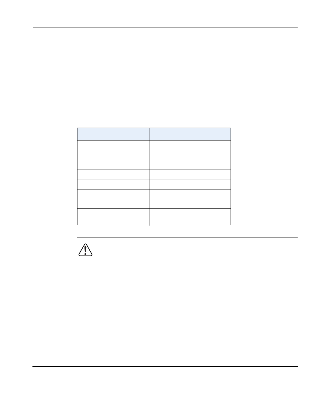
Administrator Options
Administrator Level Options
Simplified IP Phone UI Options Menu
An Administrator can replace the existing options menu on the Phone UI with a
more simplified options menu. In the configuration files, the “options simple
menu” parameter allows you to display either the full menu (if set to 0), or the
simplified menu (if set to 1). The following table illustrates the differences
between the full menu and the simplified menu.
When setting the “options simple menu” parameter, the menu changes in the
Phone UI only. The Aastra Web UI is not affected.
Full Options Menu Simplified Options Menu
Call Forward Call Forward
Preferences Preferences
Phone Status Phone Status
User Password Removed
Administrator Menu Removed
Restart Phone Removed
Phone Lock Phone Lock
Handset Pairing
(CT models only)
Administrator Options
Handset Pairing
(CT models only)
Warning: When using the simplified menu, you cannot change the
Network settings from the IP Phone UI. If the network settings become
misconfigured, you must “factory default” the phone and use the full
menu to recover the network settings from the Phone UI OR use the
Aastra Web UI to configure the network settings.
41-001160-00, Release 2.1, Rev 04 3-5
Page 64

IP Phone Administrator Guide
Administrator Level Options
Configuring the Simplified IP Phone UI Options Menu
You can enable the simplified IP Phone UI Options menu using the configurations
files only.
Configuration Files
For the specific parameter you can set in the configuration files, see Appendix A, the section, “Simplified IP
Phone UI Options Menu” on page A-5.
Administrator Options
3-6 41-001160-00, Release 2.1, Rev 04
Page 65

Administrator Options
Administrator Level Options
Aastra Web UI Options
An Administrator can configure specific options using the Aastra Web UI. These
options display after an Administrator logs into the Web UI using a Web browser
and entering the Admin username and password at the login prompt (The default
username is "admin" and the default password is "22222". The IP phones accept
numeric passwords only.) The column on the left side of the screen indicates the
configurable options. A User has limited configuration options as shown in the
following illustrations.
Administrator Web UI Menu
Administrator Options
User Web UI Menu
41-001160-00, Release 2.1, Rev 04 3-7
Page 66

IP Phone Administrator Guide
Administrator Level Options
The following are options that an Administrator can configure in the Aastra Web
UI (and are not available for the User to configure):
• Operation->Reset
— Restore to Factory Defaults
— Remove Local Configuration Settings
• Basic Settings->Preferences->General
— Local Dial Plan
— Send Dial Plan Terminator
— Digit Timeout (seconds)
• Basic Settings->Preferences->Outgoing Intercom Settings (User can
configure this via the Aastra Web UI if enabled by an Administrator)
• Basic Settings->Preferences->Key Mapping
• Basic Settings->Preferences->Priority Alerting Settings
• Basic Settings->Preferences->Directed Call Pickup Settings
• Basic Settings->Preferences->Auto Call Distribution Settings
• Basic Settings->Preferences->Language Settings
Administrator Options
3-8 41-001160-00, Release 2.1, Rev 04
— Language 1 (entering language pack filename)
— Language 2 (entering language pack filename)
— Language 3 (entering language pack filename)
— Language 4 (entering language pack filename)
• Advanced Settings
—Network
— Global SIP
— Line 1 through 9 Settings
— Action URI
— Configuration Server
— Firmware Update
— TLS Support
— Troubleshooting
Page 67

Administrator Options
Administrator Level Options
References
For information about options available to a User AND Administrator in the
Aastra Web UI, see your Model-specific User Guide.
For procedures to Restart your phone or restore factory defaults, see “Restarting
Your Phone” on page 3-13, and “Set Phone to Factory Defaults/Erase Local
Configuration” on page 3-15.
For more information about Advanced Settings for the IP Phone, see Chapter 4,
“Configuring Network and Session Initiation Protocol (SIP) Features.”
For procedures on configuring the Basic Settings for the IP Phone, see Chapter 5,
“Configuring Operational Features.”
Configuration File Options
An Administrator can enter specific parameters in the configuration files to
configure the IP phones. All parameters in configuration files can only be set by
an administrator.
Administrator Options
References
For a procedure on using the configuration files, see Chapter 2, the section,
“Configuration Files (Administrator Only)” on page 2-1.
For a description of each parameter you can enter in the configuration files, see
Appendix A, “Configuration Parameters.”
41-001160-00, Release 2.1, Rev 04 3-9
Page 68

IP Phone Administrator Guide
Administrator Level Options
Phone Status
The Phone Status on the IP Phone displays the network status and firmware
version of the IP phone.
You can display phone status using the IP phone UI or the Aastra Web UI.
Phone Status via IP Phone UI
In the IP phone UI, the Phone Status options are available to the user and the
administrator and do not require a password entry.
The following options display for phone status on the IP phone UI:
Phone Status Screen for 53i Phone
Phone Status
1. IP&MAC Addresses
2. LAN Port
3. PC Port
4. Firmware Info
Administrator Options
Phone Status Screen for 55i, 57i, and 57i CT Phones
=Next
=Enter
Phone Status
1. IP&MAC Addresses
2. LAN Port
3. PC Port
4. Firmware Info
Select
Done
3-10 41-001160-00, Release 2.1, Rev 04
Page 69
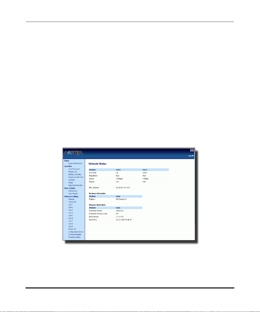
Administrator Options
Administrator Level Options
• IP&MAC Addresses
Displays the IP address and MAC address of the phone.
• LAN Port
Displays the Link State, Negotiation Method, Speed, and Duplex Method that
the phone uses on its LAN port.
• PC Port
Displays the Link State, Negotiation Method, Speed, and Duplex Method that
the phone uses on its PC Port.
• Firmware Info
Displays information about the firmware that is currently installed on the IP
phone.
Phone Status via Aastra Web UI
In the Aastra Web UI, the "Network Attributes", "Hardware Information", and
"Firmware Information" options display on the Network Status screen.
Administrator Options
41-001160-00, Release 2.1, Rev 04 3-11
Page 70

IP Phone Administrator Guide
Administrator Level Options
The following information displays for phone status in the Aastra Web UI at the
location Status->System Information. This information is available to the user
and the administrator as read-only.
• Network Attributes
Displays the network status of the Ethernet ports at the back of the phone. You
can also view the phone’s IP and MAC addresses. Information in this field
includes Link State, Negotiation, Speed, and Duplex for Port 0 and Port 1.
• Hardware Information
Displays the current IP phone platform and the revision number.
• Firmware Information
Displays information about the firmware that is currently installed on the IP
phone. Information in this field includes Firmware Version, Firmware Release
Code, Boot Version, Release Date/Time.
Administrator Options
3-12 41-001160-00, Release 2.1, Rev 04
Page 71

Administrator Options
Administrator Level Options
Restarting Your Phone
As System Administrator, there may be times when you need to restart a phone.
The Restart option allows you reboot the phone when required. A reset may be
necessary when:
• There is a change in your network, OR
• To re-load modified configuration files, OR
• If the settings for the IP phone on the IP PBX system have been modified.
You can restart the phone using the IP Phone UI or the Aastra Web UI.
Restarting the Phone Using the IP Phone UI
IP Phone UI
Step Action
1 Press on the phone to enter the Options List.
2Select Restart Phone.
3 For 53i:
Press # to confirm.
Administrator Options
Note: To cancel the Restart, press the 3 key.
For 55i, 57i, 57i CT:
Press Restart.
Note: To cancel the Restart, press Cancel.
41-001160-00, Release 2.1, Rev 04 3-13
Page 72

IP Phone Administrator Guide
Administrator Level Options
Restarting the Phone Using the Aastra Web UI
Aastra Web UI
1 Click on Operation->Reset->Phone.
2 Click to restart the phone.
Administrator Options
3-14 41-001160-00, Release 2.1, Rev 04
Page 73

Administrator Options
Administrator Level Options
Set Phone to Factory Defaults/Erase Local Configuration
You can set phones to their factory default setting or remove a local phone’s
configuration using the IP Phone UI or the Aastra Web UI.
Setting Factory Defaults on the Phone
Factory default settings are the settings that reside on the phone after it has left the
factory. The factory default settings on the phone sets the factory defaults for all
of the settings in the aastra.cfg, <mac>.cfg, and local configuration. Performing
this action results in losing all user-modified settings.You can reset a phone to
factory defaults using the IP Phone UI or the Aastra Web UI.
Setting Factory Defaults Using the IP Phone UI
IP Phone UI
Step Action
1 Press on the phone to enter the Options List.
2Select Administrator Menu and enter your Administrator Password (default is 22222).
3Select Factory Default.
4 For 53i:
The “Restore Defaults?” prompt displays.
Press # to confirm.
Administrator Options
For 55i/57i/57i CT:
The “Reset phone to factory defaults?” prompt displays.
Press Default to confirm.
41-001160-00, Release 2.1, Rev 04 3-15
Page 74
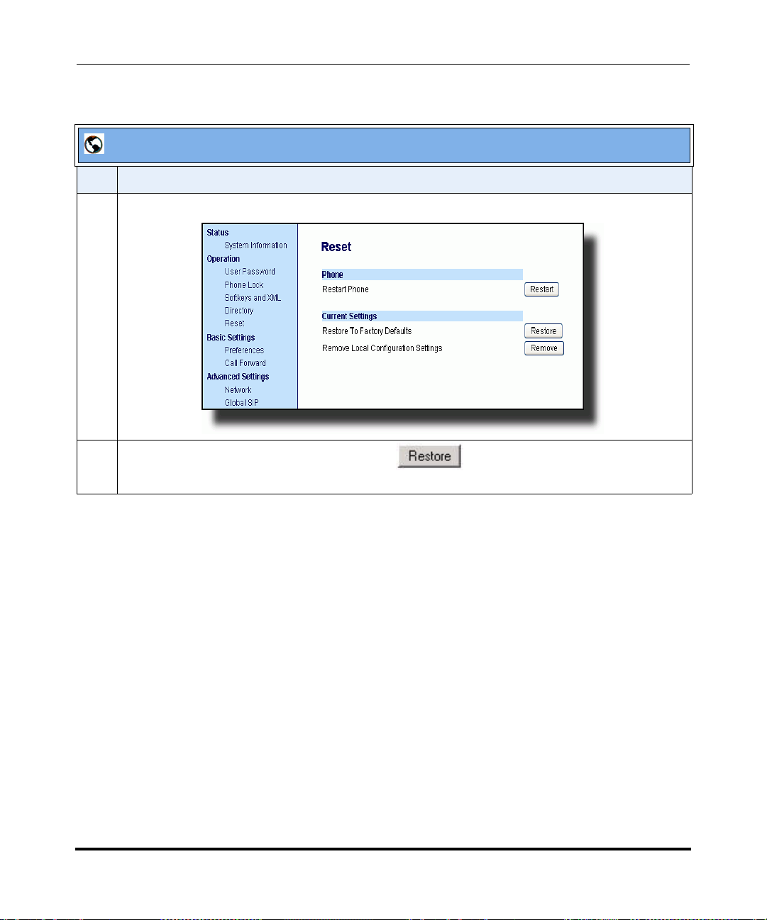
IP Phone Administrator Guide
Administrator Level Options
Settings Factory Defaults Using the Aastra Web UI
Aastra Web UI
Step Action
1 Click on Operation->Reset->Current Settings.
2 In the "Restore to Factory Defaults" field, click .
Administrator Options
3-16 41-001160-00, Release 2.1, Rev 04
This restores all factory defaults, and removes any saved configuration and directory list files.
Page 75

Administrator Options
Administrator Level Options
Erasing the Phone’s Local Configuration
You can reset the IP Phone’s local configuration if required. The local
configuration is the last updated configuration you performed using the IP Phone
UI or the Aastra Web UI. Performing this action results in losing all recently
user-modified settings. For more information about local configuration, see
Chapter 1, the section, “Configuration File Precedence” on page 1-22.
Erasing the Phone’s Local Configuration Using the IP Phone UI
IP Phone UI
Step Action
1 Press on the phone to enter the Options List.
2Select Administrator Menu and enter your Administrator Password (default is 22222).
3Select Erase Local Config.
4 For 53i:
The “Erase local config?” prompt displays.
Press # to confirm.
Administrator Options
For 55i/57i/57i CT:
The “Erase local config?” prompt displays.
Press Erase to confirm.
41-001160-00, Release 2.1, Rev 04 3-17
Page 76

IP Phone Administrator Guide
Administrator Level Options
Erasing the Phone’s Local Configuration Using the Aastra Web UII
Aastra Web UI
Step Action
1 Click on Operation->Reset->Current Settings.
2 In the "Remove Local Configuration Settings" field, click .
Administrator Options
3-18 41-001160-00, Release 2.1, Rev 04
This removes the last customized configuration settings made on the phone.
Page 77

Administrator Options
Administrator Level Options
Basic Settings
An Administrator has access to specific Basic Setting options to configure and
manage the IP Phone in the network. The following sections identify the options
available to an Administrator only, or where indicated, to a User and
Administrator. These tables also identify whether you can configure them using
the Aastra Web UI, IP Phone UI, or the configuration files.
General Settings
Parameter in
Aastra Web UI
Local Dial Plan sip dial plan A dial plan that describes the number and pattern of
Send Dial Plan
Terminator
Parameter in
Configuration Files Description
digits that a user dials to reach a particular telephone
number.
For more information on this feature, see “Local Dial
Plan” on page 5-30.
sip dial plan terminator Allows you to enable or disable a dial plan terminator.
When you configure the dial plan on the phone to use
a dial plan terminator (such as the pound symbol (#)),
the phone waits 4 or 5 seconds after you pick up the
handset or after dialing the number on the keypad
before making the call.
Administrator Options
For more information on this feature, see “SIP Dial
Plan Terminator” on page 5-32.
Digit Timeout sip digit timeout Represents the time, in seconds, to configure the
timeout between consecutive key presses.
For more information on this feature, see. “Digit
Timeout” on page 5-32.
41-001160-00, Release 2.1, Rev 04 3-19
Page 78

IP Phone Administrator Guide
Administrator Level Options
Parameter in
Aastra Web UI
Park Call
Note: This option can
be set by both Users
and Administrators.
Pick Up Parked Call
Note: This option can
be set by both Users
and Administrators.
Administrator Options
Suppress DTMF
Playback
Note: This option can
be set by both Users
and Administrators.
Display DTMF Digits
Note: This option can
be set by both Users
and Administrators.
Call Waiting
Parameter in
Configuration Files Description
sprecode The parking of a live call to a specific extension.
This feature on the Basic Preferences screen is
available on the 55i, 57i, and 57i CT only.
To configure the Park feature on a global basis, see
Chapter 5, the section, “Park Calls/Pick Up Parked
Calls” on page 35.
To configure the Park feature on a key, see Chapter 5,
the section, “Park/Pick Up Key” on page 5-153.
pickupsprecode Picking up a parked call at the specified extension.
This feature on the Basic Preferences screen is
available on the 55i, 57i, and 57i CT only.
To configure the Pickup feature on a global basis, see
Chapter 5, the section, “Park Calls/Pick Up Parked
Calls” on page 35.
To configure the Pickup feature on a key, see Chapter
5, the section, “Park/Pick Up Key” on page 5-153.
suppress dtmf playback Enables and disables suppression of DTMF playback
when a number is dialed from the softkeys or
programmable keys.
For more information on this feature, see.
“Suppressing DTMF Playback” on page 5-39.
display dtmf digits Enables and disables the display of DTMF digits on
the IP phone display during a connected state.
For more information on this feature, see. “Display
DTMF Digits” on page 5-41.
call waiting Enable or disables Call Waiting on the IP Phone.
Note: This option can
be set by both Users
and Administrators.
3-20 41-001160-00, Release 2.1, Rev 04
For more information on this feature, see. “Call
Waiting/Call Waiting Tone” on page 5-43.
Page 79

Administrator Options
Administrator Level Options
Parameter in
Aastra Web UI
Play Call Waiting Tone
Note: This option can
be set by both Users
and Administrators.
Stuttered Dial Tone
Note: This option can
be set by both Users
and Administrators.
XML Beep Support
Note: This option can
be set by both Users
and Administrators.
Status Scroll Delay
(seconds)
Note: This option can
be set by both Users
and Administrators.
Incoming Call Interrupts
Dialing
Note: This option can
be set by both Users
and Administrators.
Goodbye Key Cancels
Incoming Call
Parameter in
Configuration Files Description
call waiting tone Enable or disables the playing of a call waiting tone
when a caller is on an active call and a new call comes
into the phone.
For more information on this feature, see. “Call
Waiting/Call Waiting Tone” on page 5-43.
stutter disabled Enable or disables the playing of a stuttered dial tone
when there is a message waiting on the IP phone.
For more information on this feature, see. “Stuttered
Dial Tone” on page 5-46.
xml beep notification Enables or disables the playing of a beep to indicate a
status on the phone. When the phone receives a
status message, the BEEP notifies the user that the
message is displaying.
For more information on this feature, see “XML Beep
Support” on page 5-48.
xml status scroll delay Allows you to set the time delay, in seconds, between
the scrolling of each status message on the phone.
For more information on this feature, see “Status
Scroll Delay” on page 5-50.
incoming call interrupts
dialing
goodbye key cancels
incoming call
Enable or disables how the phone handles incoming
calls while the phone is dialing out. For more
information on this feature, see “Incoming Call
Interrupts Dialing” on page 5-52.
Enable or disables the behavior of the Goodbye Key
on the IP phone.
Administrator Options
Note: This option can
be set by both Users
and Administrators.
41-001160-00, Release 2.1, Rev 04 3-21
For more information on this feature, see “Goodbye
Key Cancels Incoming Call” on page 5-54.
Page 80

IP Phone Administrator Guide
Administrator Level Options
Parameter in
Aastra Web UI
UPnP Mapping Lines
Note: This option can
be set by both Users
and Administrators.
Message Waiting
Indicator Line
Note: This option can
be set by both Users
and Administrators.
Parameter in
Configuration Files Description
upnp mapping lines Enables or disables the use of Universal Plug and
Play (UpnP) on a specific line on the IP phone.
For more information on this feature, see “UPnP
Mapping Lines (for remote phones)” on page 5-56.
mwi led line Allows you to enable the Message Waiting Indicator
(MWI) on a single line or on all lines on the phone. For
example, if you set this parameter to 3, the LED
illuminates if a voice mail is pending on line 3. If you
set this parameter to 0, the LED illuminates if a voice
mail is pending on any line on the phone (lines 1
through 9).
For more information on this feature, see “Message
Waiting Indicator Line” on page 5-58.
Incoming/Outgoing Intercom Calls
The Incoming/Outgoing Intercom Call settings on the IP Phone specify
Administrator Options
whether the IP phone or the server is responsible for notifying the recipient that an
Intercom call is being placed. These settings also specify the prefix code for
server-side Intercom calls, and specifies the configuration to use when making the
Intercom call
.
Parameter in
Aastra Web UI
Incoming Intercom Settings (all models)
Auto-Answer
Note: This option can
be set by both Users
and Administrators.
3-22 41-001160-00, Release 2.1, Rev 04
Parameter in
Configuration Files
sip allow auto answer Enables or disables the IP phone to allow automatic
answering for an Intercom call. If auto-answer is
enabled on the IP phone, the phone plays a tone to
alert the user before answering the intercom call. If
auto-answer is disabled, the phone rejects the
incoming intercom call and sends a busy signal to the
caller.
For more information on this feature, see “Incoming/
Outgoing Intercom with Auto-Answer and Barge In” on
page 5-60.
Description
Page 81

Administrator Options
Administrator Level Options
Parameter in
Aastra Web UI
Microphone Mute
Note: This option can
be set by both Users
and Administrators.
Play Warning Tone
Note: This option can
be set by both Users
and Administrators.
Allow Barge In
Note: This option can
be set by both Users
and Administrators.
Outgoing Intercom Settings (55i, 57i, and 57i CT only))
Type sip intercom type Determines whether the IP phone or the server is
Parameter in
Configuration Files Description
sip intercom mute mic Enables or disables the microphone on the IP phone
for Intercom calls made by the originating caller.
For more information on this feature, see “Incoming/
Outgoing Intercom with Auto-Answer and Barge In” on
page 5-60.
sip play warning tone Enables or disables a warning tone to play when the
phone receives an incoming intercom call on an active
line.
For more information on this feature, see “Incoming/
Outgoing Intercom with Auto-Answer and Barge In” on
page 5-60.
sip intercom allow barge inEnable or disables how the phone handles incoming
intercom calls while the phone is on an active call.
For more information on this feature, see “Incoming/
Outgoing Intercom with Auto-Answer and Barge In” on
page 5-60.
responsible for notifying the recipient that an Intercom
call is being placed. Applicable settings are
Phone-Side, Server-Side, OFF.
Administrator Options
For more information on this feature, see “Incoming/
Outgoing Intercom with Auto-Answer and Barge In” on
page 5-60.
41-001160-00, Release 2.1, Rev 04 3-23
Page 82

IP Phone Administrator Guide
Administrator Level Options
Parameter in
Aastra Web UI
Prefix Code sip intercom prefix code The prefix to add to the phone number for server-side
Line sip intercom line Specifies the line for which the IP phone uses the
Parameter in
Configuration Files Description
outgoing Intercom calls. This parameter is required for
all server-side Intercom calls.
For more information on this feature, see “Incoming/
Outgoing Intercom with Auto-Answer and Barge In” on
page 5-60.
configuration from, when making the Intercom call.
The IP phone uses the first available line for physically
making the call but uses the configuration from the line
you set for this parameter.
Note: The "sip intercom type" parameter must be set
with the Server-Side option to enable the "sip
intercom line" parameter.
For more information on this feature, see “Incoming/
Outgoing Intercom with Auto-Answer and Barge In” on
page 5-60.
Administrator Options
3-24 41-001160-00, Release 2.1, Rev 04
Page 83

Administrator Options
Administrator Level Options
Key Mapping
Administrator Options
Parameter in
Aastra Web UI
Map Redial Key To map redial key to Sets the Redial key as a speeddial key if a value is
Map Conf Key To map conf key to Sets the Conf key as a speeddial key if a value is
Parameter in
Configuration Files Description
entered for this parameter. If you leave this parameter
blank, the Redial key returns to its original
functionality.
Note: If you configure the Redial key for speeddialing
on the 57i CT Base Station, the Redial key on the 57i
CT handset retains its original functionality. The
Redial key on the handset is not configured for
speeddial.
For more information on this feature, see “Key
Mapping” on page 5-66.
entered for this parameter. If you leave this parameter
blank, the Conf key returns to its original functionality.
Note: If you configure the Conf key for speeddialing
on the 57i CT Base Station, the Conf key on the 57i
CT handset retains its original functionality. The Conf
key on the handset is not configured for speeddial.
For more information on this feature, see “Key
Mapping” on page 5-66.
41-001160-00, Release 2.1, Rev 04 3-25
Page 84

IP Phone Administrator Guide
Administrator Level Options
Ring Tones
Parameter in
IP Phone UI
Tone Set
Note: This option can
be set by both Users
and Administrators.
Ring Tone
Note: This option can
be set by both Users
and Administrators.
N/A LineN
Parameter in
Aastra Web UI
Tone Set tone set Globally sets a tone set for a
Global Ring Tone ring tone Globally sets the type of ring tone
Note: This option can
be set by both Users
and Administrators.
Parameter in
Configuration Files Description
lineN ring tone Sets the type of ring tone on the
Administrator Options
Priority Alerting Settings
specific country
For more information on this
feature, see “Ring Tones and
Tone Sets” on page 5-70.
on the IP phone. Ring tone can
be set to one of six distinct rings.
For more information on this
feature, see “Ring Tones and
Tone Sets” on page 5-70.
IP phone on a per-line basis.
Ring tone can be set to one of six
distinct rings.
For more information on this
feature, see “Ring Tones and
Tone Sets” on page 5-70.
Parameter in
Aastra Web UI
Enable Priority Alerting priority alerting enabled Enables and disables distinctive ringing on the IP
Group alert group When an "alert group" keyword appears in the header
3-26 41-001160-00, Release 2.1, Rev 04
Parameter in
Configuration Files
Description
phone for incoming calls and call-waiting calls.
For more information on this feature, see “Priority
Alerting” on page 5-75.
of the INVITE request, the configured Bellcore ring
tone is applied to the IP phone.
For more information on this feature, see “Priority
Alerting” on page 5-75.
Page 85

Administrator Options
Administrator Level Options
Parameter in
Aastra Web UI
External alert external When an "alert external" keyword appears in the
Internal alert internal When an "alert-internal" keyword appears in the
Emergency alert emergency When an "alert emergency" keyword appears in the
Priority alert priority When an "alert priority" keyword appears in the
Auto Call Distribution alert auto call distribution When an "alert-acd" keyword appears in the header of
Parameter in
Configuration Files Description
header of the INVITE request, the configured Bellcore
ring tone is applied to the IP phone.
For more information on this feature, see “Priority
Alerting” on page 5-75.
header of the INVITE request, the configured Bellcore
ring tone is applied to the IP phone.
For more information on this feature, see “Priority
Alerting” on page 5-75.
header of the INVITE request, the configured Bellcore
ring tone is applied to the IP phone.
For more information on this feature, see “Priority
Alerting” on page 5-75.
header of the INVITE request, the configured Bellcore
ring tone is applied to the IP phone.
For more information on this feature, see “Priority
Alerting” on page 5-75.
the INVITE request, the configured Bellcore ring tone
is applied to the IP phone.
Administrator Options
For more information on this feature, see “Priority
Alerting” on page 5-75.
Community 1 thru
Community 4
41-001160-00, Release 2.1, Rev 04 3-27
alert community 1
alert community 2
alert community 3
alert community 4
When an "alert community-#” keyword appears in the
header of the INVITE request, the configured Bellcore
ring tone is applied to the IP phone. Available Bellcore
tones are:
0 Normal ringing (default)
1 Bellcore-dr2
2 Bellcore-dr3
3 Bellcore-dr4
4 Bellcore-dr5
5 Silent
For more information on this feature, see “Priority
Alerting” on page 5-75.
Page 86

IP Phone Administrator Guide
Administrator Level Options
Directed Call Pickup (DCP)
Parameter in
Aastra Web UI
Directed Call Pickup directed call pickup Enables or disables the use of "directed call pickup"
Directed Call Pickup
Prefix
Play a Ring Splash play a ring splash Enables or disables the playing of a short "ring splash
Administrator Options
Parameters in
Configuration Files Description
feature.
For more information on this feature, see “Directed
Call Pickup (BLF or XML Call Interception)” on
page 5-81.
directed call pickup
prefix
Allows you to specify a prefix to use for "directed call
pickup" that you can use with a BLF or BLF List
softkey.
For more information on this feature, see “Directed
Call Pickup (BLF or XML Call Interception)” on
page 5-81.
tone" when there is an incoming call on the BLF
monitored extension. If the host tone is idle, the tone
plays a "ring splash".
For more information on this feature, see “Directed
Call Pickup (BLF or XML Call Interception)” on
page 5-81.
3-28 41-001160-00, Release 2.1, Rev 04
Page 87

Administrator Options
Administrator Level Options
Auto Call Distribution (ACD) Settings
Administrator Options
Parameter in
Aastra Web UI
Auto Available acd auto available Enables or disables the use of the ACD Auto-Available
Auto Available Timer acd auto available timer Specifies the length of time, in seconds, before the IP
Parameters in
Configuration Files Description
Timer.
For more information on this feature, see “Automatic
Call Distribution (ACD) (for Sylantro Servers)” on
page 5-122.
phone status switches back to “available.”
For more information on this feature, see “Automatic
Call Distribution (ACD) (for Sylantro Servers)” on
page 5-122.
Time and Date
Parameter in
IP Phone UI
Time Format
Note: This option can
be set by both Users
and Administrators.
Date Format
Note: This option can
be set by both Users
and Administrators.
Parameter in
Aastra Web UI
Time Format time format This parameter changes the time
Date Format date format This parameter allows the user to
Parameters in
Configuration Files
Description
to 12 hour or 24 hour format. Use
“0” for the 12 hour format and “1”
for the 24 hour format.
For more information on this
feature, see “Time and Date” on
page 5-17.
change the date to various
formats
For more information on this
feature, see “Time and Date” on
page 5-17.
41-001160-00, Release 2.1, Rev 04 3-29
Page 88

IP Phone Administrator Guide
Administrator Level Options
Language
Parameter in
Aastra Web UI
WebPage Language
Note: This option can
be set by both Users
and Administrators.
Administrator Options
Language 1 thru
Language
Parameter in
Configuration Files Description
language The language you want to display in the IP Phone UI
and the Aastra Web UI.
Valid values for 53i, 55i, 57i are:
0 (English)
1 (French - Canadian)
2 (Spanish - Mexican)
3 (German)
4 (Italian)
Valid values for 57i CT are:
0 (English)
1 (French - Canadian)
2 (Spanish - Mexican)
Note: All languages may not be available for
selection. The available languages are dependant on
the language packs currently loaded to the IP phone.
For more information about loading language packs,
see “Loading Language Packs” on page 5-21.
For more information on this feature, see “Language”
on page 5-21.
language N The language pack you want to load to the IP phone.
Valid values are:
lang_fr-ca.txt
lang_es.txt
lang_de.txt
lang_it.txt
Notes:
1. The languages packs you load are dependant on
available language packs from the configuration
server.
2. You must reboot the phone to load a language
pack.
For more information about loading language packs,
see “Loading Language Packs” on page 5-21.
For more information on this feature, see “Language”
on page 5-21.
3-30 41-001160-00, Release 2.1, Rev 04
Page 89

Administrator Options
Administrator Level Options
Network Settings
The following paragraphs describe the network parameters you can configure on
the IP phone. Network settings are in two categories:
• Basic network settings
• Advanced network settings
Administrator Options
Note: Specific parameters are configurable using the Aastra Web UI only
and are indicated where applicable.
41-001160-00, Release 2.1, Rev 04 3-31
Page 90

IP Phone Administrator Guide
Administrator Level Options
Basic Network Settings
If Dynamic Host Configuration Protocol (DHCP) is enabled, the IP phone
automatically configures all of the Network settings. If the phone cannot populate
the Network settings, or if DHCP is disabled, you can set the Network options
manually.
Parameter In
IP Phone UI
DHCP DHCP dhcp Enables or disables DHCP.
Administrator Options
IP Address IP Address ip IP address of the IP phone. To
Parameter in
Aastra Web UI
Parameters in
Configuration Files
Description
Enabling DHCP populates the
required network information. The
DHCP server serves the network
information that the IP phone
requires. If the IP phone is unable to
get any required information, then
you must enter it manually. DHCP
populates the following network
information:
IP Address, Subnet Mask, Gateway,
Broadcast Address, Domain Name
Servers (DNS), TFTP, HTTP
HTTPS, and FTP servers, and
Timer Servers.
Note: For DHCP to automatically
populate the IP address or qualified
domain name for the TFTP server,
your DHCP server must support
Option 66.
For more information, see “DHCP”
on page 4-4.
assign a static IP address, disable
DHCP.
For more information, see
“Configuring Network Settings
Manually” on page 4-8.
3-32 41-001160-00, Release 2.1, Rev 04
Page 91

Administrator Options
Administrator Level Options
Parameter In
IP Phone UI
Subnet Mask Subnet Mask subnet mask Subnet mask defines the IP address
Gateway Gateway default gateway The IP address of the network’s
Primary DNS Primary DNS dns1 Primary domain name server IP
Parameter in
Aastra Web UI
Parameters in
Configuration Files Description
range local to the IP phone. To
assign a static subnet mask, disable
DHCP.
For more information, see
“Configuring Network Settings
Manually” on page 4-8.
gateway or default router IP
address. To assign a static Gateway
IP address, disable DHCP.
For more information, see
“Configuring Network Settings
Manually” on page 4-8.
address. For any of the IP address
settings on the IP phone a domain
name value can be entered instead
of an IP address. With the help of
the domain name servers the
domain names for such parameters
can then be resolved to their
corresponding IP addresses.
To assign static DNS addresses,
disable DHCP.
Administrator Options
Note: If a host name is configured
on the IP phone, you must also set
a DNS.
For more information, see
“Configuring Network Settings
Manually” on page 4-8.
41-001160-00, Release 2.1, Rev 04 3-33
Page 92

IP Phone Administrator Guide
Administrator Level Options
Parameter In
IP Phone UI
Secondary DNS Secondary DNS dns2 A service that translates domain
LAN Port LAN Port ethernet port 0 The send (TX) and receive (RX)
PC Port PC Port ethernet port 1 The send (TX) and receive (RX)
Parameter in
Aastra Web UI
Parameters in
Configuration Files Description
names into IP addresses. To assign
static DNS addresses, disable
DHCP.
For more information, see
“Configuring Network Settings
Manually” on page 4-8.
method to use on Ethernet port 0
(LAN Port) to transmit and receive
data over the LAN.
For more information, see Chapter
4, “Configuring LAN and PC Port
Negotiation” on page 4-11.
method to use on Ethernet port 1
(PC Port) to transmit and receive
data to your PC.
Administrator Options
For more information, see Chapter
4, “Configuring LAN and PC Port
Negotiation” on page 4-11.
3-34 41-001160-00, Release 2.1, Rev 04
Page 93

Administrator Options
Administrator Level Options
Advanced Network Settings
Administrator Options
Parameter In
IP Phone UI
UPnP UPnP upnp manager Enables or disables Universal Plug
N/A N/A upnp gateway IP address or fully qualified Domain
NAT IP NAT IP sip nat ip IP address the network device that
Parameter in
Aastra Web UI
Parameters in
Configuration Files Description
and Play (UpnP) on the IP phone. If
you set this parameter to “0”, you
can manually configure NAT on the
IP phone and the UPnP manager
will not start.
For more information, see Chapter
4, “Universal Plug and Play (UPnP)
(for remote phones)” on page 4-27.
Name of the Internet gateway or
router. This parameter stores the IP
address of the gateway or router in
the event that only non-default
UPnP gateways get discovered on
the network. The UPnP port
mappings are saved to this IP
address so even if the phone
reboots, it will still have the correct
port mappings.
For more information, see Chapter
4, “Universal Plug and Play (UPnP)
(for remote phones)” on page 4-27.
enforces NAT.
For more information, see Chapter
4, “Configuring NAT Address and
Port (optional)” on page 4-21.
NAT SIP Port NAT SIP Port sip nat port Port number of the network device
that enforces NAT.
For more information, see Chapter
4, “Configuring NAT Address and
Port (optional)” on page 4-21.
41-001160-00, Release 2.1, Rev 04 3-35
Page 94

IP Phone Administrator Guide
Administrator Level Options
Parameter In
IP Phone UI
NAT RTP Port NAT RTP Port sip nat rtp port Indicates the port through which the
Nortel NAT Nortel NAT Traversal
Administrator Options
N/A Nortel NAT Timer
Parameter in
Aastra Web UI
Enabled
(seconds)
Parameters in
Configuration Files Description
RTP packets are sent. This value
must specify the beginning of the
RTP port range on the gateway or
router.
The RTP port is used for sending
DTMF tones and for the audio
stream. Your network administrator
may close some ports for security
reasons. You may want to use this
parameter to send RTP data using a
different port.
For more information, see Chapter
4, “Configuring NAT Address and
Port (optional)” on page 4-21.
sip nortel nat support Enables or disables the phone to
operate while connected to a
network device that enforces NAT.
For more information, see Chapter
4, “Configuring Nortel NAT
(optional)” on page 4-18.
sip nortel nat timer The interval, in seconds, that the
phone sends SIP ping requests to
the Nortel proxy.
For more information, see Chapter
4, “Configuring Nortel NAT
(optional)” on page 4-18.
3-36 41-001160-00, Release 2.1, Rev 04
Page 95

Administrator Options
Administrator Level Options
Parameter In
IP Phone UI
N/A NTP Time Servers time server disabled Enables or disables the time server.
N/A Time Servers 1, 2,
Client Method HTTPS Client
Parameter in
Aastra Web UI
and 3
Method
Parameters in
Configuration Files Description
This parameter affects the time
server1, time server2, and time
server3 parameters. Setting this
parameter to 0 allows the use of the
configured Time Server(s). Setting
this parameter to 1 prevents the use
of the configured Time Server(s).
For more information, see Chapter
4, “Network Time Servers” on
page 4-42.
time server1
time server2
time server3
time server4
https client method Defines the security method that the
The 1st, 2nd, 3rd, and 4th time
server's IP address or qualified
domain name. If the time server is
enabled, the value for time server1
will be used to request the time
from.
For more information, see Chapter
4, “Network Time Servers” on
page 4-42.
client advertises to the server during
the Secure Socket Layer (SSL)
handshake. Available options are:
Administrator Options
TLS 1.0 - Transport Layer Security
version 1 (TLS 1.0) is a protocol that
ensures privacy between
communicating applications and
their users on the Internet. TLS is
the successor to SSL.
SSL 3.0 - Secure Socket Layer
version 3 (SSL 3.0) is a
commonly-used protocol for
managing the security of a message
transmission on the Internet.
For more information, see Chapter
4, “HTTPS Client/Server
Configuration” on page 4-23.
41-001160-00, Release 2.1, Rev 04 3-37
Page 96

IP Phone Administrator Guide
Administrator Level Options
Parameter In
IP Phone UI
HTTPS HTTPS Server -
XML HTTP POSTs HTTPS Server -
Parameter in
Aastra Web UI
Redirect HTTP to
HTTPS
Block XML HTTP
POSTs
Parameters in
Configuration Files Description
https redirect http get Allows or disallows redirection from
https block http post xml Enables or disables the blocking of
Administrator Options
the HTTP server to the HTTPS
server.
For more information, see Chapter
4, “HTTPS Client/Server
Configuration” on page 4-23.
XML scripts from HTTP POSTs.
Some client applications use HTTP
POSTs to transfer XML scripts. The
phones’s HTTP server accepts
these POSTs even if server
redirection is enabled, effectively
bypassing the secure connection.
When this parameter is enabled
(blocking is enabled), receipt of an
HTTP POST containing an XML
parameter header results in the
following response:
“403 Forbidden”. This forces the
client to direct the POSTs to the
HTTPS server through use of the
“https://” URL.
For more information, see Chapter
4, “HTTPS Client/Server
Configuration” on page 4-23.
3-38 41-001160-00, Release 2.1, Rev 04
Page 97

Administrator Options
Administrator Level Options
Type of Service (ToS), DSCP (53i)
Networks settings include Type of Service (ToS) and Differentiated Services Code
Point (DSCP) for the 53i IP phone.
Administrator Options
Parameter In
IP Phone UI
Type of Service
SIPt
Type of Service
RTP
Type of Service
RTCP
Parameter in
Aastra Web UI
SIP tos sip The Differentiated Services Code
RTP tos rtp The Differentiated Services Code
RTCP tos rtcp The Differentiated Services Code
Parameters in
Configuration Files Description
Point (DSCP) for SIP packets.
For more information, see Chapter
4, “Type of Service (ToS), Quality of
Service (QoS), and DiffServ QoS”
on page 4-31.
Point (DSCP) for RTP packets.
For more information, see Chapter
4, “Type of Service (ToS), Quality of
Service (QoS), and DiffServ QoS”
on page 4-31.
Point (DSCP) for RTCP packets.
For more information, see Chapter
4, “Type of Service (ToS), Quality of
Service (QoS), and DiffServ QoS”
on page 4-31.
41-001160-00, Release 2.1, Rev 04 3-39
Page 98

IP Phone Administrator Guide
Administrator Level Options
VLAN
You can enable or disable VLAN and set specific VLAN IDs and priorities under
Network Settings.
Parameter In
IP Phone UI
Global Settings
VLAN Enable VLAN Enable tagging enabled Enables or disables VLAN on the IP
Other Priority Priority, Non-IP
LAN Port Settings (Port 0)
Administrator Options
Phone VLAN ID VLAN ID VLAN id VLAN is a feature on the IP phone
Parameter in
Aastra Web UI
Packet
Parameters in
Configuration Files Description
phones.
For more information, see Chapter
4, “Virtual LAN (optional)” on
page 4-31.
priority non-ip Specifies the priority value for
non-IP packets.
For more information, see Chapter
4, “Virtual LAN (optional)” on
page 4-31.
that allows for multiple logical
Ethernet interfaces to send
outgoing RTP packets over a single
physical Ethernet as described in
IEEE Std 802.3. On the IP phone,
you configure a VLAN ID that
associates with the physical
Ethernet Port 0.
For more information, see Chapter
4, “Virtual LAN (optional)” on
page 4-31.
3-40 41-001160-00, Release 2.1, Rev 04
Page 99

Administrator Options
Administrator Level Options
Parameter In
IP Phone UI
SIP Priority
RTP Priority
RTCP Priority
Parameter in
Aastra Web UI
SIP Priority
RTP Priority
RTCP Priority
Parameters in
Configuration Files Description
tos priority map This parameter is based on the
Type of Service (ToS), Differentiated
Services Code Point (DSCP) setting
for SIP (tos sip parameter), RTP
(tos rtp parameter) and RTCP (tos
rtcp parameter). It is the mapping
between the DSCP value and the
VLAN priority value for SIP, RTP,
and RTCP packets.
You enter the tos priority map value
as follows:
(DSCP_1,Priority_1)(DSCP_2,Priori
ty_2).....(DSCP_64,Priority_64)
where the DSCP value range is
0-63 and the priority range is 0-7.
Mappings not enclosed in
parentheses and separated with a
comma, or with values outside the
ranges, are ignored.
For more information, see Chapter
4, “Virtual LAN (optional)” on
page 4-31.
Administrator Options
41-001160-00, Release 2.1, Rev 04 3-41
Page 100

IP Phone Administrator Guide
Administrator Level Options
Parameter In
IP Phone UI
PC Port Settings (Port 1)
PC Port VLAN ID VLAN ID VLAN id port 1 Specifies the VLAN ID used to pass
Administrator Options
PC Port Priority Priority QoS eth port 1 priority Specifies the priority value used for
Parameter in
Aastra Web UI
Parameters in
Configuration Files Description
packets through to a PC via Port 1.
Note: If you set the PC Port VLAN
ID (Port 1) to 4095, all untagged
packets are sent to this port. The
following is an example of
configuring the phone on a VLAN
where all untagged packets are sent
to the passthrough port.
Example
You enable tagging on the LAN Port
(VLAN id) as normal but set the PC
Port (VLAN id port 1) to 4095. The
following example sets the phone to
be on VLAN 3 on the LAN Port but
the PC Port is configured as
untagged.
tagging enabled: 1
VLAN id: 3
VLAN id port 1: 4095
For more information, see Chapter
4, “Virtual LAN (optional)” on
page 4-31.
passing VLAN packets through to a
PC via Port 1.
For more information, see Chapter
4, “Virtual LAN (optional)” on
page 4-31.
3-42 41-001160-00, Release 2.1, Rev 04
 Loading...