


AAON®
RM SERIES
HEATING • COOLING & COMBINATION ROOFTOP UNITS
INSTALLATION
INSTRUCTION
MANUAL
▲! WARNING
If the information in this manual is not followed exactly, a fire or explosion may result causing property damage, personal injury or loss of life.
FOR YOUR SAFETY
DO NOT STORE OR USE GASOLINE OR OTHER FLAMMABLE VAPORS AND LIQUIDS IN THE VICINITY OF THIS OR ANY OTHER APPLIANCE.
7-2003
FOR YOUR SAFETY
WHAT TO DO IF YOU SMELL GAS
•EXTINGUISH ANY OPEN FLAME.
•DO NOT TOUCH ANY ELECTRICAL SWITCH.
•DO NOT TRY TO LIGHT ANY APPLIANCE.
•DO NOT USE ANY PHONE IN YOUR BUILDING.
•IMMEDIATELY CALL YOUR GAS SUPPLIER FROM A NEIGHBOR'S PHONE.
FOLLOW THE GAS SUPPLIER'S INSTRUCTIONS.
•IF YOU CANNOT REACH YOUR GAS SUPPLIER, CALL THE FIRE DEPARTMENT.
1

AAON®
TABLE OF CONTENTS
SECTION |
PAGE NUMBER |
GENERAL DESCRIPTION …………………………………………………………………………… 03
Unpacking
Certification
Codes and Ordinances
OWNER'S INFORMATION …………………………………………………………………………… 04
HEATING / COOLING SYSTEMS …………………………………………………………………… 05
INSTALLATION ………………………………………………………………………………………… 06 Setting the Curb / Unit ………………………………………………………………………… 07 Service Clearances
Outside Air Hood………………………………………………………………………………… 08 Electrical
Gas Piping………………………………………………………………………………………… 09 Condensate Piping ……………………………………………………………………………… 10
GAS UNIT LIGHTING INSTRUCTIONS …………………………………………………………… 11
PERIODIC INSPECTION PROCEDURES ………………………………………………………… 12 Gas Heating, Cooling, Electric, Steam, Hot Water & Chilled Water Units
SERVICE, TROUBLE SHOOTING & MAINTENANCE ………………………………………… 14
Lubrication
Cleaning
FILTER INSTALLATION / REPLACEMENT ……………………………………………………… 15
SERVICING ……………………………………………………………………………………………… 16 Rooftop Unit Replacement Parts …………………………………………………………… 18
SEQUENCE OF OPERATIONS ……………………………………………………………………… 19 Heating
Cooling
Optional Economizer
VAV Systems …………………………………………………………………………………… 20 Power Exhaust Options
COMPRESSOR CHECKOUT PROCEDURE ……………………………………………………… 21
IGNITION CONTROL CHECKOUT PROCEDURE ……………………………………………… 22
FACTORY START-UP FORM ………………………………………………………………………… 23
Owner should pay particular attention to the words: NOTE, CAUTION AND WARNING.
NOTES are intended to clarify or make the installation easier. CAUTIONS are given to prevent equipment damage. WARNINGS are given to alert owner that personal injury and/or equipment damage may result if installation procedure is not handled properly.
It is the intent of AAON, Inc. to provide accurate and current specification information. However, in the interest of product improvement, AAON, Inc. reserves the right to change pricing, specifications and/or design of it's products without notice, obligation or liablity.
© 2003 AAON, Inc., all rights reserved throughout the world.
AAON & AAONAIRE are registered trademarks of AAON, Inc., Tulsa, OK.
R15690 (7-03)
2

The units are designed as self-contained heating, cooling or combination units for outdoor installation only, using the refrigerant shown on the rating plate, chilled water, natural or propane gas, electric resistance, steam or hot water.
UNPACKING
When received, the unit should be checked for damage that might have occurred in transit. If damage is found, it should be noted on the carrier's Freight Bill. A request for inspection by carrier's agent should be made in writing at once.
CERTIFICATION
GENERAL DESCRIPTION
▲! WARNING
Improper installation, adjustment, alteration, service or maintenance can cause property damage, personal injury or loss of life. Installation and service must be performed by a qualified installer, service agency
or the gas supplier.
NOTE: These units must not be used as a "construction heater" at any time during any phase of construction. Very low return air temperatures, harmful vapors, and misplacement of the filters will damage the unit and its efficiency.
•GAS HEAT MODELS
(a)Design Certified as a forced air furnace with or without cooling unit.
(b)Certified for outdoor installation only.
(c)Certified for installation on combustible roof with a minimum of 12" high curb.
(d)Certified with heat exchanger located downstream from evaporator coil.
•STEAM OR HOT WATER HEAT MODELS
(a)Certified as a forced air furnace with or without cooling unit.
(b)Certified for outdoor installation only.
(c)Certified for installation on combustible roof with a minimum of 12" high curb.
(d)ARI certified hot water coils.
•ELECTRIC HEAT MODELS
(a)Certified as an electric warm air furnace with or without cooling unit.
(b)Certified for outdoor installation only.
(c)Certified for installation on combustible roof with a minimum of 12" high curb.
•COOLING MODELS
(a)Certified as a commercial central air-conditioner with or without electrically operated compressor.
(b)Certified for outdoor installation only.
(c)Certified for installation on combustible roof with a minimum of 12" high curb.
(d)ARI certified coils.
CODES AND ORDINANCES
System should be sized in accordance with National Warm Air Heating and Air Conditioning Association Literature, or the Guide of American Society of Heating, Refrigeration and Air Conditioning Engineers. The installation must conform with local building codes or, in the absence of local codes with (United States) National Fuel Gas Code "ANSI-Z223.1", (Canada) current CAN /
CGAB149.1 or . 2. Installation Codes for Gas Burning
Appliances and Equipment, current C.S.A. Standard C22.1, Canadian Electrical Code Part 1, and C.S.A. Standard B52 Mechanical Refrigeration Code, and Local Plumbing or Waste Water Codes.
▲! IMPORTANT
The Clean Air Act of 1990 bans the intentional venting of refrigerant (CFC's and HCFC's) as of July 1, 1992. Approved methods of recovery, recycling or reclaiming must be followed. Fines and/or incarceration may be levied for non-compliance.
3

OWNER'S INFORMATION
WARNING
Failure to observe the following instructions will result in premature failure of your system, and possible voiding of the warranty.
DIRECT EXPANSION (DX) COOLING UNITS
Never cut off the main power supply to the unit, except for complete shutdown. When power is cut off from the unit, compressors with crankcase heaters cannot prevent refrigerant migration. The compressor will cool down, and liquid refrigerant will accumulate in the compressor. The compressor is designed to pump only refrigerant gas and damage may occur when power is restored.
If power must be cut off for more than an hour, turn the thermostat system switch to "OFF", and leave it off until the main power switch has been turned on again for at least twenty four hours on units with compressor crankcase heaters. This will give the crankcase heater time to clear liquid accumulation out of the compressor before it is required to run.
Always control the system from the thermostat, or control panel, never at the main power supply (except in an emergency or complete shutdown of the system).
During the cooling season, if the air flow is reduced due to dirty air filters or other reasons, the cooling coils will get too cold and result in excessive liquid return to the compressor. As the liquid concentration accumulates, oil is washed out of the compressor, leaving it starved for lubrication.
The compressors must be on a minimum of 4 minutes and off for a minimum of 5 minutes. The cycle rate must not exceed 8 starts per hour.
THE COMPRESSOR LIFE WILL BE SERIOUSLY SHORTENED BY RESULTING REDUCED LUBRICATION, AND THE PUMPING OF EXCESS AMOUNTS
OF LIQUID OIL AND REFRIGERANT.
GAS OR ELECTRIC HEATING
The system is designed to heat a given amount of air each minute it operates. If the amount of air heated is greatly reduced (approximately 1/3 capacity), the heat exchanger / heater coil temperature will increase above acceptable level and result in shut down by a high temperature safety switch incorporated either in the heat exchanger or the heater area.
GAS HEAT UNITS - WARNING: If, due to safety switch shut off or gas supply shut off failure; ALWAYS CLOSE MANUAL GAS VALVE TO UNIT PRIOR TO ANY ELECTRICAL SERVICE.
PROLONGED OVERHEATING OF THE HEAT EXCHANGER WILL SHORTEN ITS LIFE.
WARNING: Improper installation, adjustment, alteration, service, or maintenance can cause property damage, personal injury or loss of life. Installation and service must be performed by a qualified installer, service agency or if gas fired units, the gas supplier. Refer to installation instructions provided with the unit and this manual.
CAUTION: While the following incorrect operations may not cause damage to the system, they will impair the performance, and may cause the built-in safety devices to cut the system off completely.
1.LOW AMBIENT OPERATION
The cooling section of a direct expansion (DX) unit
will not operate properly when the outdoor temperature is below 55°F. Outside air intake options are necessary if operation below 55°F is expected.
2.MULTIPLE UNIT OPERATION
When several units are used in conditioning the space, and any are combination heating-cooling units, all system thermostat switches must be set at either heating, cooling, or set at "off". Do not run part of a system switched to an opposite mode. Cooling only units should be switched to "off" at the thermostat during the heating season.
WIRING DIAGRAMS
A complete set of unit specific wiring diagrams in both ladder and point-to-point form are laminated in plastic and located inside the control compartment door.
CONDENSATE PIPING
A drain trap is to be connected to the drainpan. If codes require a condensate drain line, it should be the same pipe size as the drain nipple and should pitch downward toward drain.
The condensate drain pipe ("P" trap) is factory supplied and shipped in the control access compartment for field installation. An air break should be used with long runs of condensate lines.
▲! WARNING
Scroll compressors will be damaged by operation with the wrong rotation.
THE LOW PRESSURE SWITCH HAS BEEN
DISCONNECTED AFTER TESTING
AT THE FACTORY.
The wiring must be reconnected and proper rotation determined at the time of start-up by a qualified service technician using suction and discharge pressures gauges.
Any alteration should only be made at the unit power connection.
4
NORMAL OPERATION
HEATING
Set the thermostat system switch to "HEAT".
Set the thermostat fan switch to "AUTO" or "ON". Set the thermostat temperature at the desired point.
COOLING
Set the thermostat system switch to "COOL".
Set the thermostat fan switch to "AUTO" or "ON". Set the thermostat temperature at the desired point.
AIR CIRCULATION
Set the thermostat system switch to "OFF". Set the thermostat fan switch to "ON".
Do not change temperature setting.
With these settings, the air circulating blower will run continuously but the air will not be heated or cooled.
SYSTEM OFF
Set the thermostat system switch to "OFF". Set the thermostat fan switch to "AUTO". Do not change temperature setting.
With these settings, the system is shut down, with the exception of the control system power (24 Vac), and the crankcase heater of the compressor (approx. 60W).
DO NOT TURN OFF THE MAIN POWER SWITCH.
NIGHT AND VACANT WEEKEND OPERATION
To reduce the operation time during low load periods, it is recommended that the temperature setting be increased five degrees during these periods of the cooling season, and decreased ten degrees during the heating season.
GAS HEATING SYSTEM
The heating section is for use with natural gas supply pressure of 6" to 10.5" Water Column. The unit may also utilize propane gas with a supply pressure to the valve of 11" to 12" Water Column. The rating plate on the furnace must be inspected to make sure the unit is stamped for proper gas. A 1/8" pressure tap should be field supplied by the installer in the piping just ahead of the gas valve. The pressure tap on the outlet end of the gas valve can be checked to verify manifold pressure of 3.2" to 3.5" for natural gas.
Combustion air is supplied by a centrifugal blower which draws in outside air through a protected opening. This induced draft blower introduces the air to the burner tubes which assures even primary and secondary air flow.
All heating system and related safety controls are 100% tested on each unit prior to shipment.
HEATING & COOLING SYSTEMS
INSTALLATION IS TO BE ADJUSTED TO OBTAIN AN AIR TEMPERATURE RISE WITHIN THE RANGE SPECIFIED ON THE RATING PLATE.
The units are equipped with a direct spark ignition system which proves the burner operation during each call for heat. Power to the ignition control is 24 Vac to reduce hazards. Burner ignition is by a high intensity spark.
When heat is called for, the cooling system is inoperable except for the indoor blower motor. Heating is accomplished by firing gas into the heat exchanger assembly.
ELECTRIC HEATING SYSTEM
Heating is accomplished by passing electrical current through a specified amount of resistance heaters which produce the required heat. The indoor blower motor energizes at the same time as the heaters.
STEAM OR HOT WATER HEATING SYSTEM Heating is accomplished by passing steam or hot water through the steam or hot water coil assembly.
COOLING SECTION • DX
All direct expansion refrigeration systems are factory assembled, charged with refrigerant, tested and operated. On all units 8 ton and larger the refrigerant system includes multiple circuit evaporator and condenser coils providing two or more stages of cooling. These systems include liquid line filter driers, expansion valves and fully hermetic compressors. Compressors are equipped with a positive pressure forced lubrication system. The air cooled condenser coil(s) are constructed of copper tubes and mechanically bonded aluminum fins and air is pulled through by propeller fans. The evaporator coil is draw through type constructed of copper tubes and mechanically bonded aluminum fins.
The refrigeration section of these appliances has been found acceptable with applicable provisions of "ANSI / UL 1995" and current "C.S.A. Standard C22.2" by E.T.L.
NOTE: Crankcase Heater Operation
Some units are equipped with a compressor crankcase heater, which should be energized at least 24 hours prior to setting the thermostat for cooling operation.
COOLING SECTION • CHILLED WATER or NON-COMPRESSORIZED UNIT
Chilled water or non-compressorized units have factory installed coils. Systems are provided with internal header connections for field piping.
Coils are constructed of copper tubes and mechanically bonded aluminum fins.
5

INSTALLATION
▲! CAUTION
If outside air is in contact with the bottom of the unit, the unit must have the bottom insulation option or be field insulated.
DO NOT DRILL OR PUNCH HOLES IN BASE OF UNIT FROM INSIDE THE UNIT OR FROM BELOW TO ATTACH DUCTWORK. LEAKING MAY OCCUR IF UNIT BASE IS PUNCTURED.
SEE DETAIL "A"
SECTIONAL VIEW OF UNIT ON ROOF CURB
GASKET
DUCT RAIL
|
|
|
|
|
|
COUNTER |
||
|
|
WOOD |
|
FLASHING * |
||||
|
|
|
|
|
CANT STRIP * |
|||
|
|
NAILER * |
|
|
|
|||
|
|
|
|
|
|
|||
DUCT |
|
RIGID |
|
|
|
|
ROOFING |
|
|
|
|
|
|
MATERIAL* |
|||
|
|
|
|
|||||
|
INSULATION * |
|
|
|||||
FLEX |
|
|
|
|
|
|||
|
|
|
|
|
||||
|
|
|
|
|
|
|
|
|
CURB
DETAIL 'A'
OPEN BOTTOM CURB DUCT RAIL CONNECTION * FIELD SUPPLIED
▲! WARNING
INSULATION MATERIALS MAY
BE COMBUSTIBLE
GASKET
COUNTER
FLASHING *
WOOD DUCT / NAILER * FLEX
CONNECTOR*
CANT STRIP *
ROOFING
RIGID MATERIAL*
INSULATION *
CURB
ROOF
DECK *
STRUCTURAL
STEEL *
DETAIL 'A'
DUCT / UNIT CONNECTION
* FIELD SUPPLIED
|
|
GASKET |
SOLIDBOTTOM |
|
|
ACOUSTIC CURB |
|
|
|
|
WOOD |
|
|
NAILER * |
|
|
COUNTER |
|
|
FLASHING * |
|
|
RIGID |
|
|
INSULATION * |
|
|
CANT STRIP * |
|
|
ROOFING |
|
|
MATERIAL* |
|
STRUCTURAL |
ROOF |
12 |
STEEL * |
DECK * |
12 |
||
12 |
|
|
12 |
|
|
12 |
|
|
12 |
|
|
12 |
DUCT / FLEX CONNECTOR* |
|
1212 |
||
12 |
|
|
12 |
DETAIL 'A' |
|
12 |
||
12 |
||
12 |
||
|
||
|
ACOUSTIC CURB |
|
|
* FIELD SUPPLIED |
|
6
AAON Rooftop units are designed for fast, easy installation. The curb is mounted first and must be located so duct connections will clear any structural members of the building.
SETTING THE CURB
When using the factory curb, make openings in roof decking large enough to allow for duct penetrations and workspace only. Do not make openings larger than necessary. Set the curb to coincide with the openings. CURB MUST BE LEVEL.
SETTING THE UNIT
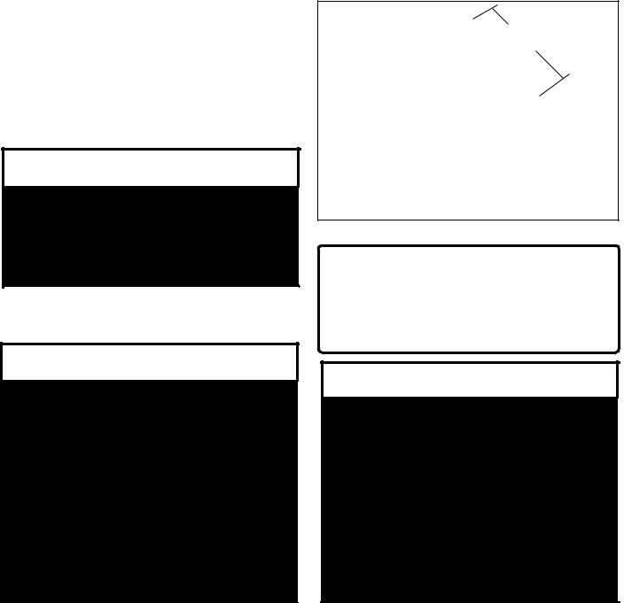
If cables or chains are used to hoist the unit they must be the same length and care should be taken to prevent damage to the cabinet / coils or condenser fans.
It is recommended the unit be hoisted with the outside air hood in the shipped position. However the unit may be hoisted with the outside air hood in an open position.
Before lifting unit, be sure that all shipping material is removed from unit. Secure hooks and cables at all lifting points / lugs provided on the unit.
▲! IMPORTANT
PRIOR TO SETTING THE UNIT ON THE CURB. To insure proper isolation and seal between the unit & curb, gasket material MUST BE APPLIED to the curb on
ALL SURFACES meeting with the unit.
▲! WARNING
Improper installation, adjustment, alteration, service or maintenance can cause property damage, personal injury or loss of life. Installation and service must be performed by a qualified installer, service agency or the gas supplier.
Install the gas fired unit to assure the flow of combustion and ventilating air is not obstructed from reaching the heater and that the flue outlet is located at least 120 inches away from any opening through which combustion products could enter the building.
INSTALLATION continued
Prior to setting the unit onto the roof curb, be sure that the gasket material has been applied to curb on all surfaces meeting with the unit.
Hoist unit to a point directly above the curb and duct openings. Carefully lower and align the unit with utility and duct openings unit perimeter fits around the curb. Make sure the unit is properly seated on the curb and is level.
Gas fired units should be installed so that the flue discharge vent is located a minimum 120" away from any opening through which combustion products might enter the building. Unit location must assure combustion and ventilation air flows are never obstructed.
Never point flue discharge in direction of fresh air intake for other equipment.
99" minimum length
LIFTING DETAIL TYPICAL FOR 2 - 30 TON UNITS
SERVICE CLEARANCES
|
LOCATION |
|
UNIT SIZE |
|
|
||
|
2 - 7 |
|
8 - 15 |
16 - 30 |
|
||
|
|
|
|
||||
|
Front - Control Door Side |
48" |
|
48" |
|
48" |
|
|
Back - Return Air End |
48" |
|
48" |
|
48" |
|
|
Left Side |
6" |
|
6" |
|
6" |
|
|
Right Side - Access Doors |
60" |
|
60" |
|
60" |
|
|
Top |
UNOBSTRUCTED |
|
||||
▲! CAUTION
Where the supply or warm air duct passes through a combustible roof, a clearance of one inch must be maintained between the outside edges of the duct and combustible material in accordance with National Fire Protection Association Standard No. 90A. Provide flashings or enclosure between structure and roof and all joints must be sealed with mastic roofing to ensure a watertight seal.
All roofing work should be performed by qualified roofing contractors.
7
INSTALLATION continued
OUTSIDE AIR HOOD
CAUTION: Prior to unit operation, the outside air hood must be opened as shown below:
APPLY
SILICONE CAULKING
ON TOP &
BOTH SIDES
OF AIR HOOD
AIR HOOD SHOWN IN THE OPEN POSITION
Remove shipping screws from each side of the hood in the "closed" postion. Lift hood to the "open" position, seal flange and secure with sheet metal screws.
Air hoods may vary according to unit size and options. The illustration shown is for practical guidelines for all outside air hoods.
Outdoor air intake adjustments should be made according building ventilation or local code requirements.
▲! WARNING
Electric shock hazard. Can cause injury or death. Before attempting to perform any service or maintenance, turn the electrical power to unit to OFF at disconnect switch(es).
Unit may have multiple power supplies.
▲! CAUTION
On three phase units the rototation must be checked on ALL MOTORS AND COMPRESSORS.
SCROLL COMPRESSORS ARE DIRECTIONAL.
Rotation must be checked on start-up by a qualified service technician using
suction and discharge gauges.
Scroll compressors will FAIL if run in the wrong direction. Blower and condenser rotation should be checked and only be altered if necessary at the power connection.
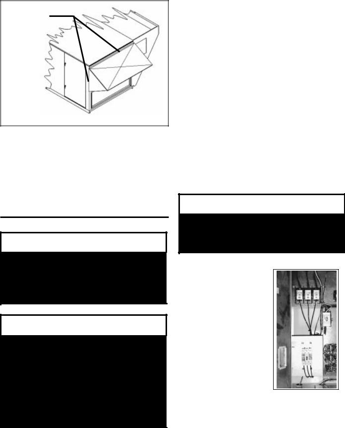
ELECTRICAL
Verify the unit data plate voltage agrees with the power supply. Route power and control wiring through the utility entry. Do not run power and signal wires in the same conduit. Connect power according to the (unit specific) wiring diagram provided.
Protect the branch circuit in accordance with code requirements. Control wires should not be run inside the same conduit. The unit must be electrically grounded in accordance with the current National Electric Code, ANSI / NFPA No. 70. In Canada use current C.S.A. Standard C22.1 Canadian Electric Code Part 1.
Power wiring is to the unit terminal block or main disconnect. All wiring beyond this point has been done by the manufacturer and cannot not be modified without effecting the unit's agency / safety certification.
AIRFLOW IS TO BE ADJUSTED AFTER INSTALLATION TO OBTAIN AN AIR TEMPERATURE RISE WITHIN THE RANGE SPECIFIED ON THE RATING PLATE.
DUE TO JOB SPECIFICATION REVISIONS, IT MAY BE NECESSARY TO ADJUST OR CHANGE THE SHEAVE OR PULLEY TO OBTAIN THE DESIRED AIRFLOW
AT THE TIME OF INSTALLATION.
▲! CAUTION
START-UP TECHNICIAN MUST CHECK BLOWER MOTOR AMPERAGE TO ENSURE THAT THE AMPERAGE LISTED ON THE MOTOR NAMEPLATE IS NOT EXCEEDED.
NOTE: All units are factory wired for 208 / 230, 460 or 575 volt. If unit is to be connected to a 208v supply, the transformer must be rewired for 208v service. For 208v service interchange the yellow and red conductor on the low voltage control transformer.
RED - BLK 208 volt ; YEL - BLK 230 volt.
8
 Loading...