


Users Information Manual
ENERGY RECOVERY UNITS
1
2
CONTENTS
IMPORTANT SAFETY INFORMATION ……… |
4 |
GENERAL INFORMATION …………………… |
5 |
Initial Mechanical Check & Setup |
|
Air Seal Adjustments |
|
Wheel-to-Air Seal Clearance |
|
AIR FLOW BALANCING & CHECKING………… 6 |
|
Controls |
|
ROUTINE MAINTENANCE & HANDLING …… |
7 |
Lifting Hole Locations Cleaning
Wheel Drive Components ……………… 7
INSTALLATION CONSIDERATIONS…………… 7
Accessibility
Orientation & Support
OPERATION ……………………………………… 8
Start Up Procedure
Diameter Seal Adjustment
Hub Seal Adjustment
SERVICE ………………………………………… 9
Segment Installation & Replacement Segment Retainer
Wheel Drive Motor & Pulley Replacement Belt Replacement ……………………… 10
DESIGN CONDITIONS & CONTROL
STRATEGIES …………………………………… 11
Standard Temperature Control
Fan Only Mode
Economizer Mode
Cooling Mode
Heating Mode
VENTILATION OF OCCUPIED SPACES
IN INDUSTRIAL APPLICATIONS ……………… 11
CROSS LEAKAGE IN ERV VENTILATION SYSTEMS ………………………………………… 12
MOISTURE TRANSFER AND FUNGAL
GROWTH IN ENTHALPY WHEELS …………… 12
SILICA GEL DESICCANT………………………… 13
ARI PERFOMANCE CERTIFICATION ………… 14
Owner should pay particular attention to the words: NOTE, CAUTION, and WARNING. NOTES are intended to clarify or make the installation easier. CAUTIONS are given to prevent equipment damage. WARNINGS are given to alert owner that personal injury and/or equipment damage may result if installation is not handled properly.
3
IMPORTANT SAFETY INFORMATION
ONLY QUALIFIED PERSONNEL SHOULD PERFORM INSTALLATION, OPERATION, AND MAINTENANCE OF EQUIPMENT DESCRIBED IN THIS MANUAL.
AAON package units are designed for safe operation when installed, operated, and maintained within design specifications, and the instructions set forth in this manual. It is necessary to follow these instructions to avoid personal injury or damage to equipment or property during equipment installation, operation, and maintenance.
WARNING
RISK OF DAMAGE, INJURY, AND LOSS OF LIFE - Improper installation, adjustment, alteration, service or maintenance can cause property damage, personal injury, or loss of life. A qualified installer or service agency must perform installation and service.
WARNING
RISK OF ELECTRICAL SHOCK -
Before attempting to perform any service or maintenance, turn the electrical power to the unit OFF at disconnect switch(es). Unit may have multiple power supplies.
 NOTE
NOTE
IMPORTANT!
This equipment is protected by a standard limited warranty under the condition that initial installation, service, and maintenance is performed according to the instructions set forth in this manual. This manual should be read in its entirety prior to installation, and before performing any service or maintenance work.
Units described in this manual are available with many optional accessories. If you have questions after reading this manual in its entirety, consult other factory documentation, or contact your sales representative to obtain further information before manipulating this equipment, or its optional accessories.
WARNING
RISK OF INJURY FROM MOVING PARTS - Disconnect all power before servicing to prevent serious injury resulting from automatic starts. Unit may have multiple power supplies.
4

GENERAL INFORMATION
The units are designed as self-contained heating, cooling or combination units using refrigerant, chilled water, natural or propane gas, electric resistance, steam or hot water as shown on the unit rating plate.
This AAONAIRE® unit has been equipped with an energy recovery heatwheel. This booklet is furnished to assure the energy recovery feature will be properly setup to perform in accordance with the job specifications for your particular application.
The AAONAIRE® heatwheel option is designed to recover energy that would normally be lost through the ventilation required by today's codes and standards for comfort and health. The benefits of energy recovery are significant in that 35 to 40 percent of the unit heating and cooling capacity can be achieved by collecting this otherwise lost energy from the exhaust air and returning this energy to the building. The cost of removing humidity in the summer is also greatly reduced by the use of the desiccant coating on the energy wheel.
The Energy Recovery Cassette consists of a frame, wheel, wheel drive system and energy transfer segments. Segments are removable for cleaning or replacement. The segments rotate through counter flowing exhaust and outdoor air supply streams where they transfer heat and/or water vapor from the warm, moist air stream to the cooler and/or drier air stream. This energy recovery process can reduce cooling design loads by up to 4 tons per 1000 CFM of outdoor air ventilation while also reducing heating demand and humidification requirements. Operating savings, reduced demand charges and first cost equipment savings provide a rapid payback to the building owner.
The initial set-up and servicing of the heatwheel is very important to maintain proper operating efficiency and building occupant comfort.
Normal maintenance requires periodic inspection of filters, the cassette wheel, drive belts, air seals, wheel drive motor and its electrical connections.
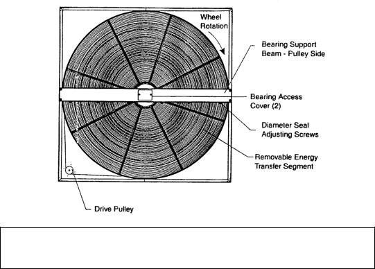
Wiring diagrams are provided with each motor. When wired according to wiring diagram, motor rotates clockwise when viewed from the shaft/pulley side.
By carefully reviewing the information within this manual and following the instructions, the risk of improper operation and/or component damage will be minimized.
It is important that periodic maintenance be performed to help assure trouble free operation. Should equipment failure occur, contact a qualified service organization with qualified, experienced HVAC technicians to properly diagnose and repair this equipment.
INITIAL MECHANICAL CHECK & SETUP
Outdoor units equipped with outside air intake will have an outside air hood. The outside air hood must be opened prior to unit operation.
Remove shipping screws from each side of the hood in the “closed” position. Lift hood to the “open” position, seal flange, and secure with sheet metal screws.
Outdoor air intake adjustments should be made according to building ventilation, or local code requirements.
After the unit installation is complete, open the cassette access door and determine that the energy wheel rotates freely when turned by hand. Apply power and observe that the wheel rotates at approximately 30 RPM. If the wheel does not rotate when power is applied, it may be necessary to readjust the "diameter air seals".
AIR SEAL ADJUSTMENTS
Pile type air seals across both sides of the energy wheel diameter are factory adjusted to provide close clearance between the air seal and wheel. Racking of the unit or cassette during installation, and / or mounting of the unit on a non level support or in other than the factory orientation can change seal clearances. Tight seals will prevent rotation.
WHEEL-TO-AIRSEAL CLEARANCE
To check wheel-to-seal clearance; first disconnect power to the unit. In some units the heatwheel assembly can be pulled out from the cabinet to view the airseals. On larger units, the heatwheel may be accessible inside the walk-in cabinet.
A business card or two pieces of paper can be used as a feeler gauge, (typically each .004" thick) by placing it between the face of the wheel and the pile seal.
Using the paper, determine if a loose slip fit exist between the pile seal and wheel when the wheel is rotated by hand.
To adjust air seal clearance, loosen all seal plate retaining screws holding the separate seal retaining
5
 Loading...