


Installation and Operation Manual
H2 / V2
Air Handlers
Horizontal / Vertical
800 – 10,000 CFM
FOR YOUR SAFETY
DO NOT STORE OR USE GASOLINE OR OTHER FLAMMABLE VAPORS AND LIQUIDS IN THE VICINITY OF THIS OR ANY OTHER APPLIANCE.
WARNING
If the information in this manual is not followed exactly, a fire or explosion may result causing property damage, personal injury, or loss of life.
Owner should pay particular attention to the words:
NOTE, CAUTION, and WARNING. NOTES are intended to clarify or make the installation easier. CAUTIONS are given to prevent equipment damage. WARNINGS are given to alert owner that personal injury and/or equipment damage may result if installation is not handled properly.
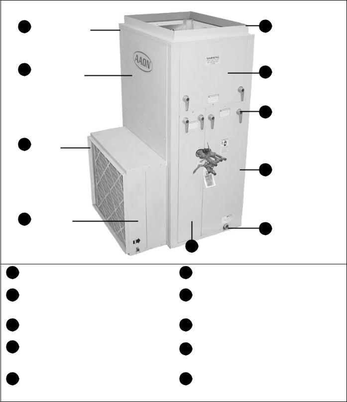
Feature Overview
1Fully Insulated 1” Double-Wall Construction
2Painted Galvanized Steel Construction
3Duct or Accessory Flange
4 |
Filter Access |
|
5 |
Coil Access |
|
10Duct or Accessory Flange
9 |
Plenum Fan Access |
|
8
Cast Half-Turn Handles
7Control Panel Access & More Coil Access
6Drain Connection on Either Side
1 |
Double-wall construction for reduced cabinet |
6 |
Stainless steel or galvanized sloped drain pan |
|
loss, better air quality, and easier cleaning. |
|
can be selected for left or right hand connection. |
2 |
Attractive pre-painted powder coat finish on a |
7 |
Remove door for access to fully enclosed |
|
cabinet that is built to last. |
|
control box and more access to coils. |
3 |
1” flange allows connection to accessory boxes, |
8 |
Half-turn cast handles pull door firmly against |
|
fiberglass or metal ductwork. |
|
automotive style gasketing for tight air seal. |
4 |
Easy slide out filter access for 2” or 4” pleated |
9 |
Full access to fan wheel, motor, and drive |
|
filters. Add a special filtration section for more |
|
components for quick servicing. |
|
air cleaning capability. |
|
|
5 |
Panel removes easily to clean or service the |
10 |
2” flange allows connection to accessory boxes, |
|
coils, and other internal components. |
|
fiberglass, or metal ductwork. |
www.aaon.com |
2 |

Contents
1.Description……………….....………... 4
Important Safety Information |
4 |
Unit Data |
5 |
Unit Orientation (Left or Right Hand) |
7 |
Model Number Nomenclature |
8 |
Base Model Number
Feature Number
2.Delivery…...……………….....………... 11
Receipt & Inspection |
11 |
Storage |
11 |
3.Installation……..………….....………... 12
General |
12 |
Certification |
12 |
Codes & Ordinances |
12 |
Handling |
12 |
Service & Installation Clearance |
12 |
Mounting & Suspension |
13 |
Sealing |
13 |
Cooling Equipment |
13 |
Heating Equipment |
14 |
Condensate Piping |
14 |
Electrical |
14 |
Thermostat |
14 |
Filters |
14 |
Tables:
5.1H2 General Data
5.2V2 General Data
6.1Water Coil Connection Sizes
6.2DX Coil Connection Sizes
18.1Bearing Setscrew Torques
20.1Bearing Lubrication Schedule
21.1Troubleshooting
4.Start-Up…...……………….....………... 15
General |
15 |
Check Out |
15 |
Procedures |
15 |
Commissioning |
16 |
5.Operation & Maintenance....………... 18
General |
18 |
Maintenance Schedule |
18 |
Blower Assembly |
18 |
Indoor Coils |
19 |
Heating |
19 |
Cleaning |
20 |
Chilled Water |
20 |
Lubrication |
20 |
Service |
20 |
Filters |
20 |
6.Troubleshooting…………….………... 21
Common Problems |
21 |
7.Factory Start-Up Form.…….………... 22
Figures:
7a Unit Orientation
8a Model Number Structure
12a Service Clearance
13a Air Handler Suspension
19a Angular Misalignment
19b Parallel Misalignment
19c Belt Deflection
3

1. Description
Important Safety Information
ONLY QUALIFIED PERSONNEL SHOULD PERFORM INSTALLATION, OPERATION, AND MAINTENANCE OF EQUIPMENT DESCRIBED IN THIS MANUAL.
H2/V2 Air Handlers are designed for safe operation when installed, operated, and maintained within design specifications and the instructions set forth in this manual. It is necessary to follow these instructions to avoid personal injury or damage to equipment or property during equipment installation, operation, start-up, and maintenance.
WARNING
RISK OF DAMAGE, INJURY, AND LOSS OF LIFE
– Improper installation, adjustment, alteration, service, or maintenance can cause property damage, personal injury, or loss of life. A qualified installer or service agency must perform installation and service.
WARNING
RISK OF ELECTRICAL SHOCK – Unit may have multiple power supplies. Turn the electrical power to the unit OFF at disconnect switch(es) before attempting to perform any service or maintenance.
WARNING
The information in this manual should be followed exactly to prevent property damage or personal injury.
WARNING
Installation and service must be performed by a qualified installer or service agency.
 NOTE
NOTE
IMPORTANT!
This equipment is protected by a standard limited warranty under the condition that initial installation, service, start-up, and maintenance is performed according to the instructions set forth in this manual. This manual should be read in its entirety prior to installation and before performing any service or maintenance work.
Equipment described in this manual is available with many optional accessories. If you have questions after reading this manual in its entirety, consult other factory documentation or contact your Sales Representative to obtain further information before manipulating this equipment or its optional accessories.
WARNING
RISK OF INJURY FROM HOT PARTS – Disconnect all power before servicing electric resistance heating elements to prevent serious injury resulting from automatic starts. Unit may have multiple power supplies.
WARNING
RISK OF INJURY FROM HOT PARTS – Disconnect all power, close all isolation valves, and allow equipment to cool before servicing equipment with hot water and steam heating coils. Hot water will circulate even after power is off. Equipment may have multiple power supplies.
WARNING
RISK OF INJURY FROM MOVING PARTS - Disconnect all power before servicing motor or
blower to prevent serious injury resulting from automatic startsWARNING. Motor and blower may have multiple power supplies.
 NOTE
NOTE
These units must not be used as a “construction heater” at any time during any phase of construction. Very low return air temperatures, harmful vapors, and misplacement of the filters will damage the unit and its efficiency.
www.aaon.com |
4 |
Unit Data
Table 5.1
|
|
|
|
|
|
|
|
|
|
|
|
H2 General Data |
|
|
|
|
|
|
|
|||||
|
|
|
|
|
|
|
|
|
|
|
|
|
|
|
|
|
|
|
|
|
|
|
|
|
|
Cabinet Size |
|
|
A |
|
B |
|
|
|
C |
|
|
C+ |
|
|
|
D |
|
||||||
|
Coil Face Area Designation |
|
|
1 |
|
1 |
|
|
1 |
|
|
2 |
|
|
3 |
|
4 |
|
1 |
|
|
2 |
|
|
|
CFM Range |
|
|
800 - 1200 |
800 - 2000 |
1800 - 3000 |
|
1800 - 4000 |
|
2000 - 4800 |
|
2500 - 6000 |
3000 - 6000 |
|
4300 - 10000 |
|
||||||||
|
Electric Heating KW |
|
|
7, 14 |
7, 14, 21 |
|
|
|
14, 21, 28, 35, 42 |
|
|
14, 28, 42, 56, 70 |
|
|||||||||||
|
Blower |
|
|
1 / 10” / FC |
|
1 / 15” / BI |
|
|
1 / 18.5” / BI |
|
|
1 / 18.5” / BI |
|
1 / 27” / BI |
|
|||||||||
|
Quantity / Wheel Dia. / Type |
|
|
|
|
|
|
|
|
|
||||||||||||||
|
|
|
|
|
|
|
|
|
|
|
|
|
|
|
|
|
|
|
|
|
|
|
||
|
|
|
|
|
|
|
|
|
|
|
|
|
|
|
|
|
|
|
|
|
|
|
|
|
|
|
Standard |
|
|
1/2* |
1 |
|
|
|
1 |
|
|
2 |
|
|
|
3 |
|
|
|||||
|
Blower Motor |
Oversize |
|
|
|
2** |
|
|
|
2 |
|
|
3 |
|
|
|
5 |
|
|
|||||
|
Maximum HP |
Double Oversize |
|
|
|
|
|
|
|
|
3 |
|
|
5 |
|
|
|
7.5 |
|
|
||||
|
|
|
|
|
|
|
|
|
|
|
|
|
|
|
|
|
|
|
|
|
|
|
|
|
|
|
Triple Oversize |
|
|
|
|
|
|
|
|
5 |
|
|
7.5 |
|
|
|
10 |
|
|
||||
|
FPT Drain Connection Size |
|
|
|
|
|
|
|
|
|
|
|
3/4” |
|
|
|
|
|
|
|
||||
|
Pleated Filter Size |
|
|
16”x20”x2 |
|
16”x20”x2 |
|
|
24”x24”x2” |
|
|
24”x24”x2” |
|
16”x20”x2” |
|
|||||||||
|
(Quantity) |
|
|
(1) |
(2) |
|
|
|
(2) |
|
|
(3) |
|
|
|
(10) |
|
|||||||
|
|
|
|
|
|
|
|
|
|
|
|
|
|
|
|
|
|
|
|
|
|
|
|
|
*Note: 1/2 HP motors are direct drive. All other motors are belt drive with adjustable motor sheave. ** 2 HP motor not available in 265/1/60.
Table 5.2
|
|
|
|
|
|
|
|
|
|
|
|
V2 General Data |
|
|
|
|
|
|
|
|||||
|
|
|
|
|
|
|
|
|
|
|
|
|
|
|
|
|
|
|
|
|
|
|
|
|
|
Cabinet Size |
|
|
A |
|
B |
|
|
|
C |
|
|
C+ |
|
|
|
D |
|
||||||
|
Coil Face Area Designation |
|
|
1 |
|
1 |
|
|
1 |
|
|
2 |
|
|
3 |
|
4 |
|
1 |
|
|
2 |
|
|
|
CFM Range |
|
|
800 - 1200 |
800 - 2000 |
1800 - 3000 |
|
1800 - 4000 |
|
2000 - 4800 |
|
2500 - 6000 |
|
3000 – 6000 |
|
4300 - 10000 |
|
|||||||
|
Electric Heating KW |
|
|
7, 14 |
7, 14, 21 |
|
|
|
14, 21, 28, 35, 42 |
|
|
14, 28, 42, 56, 70 |
|
|||||||||||
|
Blower |
|
|
1 / 10” / FC |
|
1 / 15” / BI |
|
|
1 / 18.5” / BI |
|
|
1 / 18.5” / BI |
|
1 / 27” / BI |
|
|||||||||
|
Quantity / Wheel Dia. / Type |
|
|
|
|
|
|
|
|
|
||||||||||||||
|
|
|
|
|
|
|
|
|
|
|
|
|
|
|
|
|
|
|
|
|
|
|
||
|
|
|
|
|
|
|
|
|
|
|
|
|
|
|
|
|
|
|
|
|
|
|
|
|
|
|
Standard |
|
|
1/2* |
1 |
|
|
|
1 |
|
|
2 |
|
|
|
3 |
|
|
|||||
|
Blower Motor |
Oversize |
|
|
|
2** |
|
|
|
2 |
|
|
3 |
|
|
|
5 |
|
|
|||||
|
Maximum HP |
Double Oversize |
|
|
|
|
|
|
|
|
3 |
|
|
5 |
|
|
|
7.5 |
|
|
||||
|
|
|
|
|
|
|
|
|
|
|
|
|
|
|
|
|
|
|
|
|
|
|
|
|
|
|
Triple Oversize |
|
|
|
|
|
|
|
|
5 |
|
|
7.5 |
|
|
|
10 |
|
|
||||
|
FPT Drain Connection Size |
|
|
|
|
|
|
|
|
|
|
|
3/4” |
|
|
|
|
|
|
|
||||
|
Pleated Filter Size |
|
|
16”x20”x2 |
|
24”x24”x2” |
|
|
16”x 20”x2” |
|
|
16”x20”x2” |
|
16”x20”x2” |
|
|||||||||
|
(Quantity) |
|
|
(1) |
(1) |
|
|
|
(4) |
|
|
(6) |
|
|
|
(9) |
|
|
||||||
|
|
|
|
|
|
|
|
|
|
|
|
|
|
|
|
|
|
|
|
|
|
|
|
|
*Note: 1/2 HP motors are direct drive. All other motors are belt drive with adjustable motor sheave. ** 2 HP motor not available in 265/1/60.
5

Table 6.1
|
Water Coil Connection Sizes |
|
|
|
|
|
|
|
|
|
|
|
|
|
|
|||||||||
|
GPM |
|
|
Sweat Conn. |
|
MPT Conn. |
|
|
|
|
|
|
|
|
|
|
|
|
|
|||||
|
|
|
Size (In.) |
|
Size (In.) |
|
|
|
|
|
|
|
|
|
|
|
|
|
|
|||||
|
|
|
|
|
|
|
|
|
|
|
|
|
|
|
|
|
|
|
|
|||||
|
1.5 – 2.5 |
|
5/8 |
|
1/2 |
|
|
|
|
|
|
|
|
|
|
|
|
|
|
|
||||
|
|
|
|
|
|
|
|
|
|
|
|
|
|
|
|
|||||||||
2.6 |
– 7 |
7/8 |
|
1/2 |
|
|
|
|
|
|
|
|
|
|
|
|
|
|
|
|||||
|
7.1 – 14 |
|
1 |
1/8 |
|
1 |
|
|
|
|
|
|
|
|
|
|
|
|
|
|
|
|||
|
14.1 |
– 24 |
|
1 |
3/8 |
|
1 1/4 |
|
|
|
|
|
|
|
|
|
|
|
|
|
|
|
||
24.1 |
– 40 |
1 |
5/8 |
|
1 1/2 |
|
|
|
|
|
|
|
|
|
|
|
|
|
|
|
||||
|
40.1 |
– 80 |
|
2 |
1/8 |
|
2 |
|
|
|
|
|
|
|
|
|
|
|
|
|
|
|
||
|
|
|
|
|
|
|
|
|
|
|
|
|
|
|
|
|||||||||
|
80.1 – 150 |
|
2 |
5/8 |
|
2 1/2 |
|
|
|
|
|
|
|
|
|
|
|
|
|
|
|
|||
|
|
|
|
|
|
|
|
|
|
|
|
|
|
|
|
|||||||||
150.1 |
– 250 |
3 |
1/8 |
|
3 |
|
|
|
|
|
|
|
|
|
|
|
|
|
|
|
||||
|
Table 6.2 |
|
|
|
|
|
|
|
|
|
|
|
|
|
|
|
|
|
|
|
|
|
||
|
|
|
|
|
|
|
|
|
|
|
|
|
|
|
|
|
|
|
|
|
|
|||
|
|
|
|
|
|
|
|
|
DX Coil Stub Out Connection Sizes |
|
|
|
|
|
|
|||||||||
|
|
Cabinet Size |
|
|
|
A |
|
B |
|
C |
|
C+ |
|
|
D |
|
||||||||
|
|
|
|
|
|
|
|
|
|
|
|
|
|
|
|
|
|
|
|
|
|
|
|
|
|
Coil Face Area Designation |
|
|
1 |
|
1 |
1 |
|
|
2 |
3 |
|
4 |
1 |
|
|
2 |
|
||||||
|
|
|
|
|
|
|
|
|
|
|
|
|
|
|
|
|
|
|
|
|
|
|
|
|
|
|
Coil Selection |
|
|
|
|
|
|
|
|
|
|
|
|
|
|||||||||
|
|
|
|
|
|
|
|
|
Stub Out Size (Suction - Liquid) |
|
|
|
|
|
||||||||||
|
|
|
|
|
|
|
|
|
|
|
|
|
|
|
|
|
|
|
|
|
|
|
|
|
|
Single Circuit |
|
|
Standard |
|
|
7/8” – 1/2 ” |
|
7/8” – 1/2 ” |
1 1/8” – 5/8” |
|
|
1 1/8” – 5/8” |
|
|
1 3/8” – 5/8” |
|
|
|
|
||||
|
|
|
Oversized |
|
|
|
|
|
|
|
|
|
1 1/8” – 5/8” |
|
|
1 1/8” – 5/8” |
|
|
|
|
|
|||
|
|
|
|
|
|
|
|
|
|
|
|
|
|
|
|
|
|
|
|
|
||||
|
Double Circuit |
|
|
Standard |
|
|
|
|
7/8” – 1/2 ” |
1 1/8” – 5/8” |
|
|
1 1/8” – 5/8” |
|
|
1 3/8” – 5/8” |
|
|
|
|
||||
|
|
|
Oversized |
|
|
|
|
|
|
|
|
|
1 1/8” – 5/8” |
|
|
1 1/8” – 5/8” |
|
|
|
1 3/8” – 5/8” |
||||
|
|
|
|
|
|
|
|
|
|
|
|
|
|
|
|
|
|
|
||||||
www.aaon.com |
6 |

Unit Orientation
Determine left hand or right hand piping connections:
Figure 7a, Unit Orientation
Horizontal Air Handler
Left Hand Side
Top View
Return Air |
AIRFLOW |
|
Supply Air
Connections & service |
Right Hand Side |
access on right side for |
|
right hand orientation |
|
Remember: Consider the air to be “hitting the back of your head” as you face the return air inlet.
Vertical Air Handler |
|
Top View |
|
|
|
|
|
|
Left Hand Side
Supply Air
Return Air
Right Hand Side
Connections and service access on right side for right hand orientation
AIRFLOW
7
Model Number Nomenclature
The base model number identifies main unit features. The feature number identifies optional features ordered with the equipment. Together, they comprise the complete model number.
Figure 8a, Model Number Structure
Base Model Number |
|
Feature Number |
||
|
|
|
|
|
|
|
|
|
|
H2 – C1 – 2 – 10 – 3B1 : A 0 0 0 D 0 A 0 0 0
Complete Model Number
www.aaon.com |
8 |

Base Model Number
MAIN FEATURES
TYPE |
|
CABINET |
VOLTAGE |
COOLING |
|
HEATING |
|||||||||
|
SIZE |
|
|||||||||||||
|
2 |
- |
- |
|
|
- |
|
|
|
- |
|
|
|
||
|
|
|
|
|
|
|
|
|
|
|
|||||
|
|
|
|
|
|
|
|
|
|
|
|
|
|
|
|
TYPE
H = Horizontal
V = Vertical
CABINET SIZE
Coil Face Area
A1 = Standard Only
B1 = Standard Only
C1 = Standard
2 = Oversize
C+ 3 |
= Double Oversize |
4 |
= Triple Oversize |
D1 = Standard
2 = Oversize
|
VOLTAGE |
|
|
1 = |
208-230V/1Ø/60HZ |
|
|
2 = |
208-230V/3Ø/60HZ |
|
|
3 = |
460V/3Ø/60HZ |
|
|
4 = |
575V/3Ø/60HZ |
|
|
5 = |
115V/1Ø/60HZ |
|
|
6 = |
380-415V/3Ø/50HZ |
|
|
7 = |
265V/1Ø/60HZ |
|
|
8 = |
115V/1Ø/60HZ |
|
|
|
|
|
|
COOLING |
|
||
00 = No Cooling |
HEATING |
||
10 = Evaporator / Single Circuit |
|
|
|
|
|
|
|
|
|
|
16 = Evaporator / Single Circuit – Six Row |
000 = |
|
No Heating |
|||||||
50 = Evaporator / Double Circuit |
100 = |
|
Steam Coil |
|||||||
56 = Evaporator / Double Circuit – Six Row |
200 = |
|
Hot Water Coil |
|||||||
20 = Chilled Water / Standard Coil |
3 |
|
|
|
|
|
|
= |
Electric Heat |
|
30 = Chilled Water / Optional Coil |
|
|
|
|
|
|
|
|
|
|
40 = Chilled Water / Optional Coil – Six Row |
|
|
|
|
|
|
|
|||
99 = Special Coil Selection |
|
|
|
|
|
|
|
|
|
|
|
|
|
|
|
|
|
|
|
|
|
kW* |
|
|
|
STAGING |
||||||
A = |
7 (5.3) |
|
|
|
|
|
|
|
1 = |
1 Stage |
B = |
14 (10.5) |
|
|
|
|
|||||
|
|
|
|
2 = |
2 Stage |
|||||
C = |
21 (15.8) |
|
|
|
|
|||||
|
|
|
|
3 = |
3 Stage |
|||||
D = |
28 (21.0) |
|
|
|
|
|||||
|
|
|
|
4 = |
4 Stage |
|||||
H = |
35 (26.3) |
|
|
|
|
|||||
|
|
|
|
|
|
|||||
E = |
42 (31.5) |
|
|
|
|
|
|
|||
F = |
56 (42.0) |
|
|
*kW in parentheses is 208V |
||||||
G = |
70 (52.5) |
|
|
|||||||
|
|
|
|
|
|
|||||
9
 Loading...