


HB-005
B
H
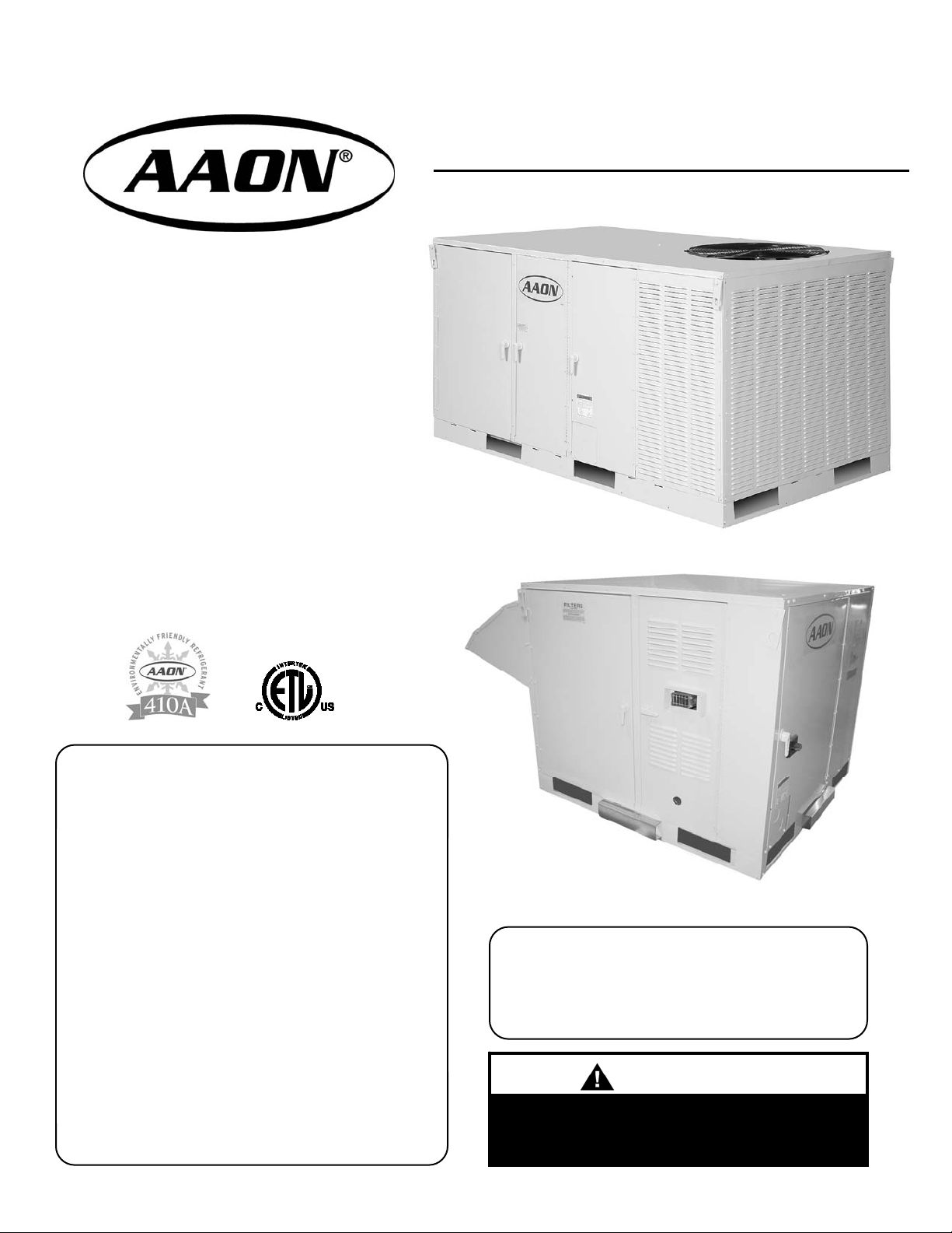
Package Units
& Air Handlers
• R-410A DX or Chilled Water Cooling
• Gas, Electric or Hot Water Heat
• Bottom or Side Discharge
FOR YOUR SAFETY
WHAT TO DO IF YOU SMELL GAS
• EXTINGUISH ANY OPEN FLAME
• DO NOT TOUCH ANY ELECTRICAL SWITCH
• DO NOT TRY TO LIGHT ANY APPLIANCE
• DO NOT USE ANY PHONE IN YOUR BUILDING
• IMMEDIATELY CALL YOUR GAS SUPPLIER
FROM A NEIGHBOR’S PHONE. FOLLOW THE
GAS SUPPLIER’S INSTRUCTIONS.
• IF YOU CANNOT REACH YOUR GAS
SUPPLIER, CALL THE FIRE DEPARTMENT.
Series
Installation and User Manual
R-410A Package
Air Handler
FOR YOUR SAFETY
DO NOT STORE OR USE GASOLINE OR OTHER
FLAMMABLE VAPORS AND LIQUIDS IN THE
VICINITY OF THIS OR ANY OTHER APPLIANCE.
WARNING
If the information in this manual is not followed
exactly, a fire or explosion may result causing
property damage, personal injury, or loss of life.

Owner should pay particular attention to the words: NOTE, CAUTION, and WARNING. NOTES are
intended to clarify or make the installation easier. CAUTIONS are given to prevent equipment damage.
Contents
WARNINGS are given to alert owner that personal injury and/or equipment damage may result if installation
is not handled properly.
1. Description ………………………………... 3
Important Safety Information
Package Unit Orientation
Air Handling Unit Orientation
2. Model Number Description ....………….. 6
Unit Model Number
3. User’s Information ……….....…………… 7
DX Cooling Units (and Remote Cond. Units)
Hydronic Cooling & Heating
Gas or Electric Heating
Filter Sizes
Multiple Unit Operation
Wiring Diagrams
Condensate Piping
Normal Thermostat Operation
Night and Vacancy Operation
Gas Heating System
Hot Gas Reheat & Hot Gas Bypass System
Filter Sizes
Cabinet Construction
4. Delivery ……………………………………. 10
Receipt & Inspection
Storage
5. Installation ………………………………… 10
General
Codes & Ordinances
Handling
Heating and Cooling Systems
Service & Installation Clearances
Setting the Unit
Electrical
Standard Control Board
Optional Control Board
Optional Control Board
Table Index: Figure Index
4.1
5.1
9.1
16.1
16.2
16.3
21.1
21.2
27.1
Package Unit Dimensions
AHU Dimensions
Filter Sizes
Blink Codes: Standard Board
Blink Codes: Optional Board
Low Voltage Wiring Sizes
Minimum Gas Piping Sizes
Gas Piping Support Intervals
Filter Sizes
4a
5a
7a
8a
9a
9b
12a
12b
12c
Thermostat
6. Start-Up …………………………….. 23
7. Operation & Maintenance ……….. 26
8. Hot Gas Bypass (External) …..….. 28
9. Hot Gas Reheat (Modulating) …... 28
10. Pressure-Temperature Chart …… 31
Economizer Option
Return Air Bypass Option
Modulating Hot Gas Reheat
Gas Piping
Condensate Piping
General
Procedures
Air Balancing
Water Balancing
Controls
General
Maintenance Schedule
Cooling
Condenser Fan
Blower Assembly
Heating Sequence
Chilled Water
Filters
Cleaning
Service
Pkg. Unit Orientation
AHU Orientation
Piping Chase Location
Heat Exchangers
MHGRH+HGBP System
Foam Panel (HPCP)
Service Clearances
Airflow Clearances
Other Clearances
2
13a
14a
15a
18a
20a
22a
26a
27a
28a
Removing Shipping Brackets
Lifting Lugs and Outside Air Hood
Power and Control Wiring
External Control Inputs to Control Board
Reheated Supply Air Temperature
Gas Piping
Blower Section
Filter Section
Hot Gas Reheat System
1. Description
Important Safety Information
ONLY QUALIFIED PERSONNEL SHOULD
PERFORM INSTALLATION, OPERATION, AND
MAINTENANCE OF EQUIPMENT DESCRIBED IN
THIS MANUAL.
HB series package units are designed for safe
operation when installed, operated, and maintained
within design specifications, and the instructions set
forth in this manual. It is necessary to follow these
instructions to avoid personal injury or damage to
equipment or property during equipment installation,
operation, and maintenance.
This equipment is protected by a standard limited
warranty under the condition that initial installation,
service, and maintenance is performed according
to the instructions set forth in this manual. This
manual should be read in its entirety prior to
installation, and before performing any service or
maintenance work.
Units described in this manual are available with
many optional accessories. If you have questions
after reading this manual in its entirety, consult
other factory documentation, or contact your sales
representative to obtain further information before
manipulating this equipment, or its optional
accessories.
IMPORTANT!
WARNING
RISK OF DAMAGE, INJURY, AND LOSS OF LIFE
- Improper installation, adjustment, alteration,
service or maintenance can cause property
damage, personal injury, or loss of life. A qualified
installer or service agency must perform
installation and service.
NOTE
RISK OF ELECTRICAL SHOCK Before attempting to perform any service or
maintenance, turn the electrical power to the unit
OFF at disconnect switch(es). Unit may have
multiple power supplies.
WARNING
RISK OF INJURY FROM MOVING PARTS Disconnect all power before servicing to prevent
serious injury resulting from automatic starts. Unit
may have multiple power supplies.
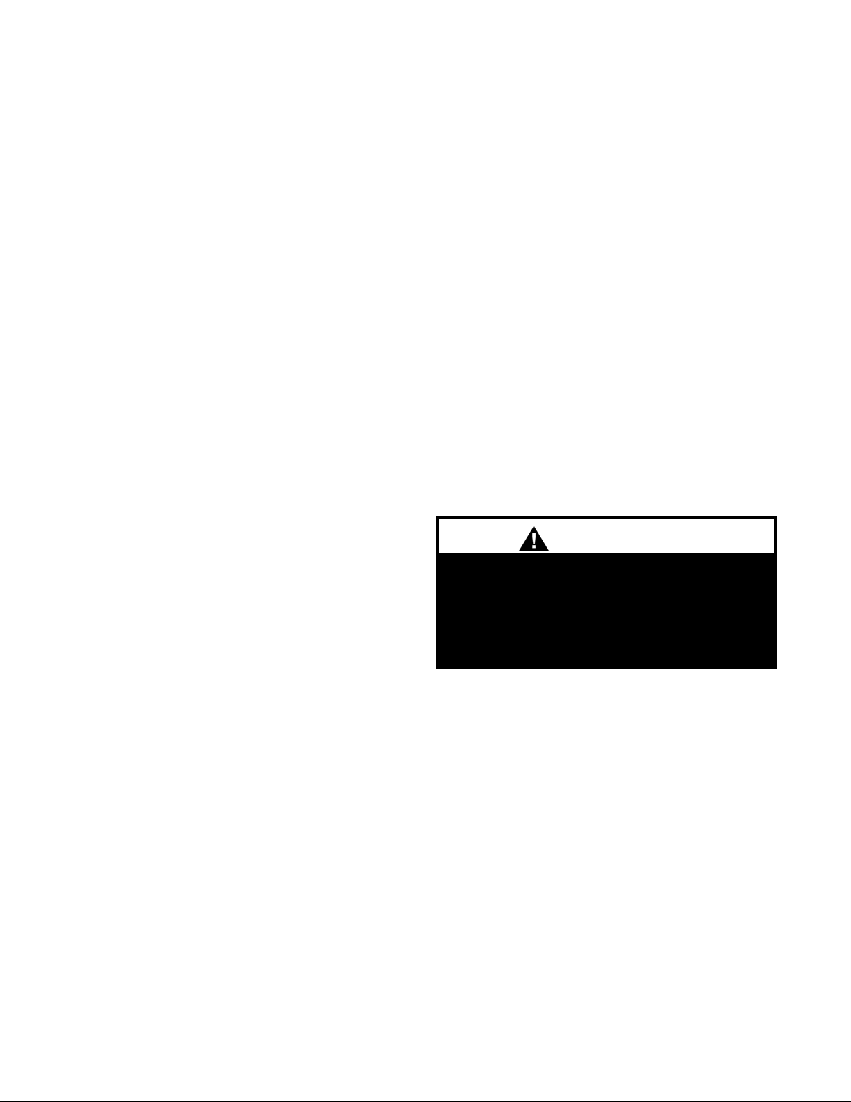
WARNING
WARNING
ON 3 PHASE UNITS ONLY - Scroll compressors
will be damaged by operation with the wrong
rotation. THE LOW PRESSURE SWITCH HAS
BEEN DISCONNECTED AFTER TESTING AT
THE FACTORY. The wiring must be reconnected
and proper rotation determined at the time of startup by a qualified service technician using suction
and discharge pressure gauges. Any alteration
should only be made at the unit power connection.
This equipment uses R-410A only, and operates at
higher pressures than standard R-22 systems. Do
not use R-22 service equipment or tools on R410A systems. Improper use or service may result
in injuries from parts under high pressure.
WARNING
The Clean Air Act of 1990 bans the intentional
venting of refrigerant (CFC’s and HCFC’s) as of
July 1, 1992. Approved methods of recovery,
recycling or reclaiming must be followed. Fines
and/or incarceration may be levied for noncompliance.
WARNING
3
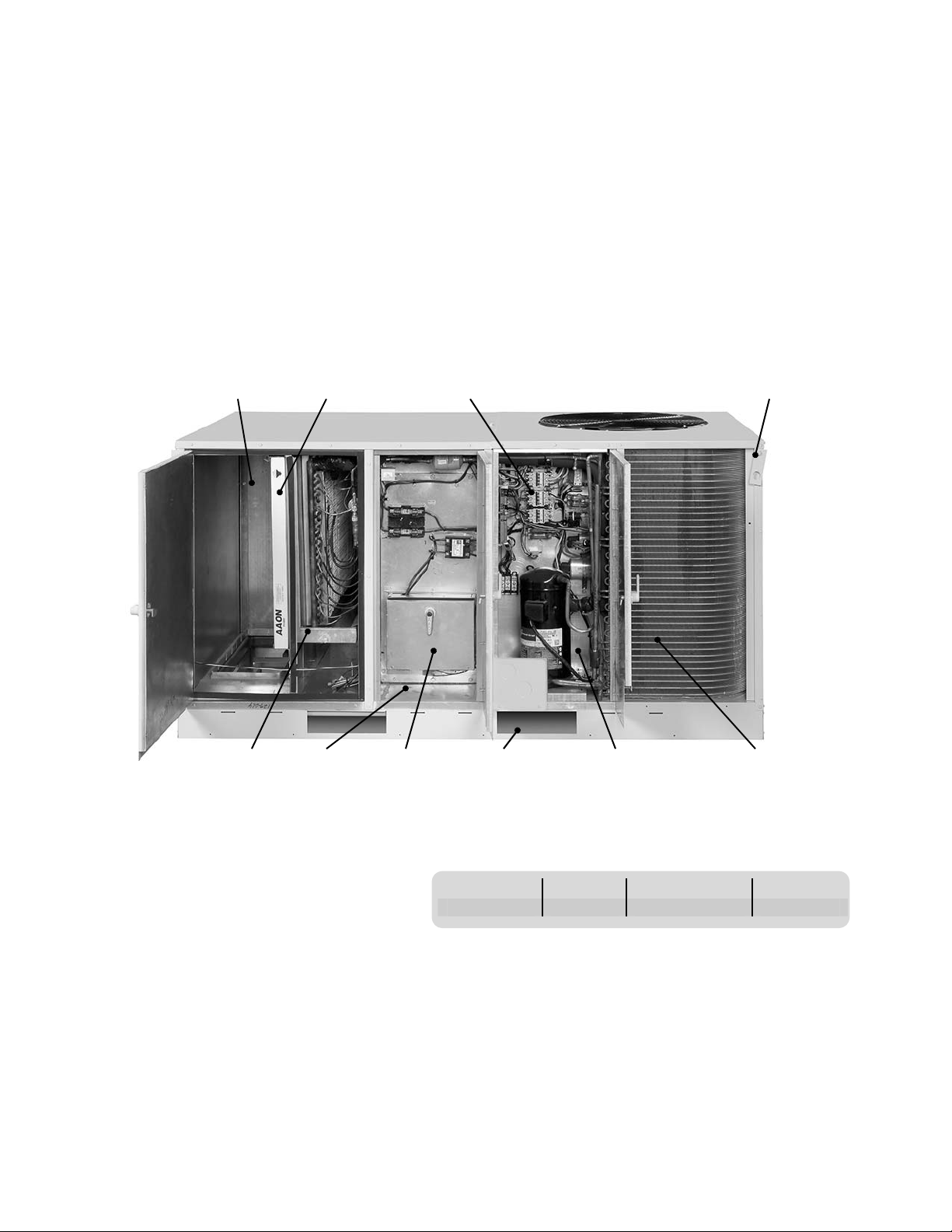
Package Unit Orientation (Compressorized)
Service access is from the front of the unit.
As you face the front of the unit, the condensing section will be on
the right end of the unit, and the air handling section on the left.
The drain connection is located on the back.
Figure 4a, Package Unit Orientation
Return /
Outside Air /
Economizer
Section
Filter
Section
Controls
Section
Evaporator
Section
Supply Air
Section
Heating
Section
Forklift
Openings
Table 4.1, Package Unit Dimensions
Model Width Length Height
002 - 005 42.25” 74.25” (93.25”)* 38”
*If present, the outside air hood will increase the overall
installed unit length by 19” for a total length of 93.25”.
Compressor
Compartment
Top Lifting Lugs
on Each Corner
Condenser
Section
4
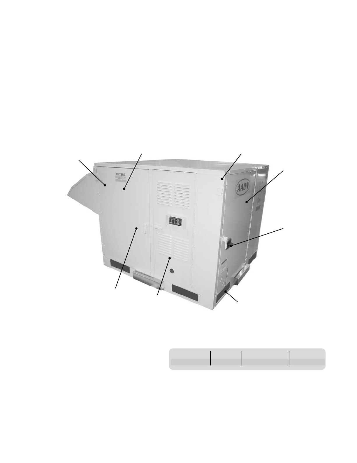
Air Handling Unit Orientation (Non-Compressorized)
Service access is from the front of the unit.
As you face the front of the unit, the controls section will be on the
right end of the unit, and the air handling section on the left.
The drain connection is located on the back.
Figure 5a, Air Handler (Non-Compressorized) Unit Orientation
Return /
Outside Air /
Economizer
Section
Filter
Section
Coil Section
Heating
Section
Table 5.1, AHU Dimensions
Model Width Length Height
002 - 005 42.25” 44.75” (63.75”)* 38”
*If present, the outside air hood will increase the overall
installed unit length by 19” for a total length of 63.75”.
Top Lifting Lugs
on Each Corner
Controls
Section
Power Disconnect
Switch
Forklift
Openings
5
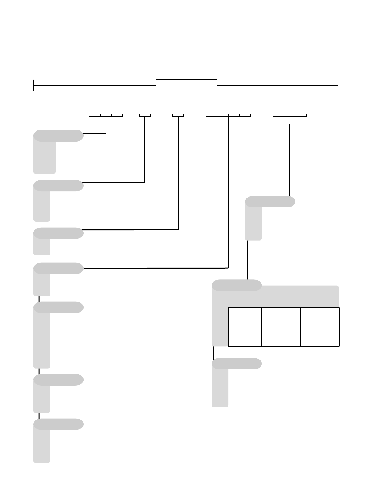
2. Model Number Description
Unit Model Number
002 =
003 =
004 =
005 =
3 =
A =
B =
V =
H =
A1
0 =
A =
B =
A2
0 =
2 =
3 =
A =
Q =
U =
W =
Y =
Z =
A3
0 =
1 =
8 =
9 =
A4
Nom. Tons Model
HB
Nominal Tons
2 Tons
3 Tons
4 Tons
5 Tons
Voltage
460V/3∅/60HZ
208-230V/1∅/60HZ
208-230V/3∅/60HZ
- -
Discharge
Vertical
Horizontal
Style
No Refrigerant
R-410A
R-410A w/ 2 Step Compressor
Configuration
No Cooling
Non-comp. w/ Std. DX Coil
Non-comp. w/ Std. DX Coil w/ RA Bypass
Air Cooled Cond. w/ Std. DX Coil
Air Cooled Cond. w/ Std. DX Coil w/ RA Bypass
Chilled Water 4 Row Coil
Chilled Water 4 Row Coil w/ RA Bypass
Chilled Water 3 Row Coil w/ 1 Row Preheat
Chilled Water 3 Row Coil w/ RA Bypass & 1 Row Preheat
Coating
No Coating
Phenolic Coated Coils - Evap. & Cond.
Phenolic Coated Condenser Coil Only
Phenolic Coated Evaporator Coil Only
Staging
No Cooling
0 =
Single Stage
1 =
Dual Stage (w/ 2 step compressor)
2 =
Single Serpentine Chilled Water
M =
Half Serpentine Chilled Water
N =
Voltage
Main Features
Discharge
Location
- - -
A1 A2 A3 A4
Cooling
Heating
B1 B2 B3
B1
Type*
0 =
No Heat
1 =
Electric Heat
2 =
Natural Gas Aluminized
E =
Hot Water
F =
Hot Water w/ Phenolic Coating
Note: LP gas and high altitude
conversion kits are available
for field installation.
B2
Designation
Gas Capacity Electric Capacity
Mbtu kW 208V kW 240-480V
0 =
1 =
2 =
3 =
4 =
5 =
No Heat
45
60
75
100
125
-
7.5
15
22.5
-
-
B3
Staging
No Heat
0 =
1 Stage (Gas or Electric)
1 =
2 Stage (Gas or Electric)
2 =
3 Stage (Electric Only)
3 =
Single Serpentine (Hot Water)
M =
Half Serpentine (Hot Water)
N =
6
10
20
30
-
-

3. User’s Information
Failure to observe the following instructions may
result in premature failure of your system, and
possible voiding of the warranty.
WARNING
DX (Direct Expansion) Package Units and DX
Units with Remote Condenser
Never cut off the main power supply to the unit, except
for complete shutdown.
Always control the system from the thermostat, or
control panel, and never at the main power supply
(except in an emergency, or complete shutdown of the
system).
During the cooling season, if the airflow is reduced due
to dirty air filters, or other reasons, the cooling coils will
get too cold and result in excessive liquid return to the
compressor. As the liquid concentration accumulates,
oil is washed out of the compressor leaving it starved
for lubrication.
The compressors must be on a minimum of four
minutes, and off for a minimum of five minutes. The
cycle rate must not exceed eight starts per hour.
THE COMPRESSOR LIFE WILL BE SERIOUSLY
SHORTENED BY RESULTING REDUCED
LUBRICATION, AND THE PUMPING OF EXCESS
AMOUNTS OF LIQUID OIL AND REFRIGERANT.
Hydronic Cooling and Heating
Non-compressorized units may contain chilled water
and/or hot water coils. Units are provided with internal
header connections for field piping. Vent and drain
connections can be accessed within the unit.
Piping is to be run via the 4” x 7” piping chase located
in the cabinet floor inside the coil compartment,
accessible through the coil compartment access door
on the front of the unit. Piping to coil header
connections must be supported independently of the
coil to prevent undue stress from weakening
connections over time. Allow adequate flexibility for
thermal expansion of the piping.
Use proper glycol solutions or brines to help prevent
coil freezing. Consult the designer or project engineer
if you have concerns about lower than normal entering
air temperatures (typically air temperatures below
40°F) that could cause coils to freeze.
Figure 7a, Piping Chase Location
Utility Entry
4” x 2 1/2”
Shipping
Bracket
Piping Chase
4” x 7”
Front
Return Supply
Back
Gas or Electric Heating
The system is designed to heat a given amount of air
each minute of operation. If the amount of air heated
is greatly reduced (approximately 1/3 capacity), the
heat exchanger (or heater coil if electric) temperature
will increase above acceptable levels, and will result in
shut down by a high temperature safety switch
incorporated into either the heat exchanger, or the
heater area.
GAS HEAT UNITS – If heat shuts off due to safety
switch, or gas supply shut off failure, then always
close manual gas valve to unit prior to any
electrical service. Prolonged overheating of the
heat exchanger will shorten its life.
Improper installation, adjustment, alteration,
service, or maintenance can cause property
damage, personal injury, or loss of life. Installation
and service must be performed by a qualified
installer, service agency, or if gas fired units, the
gas supplier. Refer to installation instructions
provided with the unit, and this manual.
WARNING
WARNING
7
Multiple Unit Operation
When several units are used in conditioning the space,
and any are combination heating-cooling units, all
system thermostat switches must be set at either
heating, cooling, or set at ‘OFF’. Do not run part of a
system switched to an opposite mode. Cooling only
units should be switched to ‘OFF’ at the thermostat
during the heating season.
Wiring Diagrams
A complete set of unit specific wiring diagrams in both
ladder and point-to-point form are laminated in plastic
and affixed to the inside of the service access door.
Condensate Piping
A drain trap must be connected to the drain connection
located on the back of the unit. If codes require a
condensate drain line, it should be the same pipe size
as the drain nipple and should pitch downward for its
entire length toward the drain.
A “P” Trap is factory supplied and shipped in the
control access compartment for field installation. An
air break should be used with long runs of cond ensate
lines.
Normal Thermostat Operation
For Heating
- Set system switch to ‘HEAT’
- Set fan switch to ‘AUTO’ or ‘ON’
- Set the desired temperature
For Cooling
- Set system switch to ‘COOL’
- Set fan switch to ‘AUTO’ or ‘ON’
Air Circulation
Set the system switch to ‘OFF’
-
Set the fan switch to ‘ON’
System Off
-
Set the system switch to ‘OFF’
Set the fan switch to ‘AUTO’
-
-
Do not change temperature setting
With these settings the system is shut down,
-
except for the 24-volt control system power, and
the compressor crankcase heater (approx. 60W).
Night and Vacancy Operation
To reduce the operation time during low load periods,
it is recommended that the temperature setting be
increased by 5°F during non-occupied periods of the
cooling season in commercial buildings, such as nights
and weekends. Decrease the temperature by 10°F at
these times during the heating season.
Gas Heating System
The heating section is for use with natural gas supply
pressure of 6” to 10.5” w.g. The unit may also utilize
propane gas (after installation of a field conversion kit)
with a supply pressure to the valve of 11” to 12” w.g.
The rating plate on the furnace must be inspected to
make sure the unit is stamped for proper gas. A 1/8”
pressure tap should be field supplied by the installer in
the piping just ahead of the gas valve. The pressure
tap on the outlet end of the gas valve can be checked
to verify manifold pressure of 3.2” to 3.5” w.g. for
natural gas or 11” to 12” w.g. for propane.
A centrifugal blower that draws in outside air through a
protected opening supplies combustion air.
This induced draft blower introduces the air to the
blower tubes, which assures even primary and
secondary airflow.
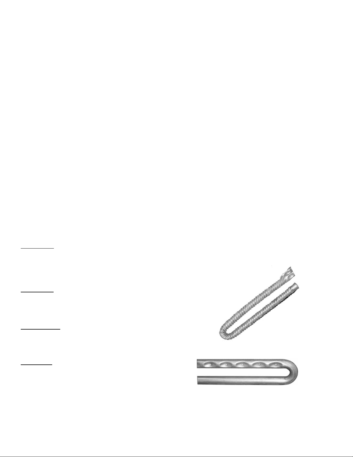
Gas heating units use AAON’s patented high efficiency
twisted tube, or dimpled heat exchanger. All heating
system and related safety controls are 100% tested on
each unit prior to shipment.
Figure 8a, HB Gas Heat Exchangers
Dimpled Tube
Twisted Tube
8
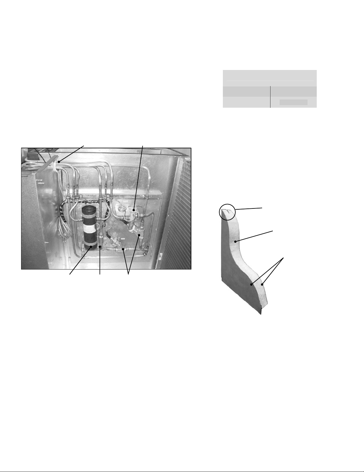
Modulating Hot Gas Reheat and Hot Gas
Bypass Systems on DX Units
Some DX cooling units may contain Modulating Hot
Gas Reheat (MHGRH) and/or Hot Gas Bypass
(HGBP) systems as factory installed options. Piping
and valves for these systems will be located on the
inside wall of the condenser section. The condenser
top must be removed for access to these components.
Figure 9a, MHGRH and HGBP System
Piping to
Compressor and
Coil Compartments
HGBP
Valve
Receiver
Tank
Check
Valve
MHGRH
Valves
Filter Sizes
Table 9.1, Pleated Filter Sizes
All 2-5 Ton HB Packaged Units
Qty. Size
2 20” x 25” x 2”
Cabinet Construction
All HB units are insulated with closed-cell polyurethane
foam, which has twice the R-value of fiberglass
insulation. All cabinet walls and roof use double-wall
G90 galvanized steel. The solid core foam interior
provides a rigid, impact resistant surface. All panels
have a thermal break with no metal-to-metal contact
from outside to inside.
Figure 9b, High Performance Composite Panel
Thermal Break
Foam Core
Double-Wall
9
4. Delivery
ALL SHIPMENTS ARE F.O.B. THE FACTORY. IT IS
THE RESPONSIBILITY OF THE RECEIVING PARTY
TO INSPECT THE EQUIPMENT UPON ARRIVAL.
Receipt & Inspection
The unit should be inspected for damage that may
have occurred in transit. Do the following upon
receipt:
1. Inspect all items for internal, external, and
concealed damage before accepting
2. Assure carrier is in compliance with Bill of
Lading instructions
If damage is found:
1. Note all damage on Bill of Lading immediately
− Photograph damage if possible
− Do not move or discard damaged
packaging materials
2. Call carrier immediately to file a freight claim,
and to schedule a freight inspection
3. When damage is repairable, contact the
factory for replacement parts: 918-583-2266
4. With permission of carrier, make the repairs
5. Stay in contact with carrier to ensure payment
of your claim
If repairs must be made to damaged goods, the factory
must be notified before any repair action is taken.
Equipment alteration, repair, or unauthorized
manipulation of damaged equipment without the
manufacturer’s consent will void all product warranties.
Contact the AAON Warranty Department for
assistance with handling damaged goods, repairs, and
freight claims: 918-583-2266.
Verify the equipment against the order documents
upon delivery. If what you received does not match
your order exactly, then notify your Sales
Representative at once.
Storage
This equipment is designed for outdoor use. However,
if installation will not occur immediately following
delivery, then store equipment in a protected area, and
in the proper orientation as marked on the packaging
with all internal packaging in place. Secure all looseshipped items.
5. Installation
General
DX models of this unit use R-410A refrigerant only,
and should not be used with any other refrigerant. HB
package units are for outdoor installation only.
Codes & Ordinances
System should be sized in accordance with National
Warm Air Heating and Air Conditioning Association
Literature, or the Guide of American Society of
Heating, Refrigeration and Air Conditioning Engineers.
The installation must conform with local building
codes, or in the absence of local codes, with (United
States) National Fuel Gas Code “ANSI-Z223.1”,
(Canada) current CAN/CGA-B149.1 or B149.2.
Installation codes for Gas Burning Appliances and
Equipment, current C.S.A. Standard C22.1, Canadian
Electrical Code Part 1, and C.S.A. Standard B52
Mechanical Refrigeration Code, and Local Plumbing or
Waste Water Codes.
It is the responsibility of the installing contractor to
comply with codes, ordinances, local and
municipal building laws, and manufacturer’s
instructions. Personal injury and/or equipment
damage may result if proper procedures are not
followed.
Handling
Be aware of what is contained in the equipment!
Dependent upon the optional accessories that were
ordered, this equipment may contain fragile
components and delicate electronics. Although the
unit is constructed of sturdy materials, avoid impacts
and handling methods that may damage internal
apparatus and structure, or the exterior painted
surfaces of the unit. Take care not to apply destructive
force to coils, or other parts protruding beyond the
extents of the unit casing. Always handle the unit by
its exterior casing.
Keep equipment free from debris, and construction
waste during installation. Foreign materials may
adversely affect unit operation resulting in premature
failures that will not be covered by the manufacturer’s
WARNING
10
 Loading...