


LL-540
Table of contents
 Loading...
LL Series
Chillers and Outdoor Mechanical Rooms
FIRE OR EXPLOSION HAZARD
Failure to follow safety warnings
exactly could result in serious injury,
death or property damage.
Be sure to read and understand the
installation, operation and service
instructions in this manual.
Improper installation, adjustment,
alteration, service or maintenance
can cause serious injury, death or
property damage.
A copy of this IOM should be kept
with the unit.
Do not store gasoline or other
flammable vapors and liquids in the
vicinity of this or any other appliance.
WHAT TO DO IF YOU SMELL GAS
Do not try to light any appliance.
Do not touch any electrical switch;
do not use any phone in your
building.
Leave the building immediately.
Immediately call you gas supplier
from a phone remote from the
building. Follow the gas supplier’s
instructions.
If you cannot reach your gas
supplier call the fire department.
Startup and service must be
performed by a Factory Trained
Service Technician.
WARNING
WARNING
Installation, Operation
& Maintenance


3
Table of Contents
Safety .............................................................................................................................................. 7
LL Series Feature String Nomenclature ....................................................................................... 11
General Information ...................................................................................................................... 19
Codes and Ordinances ............................................................................................................... 19
Receiving Unit ........................................................................................................................... 19
Storage ....................................................................................................................................... 19
Outdoor Mechanical Room ....................................................................................................... 20
Wiring Diagrams ....................................................................................................................... 21
General Maintenance ................................................................................................................. 21
Chiller Primary Pumping .......................................................................................................... 21
Chiller Primary/Secondary Pumping ........................................................................................ 21
Boiler System ............................................................................................................................ 22
Boiler Primary/Secondary Pumping .......................................................................................... 22
Make Up Water ......................................................................................................................... 23
Compression/Expansion Tank ................................................................................................... 23
Pressure Relief Valve ................................................................................................................ 24
Automatic Air Vent ................................................................................................................... 24
Dual Pumps ............................................................................................................................... 24
Pressure Gauges and Thermometers ......................................................................................... 24
Pipe Insulation ........................................................................................................................... 25
Installation..................................................................................................................................... 26
Outdoor Mechanical Room Placement...................................................................................... 26
Curb and Steel Mount Installation ............................................................................................ 26
Lifting and Handling ................................................................................................................. 27
Water Connection ...................................................................................................................... 28
Gas Connection ......................................................................................................................... 29
Boiler Exhaust Connection ........................................................................................................ 29
Boiler Intake Connection .......................................................................................................... 31
Mounting Isolation .................................................................................................................... 31
Access Doors ............................................................................................................................. 31
Low Ambient Operation ............................................................................................................ 31
LAC Valve ............................................................................................................................. 31
OROA Valve ......................................................................................................................... 32
ORI/ORD Valves ................................................................................................................... 33
Condenser Flooding ............................................................................................................... 34
Electrical .................................................................................................................................... 35
Startup ........................................................................................................................................... 38
Axial Flow Condenser Fans ...................................................................................................... 39
General ...................................................................................................................................... 42
Compressors .............................................................................................................................. 42
Refrigerant Filter Driers ............................................................................................................ 42
Evaporator/Heat Exchangers ..................................................................................................... 42
Adjusting Refrigerant Charge ................................................................................................... 42
Lubrication ................................................................................................................................ 47
Air-Cooled Condenser ............................................................................................................... 47

E-Coated Coil Cleaning ............................................................................................................ 47
Recommended Coil Cleaner .................................................................................................. 48
Recommended Chloride Remover ......................................................................................... 48
Evaporative-Cooled Condenser ................................................................................................. 48
Severe Service ....................................................................................................................... 49
Safety ..................................................................................................................................... 49
Performance ........................................................................................................................... 50
Warranties .............................................................................................................................. 50
Condenser Tube Inspection ................................................................................................... 50
Freeze Protection ................................................................................................................... 50
Recirculating Water System .................................................................................................. 50
Startup .................................................................................................................................... 50
Cleanliness ............................................................................................................................. 50
Storage ................................................................................................................................... 50
Pump Operation ..................................................................................................................... 51
Running.................................................................................................................................. 51
Condenser Fan Motors ........................................................................................................... 51
Water Make Up Valve ........................................................................................................... 51
Water Treatment System ....................................................................................................... 52
Sequence of Operation for LL Series units without Diagnostics .......................................... 53
Sequence of Operation for LL Series units with Diagnostics ................................................ 53
Pump Maintenance ................................................................................................................ 54
Fan Motor Maintenance ......................................................................................................... 54
Access Doors ......................................................................................................................... 54
Bearings - Lubrication ........................................................................................................... 54
Recommended Monthly Inspection ....................................................................................... 54
Mist Eliminators .................................................................................................................... 55
Air Inlet .................................................................................................................................. 55
Stainless Steel Base Pan ........................................................................................................ 55
Propeller Fans and Motors ..................................................................................................... 55
Recommended Annual Inspection ......................................................................................... 55
Cleaning ................................................................................................................................. 55
Water Quality ......................................................................................................................... 55
Mechanical Cleaning ............................................................................................................. 56
Service ....................................................................................................................................... 56
Replacement Parts ..................................................................................................................... 57
AAON Warranty, Service and Parts Department ...................................................................... 57
Appendix - Water Piping Component Information ...................................................................... 58
Water Pressure Reducing Valve ................................................................................................ 58
Water Pressure Relief Valve ..................................................................................................... 60
Automatic Air Vent Valves ....................................................................................................... 60
Pumps - Installation and Operating Instructions ....................................................................... 62
Pump Piping - General .............................................................................................................. 64
Pump Operation ......................................................................................................................... 64
General Care .............................................................................................................................. 65
Dual Pump Specific Information ............................................................................................... 67
4

5
Horizontal and Vertical Expansion Tanks ................................................................................ 72
Suction Guides .......................................................................................................................... 73
Glycol Auto Fill Unit ................................................................................................................ 74
Flo-Trex Combination Valve .................................................................................................... 76
LL Series Startup Form ................................................................................................................. 81
Maintenance Log .......................................................................................................................... 87
Literature Change History............................................................................................................. 88
R10100 · Rev. B · 140226

Index of Tables and Figures
Tables:
Table 1 - Service Clearances......................................................................................................... 26
Table 2 - Mounting Dimensions ................................................................................................... 27
Table 3 - Boiler Rated Input Capacity .......................................................................................... 29
Table 4 - Condenser Flooding....................................................................................................... 35
Table 5 - Return/Exhaust Fan Pin Location .................................................................................. 40
Table 6 - Return/Exhaust Fan Pin Location .................................................................................. 40
Table 7 - Fan Assembly Bushing Torque Specifications.............................................................. 41
Table 8 - Filter Drier Maximum Pressure Drop............................................................................ 42
Table 9 - Acceptable Refrigeration Circuit Values ....................................................................... 44
Table 10 - R-134a Refrigerant Temperature-Pressure Chart ........................................................ 45
Table 11 - R-410A and R-22 Refrigerant Temperature-Pressure Chart ....................................... 46
Table 12 - Recirculating Water Quality Guidelines ..................................................................... 55
Figures:
Figure 1 - Backflow Preventer ...................................................................................................... 23
Figure 2 - Pressure Relief Valve ................................................................................................... 24
Figure 3 - Curb Mounting with Dimensions ................................................................................. 26
Figure 4 - Steel Mounting Rail with Dimensions ......................................................................... 27
Figure 5 - Marked Lifting Points .................................................................................................. 27
Figure 6 - LL Series Lifting Detail ............................................................................................... 28
Figure 7 - Boiler Vent Shipping Covers ....................................................................................... 29
Figure 8 - Boiler Vent Components .............................................................................................. 30
Figure 9 - Correct Vent Pipe Connection ..................................................................................... 30
Figure 10 - Incorrect Vent Pipe Connection ................................................................................. 31
Figure 11 - Piping Schematic of Example System using the LAC Valve. ................................... 32
Figure 12 - Piping Schematic of Example System using the OROA Valve. ................................ 33
Figure 13 - Piping Schematic of Example System using the ORI/ORD Valve. ........................... 34
Figure 14 - Terminal Block ........................................................................................................... 36
Figure 15 - Evaporative-Cooled Condenser Section Layout ........................................................ 37
Figure 16 - Fan with the HUB on the top and RET on the bottom. .............................................. 39
Figure 17 - Bushing Mount Location............................................................................................ 39
Figure 18 - RET with Pin in Groove 4 .......................................................................................... 39
Figure 19 - Fan HUB and RET Castings ...................................................................................... 40
Figure 20 - Pitch Insert ................................................................................................................. 41
Figure 21 - Replaceable Core Filter Driers ................................................................................... 42
Figure 22 - Proper Unit Location .................................................................................................. 49
Figure 23 - Improper Unit Locations ............................................................................................ 50
Figure 24 - Water Makeup Valve ................................................................................................. 52
6

7
Safety
ELECTRIC SHOCK, FIRE OR
EXPLOSION HAZARD
Failure to follow safety warnings
exactly could result in dangerous
operation, serious injury, death or
property damage.
Improper servicing could result in
dangerous operation, serious injury,
death, or property damage.
Before servicing, disconnect all
electrical power to the furnace.
More than one disconnect may be
provided.
When servicing controls, label all
wires prior to disconnecting.
Reconnect wires correctly.
Verify proper operation after
servicing. Secure all doors with
key-lock or nut and bolt.
WARNING
Attention should be paid to the following statements:
NOTE - Notes are intended to clarify the unit installation, operation and maintenance.
CAUTION - Caution statements are given to prevent actions that may result in
equipment damage, property damage, or personal injury.
WARNING - Warning statements are given to prevent actions that could result in
equipment damage, property damage, personal injury or death.
DANGER - Danger statements are given to prevent actions that will result in equipment
damage, property damage, severe personal injury or death.
QUALIFIED INSTALLER
Improper installation, adjustment,
alteration, service or maintenance
can cause property damage,
personal injury or loss of life. Startup
and service must be performed by a
Factory Trained Service Technician.
A copy of this IOM should be kept
with the unit.
WARNING
WHAT TO DO IF YOU SMELL GAS
Do not try to turn on unit.
Shut off main gas supply.
Do not touch any electric switch.
Do not use any phone in the
building.
Never test for gas leaks with an
open flame.
Use a gas detection soap solution
and check all gas connections
and shut off valves.
CAUTION
8
FIRE, EXPLOSION OR CARBON
MONOXIDE POISONING HAZARD
Failure to replace proper controls
could result in fire, explosion or
carbon monoxide poisoning. Failure
to follow safety warnings exactly
could result in serious injury, death or
property damage. Do not store or use
gasoline or other flammable vapors
and liquids in the vicinity of this
appliance.
Electric shock hazard. Before
servicing, shut off all electrical power
to the unit, including remote
disconnects, to avoid shock hazard
or injury from rotating parts. Follow
proper Lockout-Tagout procedures.
WARNING
VARIABLE FREQUENCY DRIVES
Do not leave VFDs unattended in
hand mode or manual bypass.
Damage to personnel or equipment
can occur if left unattended. When in
hand mode or manual bypass mode
VFDs will not respond to controls or
alarms.
WARNING
WARNING
During installation, testing, servicing,
and troubleshooting of the equipment
it may be necessary to work with live
electrical components. Only a
qualified licensed electrician or
individual properly trained in handling
live electrical components shall
perform these tasks.
Standard NFPA-70E, an OSHA
regulation requiring an Arc Flash
Boundary to be field established and
marked for identification of where
appropriate Personal Protective
Equipment (PPE) be worn, should be
followed.
WARNING
GROUNDING REQUIRED
All field installed wiring must be
completed by qualified personnel.
Field installed wiring must comply
with NEC/CEC, local and state
electrical code requirements. Failure
to follow code requirements could
result in serious injury or death.
Provide proper unit ground in
accordance with these code
requirements.
WARNING
Electric motor over-current protection
and overload protection may be a
function of the Variable Frequency
Drive to which the motors are wired.
Never defeat the VFD motor overload
feature. The overload ampere setting
must not exceed 115% of the electric
motors FLA rating as shown on the
motor nameplate.
CAUTION

9
PVC (Polyvinyl Chloride) and CPVC
(Chlorinated Polyvinyl Chloride) are
vulnerable to attack by certain
chemicals. Polyolester (POE) oils
used with R-410A and other
refrigerants, even in trace amounts,
in a PVC or CPVC piping system will
result in stress cracking of the piping
and fittings and complete piping
system failure.
CAUTION
UNIT HANDLING
To prevent injury or death lifting
equipment capacity shall exceed unit
weight by an adequate safety factor.
Always test-lift unit not more than 24
inches high to verify proper center of
gravity lift point to avoid unit damage,
injury or death.
WARNING
Door compartments containing
hazardous voltage or rotating parts
are equipped with door latches to
allow locks. Door latch are shipped
with nut and bolts requiring tooled
access. If you do not replace the
shipping hardware with a pad lock
always re-install the nut & bolt after
closing the door.
CAUTION
Always use a pressure regulator,
valves and gauges to control
incoming pressures when pressure
testing a system. Excessive pressure
may cause line ruptures, equipment
damage or an explosion which may
result in injury or death.
WARNING
Rotation must be checked on all
MOTORS AND COMPRESSORS of
3 phase units at startup by a qualified
service technician. Scroll
compressors are directional and can
be damaged if rotated in the wrong
direction. Compressor rotation must
be checked using suction and
discharge gauges. Fan motor rotation
should be checked for proper
operation. Alterations should only be
made at the unit power connection
CAUTION
Do not use oxygen, acetylene or air
in place of refrigerant and dry
nitrogen for leak testing. A violent
explosion may result causing injury or
death.
WARNING
To prevent damage to the unit, do not
use acidic chemical coil cleaners. Do
not use alkaline chemical coil
cleaners with a pH value greater than
8.5, after mixing, without first using
an aluminum corrosion inhibitor in the
cleaning solution.
CAUTION
10
Some chemical coil cleaning
compounds are caustic or toxic. Use
these substances only in accordance
with the manufacturer’s usage
instructions. Failure to follow
instructions may result in equipment
damage, injury or death.
WARNING
Do not clean DX refrigerant coils with
hot water or steam. The use of hot
water or steam on refrigerant coils
will cause high pressure inside the
coil tubing and damage to the coil.
CAUTION
Door compartments containing
hazardous voltage or rotating parts
are equipped with door latches to
allow locks. Door latch are shipped
with nut and bolts requiring tooled
access. If you do not replace the
shipping hardware with a pad lock
always re-install the nut & bolt after
closing the door.
CAUTION
Polyolester (POE) and Polyvinylether
(PVE) oils are two types of lubricants
used in hydrofluorocarbon (HFC)
refrigeration systems. Refer to the
compressor label for the proper
compressor lubricant type.
CAUTION
COMPRESSOR CYCLING
5 MINUTE MINIMUM OFF TIME
To prevent motor overheating
compressors must cycle off for a
minimum of 5 minutes.
5 MINUTE MINIMUM ON TIME
To maintain the proper oil level
compressors must cycle on for a
minimum of 5 minutes.
The cycle rate must not exceed 6
starts per hour.
WARNING
1. Startup and service must be performed
by a Factory Trained Service
Technician.
2. The unit is for outdoor use only. See
General Information section for more
information.
3. Use only with type of the gas approved
for the boiler. Refer to the boiler rating
plate.
4. Provide adequate combustion ventilation
air to the boiler.
5. Every unit has a unique equipment
nameplate with electrical, operational,
and unit clearance specifications.
Always refer to the unit nameplate for
specific ratings unique to the model you
have purchased.
6. READ THE ENTIRE INSTALLATION,
OPERATION AND MAINTENANCE
MANUAL. OTHER IMPORTANT
SAFETY PRECAUTIONS ARE
PROVIDED THROUGHOUT THIS
MANUAL.
7. Keep this manual and all literature
safeguarded near or on the unit.

11
:
SIZE
VLT
CONFIGA1A2A3A4B1B2B31A1B1C1D2345A5B5C6A6B6C7891011121314A
14B1516171819202122
23
L
L
– 0 7 5 – 3 – 0 –
D
B0A–A2C:C
RJG
– 0 F
B–K5E–KJG–A0C0CBA–E
C
– 0 F
A
A
0 0B0
B
GEN
Model Options
Unit Feature Options
BASE MODEL
SERIES AND GENERATION
LL
UNIT SIZE
035 = 35 ton Capacity
050 = 50 ton Capacity
055 = 55 ton Capacity
060 = 60 ton Capacity
067 = 67 ton Capacity
075 = 75 ton Capacity
085 = 85 ton Capacity
090 = 90 ton Capacity
092 = 92 ton Capacity
104 = 104 ton Capacity
105 = 105 ton Capacity
115 = 115 ton Capacity
118 = 118 ton Capacity
120 = 120 ton Capacity
125 = 125 ton Capacity
140 = 140 ton Capacity
150 = 150 ton Capacity
170 = 170 ton Capacity
180 = 180 ton Capacity
181 = 181 ton Capacity
185 = 185 ton Capacity
210 = 210 ton Capacity
230 = 230 ton Capacity
240 = 240 ton Capacity
245 = 245 ton Capacity
275 = 275 ton Capacity
300 = 300 ton Capacity
335 = 335 ton Capacity
360 = 360 ton Capacity
365 = 365 ton Capacity
450 = 450 ton Capacity
540 = 540 ton Capacity
LL Series Feature String Nomenclature
VOLTAGE
2 = 230V/3Φ/60Hz
3 = 460V/3Φ/60Hz
4 = 575V/3Φ/60Hz
8 = 208V/3Φ/60Hz
BLANK
0 = Standard
MODEL OPTION A: COOLING
A1: COOLING STYLE
B = R-134a Variable Capacity Oil-Free Magnetic
Bearing Centrifugal Compressors
D = R-410A Dual Circuited Scroll Compressors
E = R-410A Independently Circuited Scroll
Compressors
M = R-410A VFD Compatible Scroll Compressors
A2: COOLING CONFIGURATION
0 = Air-Cooled Condenser, Low Water Flow
A = Air-Cooled Condenser, High Water Flow
B = Evap-Cooled Condenser, Low Water Flow
C = Evap-Cooled Condenser, High Water Flow
A3: COOLING COATING
0 = Standard
1 = Polymer E-Coated Condenser Coil
2 = Stainless Steel Condenser Coil Casing
A4: COOLING STAGING
A = Shell and Tube Heat Exchanger
C = Oversized Shell and Tube Heat Exchanger
(Glycol)
V = Shell and Tube Heat Exchanger + All Variable
Speed Compressors
W = Oversized Shell and Tube Heat Exchanger
(Glycol) + All Variable Speed Compressors
12
LL Series Feature String Nomenclature
:
SIZE
VLT
CONFIGA1A2A3A4B1B2B31A1B1C1D2345A5B5C6A6B6C7891011121314A
14B1516171819202122
23
L
L
– 0 7 5 – 3 – 0 –
D
B0A–A2C:C
RJG
– 0 F
B–K5E–KJG–A0C0CBA–E
C
– 0 F
A
A
0 0B0
B
GEN
Model Options
Unit Feature Options
MODEL OPTION B: HEATING
B1: HEATING TYPE
0 = No Boiler
A = Natural Gas Fired Boiler
B = Propane Fired Boiler
B2: BOILER QUANTITY
0 = No Boiler
1 = 1 Boiler
2 = 2 Boilers
3 = 3 Boilers
4 = 4 Boilers
B3: BOILER HEATING CAPACITY
0 = No Boiler
A = 500 MBH Modulating High Flow
B = 750 MBH Modulating High Flow
C = 1,000 MBH Modulating High Flow
D = 1,500 MBH Modulating High Flow
E = 500 MBH Modulating Low Flow
F = 750 MBH Modulating Low Flow
G = 1,000 MBH Modulating Low Flow
H = 1,500 MBH Modulating Low Flow
FEATURE 1: BUILDING PUMPING
1A: PUMP OPTIONS
0 = Standard - No Building Pump
A = Common Water Connections
B = Primary Pumping System
C = Primary/Secondary Pumping System
1B: PUMP CONFIGURATION
0 = Standard - No Building Pump
D = 1 Pump - Prem Eff, 1170 RPM
E = 2 Single Pumps - Prem Eff, 1170 RPM
F = dualArm Pump - Prem Eff, 1170 RPM
G = 1 Pump w/ VFD - Prem Eff, 1170 RPM
H = 2 Single Pumps w/ 2 VFDs - Prem Eff, 1170
RPM
J = dualArm Pump w/ 2 VFDs - Prem Eff, 1170 RPM
N = 1 Pump - Prem Eff, 1760 RPM
P = 2 Single Pumps - Prem Eff, 1760 RPM
Q = dualArm Pump - Prem Eff, 1760 RPM
R = 1 Pump w/ VFD - Prem Eff, 1760 RPM
S = 2 Single Pumps w/ 2 VFDs - Prem Eff, 1760
RPM
T = dualArm Pump w/ 2 VFDs - Prem Eff, 1760
RPM
Y = 1 Pump - Prem Eff, 3520 RPM
Z = 2 Single Pumps - Prem Eff, 3520 RPM
1 = dualArm Pump - Prem Eff, 3520 RPM
2 = 1 Pump w/ VFD - Prem Eff, 3520 RPM
3 = 2 Single Pumps w/ 2 VFDs - Prem Eff, 3520
RPM
4 = dualArm Pump w/ 2 VFDs - Prem Eff, 3520
RPM

13
LL Series Feature String Nomenclature
:
SIZE
VLT
CONFIGA1A2A3A4B1B2B31A1B1C1D2345A5B5C6A6B6C7891011121314A
14B1516171819202122
23
L
L
– 0 7 5 – 3 – 0 –
D
B0A–A2C:C
RJG
– 0 F
B–K5E–KJG–A0C0CBA–E
C
– 0 F
A
A
0 0B0
B
Model Options
Unit Feature Options
GEN
1C: PUMP SIZE
0 = Standard - No Building Pump
A = Pump 4360 1.5B
B = Pump 4360 2B
C = Pump 4360 2D
D = Pump 4380 1.5x1.5x6
E = Pump 4380 2x2x6
F = Pump 4380/4382 3x3x6
G = Pump 4380/4382 4x4x6
H = Pump 4380 1.5x1.5x8
J = Pump 4380 2x2x8
K = Pump 4380/4382 3x3x8
L = Pump 4380/4382 4x4x8
M = Pump 4380 5x5x8
N = Pump 4380/4382 6x6x8
P = Pump 4380 2x2x10
Q = Pump 4380/4382 3x3x10
R = Pump 4380/4382 4x4x10
S = Pump 4380/4382 6x6x10
T = Pump 4380/4382 8x8x10
U = Pump 4380 4x4x11.5
V = Pump 4380 5x5x11.5
W = Pump 4380 6x6x11.5
Y = Pump 4380 8x8x11.5
Z = Pump 4380 4x4x13
1 = Pump 4380 6x6x13
2 = Pump 4380 8x8x13
3 = Pump 4382 6x6x6
4 = Pump 4382 8x8x8
5 = Pump 4360 3D
1D: PUMP MOTOR
0=Standard - No Building Pump
A = 0.5 hp
B = 0.75 hp
C = 1 hp
D = 1.5 hp
E = 2 hp
F = 3 hp
G = 5 hp
H = 7.5 hp
J = 10 hp
K = 15 hp
L = 20 hp
M = 25 hp
N = 30 hp
P = 40 hp
Q = 50 hp
R = 60 hp
S = 75 hp
FEATURE 2: WATER CONNECTION
LOCATION
0 = Back Water Connections
A = Front Water Connections
B = Bottom Water Connection
FEATURE 3: CHILLER
ACCESSORIES
0 = Standard
A = Glycol System
D = Air Separator
E = Options A + D
F = Thermometers & Pressure Gauges + Option D
G = Thermometers & Pressure Gauges + Option E

14
LL Series Feature String Nomenclature
:
SIZE
VLT
CONFIGA1A2A3A4B1B2B31A1B1C1D2345A5B5C6A6B6C7891011121314A
14B1516171819202122
23
L
L
– 0 7 5 – 3 – 0 –
D
B0A–A2C:C
RJG
– 0 F
B–K5E–KJG–A0C0CBA–E
C
– 0 F
A
A
0 0B0
B
Model Options
Unit Feature Options
GEN
FEATURE 4: LOW AMBIENT
0 = Standard - None
A = One Refrigerant Circuit
B = Two Refrigerant Circuits
C = Three Refrigerant Circuits
D = Four Refrigerant Circuits
E = Five Refrigerant Circuits
F = Six Refrigerant Circuits
G = Seven Refrigerant Circuits
H = Eight Refrigerant Circuits
FEATURE 5: RECIRCULATING PUMP
5A: PUMP CONFIGURATION
0 = Standard - No Recirculating Pump
D = 1 Pump/Barrel - Prem Eff, 1170 RPM
E = 2 Single Pumps/Barrel - Prem Eff, 1170 RPM
F = dualArm Pump/Barrel - Prem Eff, 1170 RPM
G = 1 Pump/Barrel w/ VFD - Prem Eff, 1170 RPM
H = 2 Single Pumps/Barrel w/ 2 VFDs - Prem Eff,
1170 RPM
J = dualArm Pump/Barrel w/ 2 VFDs - Prem Eff,
1170 RPM
N = 1 Pump/Barrel - Prem Eff, 1760 RPM
P = 2 Single Pumps/Barrel - Prem Eff, 1760 RPM
Q = dualArm Pump/Barrel - Prem Eff, 1760 RPM
R = 1 Pump/Barrel w/ VFD, Prem Eff, 1760 RPM
S = 2 Single Pumps/Barrel w/ 2 VFDs, Prem Eff,
1760 RPM
T = dualArm Pump/Barrel w/ 2 VFDs, Prem Eff,
1760 RPM
Y = 1 Pump/Barrel -Prem Eff, 3520 RPM
Z = 2 Single Pumps/Barrel - Prem Eff, 3520 RPM
1 = dualArm Pump/Barrel - Prem Eff, 3520 RPM
2 = 1 Pump/Barrel w/ VFD - Prem Eff, 3520 RPM
3 = 2 Single Pumps/Barrel w/ 2 VFDs - Prem Eff,
3520 RPM
4 = dualArm Pump/Barrel w/ 2 VFDs - 3520 RPM
5B: PUMP SIZE
0 = Standard - No Recirculating Pump
A = Pump 4360 1.5B
B = Pump 4360 2B
C = Pump 4360 2D
D = Pump 4380 1.5x1.5x6
E = Pump 4380 2x2x6
F = Pump 4380/4382 3x3x6
G = Pump 4380/4382 4x4x6
H = Pump 4380 1.5x1.5x8
J = Pump 4380 2x2x8
K = Pump 4380/4382 3x3x8
L = Pump 4380/4382 4x4x8
M = Pump 4380 5x5x8
N = Pump 4380/4382 6x6x8
P = Pump 4380 2x2x10
Q = Pump 4380/4382 3x3x10
R = Pump 4380/4382 4x4x10
S = Pump 4380/4382 6x6x10
T = Pump 4380/4382 8x8x10
U = Pump 4380 4x4x11.5
V = Pump 4380 5x5x11.5
W = Pump 4380 6x6x11.5
Y = Pump 4380 8x8x11.5
Z = Pump 4380 4x4x13
1 = Pump 4380 6x6x13
2 = Pump 4380 8x8x13
3 = Pump 4382 6x6x6
4 = Pump 4382 8x8x8
5 = Pump 4360 3D
5C: PUMP MOTOR
0=Standard - No Recirculating Pump
A = 0.50 hp
B = 0.75 hp
C = 1 hp
D = 1.5 hp
E = 2 hp
F = 3 hp
G = 5 hp
H = 7.5 hp
J = 10 hp
K = 15 hp
L = 20 hp
M = 25 hp
N = 30 hp
P = 40 hp
Q = 50 hp
R = 60 hp
S = 75 hp

15
LL Series Feature String Nomenclature
:
SIZE
VLT
CONFIGA1A2A3A4B1B2B31A1B1C1D2345A5B5C6A6B6C7891011121314A
14B1516171819202122
23
L
L
– 0 7 5 – 3 – 0 –
D
B0A–A2C:C
RJG
– 0 F
B–K5E–KJG–A0C0CBA–E
C
– 0 F
A
A
0 0B0
B
Model Options
Unit Feature Options
GEN
FEATURE 6: BOILER BUILDING
PUMP
6A: PUMP CONFIGURATION
0 = Standard - No Boiler
D = 1 Pump - Prem Eff, 1170 RPM
E = 2 Single Pumps - Prem Eff, 1170 RPM
F = dualArm Pump - Prem Eff, 1170 RPM
G = 1 Pump w/ VFD - Prem Eff, 1170 RPM
H = 2 Single Pumps w/ 2 VFDs - Prem Eff, 1170
RPM
J = dualArm Pump w/ 2 VFDs - Prem Eff, 1170 RPM
N = 1 Pump - Prem Eff, 1760 RPM
P = 2 Single Pumps - Prem Eff, 1760 RPM
Q = dualArm Pump - Prem Eff, 1760 RPM
R = 1 Pump w/ VFD - Prem Eff, 1760 RPM
S = 2 Single Pumps w/ 2 VFDs - Prem Eff, 1760
RPM
T = dualArm Pump w/ 2 VFDs - Prem Eff, 1760
RPM
Y = 1 Pump - Prem Eff - 3520 RPM
Z = 2 Single Pumps - Prem Eff, 3520 RPM
1 = dualArm Pump - Prem Eff, 3520 RPM
2 = 1 Pump w/ VFD - Prem Eff, 3520 RPM
3 = 2 Single Pumps w/ 2 VFDs - Prem Eff, 3520
RPM
4 = dualArm Pump w/ 2 VFDs - Prem Eff, 3520
RPM
6B: PUMP SIZE
0 = Standard - No Boiler
A = Pump 4360 1.5B
B = Pump 4360 2B
C = Pump 4360 2D
D = Pump 4380 1.5x1.5x6
E = Pump 4380 2x2x6
F = Pump 4380/4382 3x3x6
G = Pump 4380/4382 4x4x6
H = Pump 4380 1.5x1.5x8
J = Pump 4380 2x2x8
K = Pump 4380/4382 3x3x8
L = Pump 4380/4382 4x4x8
M = Pump 4380 5x5x8
N = Pump 4380/4382 6x6x8
P = Pump 4380 2x2x10
Q = Pump 4380/4382 3x3x10
R = Pump 4380/4382 4x4x10
S = Pump 4380/4382 6x6x10
T = Pump 4380/4382 8x8x10
U = Pump 4380 4x4x11.5
V = Pump 4380 5x5x11.5
W = Pump 4380 6x6x11.5
Y = Pump 4380 8x8x11.5
Z = Pump 4380 4x4x13
1 = Pump 4380 6x6x13
2 = Pump 4380 8x8x13
3 = Pump 4382 6x6x6
4 = Pump 4382 8x8x8
5 = Pump 4360 3D
6C: PUMP MOTOR
0 = Standard - No Boiler
A = 0.50 hp
B = 0.75 hp
C = 1 hp
D = 1.5 hp
E = 2 hp
F = 3 hp
G = 5 hp
H = 7.5 hp
J = 10 hp
K = 15 hp
L = 20 hp
M = 25 hp
N = 30 hp
P = 40 hp
Q = 50 hp
R = 60 hp
S = 75 hp
FEATURE 7: SERVICE OPTIONS
0 = Standard
A = 115V Outlet, Factory Wired
B = 115V Outlet, Field Wired
16
LL Series Feature String Nomenclature
:
SIZE
VLT
CONFIGA1A2A3A4B1B2B31A1B1C1D2345A5B5C6A6B6C7891011121314A
14B1516171819202122
23
L
L
– 0 7 5 – 3 – 0 –
D
B0A–A2C:C
RJG
– 0 F
B–K5E–KJG–A0C0CBA–E
C
– 0 F
A
A
0 0B0
B
Model Options
Unit Feature Options
GEN
FEATURE 8: REFRIGERATION
OPTIONS
0 = Standard
B = VFD Controlled Condenser Fans (Air-Cooled)
D = Hot Gas Bypass - All Circuits
E = Options B + D
FEATURE 9: REFRIGERATION
ACCESSORIES
0 = Standard
A = Sight Glass
B = Compressor Isolation Valves
C = Options A + B
FEATURE 10: POWER OPTIONS
0 = Standard Power Block
A = Power Switch (225 Amps)
B = Power Switch (400 Amps)
C = Power Switch (600 Amps)
D = Power Switch (800 Amps)
E = Power Switch (1200 Amps)
F = Dual Point Power Block (2)
G = Dual Point Power Switch (2 x 225 Amps)
H = Dual Point Power Switch (2 x 400 Amps)
J = Dual Point Power Switch (2 x 600 Amps)
K = Dual Point Power Switch (2 x 800 Amps)
L = Dual Point Power Switch (2 x 1200 Amps)
FEATURE 11: SAFETY OPTIONS
0 = No Boiler
A = Standard, Boiler w/ UL/FM/CSD-1 Certification
B = Boiler w/ IRI Gas Train
C = Boiler w/ IRI Gas Train and Proof of Closure
D = Boiler w/ Low Water Cutoff
E = Options B + D
F = Options C + D
FEATURE 12: CONTROLS
0 = Standard
A = Touchscreen Unit Controls Interface
B = Phase and Brown Out Protection
F = Options A + B
FEATURE 13: SPECIAL CONTROLS
0 = MCS Magnum Controller
A = w/ Diagnostics
C = w/ Diagnostics and Modbus Connection
D = w/ Diagnostics and N2 Connection
E = w/ Diagnostics and LonTalk Connection
G = w/ Modem
H = w/ Diagnostics and Modem
K = w/ Diagnostics, Modbus Connection and Modem
L = w/ Diagnostics, N2 Connection and Modem
M = w/ Diagnostics, LonTalk Connection and
Modem
Q = w/ Modbus Connection
R = w/ N2 Connection
S = w/ LonTalk Connection
V = w/ Modbus Connection and Modem
W = w/ N2 Connection and Modem
Y = w/ LonTalk Connection and Modem
1 = w/ BACnet IP Connection
2 = w/ Diagnostics and BACnet IP Connections
3 = w/ Diagnostics, BACnet IP Connection and
Modem
4 = w/ BACnet IP Connection and Modem
5 = w/ BACnet MS/TP Connection
6 = w/ Diagnostics and BACnet MS/TP Connection
7 = w/ Diagnostics, BACnet MS/TP Connection and
Modem
8 = w/ BACnet MS/TP Connection and Modem
17
LL Series Feature String Nomenclature
:
SIZE
VLT
CONFIGA1A2A3A4B1B2B31A1B1C1D2345A5B5C6A6B6C7891011121314A
14B1516171819202122
23
L
L
– 0 7 5 – 3 – 0 –
D
B0A–A2C:C
RJG
– 0 F
B–K5E–KJG–A0C0CBA–E
C
– 0 F
A
A
0 0B0
B
Model Options
Unit Feature Options
GEN
FEATURE 14: COMPRESSION TANK
14A: CHILLER COMPRESSION TANK
0 = No Chiller Compression Tank
A = AX-15V
B = AX-20V
C = AX-40V
D = AX-60V
E = AX-80V
F = AX-100V
G = AX-120V
H = AX-180V
J = AX-200V
K = AX-240V
L = AX-260V
M = AX-280V
N = 1000-L
P = 1200-L
Q = 1600-L
R = 2000-L
14B: BOILER COMPRESSION TANK
0 = No Boiler Compression Tank
A = AX-15V
B = AX-20V
C = AX-40V
D = AX-60V
E = AX-80V
F = AX-100V
G = AX-120V
H = AX-180V
J = AX-200V
K = AX-240V
L = AX-260V
M = AX-280V
N = 1000-L
P = 1200-L
Q = 1600-L
R = 2000-L
FEATURE 15: OPTION BOXES
0 = Standard
A = 2ft Option Box
B = 4ft Option Box
C = 6ft Option Box
D = 8ft Option Box
E = 10ft Option Box
F = 12ft Option Box
FEATURE 16: CABINET OPTIONS
0 = Standard
A = Electrical Vestibule Heating
B = Fan/Coil Vestibule Cooling
F = Options A + B
FEATURE 17: CABINET OPTIONS
0 = Standard
A = Access Door Windows
FEATURE 18: CUSTOMER CODE
0 = Standard
A = Second to Fifth Year Extended Compressor
Warranty

18
LL Series Feature String Nomenclature
:
SIZE
VLT
CONFIGA1A2A3A4B1B2B31A1B1C1D2345A5B5C6A6B6C7891011121314A
14B1516171819202122
23
L
L
– 0 7 5 – 3 – 0 –
D
B0A–A2C:C
RJG
– 0 F
B–K5E–KJG–A0C0CBA–E
C
– 0 F
A
A
0 0B0
B
Model Options
Unit Feature Options
GEN
FEATURE 19: CODE OPTIONS
0 = Standard - ETL U.S.A. Listing
A = M.E.A. (New York)
B = Chicago - Cool + Gas
H = ETL U.S.A. + Canada Listing
FEATURE 20: UNIT
CONFIGURATION
0 = Standard (One Piece Unit)
A = Two Piece Unit
FEATURE 21: EVAPORATIVECOOLED CONDENSER
0 = Standard - No Evaporative-Cooled Condenser
A = No Sump Heater
B = Sump Heater
FEATURE 22: BLANK
0 = Standard
FEATURE 23: TYPE
B = Standard Paint
U = Special Price Authorization and Special Paint
X = Special Price Authorization and Standard Paint
19
General Information
Improper installation, adjustment,
alteration, service or maintenance
can cause property damage,
personal injury or loss of life. Startup
and service must be performed by a
Factory Trained Service Technician.
WARNING
The Clean Air Act of 1990 bans the
intentional venting of refrigerant as of
July 1, 1992. Approved methods of
recovery, recycling, or reclaiming
must be followed.
CAUTION
Coils and sheet metal surfaces
present sharp edges and care must
be taken when working with
equipment.
Failure to observe the following
instructions will result in premature
failure of your system and possible
voiding of the warranty.
WARNING
WARNING
AAON LL Series chiller outdoor
mechanical rooms are complete selfcontained liquid chilling units. They are
assembled, wired, charged, and run-tested.
Models are available for air-cooled and
evaporative-cooled applications. Chiller
primary and primary/secondary pumping
packages and boilers with pumping package
are available as optional features.
Codes and Ordinances
LL Series units have been tested and
certified, by ETL, in accordance with UL
Safety Standard 1995/CSA C22.2 No. 236.
System should be sized in accordance with
the American Society of Heating,
Refrigeration and Air Conditioning
Engineers Handbook.
Installation of LL Series units must conform
to the ICC standards of the International
Mechanical Code, the International Building
Code, and local building, plumbing and
waste water codes. All appliances must be
electrically grounded in accordance with
local codes, or in the absence of local codes,
the current National Electric Code,
ANSI/NFPA 70 or the current Canadian
Electrical Code CSA C22.1.
Receiving Unit
When received, the unit should be checked
for damage that might have occurred in
transit. If damage is found it should be noted
on the carrier’s Freight Bill. A request for
inspection by carrier’s agent should be made
in writing at once. Nameplate should be
checked to ensure the correct model sizes
and voltages have been received to match
the job requirements.
Storage
If installation will not occur immediately
following delivery, store equipment in a dry
protected area away from construction
traffic and in the proper orientation as
marked on the packaging with all internal
packaging in place. Secure all loose-shipped
items.
20
Outdoor Mechanical Room
Rotation must be checked on all
MOTORS AND COMPRESSORS of
three phase units. All motors, to
include and not be limited to pump
motors and condenser fan motors,
should all be checked by a qualified
service technician at startup and any
wiring alteration should only be made
at the unit power connection.
Scroll compressors are directional
and will be damaged by operation in
the wrong direction. Low pressure
switches on compressors have been
disconnected after factory testing.
Rotation should be checked by a
qualified service technician at startup
using suction and discharge pressure
gauges and any wiring alteration
should only be made at the unit
power connection.
CRANKCASE HEATER
OPERATION
Units may be equipped with
compressor crankcase heaters,
which should be energized at least
24 hours prior to cooling operation, to
clear any liquid refrigerant from the
compressors.
CAUTION
COMPRESSOR CYCLING
5 MINUTE MINIMUM OFF TIME
To prevent motor overheating
compressors must cycle off for a
minimum of 5 minutes.
5 MINUTE MINIMUM ON TIME
To maintain the proper oil level
compressors must cycle on for a
minimum of 5 minutes.
The cycle rate must not exceed 6
starts per hour.
WARNING
Failure to observe the following instructions
will result in premature failure of your
system, and possible voiding of the
warranty.
Never turn off the main power supply to the
unit, except for complete shutdown. When
power is cut off from the unit, any
compressors using crankcase heaters cannot
prevent refrigerant migration. This means
the compressor will cool down, and liquid
refrigerant may accumulate in the
compressor. The compressor is designed to
pump refrigerant gas and damage may occur
when power is restored if liquid enters the
compressor.
Before unit operation, the main power
switch must be turned on for at least 24
hours for units with compressor crankcase
heaters. This will give the crankcase heater
time to clear any liquid accumulation out of
the compressor before it is required to run.
Never cut off the main power supply to the
unit, except for complete shutdown. Always
control the system from the building
management system, or control panel, never
at the main power supply (except for
emergency or for complete shutdown of the
system).

21
Scroll compressors must be on a minimum
of 5 minutes and off for a minimum of 5
minutes. The cycle rate must be no more
than 6 starts per hour.
The chiller is furnished with a pressure
differential switch that is factory installed
between the chilled water supply and return
connections. This sensor must not be
bypassed since it provides a signal to the
unit controller that water flow is present in
the heat exchanger and the unit can operate
without the danger of freezing the liquid.
Compressor life will be seriously shortened
by reduced lubrication, and the pumping of
excessive amounts of liquid oil and
refrigerant.
Wiring Diagrams
A complete set of unit specific wiring
diagrams in both ladder and point-to-point
form are laminated in plastic and located
inside the control compartment door.
General Maintenance
When the initial startup is made and on a
periodic schedule during operation, it is
necessary to perform routine service checks
on the performance of the chiller and boiler.
This includes reading and recording suction
pressures and checking for normal subcooling and superheat. See the evaporativecooled condenser and air-cooled condenser
sections in this manual for specific details.
Chiller Primary Pumping
Primary pumping uses a single pump to
move water (or glycol) through the chiller
barrel and back to the building. This
pumping package provides a constant flow
of water to the system. The pump is
activated whenever the chiller is given a run
signal.
Water enters the unit through the return
water piping, and then travels through an air
separator to remove any air that is entrapped
in the water. Following this, the water flows
through a suction guide with strainer. The
end of the suction guide is removable for
strainer access. The strainer assembly is
composed of two parts, the operational
strainer and the startup strainer, (located
inside the operational strainer) which is to
be removed 24 hours after startup.
The pump is installed after the suction
guide, and before a combination valve (FloTrex). This combination valve acts as
isolation valve, check valve, and flow
balancing valve. The evaporator barrel is
placed after the combination valve in the
water circuit, with a differential pressure
switch installed across its inlet and outlet.
This pressure switch closes when the
differential pressure increases above the
setpoint, which should be set 1-2 psig below
the pressure drop across the heat exchanger
at design flow rate. The closing differential
pressure switch signals the control system to
indicate flow through the heat exchanger
and allow cooling to activate as required to
maintain the setpoint. The water exiting the
chiller barrel leaves the unit through the
water out connection.
Chiller Primary/Secondary Pumping
Primary/secondary pumping option provides
variable flow to the system. It consists of a
constant flow pump for the chiller heat
exchanger and a variable flow pump for the
building. The controls package senses
differential pressure across the pump with
pressure transducers installed at the suction
and discharge, and varies the speed of the
pump using a VFD in order to maintain a
given differential pressure across the pump.
The primary/secondary pumping package is
essentially composed of two piping loops

22
coupled together. The primary loop has a
constant flow rate in order to keep the chiller
heat exchanger from freezing, and the
secondary, variable flow loop, provides
water to the building. The two loops are
coupled via a water line that compensates
for excess flow in either loop. As the flow in
the secondary loop decreases below the flow
in the primary loop, excess flow bypasses
the building loop and circulates through the
bypass water line. On the other hand, as the
flow in the secondary loop increases above
the flow in the primary loop, excess flow
bypasses the chiller and circulates through
the bypass water line.
The secondary pump has its own suction
guide, combination valve, and isolation
valve, similar to the primary pump, with the
addition of an air separator to remove any
air that is entrapped in the water.
Boiler System
Optional boilers and pumping packages are
factory installed. The boiler system uses a
primary/secondary pumping package. There
can be 1-4 boilers in parallel and each boiler
has its own primary pump. The heating loop
must be designed to return at least 120°F
water to the boiler during normal operation.
Failure to return 120°F water to the boiler
will create condensation, which will reduce
the life of the heat exchanger and void the
boiler warranty. See unit submittal for unit
specific piping schematics. See the Thermal
Solutions Boiler “Installation, Operating,
and Service Instructions” that are included
with the unit for additional information
about the boiler.
Once the boiler is given a run signal, the
boiler secondary pump will be activated and
the controls package will stage boilers as
necessary to maintain the leaving water
temperature setpoint.
The controls package will also control the
speed of the secondary pump in the boiler
system to maintain differential pressure
across the pump similar to the chiller
secondary pump.
Boiler Primary/Secondary Pumping
Water enters the unit through the return
water piping, and then travels through a
suction guide with strainer. The end of the
suction guide is removable for strainer
access. The strainer assembly is composed
of two parts, the operational strainer, and the
startup strainer, (located inside the
operational strainer) which is to be removed
24 hours after startup.
The pump is installed after the suction
guide, and before a combination valve (FloTrex). This combination valve acts as
isolation valve, check valve, and flow
balancing valve. The boiler is placed after
the combination valve in the water circuit.
The primary/secondary pumping package
provides variable flow to the system. It
consists of a constant flow pump for the
boiler, and a variable flow pump for the
building. The controls package senses
differential pressure across the pump with
pressure transducers installed at the suction
and discharge, and varies the speed of the
pump using a VFD in order to maintain a
given differential pressure across the pump.
The primary/secondary pumping package is
essentially composed of two piping loops
coupled together. The primary loop has a
constant flow rate in order to maintain water
temperature through the boiler, and the
secondary, variable flow loop, provides
water to the building. The two loops are
coupled via a water line that compensates
for excess flow in either loop. As the flow in
the secondary loop decreases below the flow
in the primary loop, excess flow bypasses
23
the building loop and circulates through the
bypass water line. On the other hand, as the
flow in the secondary loop increases above
the flow in the primary loop, excess flow
bypasses the boiler and circulates through
the bypass water line.
The secondary pump includes suction guide,
combination valve, and isolation valve with
the addition of an air separator to remove
any air that is entrapped in the water.
See appendix for additional information on
the installation, operation and maintenance
of pumps.
Make Up Water
A city make up water connection is provided
to replace water that is lost from the system.
Glycol units require a glycol feeder
(optional factory installed or field installed)
to replace fluid that is lost in the system.
Water should not be directly added to glycol
applications as this would dilute the glycol
concentration and thereby increase the
freezing temperature of the fluid.
The makeup water connection is provided
with a backflow preventer that has isolation
valves on the inlet and outlet for service.
Figure 1 shows the pressure drop versus
flow rate for the backflow preventer.
Figure 1 - Backflow Preventer
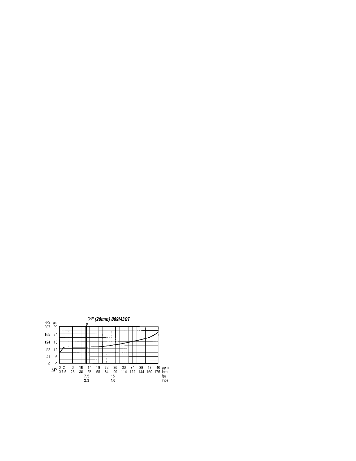
There is a pressure-reducing valve after the
backflow preventer. This valve reduces the
city water pressure to maintain the operating
pressure of the system. This valve is
adjustable from 10-35 psig with a factory
setting of 30 psig. The system pressure
varies with the height of the system. The
pressure-reducing valve setting should be set
so that the pressure at the high point in the
system is high enough to vent air from the
system (usually 4 psig). There should be air
vents at all parts in the system where air
could be trapped. If the pressure is not high
enough throughout the system, flashing
could occur in the piping or the pump could
cavitate. There is an isolation valve on the
inlet and outlet of the pressure-reducing
valve for service.
The pressure reducing valve fills the system
at a reduced rate. There is a bypass around
the pressure reducing valve for the initial fill
of the system to increase the initial fill
speed. After the initial system fill, this valve
should be closed.
Compression/Expansion Tank
As the water temperature in the system
increases, the volume that water displaces
increases. In order to compensate for these
expansion forces, a compression or
expansion tank must be used. The factory
installed tank option includes a prepressurized diaphragm compression tank
that is preset for 12 psig.
The factory pre-charge pressure may need to
be field adjusted. The tank must be precharged to system design fill pressure before
placing into operation. Remove the pipe
plug covering the valve enclosure. Check
and adjust the charge pressure by adding or
releasing air.
If the system has been filled, the tank must
be isolated from the system and the tank
emptied before charging. This ensures that
24
all fluid has exited the diaphragm area and
proper charging will occur.
If the pre-charge adjustment is necessary, oil
and water free compressed air or nitrogen
gas may be used. Check the pre-charge
using an accurate pressure gauge at the
charging valve and adjust as required. Check
air valve for leakage. If evident, replace the
Schrader valve core. Do not depend on the
valve cap to seal the leak. After making sure
the air charge is correct, replace the pipe
plug over the charging valve for protection.
Purge air from system before placing tank
into operation. All models have system
water contained behind the diaphragm.
It is recommended that the pre-charge be
checked annually to ensure proper system
protection and long life for the vessel.
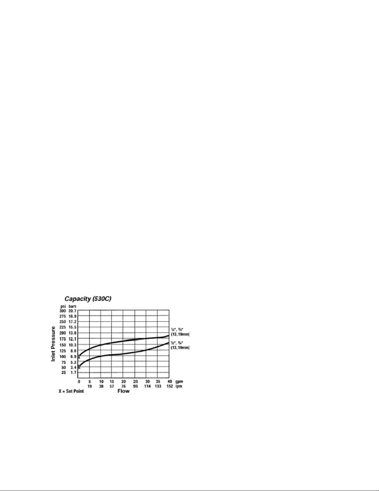
Pressure Relief Valve
Required pressure relief valve is installed in
the unit. This valve is set at 125 psig. Figure
2 shows inlet pressure versus capacity for
this pressure relief valve. See appendix for
additional information.
Figure 2 - Pressure Relief Valve
Automatic Air Vent
There is an automatic air vent installed at the
high point of the system inside the pumping
package compartment. The air vent valve
must be in the proper position for operation.
Ensure that the small vent cap is loosened
two turns from the closed position, allowing
air to be vented from the system. It is
advisable to leave the cap on to prevent
impurities from entering the valve. See
appendix for additional information.
Dual Pumps
When redundant pumping is required,
factory installed dual pumps or two single
pumps can be ordered. A dual pump is a
pump with two independent motors and
pumps in a single casing. This dual pump
has a swing split-flapper valve in the
discharge port to prevent liquid recirculation
when only one pump is operating. Isolation
valves in the casing allow one pump to be
isolated and removed for service while the
other pump is still operating.
When redundant pumping is required with
high flow rates, two independent pumps
may be installed in parallel. Each pump will
have its own suction guide/strainer,
combination valve, and isolation valves.
The controls package will activate the pump
when the unit is given a run command. If the
controls do not recognize flow in 60
seconds, the second pump will be activated
and an alarm signal will be generated. If the
second pump does not activate, the cooling
will be locked out. See appendix for
additional information.
Pressure Gauges and Thermometers
Pressure gauges and thermometers are
available as a factory installed option.
Thermometers are installed on the inlet and
outlet of the unit. One pressure gauge is
installed at each pump. This pressure gauge
is connected in three places to the water
piping before the suction guide/strainer,
after the suction guide and before the pump,

25
and after the pump. There is also a needle
valve at each of these points to isolate the
pressure. To measure the pressure at any
given point, open the needle valve at that
point and close the other two needle valves.
One gauge is used so that the calibration of
the pressure gauge is irrelevant in the
calculation of the differential pressure.
Pipe Insulation
The water piping and components on units
with pumping packages are not insulated at
the factory. Insulation should be installed on
the water piping after the system has been
checked for leaks.

26
Installation
Location
Unit Size
35-540 tons
Front -
(Controls Side)
100”
Back
100”
Ends
100”
Top
Unobstructed
All roofing work should be performed
by competent roofing contractors to
avoid any possible leakage.
CAUTION
Outdoor Mechanical Room Placement
The AAON LL Series is designed for
outdoor applications and mounting at
ground level or on a rooftop. It must be
placed on a level and solid foundation that
has been prepared to support its weight.
The placement relative to the building air
intakes and other structures must be
carefully selected. Be sure to observe the
dimensions that are on the rating plate of the
chiller for operational and service
clearances.
Table 1 - Service Clearances
Condenser coils and fans must be free of any
obstructions in order to start and operate
properly with a correct amount of airflow.
For proper unit operation, the immediate
area around condenser must remain free of
debris that may be drawn in and obstruct
airflow in the condensing section.
Consideration must be given to obstruction
caused by snow accumulation when placing
the unit.
Curb and Steel Mount Installation
Make openings in the roof decking large
enough to allow for water piping, electrical,
and gas penetrations and workspace only.
Do not make openings larger than necessary.
Set the curb to coincide with the openings.
Make sure curb is level.
Unit specific curb drawing is included with
job submittal. See SMACNA Architectural
Sheet Metal Manual for curb installation
details.
Units require rail support along all four sides
of the unit base.
When installed at ground level, a one-piece
concrete slab should be used with footings
that extend below the frost line. Care must
also be taken to protect the coil and fins
from damage due to vandalism or other
causes.
If unit is elevated a field supplied catwalk is
recommended to allow access to unit service
doors.
This unit ships with a curb gasket that is
1¼” wide and 1½” tall. It is recommended
that this or another similar gasket be used
between the curb and the unit to reduce
vibration from the unit to the building.
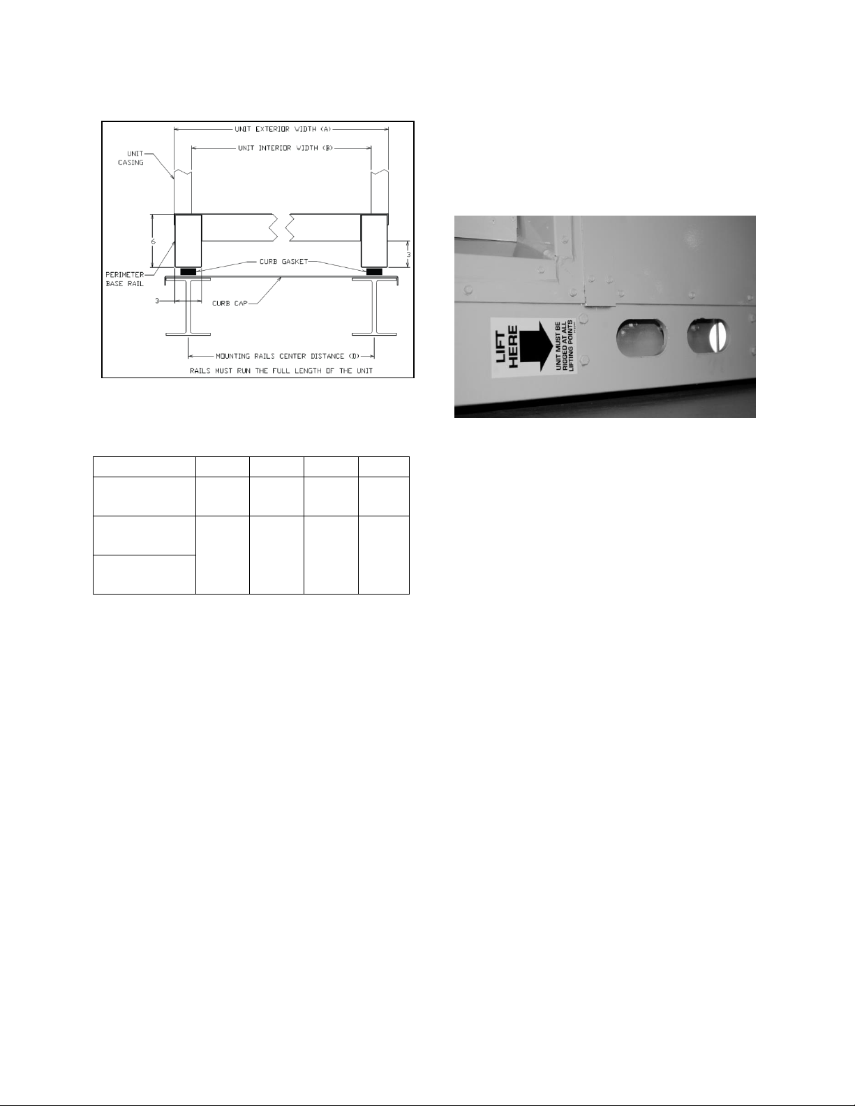
Figure 3 - Curb Mounting with Dimensions
27
Tons
A B C
D
35-115
(Scroll)
100”
96”
92”
97”
125-365
(Scroll)
142”
138”
134”
139”
90-540
(Centrifugal)
Figure 4 - Steel Mounting Rail with
Dimensions
Table 2 - Mounting Dimensions
unit is properly seated on the curb and is
level.
Do not push, pull or lift the unit from
anything other than its base.
Figure 5 - Marked Lifting Points
Lifting and Handling
If cables or chains are used to hoist the unit
they must be the same length and care
should be taken to prevent damage to the
cabinet. See Figure 6 for additional
information.
Before lifting unit, be sure that all shipping
material has been removed from unit. Secure
hooks and cables at all lifting points/ lugs
provided on the unit.
Hoist unit to a point directly above the curb
or mounting rail. Be sure that the gasket
material has been applied to the curb or
mounting rail.
Carefully lower and align unit with utility
and duct openings. Lower the unit until the
unit skirt fits around the curb. Make sure the

28
Unit must be rigged at all marked lifting points.
PVC (Polyvinyl Chloride) and CPVC
(Chlorinated Polyvinyl Chloride) are
vulnerable to attack by certain
chemicals. Polyolester (POE) oils
used with R-410A and other
refrigerants, even in trace amounts,
in a PVC or CPVC piping system will
result in stress cracking of the piping
and fittings and complete piping
system failure.
CAUTION
The chiller must be operated only
with liquid flowing through the
evaporators.
WARNING
Water Connection
Connect the supply and return water lines.
The connection size is listed on the unit
rating sheet, along with the designed
volumetric flow rate. The maximum
operating pressure for AAON LL Series
units is 125 psi.
Figure 6 - LL Series Lifting Detail
Lifting slot locations are unit specific.
Loading...