

IEEE 802.11 b/g Outdoor AP/Bridge
(Support IEEE802.11a Client Backhaul)
Models:
OWL800
V1.00
OWL2000 V1.00
HSG800
V1.00

User’s Manual
IEEE802.11 b/g Outdoor AP/Bridge (Support IEEE802.11a Client Backhaul) OWL800 / OWL2000 / HSG8 00
ENGLISH
Copyright & Disclaimer
Copyright
The contents of this publication may not be reproduced in any part or as a whole, stored, transcribed in
an information retrieval system, translated into any language, or transmitted in any form or by any means,
mechanical, magnetic, electronic, optical, photocopying, manual, or otherwise, without the prior written
permission of 4IPNET, INC.
Disclaimer
4IPNET, INC. does not assume any liability arising out the application or use of any products, or software
described herein. Neither does it convey any license under its parent rights not the parent rights of others.
4IPNET further reserves the right to make cha nges in an y products described herein without notice. The
publica tion is subject to change without notice.
Trademarks
4IPNET (4ipnet) is a registered trademark of 4IPNET, INC. Other trademarks mentioned in this publication
are used for identification purposes only and may be properties of their respective owners.

User’s Manual
IEEE802.11 b/g Outdoor AP/Bridge (Support IEEE802.11a Client Backhaul) OWL800 / OWL2000 / HSG8 00
ENGLISH
Regulatory Information
The device contains two radio modules inside. Although the model of the radio modules themselves has obtained
the FCC modular approval, independently the whole system (with the antennas and power supplier installed) has
been tested and evaluated again by a certified laboratory for the verification of FCC, CE and NCC compliances.
This device requires professional installation. Installers please refer to the caution statements unde r each
regulatory section to make sure the final installation meet the regulation within you territory. If you are in the North
America, please read the caution statements in FCC section. If you are in the Europe countries, please read the
caution statements under CE. And if you are in Taiwan, please read the Chinese statement s under NCC. In addition,
it is important for all to read the following Safety Information first.
Safety Information
All models of OWL800, OWL2000, and HSG800 have been evaluated to, and conforms to the product safety specifications of
EN:60950:2001+A11:2004.
Caution:
T his product was qualified under test conditions that included the use of the power supplying equipment. To ensure
regulatory and safety compliance, use only the provided power supplying equipment and install them properly.
To prevent electrical shock, this device may require a grounding conductor in the line cord. Connect the unit to a grounding
type ac wall outlet using the power supplying equipment supplied with the unit.
T o avoid the risk of electric shock an d for a safety outdoor installation, you may need other items, such as surge arrestors.
T o avoid the risk of electric shock from lighteni ng, do not install or use this product during an electrical storm.
Operate and in stall this product as described in this manual. This device must be installed and used in strict accordance
with the manufacturer's instructions.
Do not open th e device casing. Do not perform any servicing other than that contained in the installation and
troubleshooting instructions. Refer all servicing to qualified service personnel.

User’s Manual
IEEE802.11 b/g Outdoor AP/Bridge (Support IEEE802.11a Client Backhaul) OWL800 / OWL2000 / HSG800
ENGLISH
FCC Regulatory Information (for US)
FCC Certification
OWL800, HSG800 and OWL2000 use the same circuitry and housing except the billing and bandwidth management. The
devices
subpart C under one granted FCC-ID: VZ9090001.
operate in the 2.4 GHz and 5.725 - 5.85 bands. They are evaluated and certified according to FCC Rules Part 15
FCC Compliance Information
This device complies with Part 15 of the FCC Rules. Operation is subject to the following two conditions: (1) This device may not
cause harmful interference, and (2) this device must accept any interference received, including interference that may cause
undesired operation.
FCC Radiation Exposure Statement:
This equipment complies with FCC radiation exposure limits set forth for an uncontrolled enviro nment.
For complying with the
operating
configurations must be satisfied:
FCC radio frequency exposure requirements, the following antenna install ation and device
The device must be professionally installed on a fixed or permanent structure with a separation distance of at
least 20cm from all persons.
This device and its antennas must not be co-located or operating in conjunction with any other antenna or
transmitter.
Any changes or modifications not expressly approved by the party responsible for compliance could void the
user’s authority to operate this equipment.
FCC Class B Statement
This equipment has been tested and found to comply with the limits for a Class B digital device, pursuant to Part 15 of the FCC
Rules. These limits are designed to provide reasonable protection against harmful interference in a residential installation. This
equipment generates and uses radio frequency energy and, if not installed and used in accordance with the instructions, may
cause interference to radio communications. However, there is no guarantee that interference will not occur in a particular
installation. If this equipment does cause interference to radio or television reception, which can be determined by turning the
equipment off and on, the user is encouraged to try to correct the interference by one or more of the following measures:
Reorient or relocate the receiving antenna or cable input device.
Increase the separation between the equipment and receiver.
Connect the eq uipment into an outlet on a circuit different from that to which the receiver is connected.
Consult the dealer or an experienced radio/TV technician for help.

User’s Manual
IEEE802.11 b/g Outdoor AP/Bridge (Support IEEE802.11a Client Backhaul) OWL800 / OWL2000 / HSG800
ENGLISH
CE Regulatory Information (for Europe)
Declaration of Conformity with Regard to the 1999/5/EC (R&TTE Directive) for
European Community, Switzerland, Norway, Iceland, and Liechtenstein
Models: OWL800, HSG800 and OWL2000
All three models have been tested and passed the requirements of the following standards, and hence fulfills the EMC and safety
requirements of R&TTE Directive within the CE marking requirement.
• Radio: EN 300.328
• Radio: EN 50392
• EMC: EN 301.489-1
• EMC: EN 55022
:2006
:2004
, EN 301.489-17
:2005
Class B, EN 55024
:2006
:2002
:1998
,
+ A1
:2001
+ A2:
including the followings:
2003
EN 61000-3-2, EN 61000-3-3.
EN 61000-4-2, EN 61000-4-3, EN 61000-4-4,
EN 61000-4-5, EN 61000-4-6, EN 61000-4-11
• Safety: EN 60950-1
:2001
+ A11
:2004
,
Caution:
This declaration is only valid for configurations (combinations of software, firmware, and hardware) provided and supported
by 4ipnet Inc. The use of software or firmware not provided and supported by 4ipnet Inc. may result in the equipment no
longer being compliant with the regulatory requirements.
European standards dictate maximum radiat ed transmit power of 100mW EIRP and frequency range 2.400-2.4835 GHz.
This equipment is intended to be used in all EU and EFTA countries. Outdoor use may be restricted to certain frequencies
and/or may require a license for operation. Contact your local regulatory authority for compliance.
User’s Manual
IEEE802.11 b/g Outdoor AP/Bridge (Support IEEE802.11a Client Backhaul) OWL800 / OWL2000 / HSG800
NCC Regulatory Information (for Taiwan)
NCC 基本規定項目 :
根據 NCC 低功率電波輻射性電機管理辦法 規定:
ENGLISH
第十二條
第十四條
經型式認證合格之低功率射頻電機,非經許可,公司、商號或使用者均不得擅自變更頻率、加
大功率或變更原設計之特性及功能。
低功率射頻電機之使用不得影響飛航安全及干擾合法通信;經發現有干擾現象時應立即停用,
並改善至無干擾時方得繼續使用。
前項合法通信,指依電信法規定作業之無線電通信。
低功率射頻電機須忍受合法通信或工業、科學及醫療用電波輻射性電機設備之干擾。
NCC 其他注意項目 (NCC Caution) :
一、本產品(OWL800, HSG800, OWL2000)及外接天線僅限於專業安裝,並限於固定式、點對點之操作。本產品是設
計為專業用、防水、防風、防銹、堅固之工業級產品;其銷售對象限於有發射器專業安裝技術之工程單位或無線系統
之專業整合商。
二、本產品(OWL800, HSG800, OWL2000)內建兩個無線模組(型號CM9),其最高輸出功率為19dBm。設定介面所提
供的功率變更只能用於調降發射功率,也就是說,設定在最高時(Highest),只會達19 dBm,設定的改變不會加大無
線模組之發射功率。
三、本產品(OWL800, HSG800, OWL2000)雖然有介面可改設內建無線模組的發射頻道,以避免與其它鄰近無線設備
衝突;但介面上所可選之頻道,是根據販售當地法令有所限制。例如,在台灣市場及在北美市場的產品,2.4G範圍只
有11個頻道在介面上可選,使用者無法將發射頻道設為其他在歐、日可選而在台灣所不允許之頻道。
四、本產品(OWL800, HSG800, OWL2000)附有隨機所附手冊,包含以上所有繁體中文警告訊息。專業使用者與安裝
者有責遵循NCC規定。專業使用者與安裝者若有自行變動產品,違規使用當地法規不允許頻率、功率,必須承擔法律
責任並負責賠償受害用戶之一切損失。

User’s Manual
OWL800 / OWL2000 / HSG800 ENGLISH
Table of Contents
Copyright & Disclaimer.....................................................................................................................................i
Regulatory Information....................................................................................................................................... ii
FCC Regulatory Information (for US)...................................................................................................................... iii
CE Regulatory Information (for Europe)...................................................................................................................iv
NCC Regulatory Information (for Taiwan).................................................................................................................v
1. Before You Start............................................................................................................................3
1.1 Preface ....................................................................................................................................................3
1.2 Document Convention............................................................................................................................3
2. System Overview ...........................................................................................................................2
2.1 Introduction of OWL800 ........................................................................................................................2
2.2 System Concept ......................................................................................................................................2
3. Base Installation...........................................................................................................................4
3.1 Hardware Installation..............................................................................................................................4
3.1.1 Package Contents..........................................................................................................................................4
3.1.2 Panel Function Descriptions .........................................................................................................................5
3.1.3 Hardware Installation....................................................................................................................................6
3.2 Software Configuration...........................................................................................................................7
3.2.1 Instruction of Web Management Interface....................................................................................................7
3.2.2 User Login Portal Page...............................................................................................................................10
3.2.3 Basic Configuration....................................................................................................................................12
3.2.4 Common Settings........................................................................................................................................16
4. Menu Configuration (AP & Gateway Mode).............................................................................20
4.1 System...................................................................................................................................................24
4.1.1 General........................................................................................................................................................24
4.1.2 Network Interface .......................................................................................................................................27
4.1.3 Management................................................................................................................................................32
4.1.4 VLAN Overview.........................................................................................................................................34
4.1.5 VLAN Configuration..................................................................................................................................36
4.1.6 Walled Garden.............................................................................................................................................39
4.1.7 Mode...........................................................................................................................................................41
4.2 AP .........................................................................................................................................................42
4.2.1 Overview.....................................................................................................................................................42
4.2.2 General........................................................................................................................................................45
4.2.3 VAP Configuration......................................................................................................................................46
4.2.4 Security.......................................................................................................................................................47
4.2.5 Advanced....................................................................................................................................................51
4.2.6 Access Control............................................................................................................................................52
© 2008 4IPNET, INC.
1

User’s Manual
OWL800 / OWL2000 / HSG800 ENGLISH
4.3 WDS......................................................................................................................................................54
4.3.1 Overview.....................................................................................................................................................54
4.3.2 General........................................................................................................................................................55
4.3.3 WDS Configuration....................................................................................................................................56
4.3.4 WDS Discovery..........................................................................................................................................58
4.4 User.......................................................................................................................................................59
4.4.1 Local ...........................................................................................................................................................59
4.4.2 RADIUS......................................................................................................................................................62
4.4.3 On-demand..................................................................................................................................................64
4.4.4 Policy..........................................................................................................................................................69
4.4.5 Firewall.......................................................................................................................................................71
4.4.6 Route...........................................................................................................................................................73
4.4.7 802.1X.........................................................................................................................................................74
4.5 Utilities..................................................................................................................................................75
4.5.1 Change Password........................................................................................................................................75
4.5.2 Import & Export..........................................................................................................................................76
4.5.3 Backup & Restore.......................................................................................................................................77
4.5.4 System Upgrade..........................................................................................................................................78
4.5.5 Reboot.........................................................................................................................................................79
4.5.6 Scan.............................................................................................................................................................80
4.5.7 Upload Certificate.......................................................................................................................................81
4.6 Status.....................................................................................................................................................82
4.6.1 Overview.....................................................................................................................................................82
4.6.2 WDS List ....................................................................................................................................................85
4.6.3 Antennas .....................................................................................................................................................86
4.6.4 Associated Clients....................................................................................................................................... 87
4.6.5 Event Log....................................................................................................................................................88
4.6.6 Online Users ...............................................................................................................................................89
4.6.7 User Log .....................................................................................................................................................90
Appendix A. Session Limit and Session Log.......................................................................................91
Appendix B. 802.1X Support................................................................................................................93
© 2008 4IPNET, INC.
2

User’s Manual
OWL800 / OWL2000 / HSG800 ENGLISH
1. Before You Start
1.1 Preface
This manual is intended for using by system integrators, professional field engineers and network administrators to
help them set up OWL800 for their network deployment. It contains step by step pro ced ures and pictures to guide
users with basic network system knowledge to complete the installation.
The IEEE 802.11 b/g Outdoor AP/Bridge (Support IEEE802.11a Client Backhaul) is a rugged multi-mode
dual-radio outdoor access point, specifically designed for building municipal or campus wide wireless networks in
harsh outdoor environments. The entry model OWL800 is deployed as a traditional multi-wireless Access Point (AP)
or a backhaul. The second model HSG800, can be used as an Outdoor Wireless Gateway with built-in Hotspot
Access Control and Billing features. The OWL2000 is purely used for building point-to-point bridges. Some of the
optional features (such as billing) are on or off depending on the model. Please refer to the optional feature list s
provided separately. In this manual, all the optional featured are covered. In the following manual, we will refer the
device as “OWL800” or “the system” for the convenience.
Model Description
OWL800 This is the base model. Its firmware can be upgraded to be HSG800 or OWL2000
when optional software feature is purchase. The base firmware support AP/Bridge
and Gateway operation mode.
HSG800 This model consists of all the features of OWL800, plus the Hotspot billing &
payment function.
OWL2000 This model turn an OWL800 first radio card from an AP into another
backhaul/bridge radio card. Traffic over multiple air links will be aggregated to
achieve better throughput and reliability.
1.2 Document Convention
The following information provides the details of conventions used in this manual. In the following manual, we will
refer the device as “OWL800” or “the system” for the convenience.
For cautionary statements or warning requiring special attention by readers, a text box with italic font will be used:
Warning: For security purposes, you should immediately change the administrator’s password.
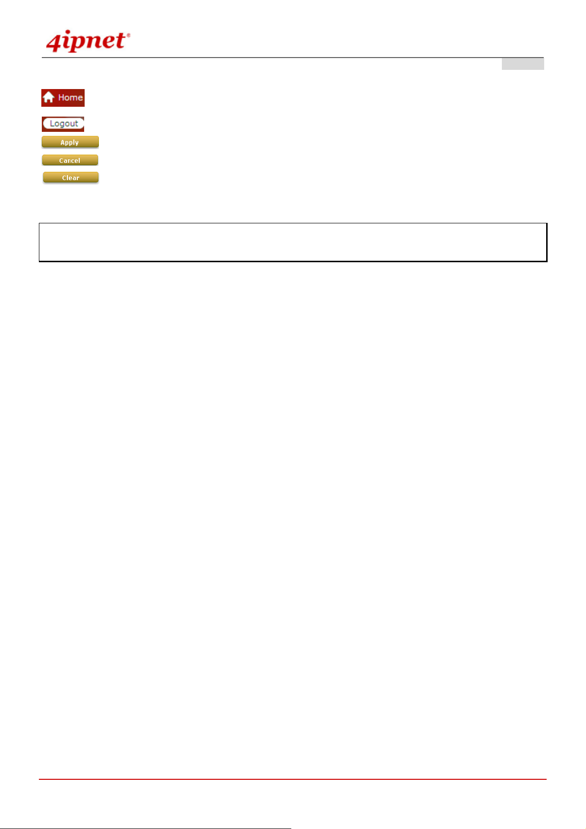
When any of the button and symbol shown below is selected, the following action will be executed accordingly:
© 2008 4IPNET, INC.
3
User’s Manual
OWL800 / OWL2000 / HSG800 ENGLISH
Return to system Home page.
Logout the system.
Apply all configurations.
Clear all configurations and not to activate them.
Clear settings entered by clicking this button.
* The red asterisk indicates information in this field is compulsory.
Note: Screen captures and pictures used in this manual may be displaye d in part or in whole or similar products,
and may vary or differ slightly from the actual product, depending on versio ning and menu accessed.
© 2008 4IPNET, INC.
4

User’s Manual
OWL800 / OWL2000 / HSG800 ENGLISH
2. System Overview
2.1 Introduction of OWL800
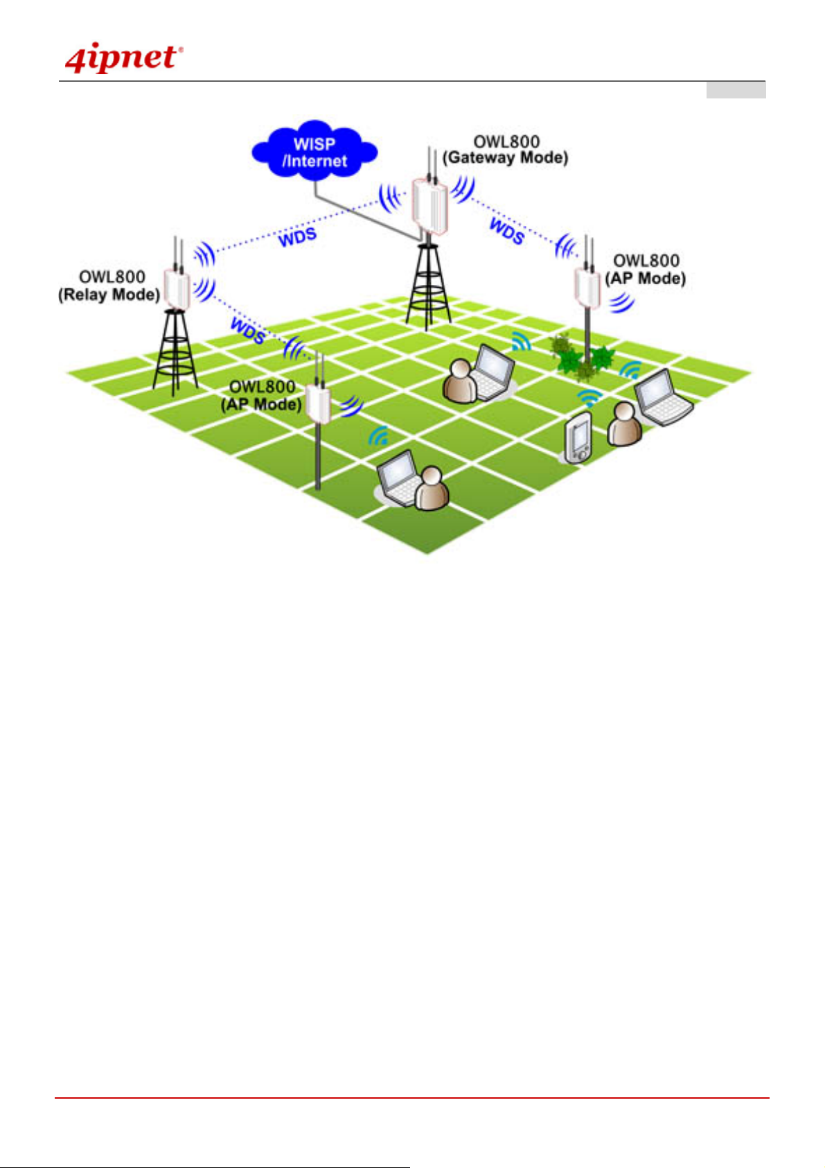
The IEEE 802.11 b/g Outdoor AP/Bridge (Support IEEE802.11a Client Backhaul) series (referred as OWL800 or
the system in this manual) is a rugged multi-mode dual-radio outdoor access point, specifically desi gned for building
municipal or campus wide wireless networks in ha rsh outdoor environments. There are two System Modes that can
be used for dual purposes. First, it can be deployed as a traditional multi-wireless Access Point (AP) or a Relay.
Secondly, it can be used as an Outdoor Wireless Gateway with Bui lt-in Hotspot Access Control and Billing features
(* an optional feature).
The metal sealed OWL800 is weatherproof. Coming with a mounting kit, it can be moun ded on a pole or on wall.
This Quick Installation Guide provides instructions and reference material for getting st arted with OWL800 (as well
as the other two models).
OWL800’s rust-free die-cast Aluminum housing is IP68 compliant and high wind load resilient. All the components
are designed to operate in a wide range of temperature. The on-board surge protection provides the device up to
15KV surge immunity. The OWL800 delivers an excellent outdoor WLAN solution.
2.2 System Concept
The System contains two radio modules. Two 100mW modules are WNC’s CM9, which are tested to be modular
FCC and CE compliant. The first card is mainly used for serving clients at “b/g” mode. The second Radio module is
used for building point-to-point or the back haul connection in “a” mode.
OWL800 is a cost-effective choice as well as a flexible solution for constructing serviceable wireless network.
Designed by the leading hotspot appliance provide r, 4ipnet OWL800 behaves more than a wireless router when it is
in Gateway mode. Not only it supports NAT, DHCP and firewall, it also has AAA features of a hotspot gateway,
including UAM web login portal and billing plans. Standalone it has local user database for authentication, while at
the same time it can play the role of RADIUS-NAS, authenticating users against ISP’s RADIUS server in the data
center.
© 2008 4IPNET, INC.
2
User’s Manual
OWL800 / OWL2000 / HSG800 ENGLISH
Multi-mode in Operation
© 2008 4IPNET, INC.
3
User’s Manual
OWL800 / OWL2000 / HSG800 ENGLISH
3. Base Installation
3.1 Hardware Installation
3.1.1 Package Contents
The standard package of OWL800 includes:
y OWL800 x 1
y Quick Installation Guide (with User’s Manual and QIG) x 1
y CD-ROM x 1
y RJ45-RS232 Console Cable x 1
y PSE x 1
y Power cord x 1
y Mounting Kit x 1
y Waterproof Connector Pack x 2
y Rubber antenna x 4
Note: It is recommended to keep the original packing materials in case of product service req uirements. Any
returned product should be packed according to its original package conte nt, together with its relevant packing
materials used for protecting the equipment from damage during delivery.
© 2008 4IPNET, INC.
4
User’s Manual
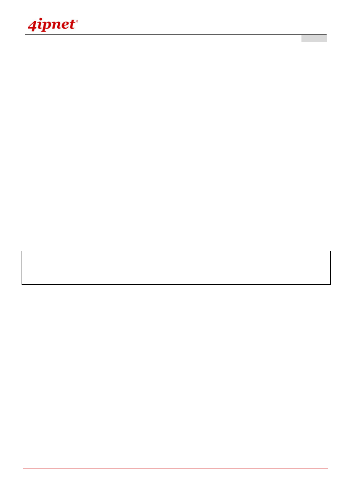
3.1.2 Panel Function Descriptions
Lower Panel
PoE1 / PoE2: For connecting to the PSE
o In AP/Relay mode, PoE1 and PoE2 work as LAN ports.
o In Gateway mode, PoE1 works as a WAN port and PoE2 works as a LAN port.
OWL800 / OWL2000 / HSG800 ENGLISH
Console:
o Attach the RJ45-RS232 console cable here.
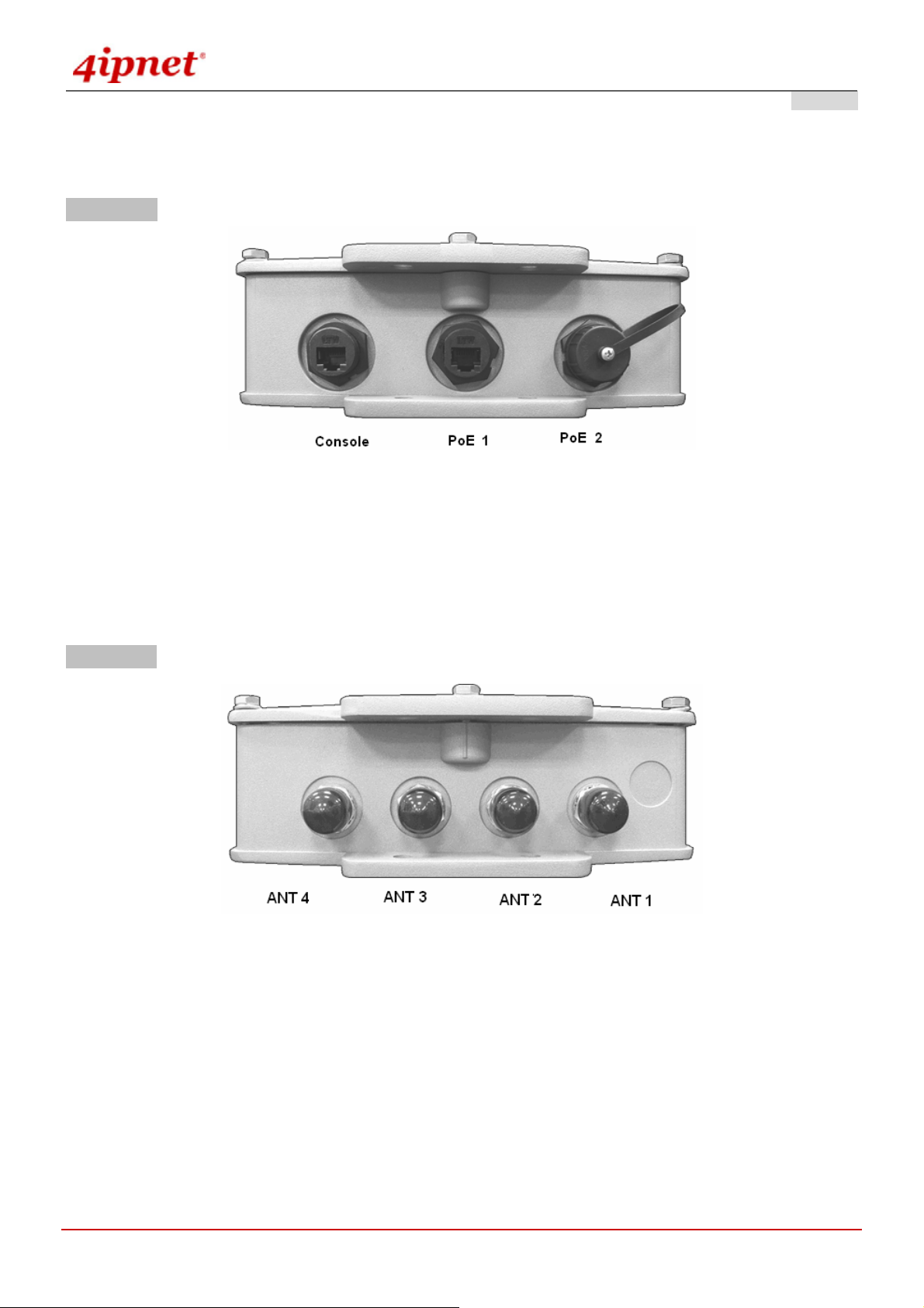
Upper Panel
This picture represents ANT 1 ~ ANT 4 connectors from right to left when OWL800 chassis (with Mylar) is faced up.
Each of the two radio module (CM9) inside has two antenna connectors for antenna diversity. The required
antenna is antenna ANT1 and antenna ANT2. ANT1 is connected to the “Main” contact point of the first radio
module. ANT2 is connected to the “Main” contact of the second module.
The other two antennas are optional for antenna diversity. The antenna ANT3 is connected to the “Aux” contact point
of the first radio module, while ANT4 is conne cted to the “Aux” contact point of the second radio module. For further
details on antenna, please refer to the section 4.6.3..
© 2008 4IPNET, INC.
5
User’s Manual
OWL800 / OWL2000 / HSG800 ENGLISH
3.1.3 Hardware Installation
Please follow the steps mentioned below to complete the hardware of OWL800 for configuration.
1. Connect antennas to the required ANT1 and ANT3, which lead to the “Main” contacts of the two radio cards.
2. (Optional) Connect antennas to the required ANT3 and ANT4, which lead to the “Aux” contacts of the two radio
cards.
3. Connect the PSE (POWER & DATA OUT) to the PoE 2 connector on the lower p anel.
4. Connect one end of an Ethernet cable to the PSE (DATA IN) and the other end to a computer.
5. Connect the power cord to the PSE.
6. Power on the PSE in order to supply power to OWL800.
7. Note You must be professional to use a different replacement antenna, and you must following the
code/regulation of your region/country for the installation.
Now, the Hardware Installation has been completed and ready for configuration. It is easier to following the Quick
Installation Guild for the first time to configure the necessary network parameters, such as the IP address.
Note: It is recommended to keep the original packing materials in case of product service req uirements. Any
returned product should be packed according to its original package conte nt, together with its relevant packing
materials used for protecting the equipment from damage during delivery.
© 2008 4IPNET, INC.
6
User’s Manual
OWL800 / OWL2000 / HSG800 ENGLISH
3.2 Software Configuration
3.2.1 Instruction of Web Management Interface
OWL800 provides the web management interface for configuration. OWL800 is a multi-mode system which can be
configured as either an access point (AP/Relay Mode with RF1 in AP ), a relay (AP/Relay Mode with RF1 in WDS),
or a gateway that clients can associate on it based on your needs. It is required to follow the respective installation
procedures provided to properly set up the desired mode of this system.
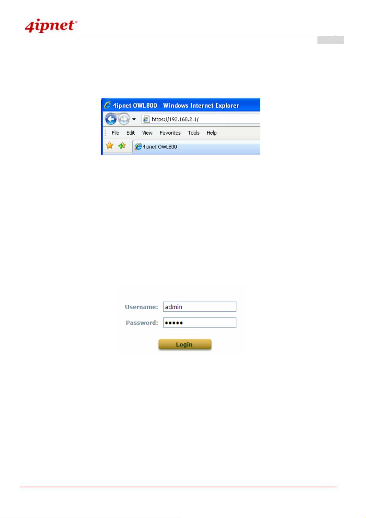
After completing hardware installation, the administrator can configure the OWL800 via web browsers.
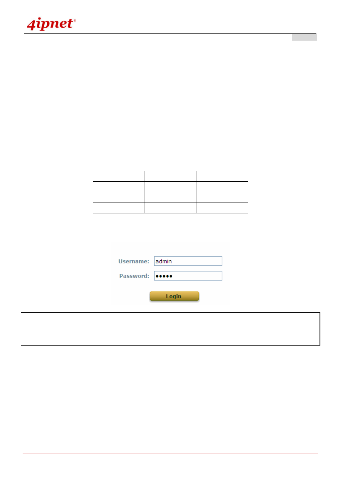
The default IP address and Subnet Mask of dif f erent modes are as follows:
Mode AP/Relay Gateway
IP Address
Subnet Mask
Default Gateway
Enter “admin” as the default Username and “admin” as the default Password and click Login to continue.
192.168.2.1 192.168.1.1
255.255.255.0 255.255.255.0
192.168.2.254 192.168.1.254
Note: If you are unable to get to the login screen, please check the IP address used. The IP address should be in
the same subnet of the default gateway. For using static IP in TCP/IP setting, set a static IP address such as
192.168.1.x for your network interface and then open a new browser again.
© 2008 4IPNET, INC.
7
User’s Manual
OWL800 / OWL2000 / HSG800 ENGLISH
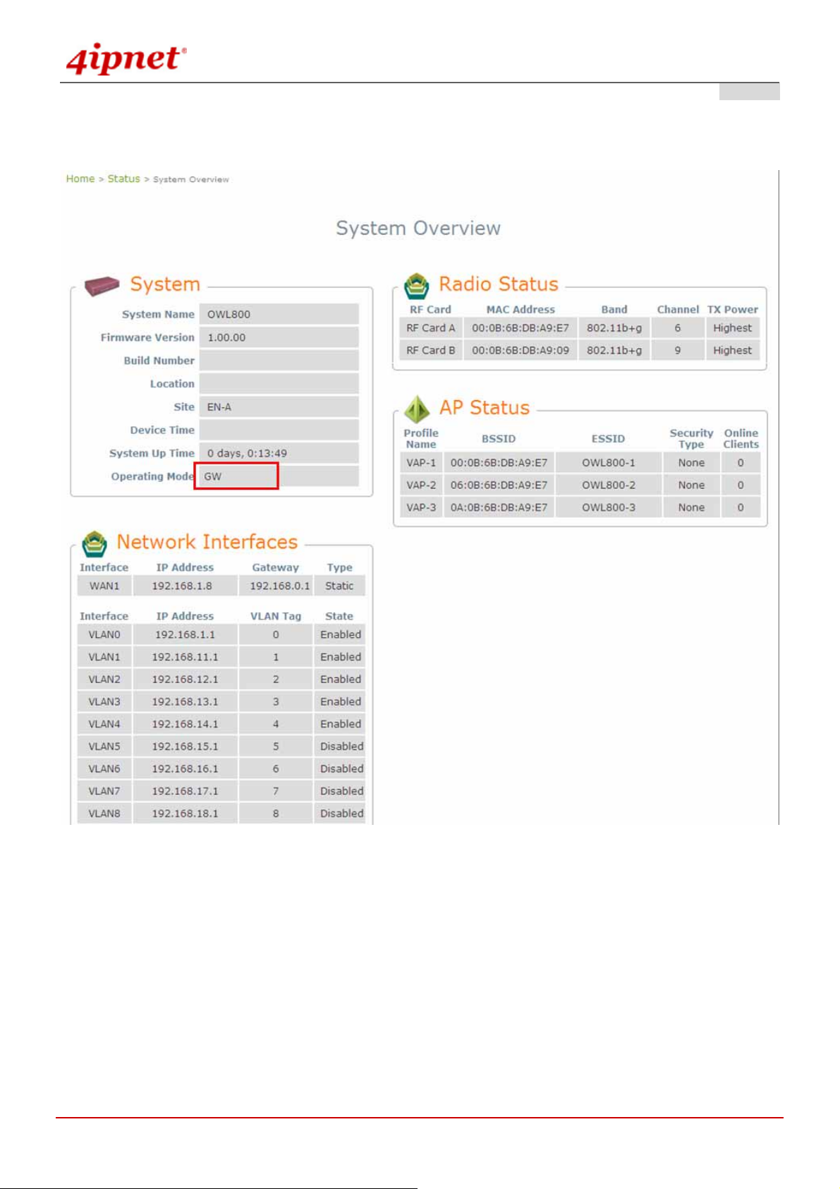
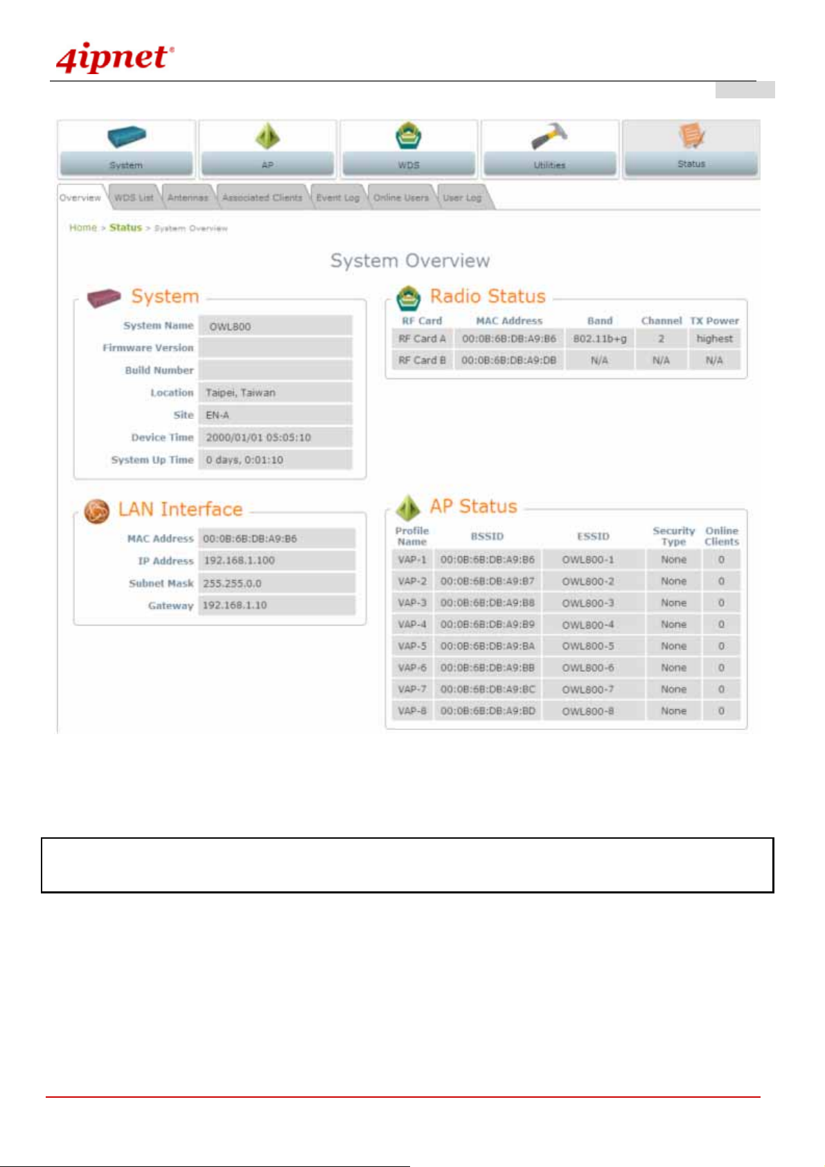
¾ Main Menu: provides detailed configuration pages for administrators to configure the system manually. Please
refer to Section 4. - Main Menu for more information.
Gateway Mode
© 2008 4IPNET, INC.
8
User’s Manual
OWL800 / OWL2000 / HSG800 ENGLISH
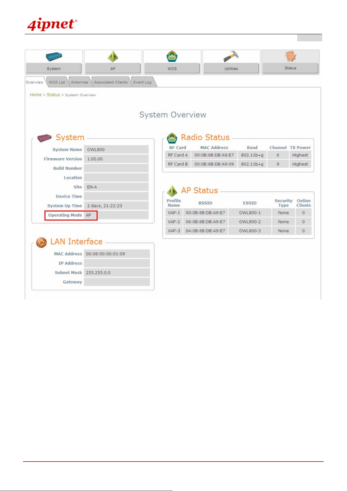
AP Mode
© 2008 4IPNET, INC.
9
User’s Manual
OWL800 / OWL2000 / HSG800 ENGLISH
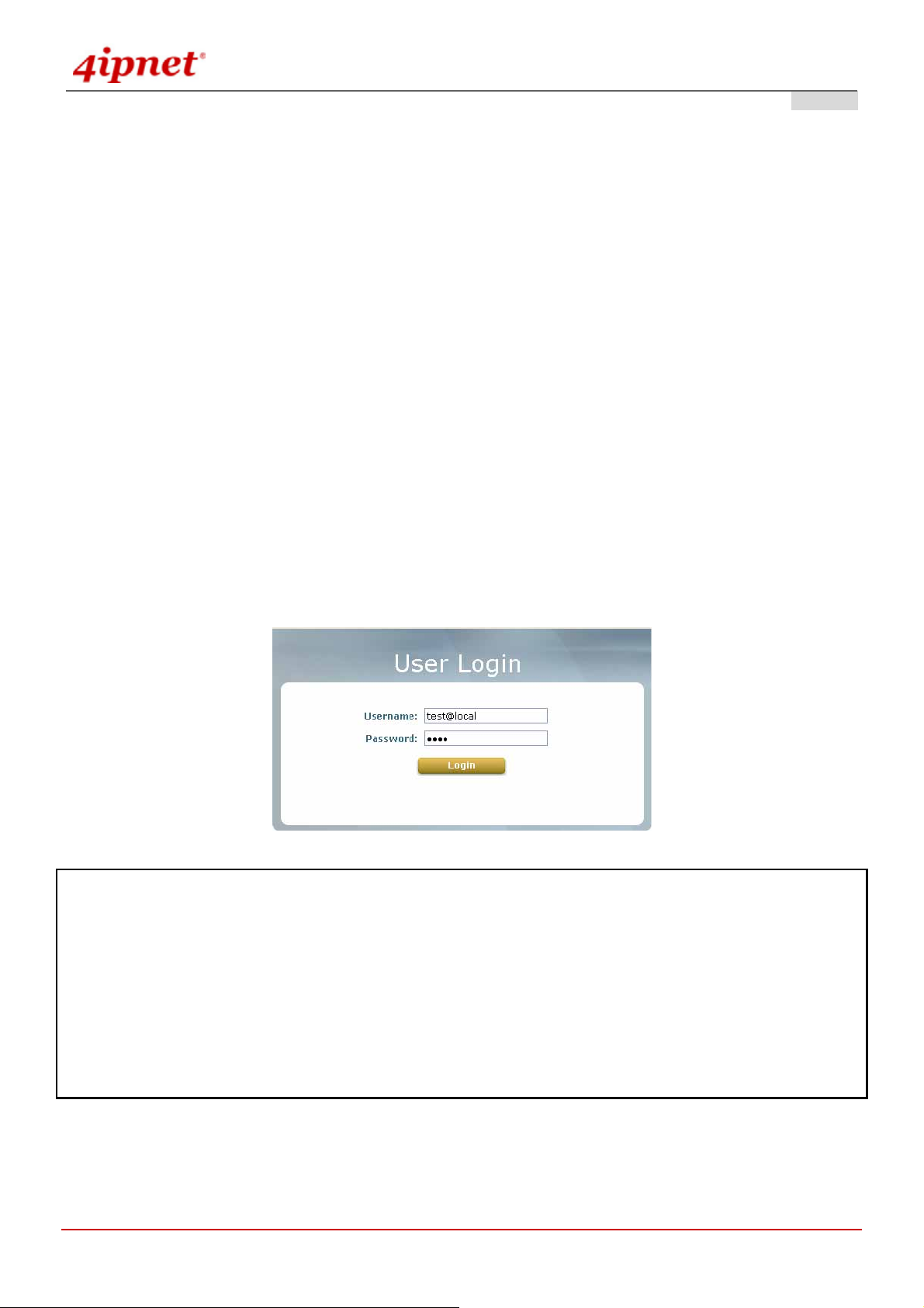
3.2.2 User Login Portal Page
To be granted the network access via OWL800, clients have to be authenticated by the system first via entering the
correct usernames and passwords in the User Login Portal Page as shown below. The local account generated
previously in the Setup Wizard section is used as the example to illustrate this procedure.
Step 1:
Connect a client’s PC to OWL800 via any one of the LAN Ports. The IP address will be assigned to the PC
automatically via DHCP.
Step 2:
Verify New Local Account:
To verify whether the configuration with DHCP via the Setup Wizard is done properly, firstly, connect a client’s PC
from the system to LAN1 Port. The device will get an IP address automatically via DHCP.
Next, open a web browser and access any URL, and then the default User Login Page will appear.
Enter the username and password of the local user account generated by Setup Wizard previously (e.g.
“test@local” as the Username and “test” as the Password), then click Login.
Note:
1. OWL800 supports both local built-in user database and external authenti catio n database, such as RADIUS and
LDAP. Thus, by entering the full username, the system will automatically identify which authentication server is used.
Exception: The postfix can be omitted only when the default authentication option is used; “local” is the default
authentication option of the system. You may therefore enter either ‘test’, or ‘test@local in the username field for
the previous example.
2. The format of a valid Username is: UserId@postfix, where UserId is the User ID, and postfix is a name for the
chosen authentication option.
© 2008 4IPNET, INC.
10
User’s Manual
OWL800 / OWL2000 / HSG800 ENGLISH
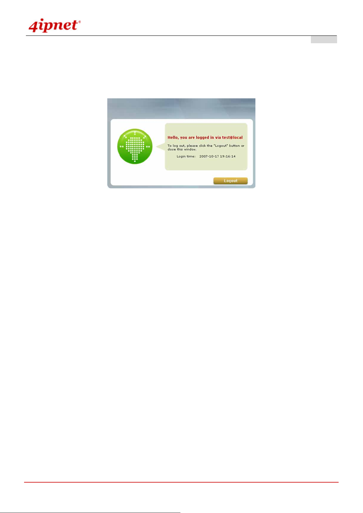
Step 3:
The Login Success Page will appear after a client is authenticated by the system and logs in successfully. In the
meantime, successful login means OWL800 has been installed and configured properly.
© 2008 4IPNET, INC.
11
User’s Manual
OWL800 / OWL2000 / HSG800 ENGLISH
3.2.3 Basic Configuration
<AP/Relay Mode>
After completing hardware installation, the administrator can configure the OWL800 via web browsers.
If the IP address of the administrator’s PC is within the same subnet as OWL800’ s, the n assigning a st ati c IP address
within the same subnet as OWL800’s to the administrator’s PC is needed in order to get Administrator Login Page.
The following IP address is listed as an example:
IP Address: 192.168.2.10
Subnet Mask: 255.255.255.0
Default Gateway: 192.168.2.254
Once OWL800 has been connected, the Administrator Login Page will appear. Enter “admin” for both the default
user name and password in the Username and Password fields, and then click the OK button to log in.
Username: admin
Password: admin
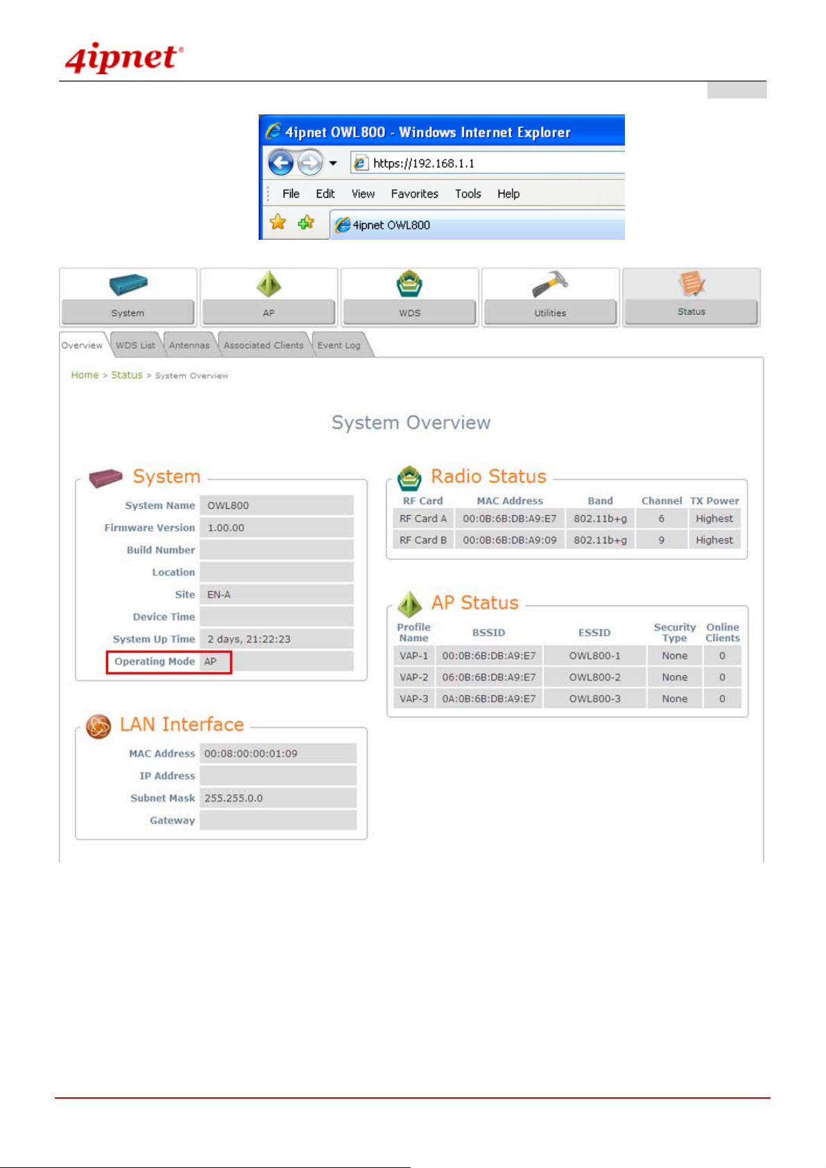
After successfully logging into OWL800, the System Overview page of the web management interface will appear.
© 2008 4IPNET, INC.
12
User’s Manual
OWL800 / OWL2000 / HSG800 ENGLISH
AP Mode
To logout, simply click the Logout icon on the upper right corner of the web management interface to return to the
Administrator Login Page.
Note: By default, the system is in AP/Relay mode. Therefore, the administrator must login to the system in AP/Relay
mode at the first time and then be able to switch the system to the desired mode afterwards.
© 2008 4IPNET, INC.
13
User’s Manual
OWL800 / OWL2000 / HSG800 ENGLISH
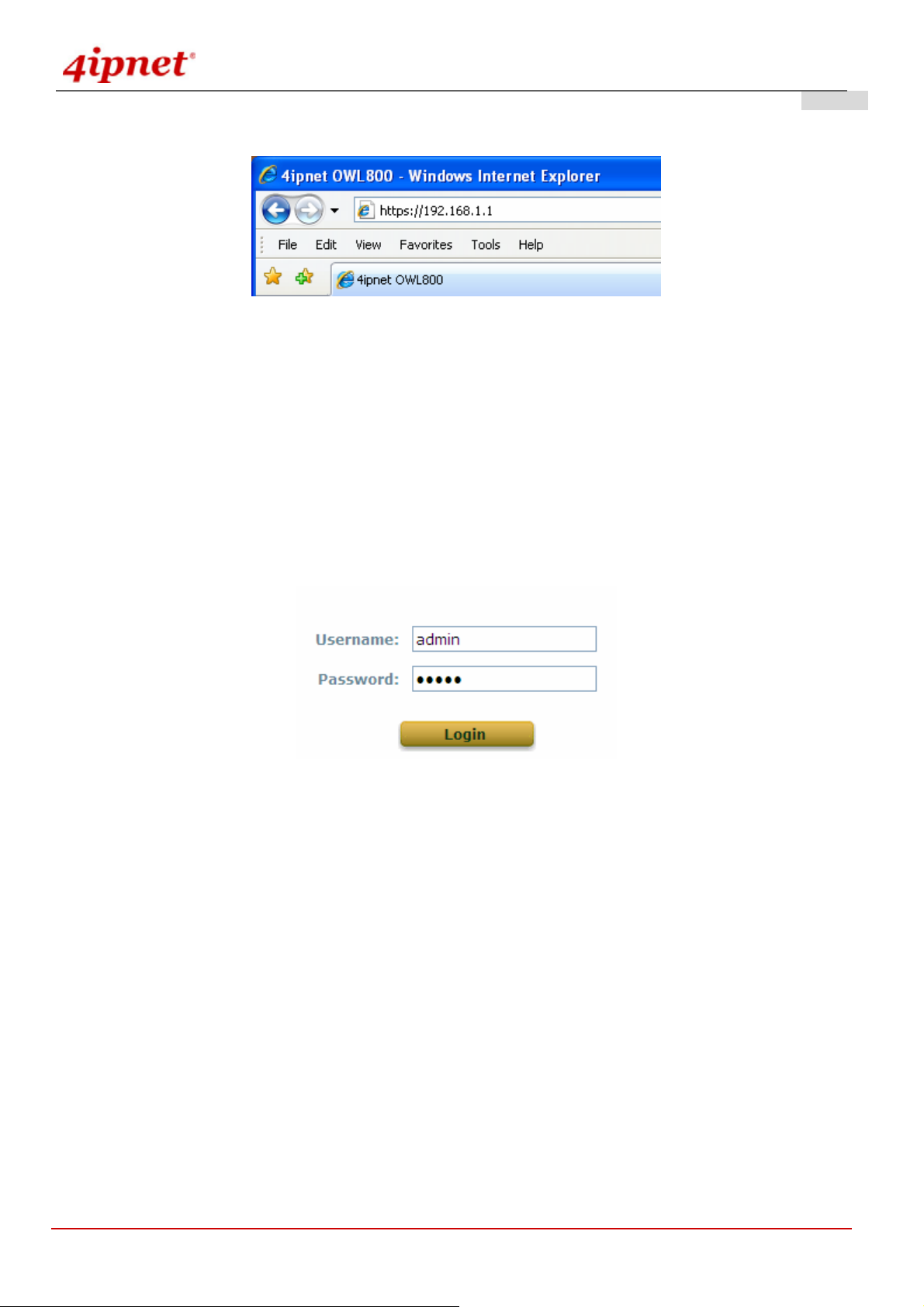
<Gateway Mode>
If the IP address of the administrator’s PC is not assigned via DHCP within the same subnet as OWL800’s, then a
static IP address assigned to the administrator’s computer within the same subnet as OWL800’s is needed. The
following IP address is listed as an example:
IP Address: 192.168.1.10
Subnet Mask: 255.255.255.0
Default Gateway: 192.168.1.254
Once OWL800 has been connected, the Administrator Login Page will appear. Enter “admin” for both the default
user name and password in the User name and Password fields, and then click the OK button to log in.
User name: admin
Password: admin
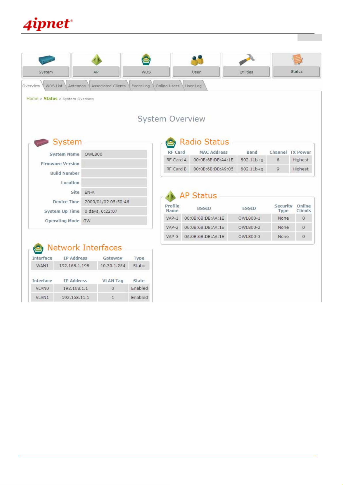
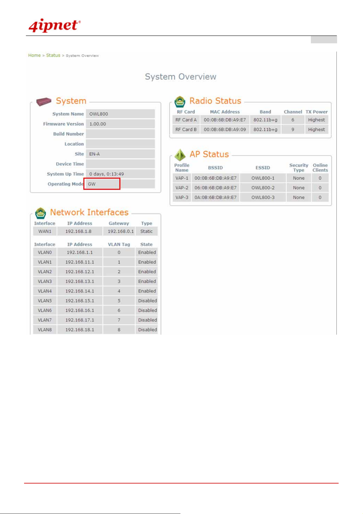
After successfully logging into OWL800, the System Overview page of the web management interface will appear.
© 2008 4IPNET, INC.
14
User’s Manual
OWL800 / OWL2000 / HSG800 ENGLISH
Gateway Mode
To logout, simply click the Logout icon on the upper right corner of the web management interface to return to the
Administrator Login Page.
© 2008 4IPNET, INC.
15
User’s Manual
OWL800 / OWL2000 / HSG800 ENGLISH
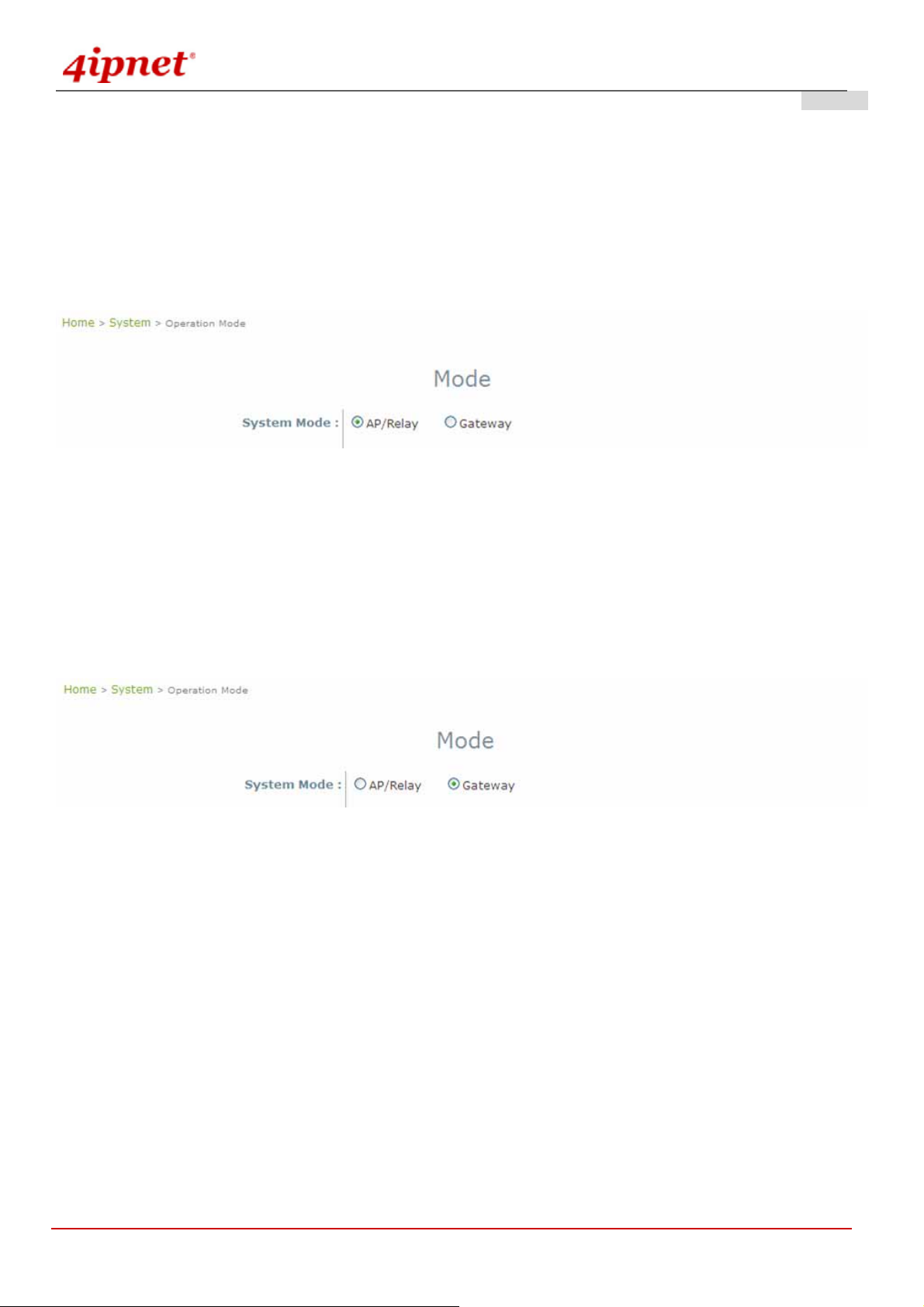
3.2.4 Common Settings
System Mode Configuration:
1) Change Syst em Mode by clicking on the System menu item.
2) Select Mode from submen u item.
3) Select desired System mo de - either AP/Relay or Gateway mode, and then click on Apply to confirm the
change.
AP Mode
When OWL800 is set in AP/Relay mode, it is a layer2 IP device like a normal AP. No IP sharing (NAT) and routing
feature are support.
When OWL is set in Gateway mode, it is a layer3 IP device. Like an AP router, OWL800 in the gateway mode
support IP sharing (NAT). Its POE1 port is treated as the uplink.
Gateway Mode
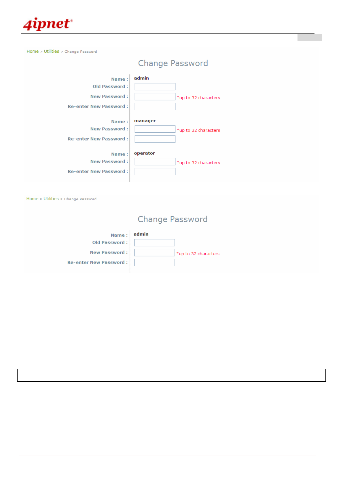
Change Password:
1) Change administrator's password by clicking on the Utilities menu item.
2) Select Change Password from submenu item.
3) Enter new password. Supply new password with up to 32 characters, and then click on Apply to confirm the
change.
© 2008 4IPNET, INC.
16
User’s Manual
OWL800 / OWL2000 / HSG800 ENGLISH
Gateway Mode
AP Mode
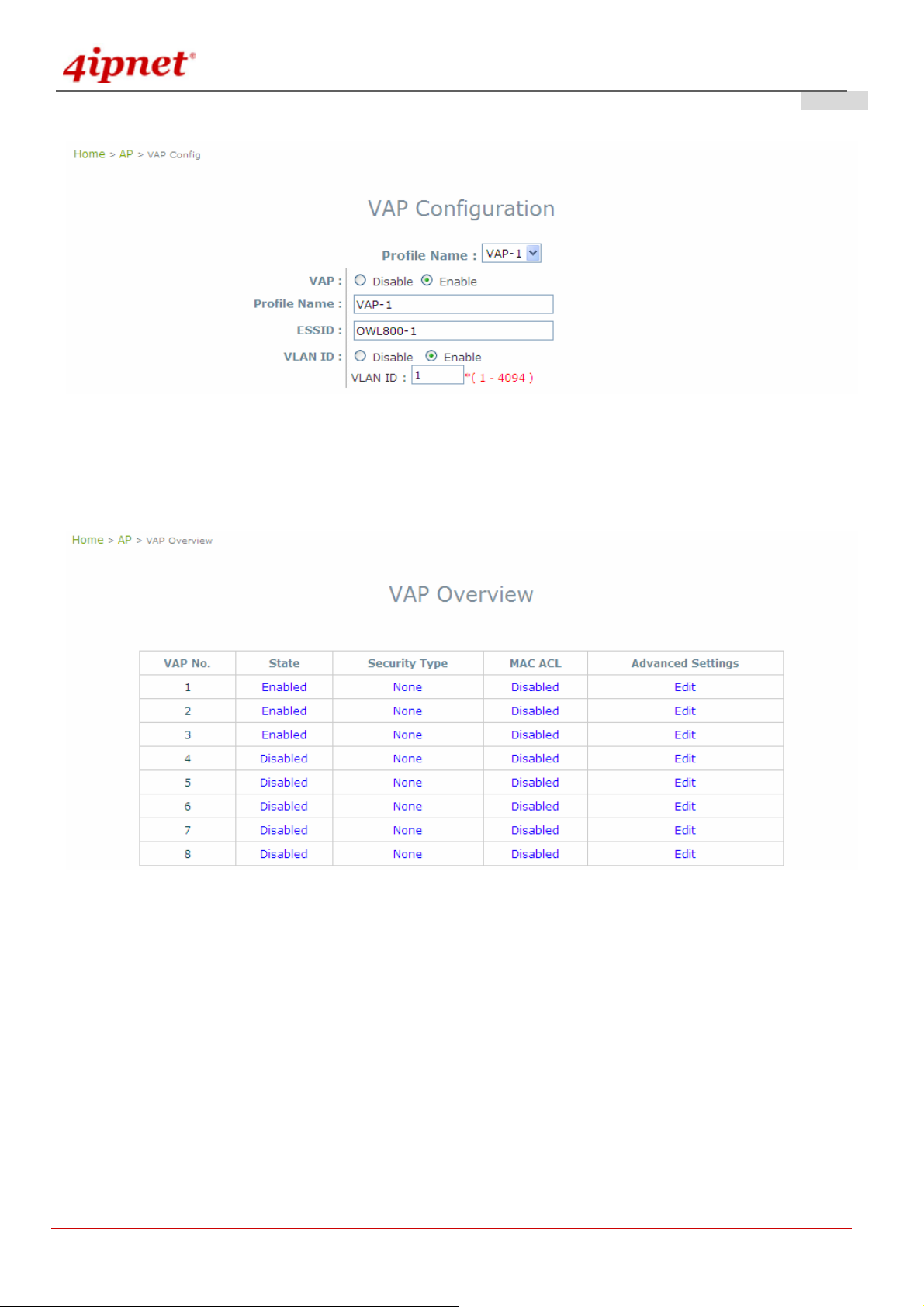
Check VAP Profile Settings
1) Click on the AP menu item.
2) Select VAP Configuration from submenu item.
3) Administrator can enable or disable specific VAP from the drop down list of “Profile Name”.
4) Set desired ESSID.
5) Disable VLAN ID means untagged when this VAP is enabled. Set a VLAN ID if this VAP is tagged.
Note: To configure the rest of the profiles, please follow the same steps as illustrated for VAP-1.
© 2008 4IPNET, INC.
17
User’s Manual
OWL800 / OWL2000 / HSG800 ENGLISH
Gateway & AP Mode
Check AP Status
After finishing the settings, the enabled virtual AP should appear in the virtual AP list showing enabl ed state.
Gateway & AP Mode
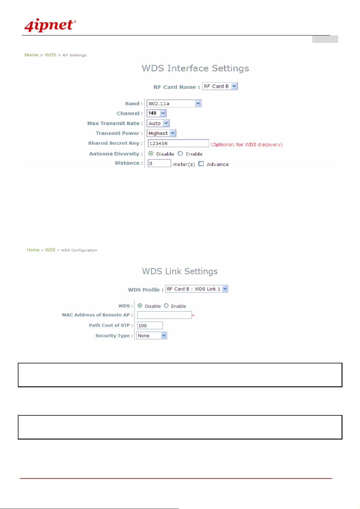
Configure General WDS Settings
1) Click on the WDS menu item. Select General submenu.
2) WDS is used as bri dge/backhaul. By default, ‘a’ mode is used for WDS. You must select a channel to
Select preferred Channel for the wireless connection. For example, select channel code 149.
Note: Depending on your country, the list of allowed channels is different. For example, the OWL800 shipped to US
market allow one to select the 5 channels for the WDS within the range of 5.725-5.850 only.
© 2008 4IPNET, INC.
18
User’s Manual
Configure WDS Settings
1) Click on the WDS menu item.
OWL800 / OWL2000 / HSG800 ENGLISH
Gateway & AP Mode
2) Select WDS Configuration submenu item.
3) Setting WDS link parameters
By default, WDS profiles are disabled. First, choose the WDS Profile; enable WDS; supply peer’s MAC
address and security type.
Gateway & AP Mode
Note: WDS profiles are able to be configured even when the respective Radio module is disabled which can be done in
General submenu item of WDS menu.
Now, the system has been installed and configured successfully.
Note: It is strongly recommended to make a copy of configuration backup. (Local user database shall b e saved
separately.)
© 2008 4IPNET, INC.
19

User’s Manual
OWL800 / OWL2000 / HSG800 ENGLISH
4. Menu Configuration (AP & Gateway Mode)
This chapter illustrates the detailed configurable settings of OWL800. The following table is the UI and functions
supported by OWL800. In the web management interface, there are three main interface areas: Main Menu,
Submenu and Working Area. The management functions are grouped into six branches: System (Gateway/AP),
AP (Gateway/AP), WDS (Gateway/AP), User (AP), Utilities (Gateway/AP), and Status (Gateway/AP).
OPTION FUNCTION
System
AP
WDS
General(AP & Gateway)
Network Interface (AP & Gateway)
Management (AP & Gateway)
VLAN Overview (Gateway)
VLAN Configuration (Gateway)
Walled Garden (Gateway)
Mode (AP & Gateway)
Overview (AP & Gateway)
General (AP & Gateway)
VAP Configuration (AP & Gateway)
Security (AP & Gateway)
Advanced (AP & Gateway)
Access Control (AP & Gateway)
Overview (AP & Gateway)
General (AP & Gateway)
WDS Configuration (AP & Gateway)
WDS Discovery (AP & Gateway)
User
© 2008 4IPNET, INC.
20
Local (Gateway)
Radius (Gateway)
On-demand (Gateway)
Policy (Gateway)
Firewall (Gateway)
Route (Gateway)
802.1X(Gateway)
User’s Manual
OWL800 / OWL2000 / HSG800 ENGLISH
Utilities
Status (AP & Gateway)
Change Password (AP & Gateway)
Import & Export (Gateway)
Backup & Restore (AP & Gateway)
System Upgrade (AP & Gateway)
Reboot (AP & Gateway)
Scan (AP & Gateway)
Upload Certificate (AP & Gateway)
Overview (AP & Gateway)
WDS List (AP & Gateway)
Antennas (AP & Gateway)
Associated Clients (AP & Gateway)
Event Log (AP & Gateway)
Online Users (Gateway)
User Log (Gateway)
Caution: After finishing the configuration, please click Apply and pay attention to see if a restart message appears
on screen. If the message appears, the system must be restarted t o allow the settings to t ake ef fect. All on-line users
will be disconnected during restart.
Introduction:
OWL800 has equipped a friendly Web graphical user i nterface for users and system administrators to configure
parameters easily and remotely. The recommended web browsers are IE 6.0(TM), Firefox 2.0(TM) and the above.
OWL800 provides the web management interface for easier configuration. After completing hardware installation,
the administrator can configure the OWL800 through web browsers with JavaScript enabled, such as Mozilla Firefox
2.0 or Internet Explorer version 6.0 and the above.
Launch a web browser to access the web management interface of OWL800 by entering “https://192.168.1.1
” in
the URL. (Note: https is used for a secured connection.)
For configuring via web management interface, a computer with DHCP enabled in TCP/IP setting is needed. The
default LAN IP address of OWL800 is listed as following:
IP Address: 192.168.1.1
Subnet mask: 255.255.255.0
© 2008 4IPNET, INC.
21
User’s Manual
OWL800 / OWL2000 / HSG800 ENGLISH
AP Mode
© 2008 4IPNET, INC.
22
User’s Manual
OWL800 / OWL2000 / HSG800 ENGLISH
Gateway Mode
© 2008 4IPNET, INC.
23

User’s Manual
OWL800 / OWL2000 / HSG800 ENGLISH
4.1 System
This section guides you through the following functions: System Information, Network Interface, Management
Service, VLAN Overview, VLAN Configuration, Walled Garden List, and Gateway/AP Mode Selection.
4.1.1 General
AP Mode
© 2008 4IPNET, INC.
24

User’s Manual
OWL800 / OWL2000 / HSG800 ENGLISH
Gateway Mode
System Information
For the purpose of maintenance, it is required to specify the system name, its location and corresponding basic
parameters. Fields “Name”, “Description” and “Location” are used for mnemonic purpose. It is recommended to
have different values for each AP. Time settings allow you to set OWL800’s system time manually or have it
synchronized automatically with NTP server. When NTP server is used, NTP server1 must be filled. If FQDN (full
qualified domain name) is used, the DNS server setting must also be activated.
¾ Name: System name used to identify this box
¾ Description: Give further information about this installation
¾ Location: The geographic location
© 2008 4IPNET, INC.
25

Time
User’s Manual
OWL800 / OWL2000 / HSG800 ENGLISH
¾ Device time: Current system time
¾ Time zone: Take UTC offset to set this field
¾ Time: There are two options of setting system time
1) NTP enabled:
By enabling NTP server, OWL800 can synchronize its system time with the NTP server
automatically. While this method is selected, at least one NTP server's IP address should be
provided. It is recommended to give both NTP servers' IP addresses to prevent occasionally NTP
service unavailable.
Gateway & AP Mode
2) Set Date & Time manually:
Manually set the system time by giving date & time in this page underneath. If this method is chosen,
the NTP server 1&2 settings will be closed. Note, unless Internet connection is unavailable, it is
recommended to take NTP server for time synchronization.
Gateway & AP Mode
© 2008 4IPNET, INC.
26

User’s Manual
OWL800 / OWL2000 / HSG800 ENGLISH
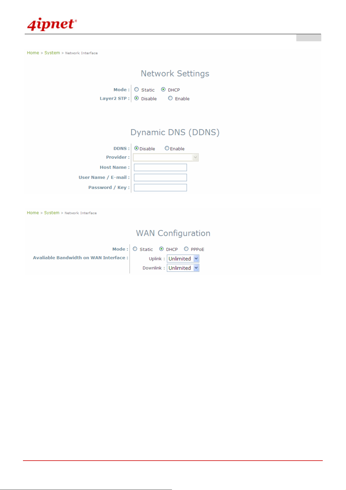
4.1.2 Network Interface
There are 3 connection types supported on OWL800’s WAN port: Static, DHCP or PPPoE.
AP Mode
© 2008 4IPNET, INC.
27

User’s Manual
OWL800 / OWL2000 / HSG800 ENGLISH
Gateway Mode
© 2008 4IPNET, INC.
28

User’s Manual
OWL800 / OWL2000 / HSG800 ENGLISH
Mode: Determine the way to obtain the IP address, by DHCP or Static.
o Static setting: Static setting is to set these parameters manually. Basic parameters such as IP
address, subnet mask, and gateway are needed.
AP Mode
Gateway Mode
o DHCP client: This option is provided when the users have a DHCP in the wired network, and make
sure the network connection is correct.
© 2008 4IPNET, INC.
29
User’s Manual
OWL800 / OWL2000 / HSG800 ENGLISH
AP Mode
Gateway Mode
o PPPOE: When selecting PPPoE to connect to the network, please set the “Username”,
“Password”, “MTU” and “CLAMP MSS”. There is a Dial on demand function under PPPoE. If
this function is enabled, a Maximum Idle Time can be set. When the idle time is reached, the
system will automatically disconnect itself.
© 2008 4IPNET, INC.
30

User’s Manual
OWL800 / OWL2000 / HSG800 ENGLISH
Gateway Mode
Primary and Alternate DNS Server: If any other hosts address of management service are given in FQDN
format (Full qualified domain name), ensure at least one of these DNS (Domain Name Service) server’s IP is
correct.
Layer 2 STP: It depends on the configuration of the OWL800 including wired and wireless settings. When it is
configured to bridge several networks, STP needs to be enabled.
Dynamic DNS (DDNS): OWL800 provides a convenient DNS function to translate a domain name to the IP
address of WAN port that helps the administrator memorize and connect to WAN port. If the DHCP is activated
at WAN port, this function will also update the newest IP address regularly to the DNS server.
© 2008 4IPNET, INC.
31
User’s Manual
OWL800 / OWL2000 / HSG800 ENGLISH
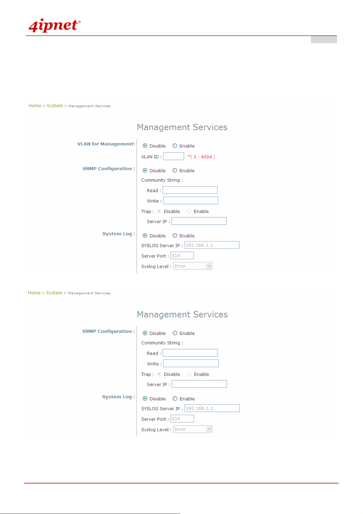
4.1.3 Management
For easier maintenance, SNMP (Simple Network Management Prot ocol) and remote Syslog se rvices are provided in
OWL800. The OWL800 will be managed remotely in a centralized manner.
AP Mode
Gateway Mode
© 2008 4IPNET, INC.
32

User’s Manual
OWL800 / OWL2000 / HSG800 ENGLISH
SNMP Configuration: By enabling this SNMP service, the remote SNMP manager could obtain OWL800's
system status.
o Community String: Specify the password for Read and Write.
o Read: This string is for the SNMP managers to get the MIB information from the system. The
example here indicates that the SNMP managers can read the MIB information from the system
when the SNMP mangers use the community Public.
o Write: This string is for the SNMP managers to set the MIB information to the system. The example
here indicates that the SNMP managers can write the MIB information to the system when the
SNMP mangers use the community Private.
o Trap: Enable or Disable the feature. When enabled, its reported event will be sent to assigned
management station with specified Server IP Address.
Syslog Configuration: By enabling this service, specify a remote Syslog server which could accept system log
messages from OWL800 remotely. By reading the Syslog message in the remote server, review activities of all
installed OWL800s in the network.
o Server Port: Port of the server.
o Log Level: Select desired level of received events.
© 2008 4IPNET, INC.
33
User’s Manual
OWL800 / OWL2000 / HSG800 ENGLISH
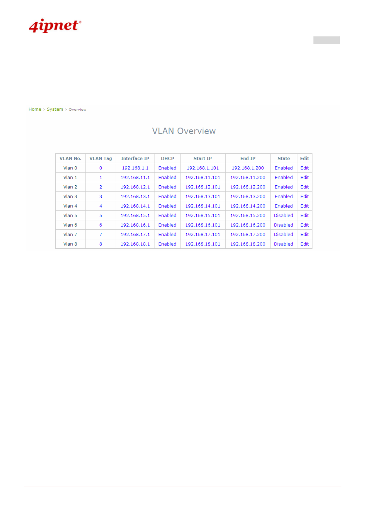
4.1.4 VLAN Overview
VLAN is to separate one physical network into different logical zones. VLAN overview is a summary table tells you
each VLAN’s current status. There are up to 9 tab-based VLANS to enable. Each VLAN is associated to one policy;
authentication methods, encryption methods, traffic control, DHCP and etc.
Gateway Mode
VLAN Tag: The VLAN tag for the respective VLAN. The hyperlink connects to VLAN’s Configuration Zone.
Interface IP: The hyperlink connects to VLAN’ s Configuration Zone.
DHCP: Enable or Disable DHCP st ate shown here. The hyperlink connects to VLAN’s Configuration Zone.
Start IP: Show the Start IP Address here. The hyperlink connects to VLAN’s Configuration Zone.
End IP: Show the End IP Address here. The hyperlink connects to VLAN’s Configuration Zone.
State: Enable or Disable VLAN state shown here. The hyperlink connects to VLAN’s Configuration Zone.
Edit: Click “Edit” hyperlink takes you to each VLAN’s Configuration Zone.
© 2008 4IPNET, INC.
34

User’s Manual
OWL800 / OWL2000 / HSG800 ENGLISH
Gateway Mode >> VLAN Configuration
© 2008 4IPNET, INC.
35

User’s Manual
4.1.5 VLAN Configuration
OWL800 / OWL2000 / HSG800 ENGLISH
Gateway Mode
VLAN: This section is where to configure each VLAN. There are 9 VLANs (VLAN0~8).
Remark: Text remark about this VLAN.
VLAN T ag: each VLAN is identified by di fferent t ags carried withi n message frames. The num ber that is mapped
to the selected VLAN.
© 2008 4IPNET, INC.
36

User’s Manual
Operating Mode:
o NA T: NAT stands for Network Address Translation that hides internal IP addresses. Like a two-way
mirror (transparent mirror), NAT is like a protective wall that packets inside can pass through this
wall and being transferred to the outside, but the outside ca n only see the IP Address of “the wall”.
o Router: Router mode is used when LAN client IPs are meant to be visible to WAN side for example
if clients hold real IPs.
Network Interface: IP address and Subnet Mask of this VLAN.
DHCP Server:
o Enable DHCP: Make OWL800 your DHCP server.
OWL800 / OWL2000 / HSG800 ENGLISH
o Domain Name: Domain Name looks like “domain.com” that is a better memorable term to IP
address. Client looks up a website by entering its domain name or its IP address.
o WINS Server: WINS is short for windows internet name. WINS server translates Windo ws
computer names to IP addresses. To see the full computer name: right click “My Computer” icon
and scroll down to “Properties”.
o Lease Time: A Lease Time is the time period that DHCP server permits DHCP client to use a
particular IP address. Shorter lease time is set for clients with the higher mobility. For example,
clients in a commercial fair, exhibition, or around a hotel hotspot, come to this service zone for a
quick internet surf and leave.
o Disable DHCP: Disable OWL800’s DHCP function.
© 2008 4IPNET, INC.
37

User’s Manual
OWL800 / OWL2000 / HSG800 ENGLISH
Reserved IP Address list: Reserved IP Address is a static IP add ress reserved for a special client by his M AC
address.
Allowed Authentication Method and Applied Policy:
o Local: Select a policy and apply to local authentication.
o External RADIUS server: Select a policy and apply to RADIUS authentication.
© 2008 4IPNET, INC.
38
User’s Manual
OWL800 / OWL2000 / HSG800 ENGLISH
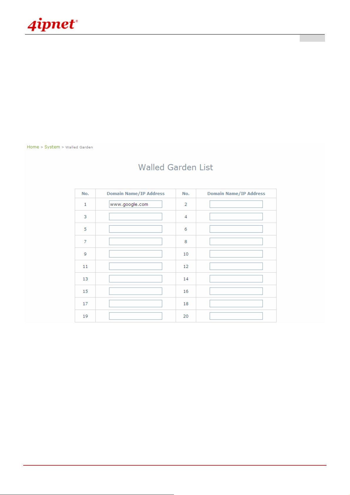
4.1.6 Walled Garden
The Walled Garden supported by the system provides free surfing areas for clients to access before they are
authenticated by the system. IP addresses or domain names of the websites can be defined in this list. Clients
without network access right can still have a chance to experience the actual network service free of charge. This
function allows clients to access specified websites before login and authentication. An example may be seen in
hotels, where guests without network access right are allowed to utilize the network service free of charge such as
accessing the Hotel’s homepage. Up to 20 addresses or domain names of the websites can be defined in this list.
Users without the network access right can make use of the actual network service free of charge.
Gateway Mode
Walled Garden List is a list of websites for all use r s to access before login or without being authenticated. Enter the
IP Address or Domain Name of those websites and click Apply.
portal page, commercial advertisement, and etc.
These websites can be for example menu,
© 2008 4IPNET, INC.
39

User’s Manual
OWL800 / OWL2000 / HSG800 ENGLISH
© 2008 4IPNET, INC.
40
User’s Manual
OWL800 / OWL2000 / HSG800 ENGLISH
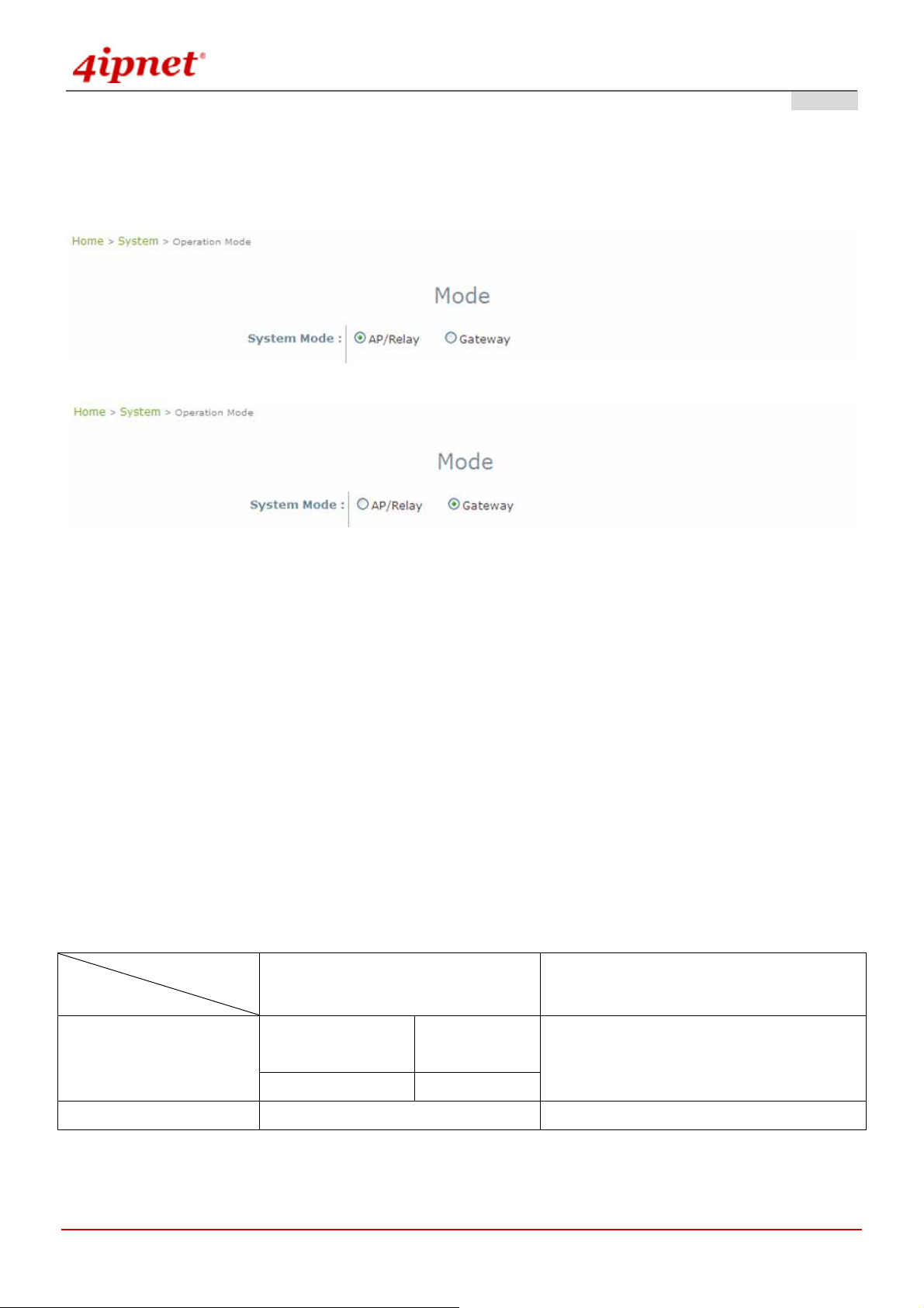
4.1.7 Mode
OWL800 supports 4 Radio modules; RF1 and RF2 are included in the original package. RF3 and RF4 are optional.
From the software perspective, there are modes of two layers; “System Mode” and “Radio module Mode”.
AP Mode
Gateway Mode
System Mode:
o AP/Relay Mode: Switching between AP mode and Relay mode is only for RF1.
AP Mode: RF1 acts like a regular Access Point’ Radio module for other wireless clients to
associate.
Relay Mode: Relay Mode is to create WDS link with other wireless devices.
o Gateway Mode: Selecting Gateway Mode enhances OWL800 a n ew feature – user authentication
gateway. Please see “Users” for configuration instruction.
Radio module Mode:
o AP mode: RF1 acts like a regular Access Point’ Radio module for other wireless clients to
associate.
o WDS mode: WDS mode is for Radio modules to create WDS link with other wireless devices.
o Scan mode: Scan mode is for system to search for available wireless devices.
Table for Radio modules and Modes supported:
System Mode
Radio module Mode
AP / Relay Mode Gateway Mode
RF1
RF2
If select “AP”
If select “WDS” Relay mode
WDS mode / Scan mode WDS mode / Scan mode
AP mode
(Default)
AP mode or WDS mode
© 2008 4IPNET, INC.
41

User’s Manual
OWL800 / OWL2000 / HSG800 ENGLISH
4.2 AP
This section provides information on the following functions: VPA Overview, General Settings, VAP
Configuration, Security Settings, Advanced Wireless Settings and Access Control Settings. The OWL800
supports up to 8 WLANs by Virtual Access Point (V AP). Each VAP can have its own settings including ESSID,
VLAN ID, security settings, and etc. Therefore, these VAPs can bring different service level to clients depending on
the ESSID connected to. Please click on the menu item AP to configure VAPs.
4.2.1 Overview
The overall status is collected in this page, including enable/disable state, security type, MAC state, and advance d
settings. OWL800 has 8 VAPs; each has its own settings. In the table, please click on each setting item to have
detailed configuration of these VAPs respectively.
Gateway & AP Mode
© 2008 4IPNET, INC.
42

User’s Manual
OWL800 / OWL2000 / HSG800 ENGLISH
State: The hyperlink showing enable or disable connects to the screen of VAP Configuration.
Gateway & AP Mode
Security Type: The hyperlink showing security type connects to the scree n of Security Settings.
Gateway & AP Mode
MAC ACL: The hyperlink showing status of MAC ACL connects to the screen of Access Control Settings.
Gateway & AP Mode
Advanced Settings: The hyperlink of advanced settings connects to the screen of Adv anced Wireless
Settings.
© 2008 4IPNET, INC.
43

User’s Manual
OWL800 / OWL2000 / HSG800 ENGLISH
Gateway & AP Mode
© 2008 4IPNET, INC.
44

User’s Manual
OWL800 / OWL2000 / HSG800 ENGLISH
4.2.2 General
Gateway & AP Mode
Band: The operating wireless frequency band of the device’s AP module. Choose among frequency band
Disable, 802.11b, 802.11g or mixed mode 802.11b+802.11g. (Note: 802.11 a band is only allowed for the
second radio, which serves as WDS for bridge/backhaul.)
Short Preamble: Enable for using Short Preamble and disable for using the Long Preamble option.
Channel: Choose from channel 1 ~ 11 in b/g mode, depending on the region or auto.
Max Transmit Rate: Choose transmit rate from the drop-down list. The maximum transmit rate can be set as
“auto” or specific available rate.
Transmit Power: Choose from Lowest Power to Highest Powe r level or auto. (Note: The factory default
setting is Highest ( ~ <19 dBm). Each level steps down around 3 dBm. That is, even the transmit power is
adjustable; it can only be adjusted down from the radio card’s limit. There is no power buster inside the
product.)
Note: Depending on the region (US, EU, or JP) the product is built for shipping to, the number of selectabl e
channels varies. For example, there are only 11 channels selectable in 2.4G band for the product s made to ship to
the US market, and there are 13 channels selectable in 2.4G for the product m ade to ship to the EU m arket. There
are different firmware versions with different selectable channel-lists for different regions.
© 2008 4IPNET, INC.
45
User’s Manual
OWL800 / OWL2000 / HSG800 ENGLISH
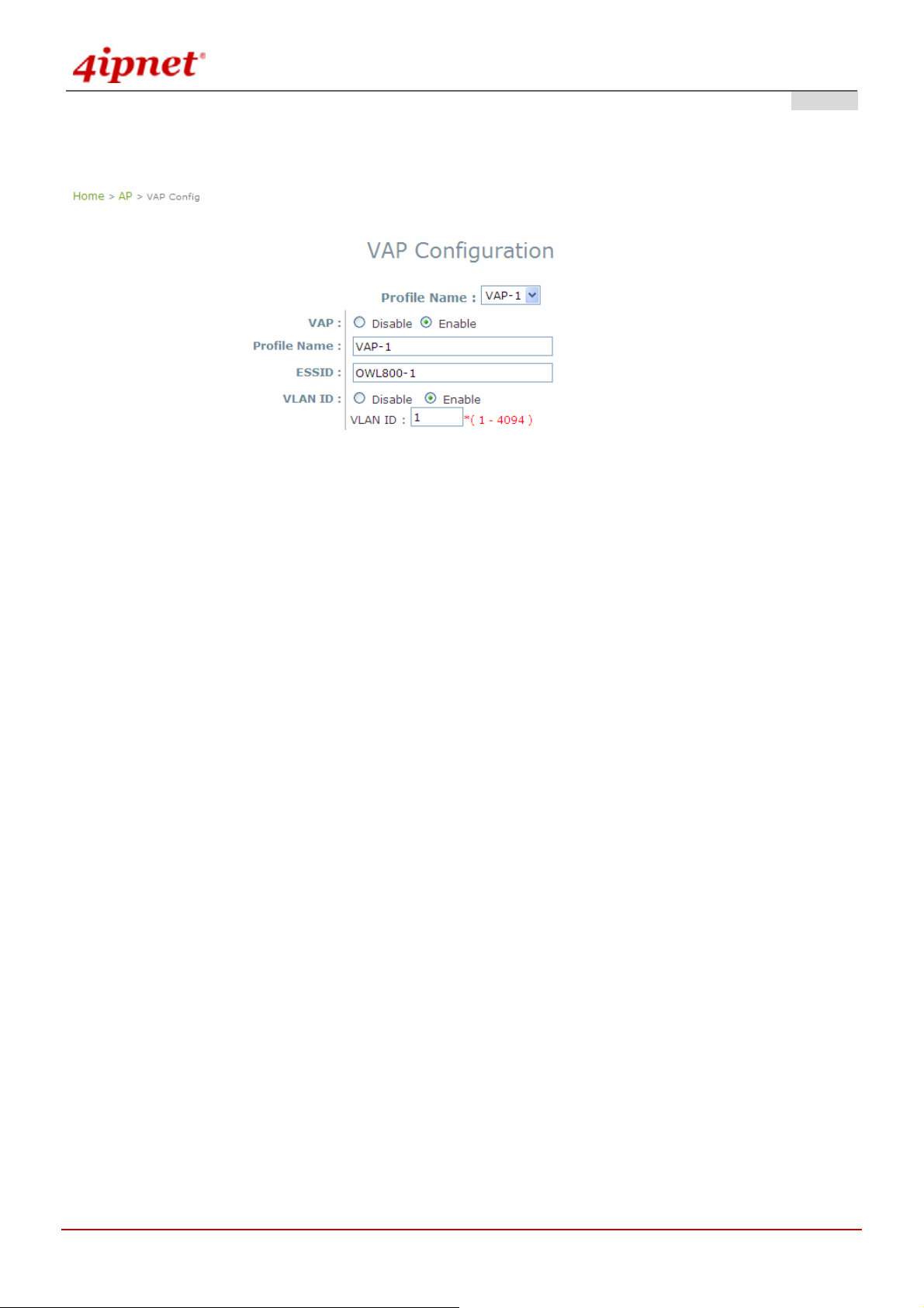
4.2.3 VAP Configuration
Gateway & AP Mode
To enable each VAP in the OWL800, the administrat or has to conf igure each VAP individual manually. The settings
of each VAP are collected as its profile.
VAP: Enable or disabled virtual AP settings.
Profile Name: Give the profile an identity for management purpose.
ESSID: Extended Service Setting ID, indicate the SSID which the clients used to connect to the VAP. ESSID
will determine the service type of a client which assigned to the specified VAP.
VLAN ID: Virtual LAN, the OWL800 support s tagged VLAN. To enable VLAN function, each VAP needs a
unique VLAN ID; valid values are from 1 to 4094.
© 2008 4IPNET, INC.
46

User’s Manual
OWL800 / OWL2000 / HSG800 ENGLISH
4.2.4 Security
The OWL800 supports various user authentication and data encryption in each VAP's profile. Thus the
administrators can depend on the need to provide different service levels to clients. The security type includes the
items on the drop-down menu of security type:
None: No authentication required. This is the default setting as shown in the figure.
Gateway & AP Mode
WEP: Supports key length of 64/128/152 bits.
o WEP Key Format: Diff erent format will affect the number of inputs to WEP keys.
Gateway & AP Mode
© 2008 4IPNET, INC.
47

User’s Manual
802.1x: Provides RADIUS authentication and enhanced WEP.
Gateway Mode
OWL800 / OWL2000 / HSG800 ENGLISH
AP Mode
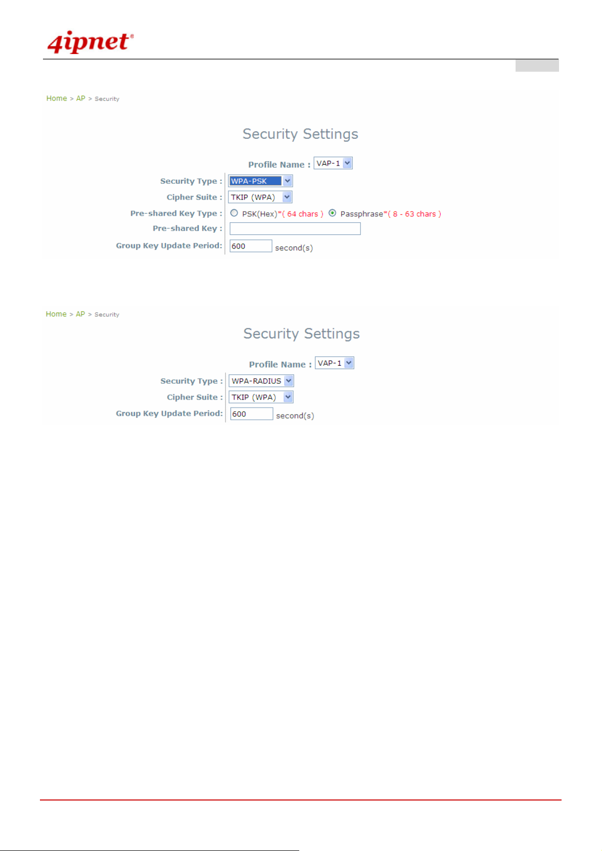
WPA-PSK: Provides shared key authentication in WPA data encryption.
© 2008 4IPNET, INC.
48
User’s Manual
OWL800 / OWL2000 / HSG800 ENGLISH
Gateway & AP Mode
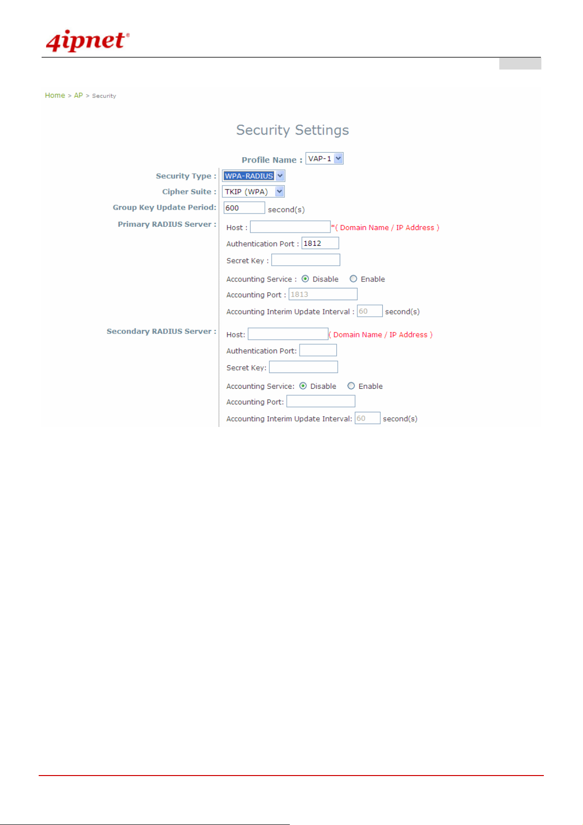
WPA-RADIUS: Authenticate user by RADIUS in WPA data encryption.
Gateway Mode
© 2008 4IPNET, INC.
49
User’s Manual
OWL800 / OWL2000 / HSG800 ENGLISH
AP Mode
© 2008 4IPNET, INC.
50

User’s Manual
OWL800 / OWL2000 / HSG800 ENGLISH
4.2.5 Advanced
Virtual AP advanced settings should mostly meet general requirements. Take the following parameters for the
purpose if occasionally it is necessary to tune or debug the wireless network.
Gateway & AP Mode
Beacon Interval: This interval specifies the time interval, in milliseconds. Between each beacon frame is
transmitted.
RTS Threshold: To control station access to medium and to alleviate this effect of the hidden terminal problem,
we can tune this RTS threshold value. It should have a value among 1-2346 and is default to 2346.
Fragmentation Threshold: A unicast frame larger than this threshold will be fragmented before the
transmission. If significant numbers of collisions are occurring, we can try to take a smaller value of the
fragmentation threshold to see if it helps.
Broadcast SSID: Disable this item will prevent the OWL800 from broadcasting its SSID publicly.
Wireless Station Isolation: By enabling this item, all station s in the same OWL800's coverage area can only
communicate with the OWL800 only.
WMM: To decide which data streams are most important and assign them a highe r traffic priority, we may
enable this feature. It is default disabled.
IAPP: To provide a better roaming capability for the stations among APs nearby the OWL800, we can enable
this item. Its default disabled.
© 2008 4IPNET, INC.
51

User’s Manual
OWL800 / OWL2000 / HSG800 ENGLISH
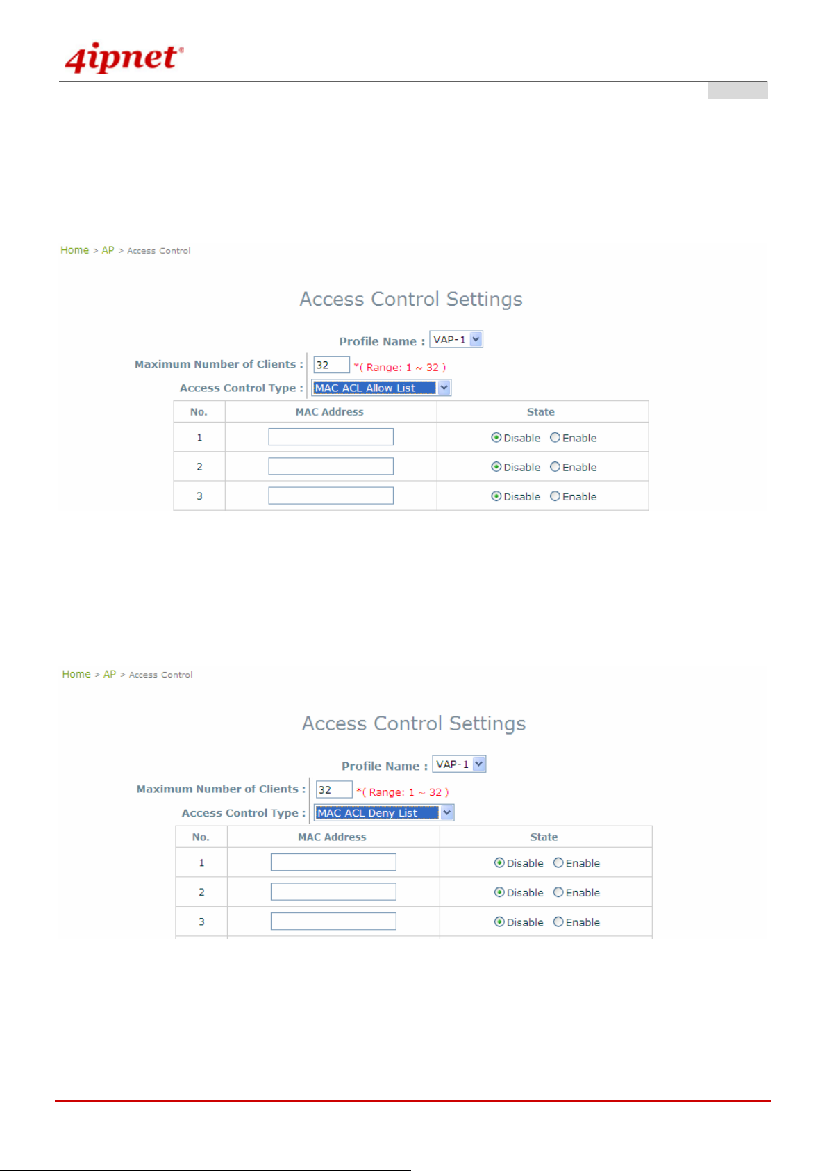
4.2.6 Access Control
The OWL800 supports various methods of authenticate clients from using wireless LAN. The default policy is
unlimited connections without any authentication required. To restrict the station number of wireless connecti ons,
just change the Maximum number of stations to a desired number. For example, while the number of station is
set to 20, only 20 stations are allowed to connect to this VAP.
For MAC ACL control, the supported methods include:
Disable Access Control: No MAC address check required
MAC ACL Allow List: Deny all except allowed ones in the list
MAC ACL Deny List: Allow all except denied ones in the list
The one selected in the Access Control Type is the activated policy while the rest of the options are inactive.
Disable Access Control
No MAC address check required.
Gateway & AP Mode
© 2008 4IPNET, INC.
52
User’s Manual
OWL800 / OWL2000 / HSG800 ENGLISH
MAC ACL Allow List
When the policy is set to Allow List, all wireless connection to the V A P will be denied except for those allowed
MAC addresses listed. For each allowed MAC address, the administrator can still enabl e or disabled the rule
applied to the specified one. For example, 11:22:33:44:55:66 is in the allow list, to temporarily deny its access, we
can disable the rule on it.
Gateway & AP Mode
MAC ACL Deny List
When the policy is set to Deny List, all wireless connection to the VAP will be allowed except those denied MAC
addresses listed. When the users want to allow one listed MAC address temporary, disable the address from the
deny lists.
Gateway & AP Mode
© 2008 4IPNET, INC.
53
User’s Manual
OWL800 / OWL2000 / HSG800 ENGLISH
4.3 WDS
OWL800 has equipped with Wireless Distributio n System interfaces, and each i nterface can est ablish up t o 4 WDS
links to other WDS peers. In WDS configuration, each WDS-link setting is collected into one profile. This section
provides information in the following functions: WDS Link Overview, WDS Interface Settings, WDS Link
Settings, and WDS Discovery. The configurations under this category apply to all Virtual Access Point in this
device.
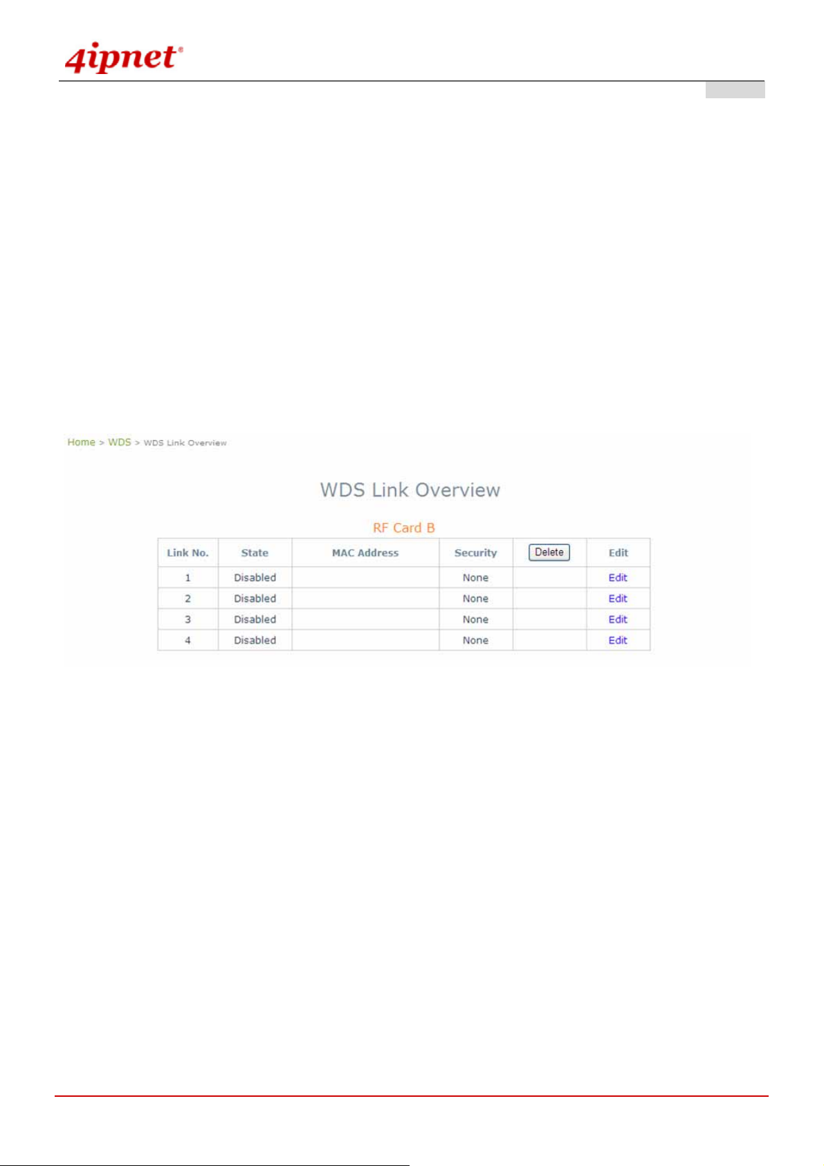
4.3.1 Overview
WDS links are used as backhaul or bridges. The figure provides an overall status of all WDS links. Turn the WDS
link by giving signal quality in the table.
Gateway & AP Mode
Link No.: corresponding profiles of each WDS interface
State: Enabled or Disabled the plan.
MAC Address: remote peer's MAC address.
Security: Choose between Disable security and WEP type of security.
Delete: Remove profiles by checkbox selection and click on Delete to remove them.
Edit: To change the individual setting of each WDS profile, click on Edit to modify the settings. The hyperlink
connects to the screen of WDS Configuration.
© 2008 4IPNET, INC.
54

4.3.2 General
User’s Manual
OWL800 / OWL2000 / HSG800 ENGLISH
Gateway & AP Mode
The shared secret is used to discover remote WDS peer . Both end s mu st share the same key; otherwise the
remote peer will ignore the request. To use WDS discovery, both ends must equipped with this feature containing
shared secret. For example, the remote one is also an OWL800.
Each WDS interface has its own RF (Radio Frequency) settings; normally, valid combination of RF parameters
configuration would like the following table. However, the available values of each item will be affected by the RF
regulation which is configured in AP's RF settings.
¾ Band: Select appropriate wireless band or disable if the service is not required; bands available for WDS
links are 802.11a, 802.11b, 802.11g and 802.11b+802.11g.
Note: The second radio in the system is designed for building WDS links. WDS links are used as backhaul or
point-to-point bridges. WDS links do not service AP clients. 11a (5.725~5.85GHz) is used by the 2nd radio module
typically in order to avoid the channels of 11b/g (2.4GHz) used by the first radio module for serving clients.
However, 11b and 11g are still available to the 2nd radio (WDS) in case the administrator determines to use 11b/g
for building WDS links base on their deployment condition.
¾ Channel: Select an appropriate channel from the list to correspond with the network settings.
Note: Depending on the region (US, EU, or JP) the product is built for shipping to, the number of selectabl e
channels varies. For example, there are only 11 channels selectable in 2.4G band for the product s made to ship to
the US market, and there are 13 channels selectable in 2.4G for the product m ade to ship to the EU m arket. There
are different firmware versions with different selectable channel-lists for different regions.
© 2008 4IPNET, INC.
55

User’s Manual
OWL800 / OWL2000 / HSG800 ENGLISH
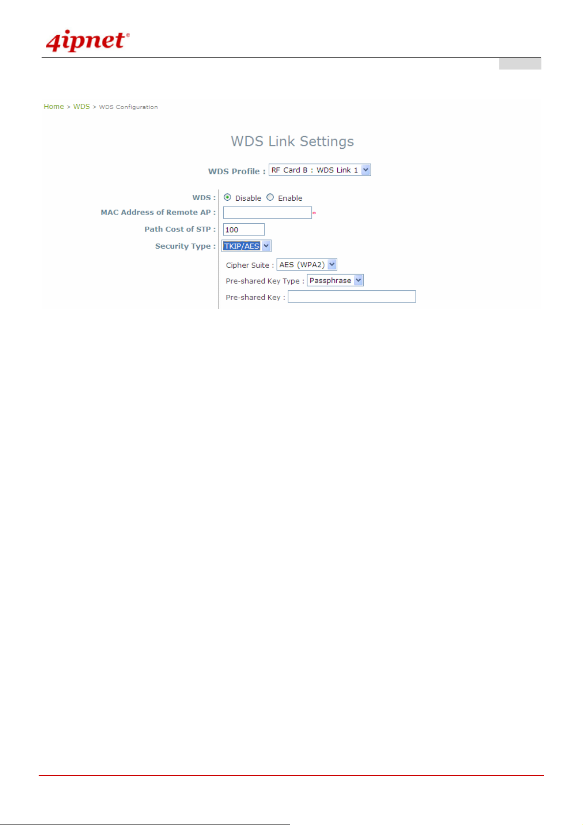
4.3.3 WDS Configuration
For each WDS link profile, the administrators need to remote peer's MAC address and the authentication method for
establishing connection to the peer.
Gateway & AP Mode
WDS Profile: Total 8 profiles included in the OWL800 device, pull the drop-down menu to select one WDS
profile to configure.
WDS: Enable or Disable the specified WDS link.
MAC Address of Remote AP: For each link, type the MAC address of the remote peer here. The MAC address
may also get by WDS Discovery. Please refer to WDS discovery in the following section for detail.
Path Cost of STP: An assigned weighted metric here will determine the best path for data flow.
Security Type: Set the encryption (WEP or None) of WDS link here.
o None: No authentication is required to establish this WDS link.
o WEP: Establish the WDS link in WEP authenticatio n which must provides key length, format an d the
key itself respectively, recommended.
Gateway & AP Mode
© 2008 4IPNET, INC.
56
User’s Manual
OWL800 / OWL2000 / HSG800 ENGLISH
o TKIP:
Gateway & AP Mode
© 2008 4IPNET, INC.
57
User’s Manual
OWL800 / OWL2000 / HSG800 ENGLISH
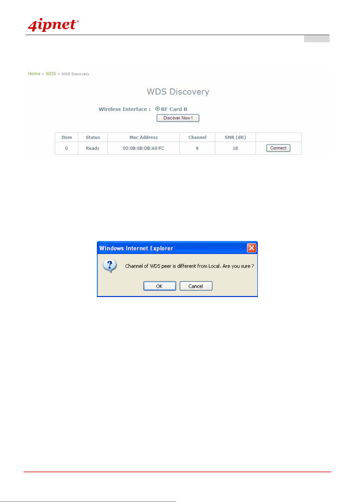
4.3.4 WDS Discovery
Gateway & AP Mode
OWL800 provides easy-to-use peer discovery feature, the WDS discovery, which both ends must have the same
'shared secret'. Please refer to WDS RF settings for the shared secret. The remote peer must also have the sam e
'Scan' feature equipped. To start WDS discovery, select WDS interface and then click on the Discover Now button.
If the local WDS is in remote peer's coverage area, the information of remote peer will be listed. Click on the
Connect button, the MAC address of remote peer will be retrieved locally for WDS connection.
© 2008 4IPNET, INC.
58

User’s Manual
OWL800 / OWL2000 / HSG800 ENGLISH
4.4 User
When set to Gateway Mode, OWL800 is capable of dealing with user authentication, authorization and accounting.
The user account information is stored in the local database or a specified external RADIUS serve r. This section
provides information on the following functions: Local User Authentication, RADIUS Authentication, On-demand
Authentication, Policy Configuration, Policy Firewall, Policy Specific Route, and Roaming Out and 802.1X
Client Device Settings.
4.4.1 Local
Local user database is built locally in OWL800. To add new user accounts, enter specific information (User Name,
Password, MAC Address, and Remark) and click Add. All created accounts are displayed in the User List.
Gateway Mode
Postfix: It is a string used by the system to distinguish which database/server will be used for authentication
when a user enters the user name to log in. For example, when the Postfix is configured a s “local”, user1 @local
will tell the system to use Local user database. A meaningful string will help administrators manage the
authentication. It is only allowed to use numbers (0 to 9), alphabets (a to z or A to Z), dash (-), underline (_) and
dot (.) with a maximum of 40 characters.
© 2008 4IPNET, INC.
59

User’s Manual
OWL800 / OWL2000 / HSG800 ENGLISH
Multiple Login: When enabled, the same Local user account can be used for login by multiple users at the
same time.
802.1X Authentication: When enabled, Local user database will be used as internal RADIUS database for
802.1X-enabled LAN devices, such as AP and switch. For more information, please see Appendix B. 802.1X
Support.
Account Roaming Out: When enabled, Local user database functions as an external RADIUS serve r for
another gateway. Therefore, a user can roam out to the network under anther gateway by using the same Local
account. For more information, please see Appendix B. 802.1X Support. The button Roaming Out & 802.1X
Client Device Settings connects to the screen of 802.1X.
Gateway Mode >> Add Roaming Out and 802.1X list
Import/Export Local User: The button Import/Export Local User connects to the screen of Import & Export
User.
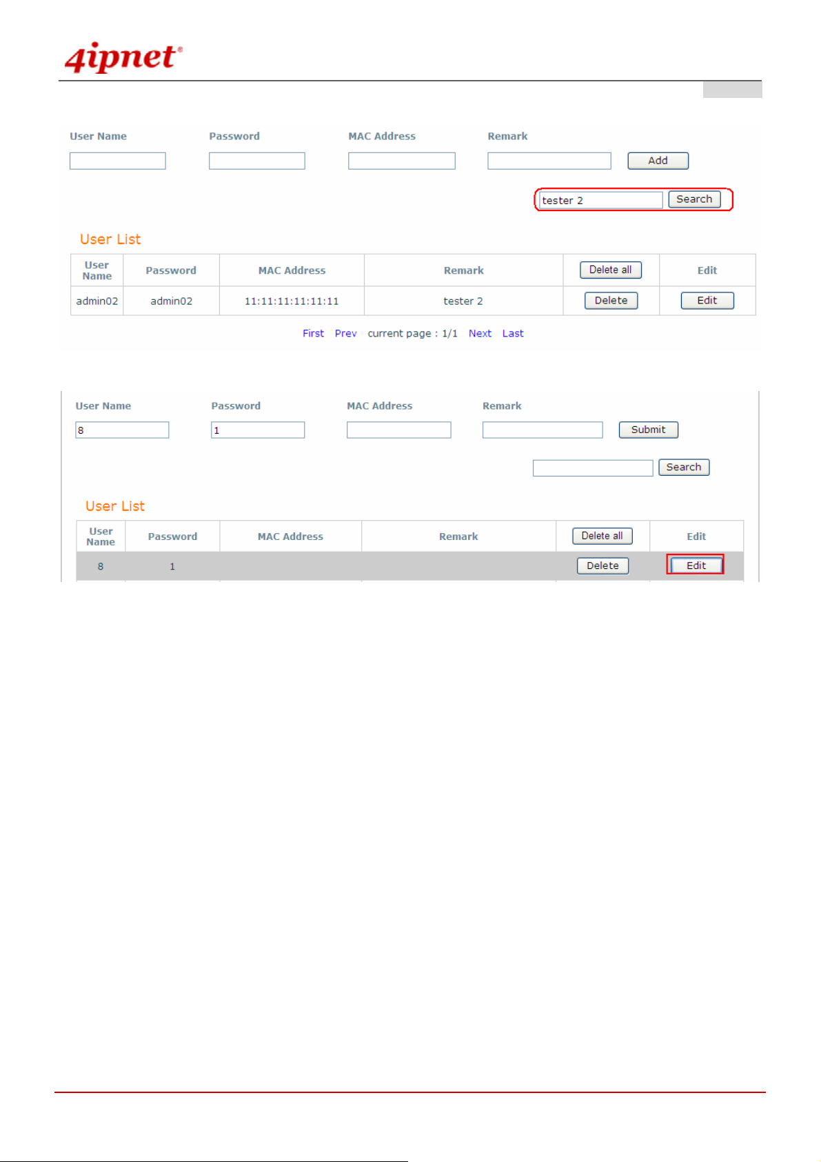
User List: When click Edit, change the content of User Name, Password, Mac Address and Remark above
the List.
Gateway Mode >> Add User List
© 2008 4IPNET, INC.
60
User’s Manual
OWL800 / OWL2000 / HSG800 ENGLISH
Gateway Mode >> Search User List
Gateway Mode >> Edit User List
© 2008 4IPNET, INC.
61

User’s Manual
OWL800 / OWL2000 / HSG800 ENGLISH
4.4.2 RADIUS
The system supports user authentication against external RADIUS servers. It functions as a RADIUS authenticator
for external RADIUS servers.
To enable the RADIUS authentication, enter the related information for the primary RADIUS server and/or the
secondary RADIUS server (not required). These settings will be ef fective immediately af ter clicking the Apply button.
Gateway Mode
© 2008 4IPNET, INC.
62

User’s Manual
OWL800 / OWL2000 / HSG800 ENGLISH
Postfix: It is a string used by the system to distinguish which database/server will be used for authentication
when a user enters the user name to log in. For example, when the Postfix is configured as “radius1”,
user1@radius1 will tell the system to use this RADIUS server. A meaningful string will help administrators
manage the authentication. It is only allowed to use numbers (0 to 9), alphabets (a to z or A to Z), dash (-),
underline (_) and dot (.) with a maximum of 40 characters.
Extensible Authentication Protocol: When enabled, the system can accept 802.1X authentication request
(EAP request) from 802.1X capable device s and relay the request to external RADIUS server. For more
information, please see Appendix B. 802.1X Support.
802.1X Client Device Settings: When Extensible Authentication Protocol is enabled, by clicking on this
button, administrators can go to Roaming Out and 802.1X Client Device Settings page to further set up the
802.1X capable devices that are allowed to authenticate against the Local user database.
Username Format to RADIUS Server: When ID Only is selected, only the username will be sent to the
external RADIUS server for authentication. On the other hand, when Complete option is selected, both the
username and the postfix will be sent to the RADIUS server.
Primary RADIUS Server & Secondary RADIUS Server:
Host: Domain name or IP address of the external RADIUS server.
Authentication Port: Port number of the external RADIUS server for authentication.
Security Key: The Secret Key for RADIUS authentication.
Accounting Service: RADIUS accounting can be enabled or disabled.
Accounting Port: Port number of the external RADIUS server for accounting.
Authentication Protocol: The authentication protocol configurations of the system must match with the
configurations of the remote RADIUS server. PAP (Password Authentication Protocol) transmits password in
plain text without encryption. CHAP (Challenge Handshake Authentication Protocol) is a more secured
authentication protocol with hash encryption.
© 2008 4IPNET, INC.
63

User’s Manual
OWL800 / OWL2000 / HSG800 ENGLISH
4.4.3 On-demand
There are some deployment scenarios (for example, at venues such as coffee shops, hotels, restaurants, etc.)
where retail customers or casual visitors want to get wireless Internet acce s s. To offer the Wi-Fi access (either for
commercial use or for free), user accounts should be able to be created upon reque st and account tickets/receipts
should also be provided. Therefore, On-demand is designed as the authentication option for this type of deployment
scenarios.
Gateway Mode
Postfix: It is a string used by the system to distinguish which database/server will be used for authentication
when a user enters the user name to log in. For example, when the Postfix is configured as “ondeman d”,
xrf6@ondemand will tell the system to use this authentication database. A meaningful string will help
administrators manage the authentication. It is only allowed to use numbers (0 to 9), al pha bets (a to z or A to Z),
dash (-), underline (_) and dot (.) with a maximum of 40 characters.
Ticket Customization: On-demand account ticket can be customized here.
Gateway Mode
© 2008 4IPNET, INC.
64
User’s Manual
OWL800 / OWL2000 / HSG800 ENGLISH
o Receipt Header: There are two receipt headers supported by the system. The entered content will be
printed on the receipt. These headers are optional.
o SSID: The administrator can enter the defined wireless SSID in this field and it will be printed on the
receipt for guest users’ reference when accessing the Internet via wireless LA N service. The SSIDs given
here should be those of the service zones enabled for guest users.
o Wireless Key: The administrator can enter the defined wireless key such as WEP or WPA in the field.
The Wireless Key will be printed on the receipt for the guest users’ reference when accessing the Internet
via wireless LAN service.
o Remark: The administrator can enter extra information in this field for remark.
o Receipt Footer: The entered content will be printed on the receipt. This footer is optional.
Currency: The desired monetary unit or a unit specified by administrators for billing purpose.
Number of Tickets: Print one or dupli c ate receipts, when pressing the print button of the ticket printer which
connected to serial port.
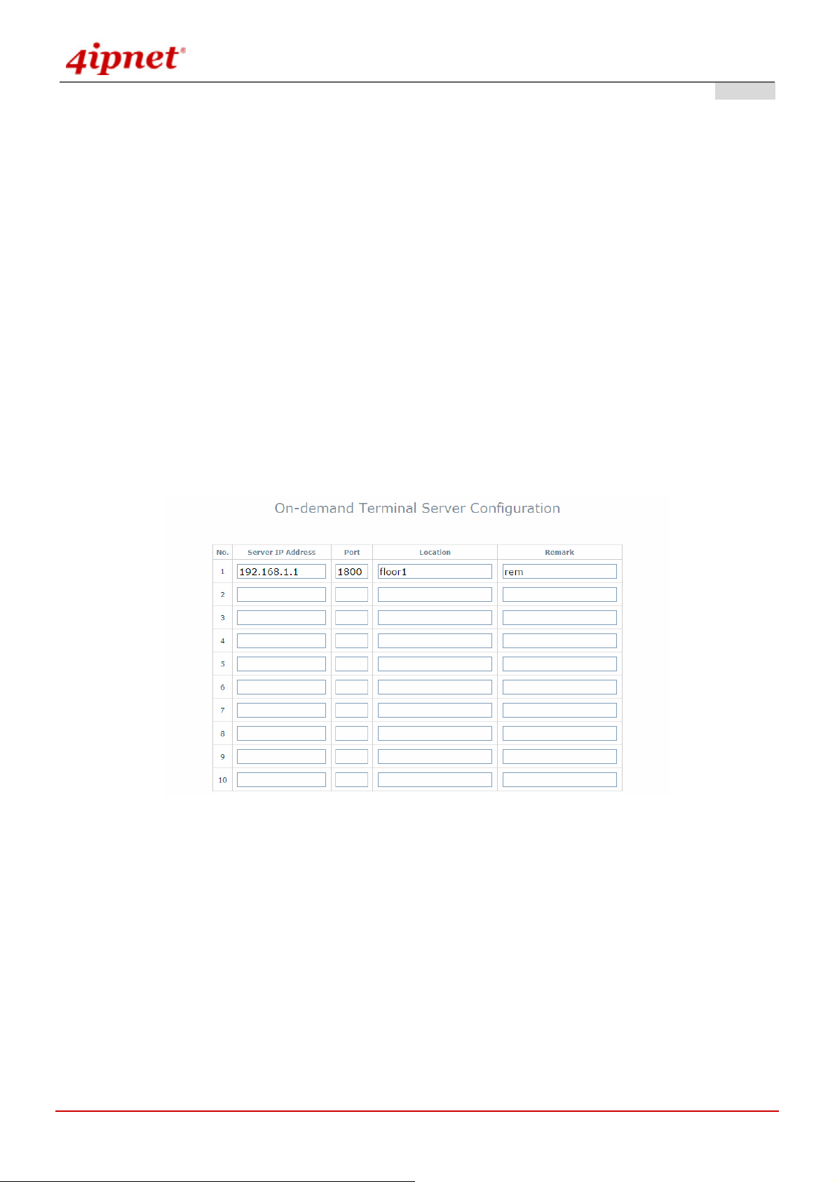
Terminal Servers:
Gateway Mode
© 2008 4IPNET, INC.
65
User’s Manual
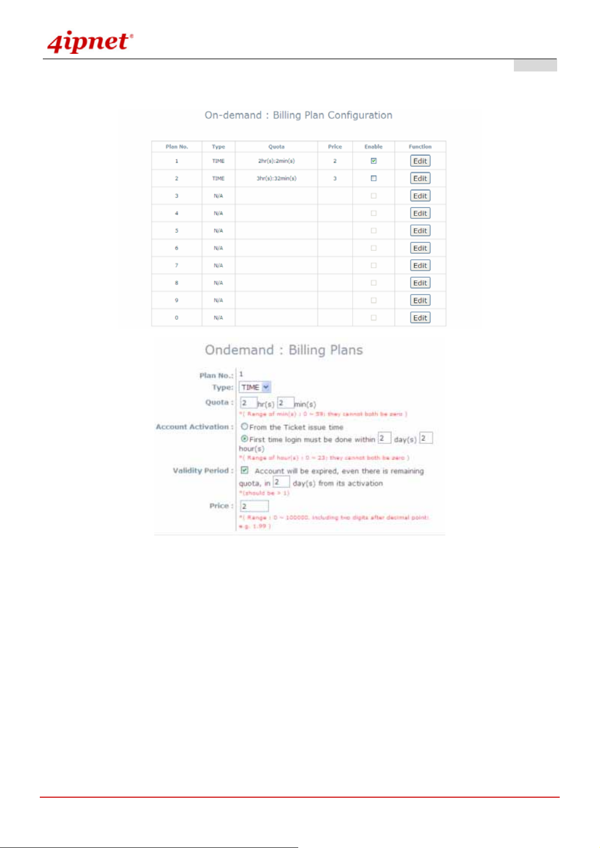
Billing Plans: Administrators can configure several billing plans.
OWL800 / OWL2000 / HSG800 ENGLISH
Gateway Mode
© 2008 4IPNET, INC.
66

User’s Manual
OWL800 / OWL2000 / HSG800 ENGLISH
On-demand Account Creation: When at least one plan is enabled, the administrator can generate On-demand
user accounts here.
Gateway Mode
On-demand Account List: All created On-demand accounts are listed and related information on is also
provided.
Gateway Mode
© 2008 4IPNET, INC.
67

User’s Manual
OWL800 / OWL2000 / HSG800 ENGLISH
¾ Search: Enter a keyword of a username to be searched in the text filed and click this
button to perform the search. All usernames matching the keyword will be listed.
¾ Username: The login name of the instant account.
¾ Password: The login password of the instant account.
¾ Remaining Quota: The total time that the user can use currently.
¾ Status: The status of the account.
¾ Delete All: This will delete all the users at once.
¾ Delete: This will delete the users individually.
© 2008 4IPNET, INC.
68
User’s Manual
OWL800 / OWL2000 / HSG800 ENGLISH
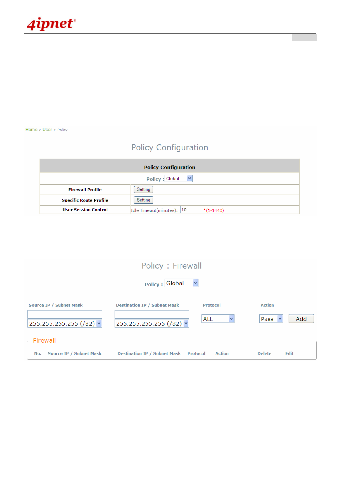
4.4.4 Policy
The system supports multiple control Policies, including the Global Policy and individual Policy (1 ~ 16). Each
Policy consists of access control profiles that can be configured respectively and applied to users.
Global Policy:
Global is the system’s universal policy including Fire wall Rules, S pecific Routes Profile whi ch will be applied to all
users unless the user has been regulated and applied to another policy.
Gateway Mode >> Global Policy
Firewall Profile: Global policy and each policy have a firewall service list and a set of firewall profile which is
composed of firewall rules.
Specific Route Profile: The default gateway of WAN1, WAN2, or a desired IP address can be defined in a
policy. When Specific Default Route is enabled, all clients applied this policy will access the Internet through
this default gateway.
© 2008 4IPNET, INC.
69
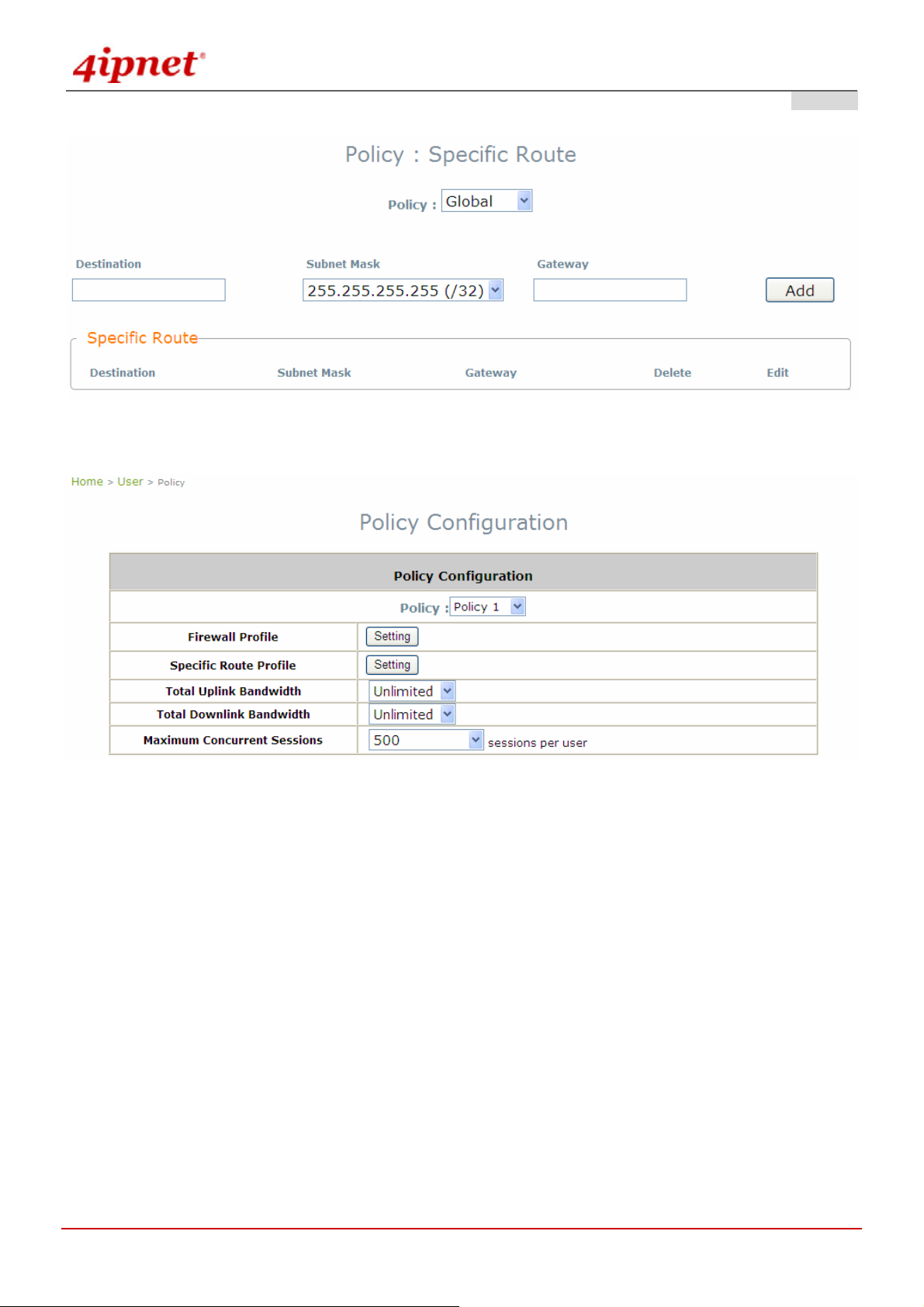
User’s Manual
Policy 1 ~ Policy 16:
OWL800 / OWL2000 / HSG800 ENGLISH
Gateway Mode >> Individual Policy
Firewall Profile: Each Policy has a firewall service list and a set of firewall profile consisting of firewall rules.
Specific Route Profile: The default gateway of WAN1, WAN2, or a desired IP address can be defined in a
policy. When Specific Default Route is enabled, all clients applied this policy will access the Internet through
this default gateway.
Schedule Profile: The Schedule table in a 7x24 format is used to control the clients’ login time. When
Schedule is enabled, clients applied policies are only allowed to login the system at the time which is checked
in the applied policy.
Total Uplink Bandwidth: Defines the maximum uplink bandwidth allowed to be shared by all clients.
Total Downlink Bandwidth: Defines the maximum d ownlink bandwidth allowed to be shared by all client s.
Maximum Concurrent Sessions: Set the maximum concurrent sessions for each client.
© 2008 4IPNET, INC.
70

User’s Manual
OWL800 / OWL2000 / HSG800 ENGLISH
4.4.5 Firewall
Firewall rules in the Global Policy or individual Policy (1 ~ 16) can be defined to filter the traffic that travels through
the system. When a packet matches the specified Source, Destination, and Protocol, the corre sponding Action
(Pass or Block) will be taken.
Gateway Mode >> Global Firewall
Gateway Mode >> Policy Firewall
To add a rule to the Firewall list, specify the values of following fields and click the Add button. A rule in the list can
be deleted (Delete button) from the list or edited (Edit button).
Source IP / Subnet Mask: The combination of these two fields specifies either the IP address of a source host
or the source network segment. For example, 192.168.1.101 with 255.255.255. 255 (/32) st ands for a single host
- 192.168.1.101, while 192.168.1.0 with 255.255.255.0 (/24) indicates this is a Class C subnet - 192.168.1.xxx.
Destination IP / Subnet Mask: The combination of these two fields specifies either the IP address of a
destination host or the destination network segment. For example, 192.168.2.101 with 255.255.255.255 (/32)
stands for a single host - 192.168.2.101, while 192.168.2.0 with 255.255.255.0 (/24) indicates this is a Class C
© 2008 4IPNET, INC.
71

User’s Manual
OWL800 / OWL2000 / HSG800 ENGLISH
subnet - 192.168.2.xxx.
Protocol: The specific service protocol for the filtering rule - ALL, TCP/UDP, TCP, UDP, ICMP, and IP.
Action: Pass is to allow the packet to pass; Block is to block the packet from passing.
© 2008 4IPNET, INC.
72

User’s Manual
OWL800 / OWL2000 / HSG800 ENGLISH
4.4.6 Route
Static ro uting rule s in the Global Policy or individual Po licy (1 ~ 24 ) can be defined to spe cifically route the tra f fic that
travels through the system. When no rule is defined, all traffic will go through the system’s default gateway (WAN
interface).
Gateway Mode
To add a rule to the Specific Route list, specify the values of following fields and click the Add button. A rule in the
list can be deleted (Delete button) from the list or edited (Edit button).
Destination / Subnet Mask: The combination of these two fields specifies the IP address of a destination host
or the destination network segment.
Gateway: The IP address of the gateway for the destination host or network segment.
© 2008 4IPNET, INC.
73

User’s Manual
OWL800 / OWL2000 / HSG800 ENGLISH
4.4.7 802.1X
OWL800 supports 802.1X authentication. In the Supplica nt <-> Authenticator <-> Authentication Server architecture,
The system will only allow 802.1X-enabled devices (Authenticator) to send 802.1X authentication req uest to intern al
or external RADIUS server. For more information, please see Appendix B. 802.1X Support.
Gateway Mode
Type
Disable: The 802.1X authentication request from the IP address or network segment of 802.1 X-enabled client
devices or the remote gateway is not allowed.
802.1X: The client device is 802.1X-enabled, such as AP and switch.
Roaming Out: The device is the remote gateway to send authentication request of “Roaming Out User”.
To add to the Device Setting List, configure Type, IP Address, Subnet Mask and Secret Key in the Add column;
click Add.
Gateway Mode >> Add Roaming Out and 802.1X list
IP Address / Subnet Mask: The combination of the se two fields specifies the I P addre ss or netwo rk se gment of
802.1 X-enabled client devices or the remote gateway.
Security Key: Security key for the authentication.
© 2008 4IPNET, INC.
74

User’s Manual
OWL800 / OWL2000 / HSG800 ENGLISH
4.5 Utilities
This section provides information on four utilities used for customizing and maint aining the system, including
Change Password, Import & Export, Backup & Restore, System Upgrade, Reboo t, Scan and Upload
Certificate.
4.5.1 Change Password
To protect the administration web site from unauthorized access, it is strongly recommended to change the default
administrator's password to your own one. Only alpha-numeric characters pattern is allo wed and it is strongly
recommended to take a combination of both numeric and alphabetic characters.
Gateway Mode
AP Mode
The administrator/manager/operator can change the passwords of the system. The login account for the
administrator is “admin”. The admin password of the system can be changed here by entering the new password.
The default admin password of the system is "admin". Click Apply to activate the new passwords.
© 2008 4IPNET, INC.
75

User’s Manual
OWL800 / OWL2000 / HSG800 ENGLISH
4.5.2 Import & Export
Gateway Mode
Import Local User: Click Browser button to select the file for uploaded user account and then click Import
to execute the process.
Export Local User: Click Export button to create all build-in user account information and cl ick Open or
Save to view or save the user’s file.
© 2008 4IPNET, INC.
76

User’s Manual
OWL800 / OWL2000 / HSG800 ENGLISH
4.5.3 Backup & Restore
This function is used to backup and to restore the OWL800 settings. The OWL800 can also be re stored to the
factory default settings using this function. It can be used to duplicate settings to other access points (backup
settings and then restore in another AP).
Gateway & AP Mode
Reset to Default: Click Reset to load the factory default settings of the OWL800. After confirming this
action, the system will reset all parameters. Reboot to let the default settings takes effect.
Backup System Settings: Click Backup button to save the current system configuratio ns to a backup file
on a local disk of the management console. A backup file for OWL800 keeps the current system settings as
well as the local user accounts. Before any configuration changed, it is recommended to backup the sy stem
before you proceed with any changes; thus, it can be recovered soon if occasionally something wrong
happened.
Restore System Settings: Click on the Browse button to select configuration file to resto re, and then,
press Upload to proceed. After confirming the action, the system will start to replace the existing settings
with this newly upload one; reboot the system as required to ensure the parameter changes take effect.
Since network parameters have been reset/restored, the administrat or may need to change PC’s network
settings in order to match OWL800’s default settings.
© 2008 4IPNET, INC.
77

User’s Manual
OWL800 / OWL2000 / HSG800 ENGLISH
4.5.4 System Upgrade
OWL800 provides Web firmware upload/upgrade feature. While the new firmware is obtained, it has to put locally in
the administrator’s computer. The u sers can easily download the latest firmware from the website and upgrade the
system. To upgrade the system firmware, click Browse button to choose the new firmware file and then click Apply
button to execute the process. There will be a prompt confirmation message appearing to notify the administrator to
restart the system after successful firmware upgra de.
Gateway & AP Mode
Although the system will check the firmware's contents to ensure its integrity, it is still recommended to check the
version number before action proceeded.
Please note that firmware upgrade may sometime result in loss of some data. Please ensure that you read the
release notes to understand the limitations before upgrading the firmware. Please restart the system after
upgrading the firmware.
Do not power on/off the system during the upgrade or the restart process as it may damage the system.
For further information of available firmware version, please conta ct local dealers.
© 2008 4IPNET, INC.
78

User’s Manual
OWL800 / OWL2000 / HSG800 ENGLISH
4.5.5 Reboot
This function allows the administrator to restart the OWL800 safely. The process should take about three minutes.
Click Reboot button to restart the system. Please wait for the blinking timer to finish before accessing the system
web management interface again.
Occasionally, it is necessary to reboot OWL800 to ensure parameter changes being submitted. Take this page for
the purpose.
Gateway & AP Mode
© 2008 4IPNET, INC.
79
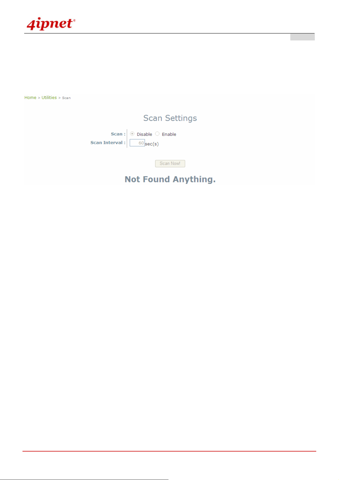
User’s Manual
OWL800 / OWL2000 / HSG800 ENGLISH
4.5.6 Scan
OWL800 provides this Scan feature for users to figure out the wireless status from the view of VAPs. It probes the
WLAN and retrieves the information from clients. Thus, while compare scan result to the VAPs settings, it can avoid
unexpected conflict in settings and tune the corresponding parameters.
Gateway & AP Mode
Scan: Enable or Disable scan settings.
Scan Interval: The time interval used to trigger the scanning, it takes 86400 seconds as the default setting.
The result table records the latest AP scanning result. St ill, the user coul d cli ck the Scan Now button agai n to ren ew
the result immediately. Take the result to compare with the AP's setting and status and tune necessary AP settings.
© 2008 4IPNET, INC.
80
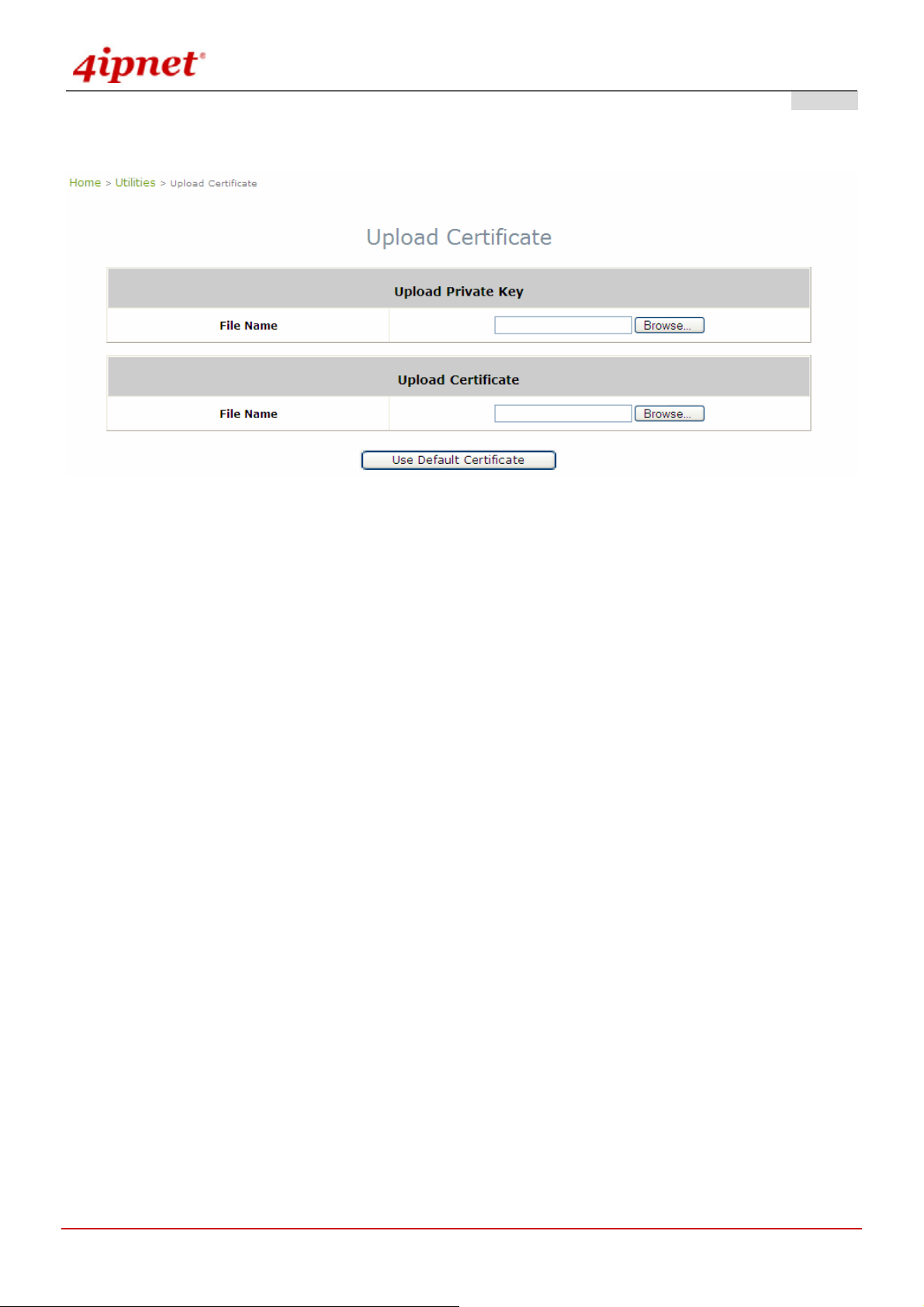
User’s Manual
4.5.7 Upload Certificate
OWL800 / OWL2000 / HSG800 ENGLISH
Gateway & AP Mode
The administrator can upload new private key and customer certification, external certificate issued by pub lic or
private authority.
Click the first Browse button to select the Private Key or Certificate. Click the second Browse button to se lect the
file for the certificate upload. Next, click Save to complete the upload process. Click Use Default Certificate button
to restore the default certificate automatically.
© 2008 4IPNET, INC.
81
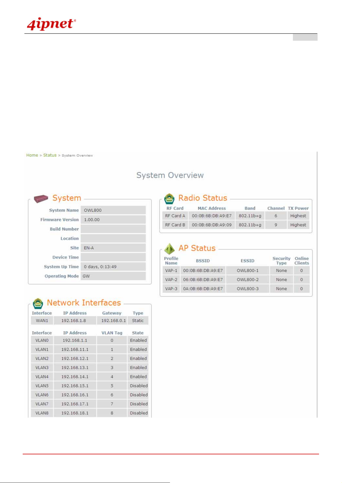
User’s Manual
OWL800 / OWL2000 / HSG800 ENGLISH
4.6 Status
This section provides information on the following functions: System Overview, WDS List, Antennas,
Associated Clients, Event Log, Online Users and User Log.
4.6.1 Overview
The section provides an overview of the system status for the administrator. System's overall status, for individual
setting and status, please check them in each configuration page.
Gateway Mode
© 2008 4IPNET, INC.
82

User’s Manual
OWL800 / OWL2000 / HSG800 ENGLISH
AP Mode
© 2008 4IPNET, INC.
83
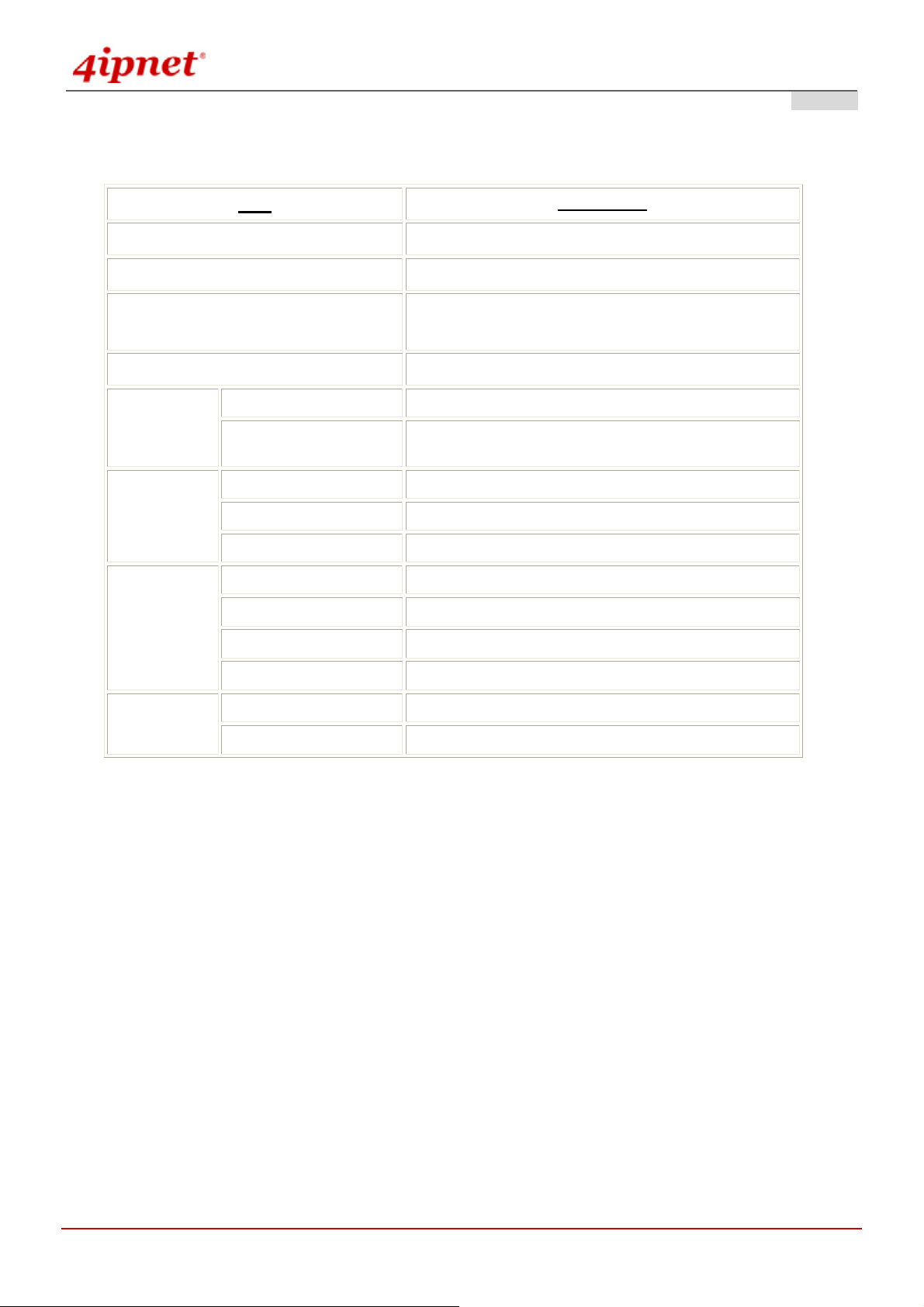
User’s Manual
The description of the table is as the following:
OWL800 / OWL2000 / HSG800 ENGLISH
Firmware Version
System Name
System Up Time
Network
Interface
LAN
Interface
Radio Status
Item
Device Time
MAC Address
IP Address
MAC Address
IP Address
Subnet Mask
MAC Address
Band
Channel
Description
The present firmware version of OWL800
The system name. The default is OWL800
The network time server that the system is set to
align.
The system time is shown as the local time.
The MAC address of Network Interface
The IP address of the Network Interface
The MAC address of LAN Interface
The IP address of the LAN Interface
The Subnet Mask of the LAN Interface
The MAC address of Radio module
The RF band(a/b/g) used
The channel specified
Radio module
BSSID
The RF module used for AP
Basic Service Setting ID
AP Status
ESSID
Extended Service Setting ID
© 2008 4IPNET, INC.
84
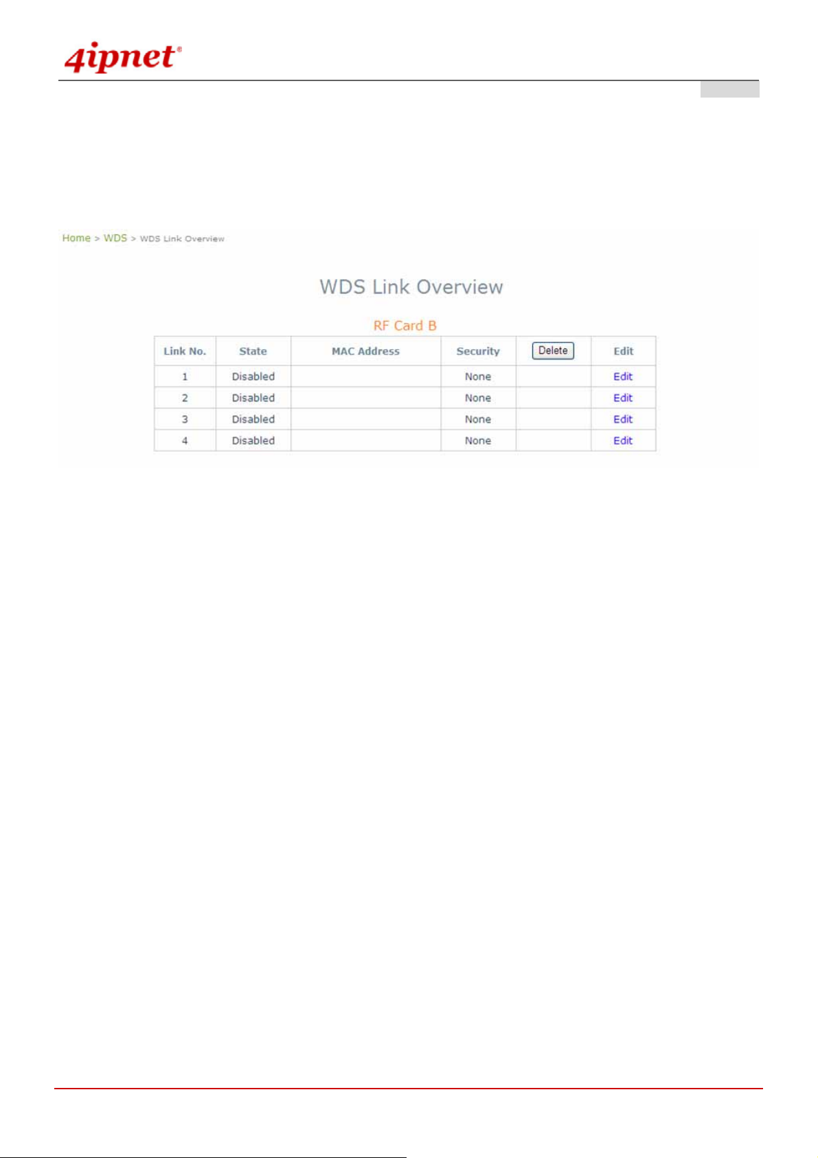
User’s Manual
OWL800 / OWL2000 / HSG800 ENGLISH
4.6.2 WDS List
WDS lists indicate the link status of each RF interface including status of Mac Address, SNR dB, rate, count and
errors.
Gateway & AP Mode
© 2008 4IPNET, INC.
85
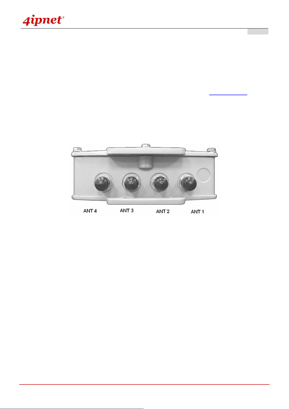
User’s Manual
OWL800 / OWL2000 / HSG800 ENGLISH
4.6.3 Antennas
Antenna Diversity is an important feature of the 802.11 specification. The two radio modules (CM9) inside the
system support the feature of Antenna Diversity. Each of them comes with two antenna connectors for connecting
up to two antennas. When the feature of antenna diversity is turned on, the module uses two receiving antennas to
eliminate mulitpath signal distortion. That is, the signal from the antenna with the least noise (best SNR) is chosen,
and the other antenna is ignored. For more explanation please refer to the wiki page on Antenna Diversity
.
To support the Antenna Diversity, each radio module (CM9) inside has two antenna connectors - one “Main”
connector and the other as “Auxiliary” connector. The “Main” connector must be connected with an antenna. The
“Auxiliary” is optionally connected to an antenna.
The above picture represents ANT 1 ~ ANT 4 connectors from right to left when OWL800 chassis (with Mylar) is
faced up.
ANT1: The “Main” connector of 1
ANT2: The “Main” connector of 2
ANT3: The “Auxiliary” connector of 1
ANT4: The “Auxiliary” connector of 2
st
radio module. Antenna at this connector is required.
nd
radio module. Antenna at this connector is required.
st
radio module. Antenna at this connector is optional.
nd
radio module. Antenna at this connector is optional.
Each of the two radio module (CM9) inside has two antenna connectors for antenna diversity. The required
antenna is antenna ANT1 and antenna ANT3. ANT1 is connected to the “Main” contact point of the first radio
module. ANT3 is connected to the “Main” contact of the second module.
© 2008 4IPNET, INC.
86

User’s Manual
OWL800 / OWL2000 / HSG800 ENGLISH
4.6.4 Associated Clients
List all associated clients from all the VAPs. Please take this table to manage the clients and take the signal
strength for debug purpose.
Gateway & AP Mode
© 2008 4IPNET, INC.
87

User’s Manual
OWL800 / OWL2000 / HSG800 ENGLISH
4.6.5 Event Log
Gateway & AP Mode
Event log provides the system activities records and monitor the system status by che cking this log.
In the log, normally , each line represent an event reco rd; And in each line, there are fields su ch as Date, T ime, Nam e
or Status.
Date/Time : The time & date when the event happened
Hostname: Indicate which host records this event. Note that all events in this page are local event, so events of
this field are all the same. However in remote syslog service, this field will help us to identify which event are
from this OWL800.
Process name (with square brackets): Indicate the event generated by this run ning instance
To save the file locally or clear all the records, press Save Log or Clear button respectively.
© 2008 4IPNET, INC.
88

User’s Manual
OWL800 / OWL2000 / HSG800 ENGLISH
4.6.6 Online Users
All online users’ information can be obtained by using this function. These include User name, IP Address, MAC
Address, Idle Time, and Action. The administrator can use this functio n to force a specific online u ser to log out, or
terminate any user session by clicking the hyperlink of Action.
Gateway & AP Mode
© 2008 4IPNET, INC.
89

User’s Manual
OWL800 / OWL2000 / HSG800 ENGLISH
4.6.7 User Log
This function is used to check the history of the system and it will be kept up to 3 days. All records are sorted by date
and listed accordingly . Plea se note that these records are stor ed on the volatile memory and wil l be lost if the system
is powered off.
Gateway & AP Mode
Users Log: The Users Log provides information of all users' login and logout activities except guest users,
RADIUS roaming in/out users, and SIP clients.
Session Log: Log each connection created by clients and tracking the source IP and destination IP. Session
Log can be sent to the SYSLOG server or via email automatically. In addition, it can be uploaded to a FTP
server periodically.
© 2008 4IPNET, INC.
90

User’s Manual
OWL800 / OWL2000 / HSG800 ENGLISH
Appendix A. Session Limit and Session Log
Session Limit
To prevent ill-behaved clients or malicious software from using up system’ s con nection reso urces, admini strators will
have to restrict the number of concurrent sessions that a client can establish.
¾ The maximum number of concurrent sessions (TCP and UDP) for each user can be specified in the policy
setting, which can be chosen to apply to all users including authenticated users, users on
non-authenticated ports, privileged users, and clients in virtual server and DMZ zones.
¾ When the number of a user’s sessions reaches the session limit (a choice of Unlimited, 10, 25, 50, 100,
200, 350, and 500), the user will be implicitly suspended upon receipt of any new connection request. In
this case, a record will be logged to the SYSLOG server specified in the Policy Configuration.
¾ Since this basic protection mechanism may not be able to protect the system from all malicious DoS
attacks, it is strongly recommended to build some immune cap abilities (such as IDS or IPS solutions) in the
network deployment to protect the network in daily operation.
Session Log
The system can record connection details of each client while accessing the Internet. In addition, the log data can be
sent out to a specified SYSLOG Server, Email Box or FTP Server based on pre-defined time interval.
© 2008 4IPNET, INC.
91
 Loading...