How it Works
Log In / Sign Up
Buy Points
How it Works
FAQ
Contact Us
Questions and Suggestions
Users
4ipnet
Loading...
A
AP-952X
E
EAP100
EAP110
EAP200
EAP210
EAP220
EAP260
EAP300
EAP330
EAP701
EAP705
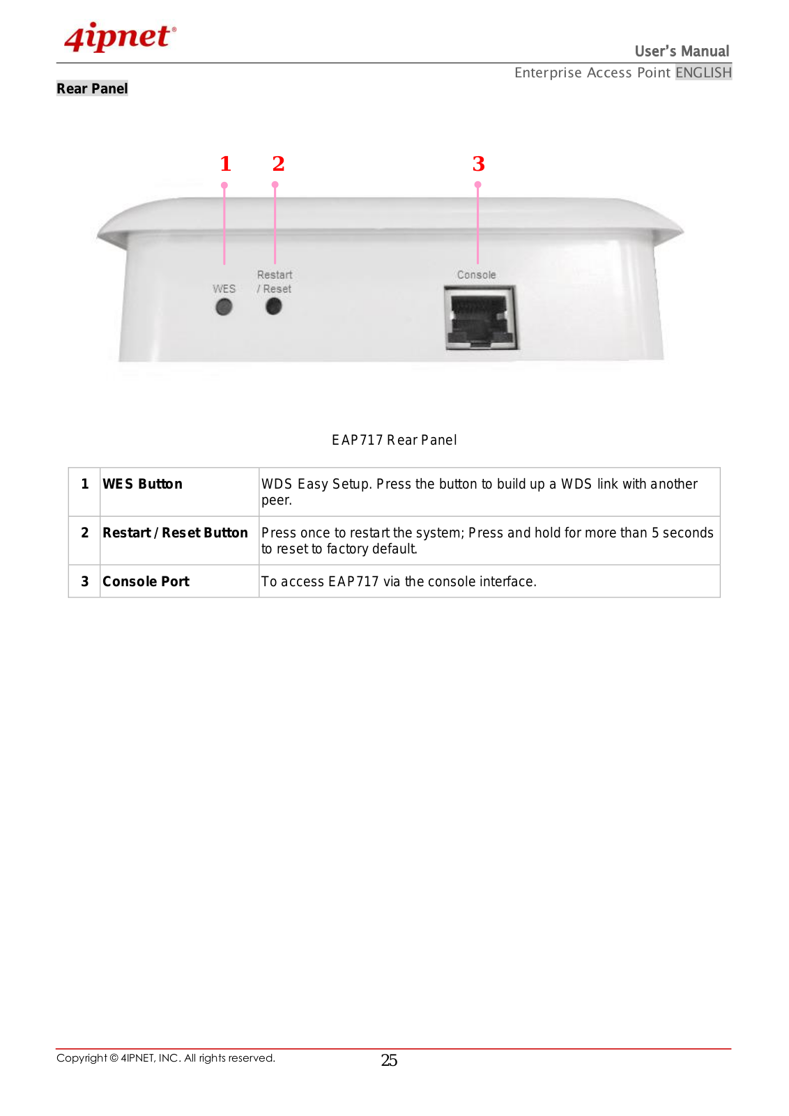
EAP717
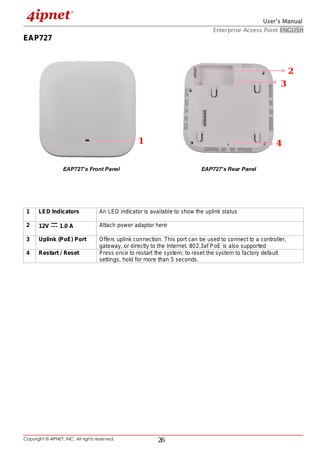
EAP727
EAP737
EAP738
EAP740
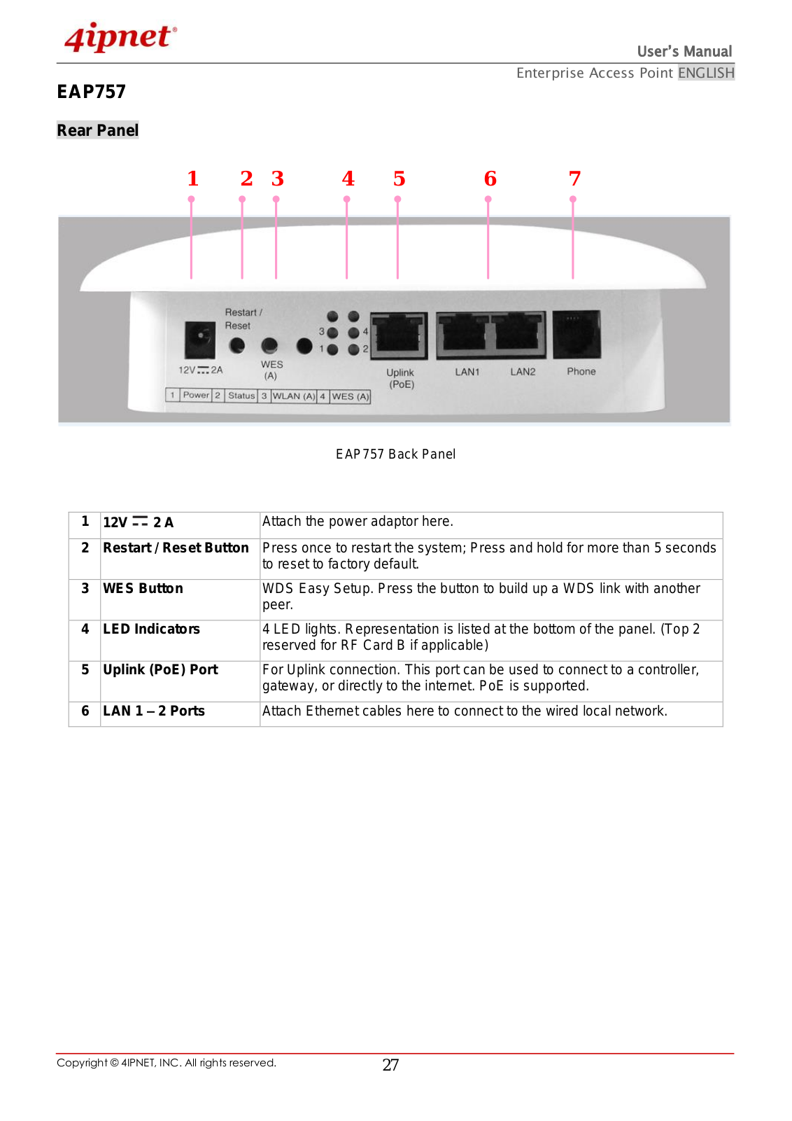
EAP747
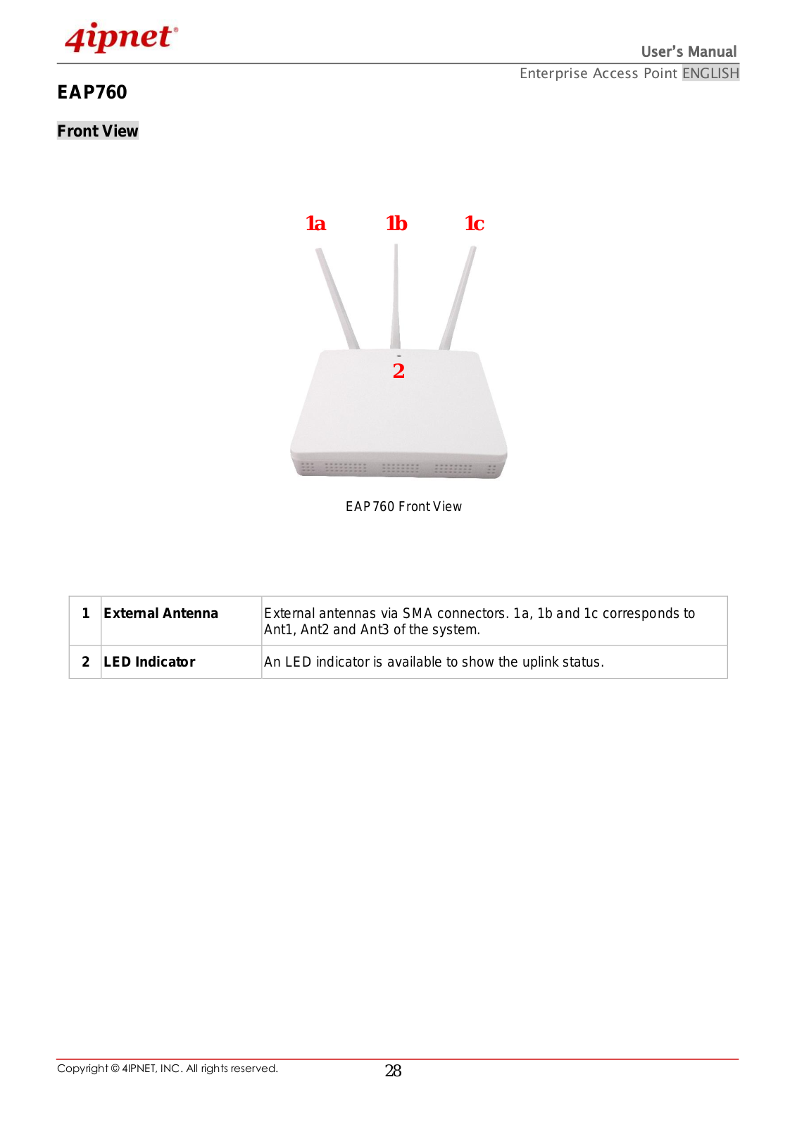
EAP750
EAP767
2
H
HSG200
HSG800
M
MSG100
O
OWL2000
OWL400
OWL410
2
OWL500
OWL510
OWL530
OWL550
OWL630
OWL800
S
SDS200W
W
WHG301
2
WM-MB92M
Loading...
Loading...
Nothing found
EAP220
User Manual
166 pgs
6.45 Mb
0
Table of contents
Loading...
4ipnet EAP220 User Manual
...
4ipnet User Manual
Download
Specifications and Main Features
Frequently Asked Questions
User Manual
Download
Loading...
+
hidden pages
Unhide
You need points to download manuals.
1 point = 1 manual.
You can buy points or you can get point for every manual you upload.
Buy points
Upload your manuals
 Loading...