

Page 1
ENGLISH
Liquid Crystal Projector
USER'S MANUAL
USER'S MANUAL
ENGLISH-1
Thank you for purchasing this liquid crystal projector.
CONTENTS
CONTENTS
Page
FEATURES .......................................2
BEFORE USE ...................................2
Contents of Package ..............................2
Part Names.............................................3
Loading the Batteries..............................5
INSTALLATION ................................6
Installation of the Projector and Screen
........6
Angle Adjustment ...................................6
Cabling ...................................................7
Power Connection ..................................8
Example of System Setup ......................8
Plug & Play.............................................8
OPERATIONS...................................9
Power On ...................................................9
Power Off
................................................9
Basic Operation....................................10
Setup Menu ..........................................12
Input Menu............................................13
Image Menu..........................................14
Options Menu .......................................15
No Signal Menu....................................16
MAINTENANCE ..............................17
Lamp.....................................................17
Air Filter ................................................19
Other Maintenance...............................19
Page
TROUBLESHOOTING ....................20
OSD Message ......................................20
Indicators Message ..............................21
Symptom ..............................................22
SPECIFICATIONS...........................23
.......................................................................................
TABLES
Table 1. Installation Reference.................6
Table 2. Cabling .......................................7
Table 3. Basic Operations ......................10
Table 4. Setup Menu ..............................12
Table 5. Input Menu................................13
Table 6. Image Menu..............................14
Table 7. Options Menu ...........................15
Table 8. No Signal Menu........................16
Table 9. OSD Message ..........................20
Table 10. Indicator Message ..................21
Table 11. Symptom ................................22
Table 12. Specifications .........................23
.......................................................................................
For "TECHNICAL" and "REGULATORY
NOTICE", see the end of this manual.
• The information in this manual is subject to change without notice.
• The manufacturer assumes no responsibility for any errors that may appear in this manual
• The reproduction, transmission or use of this document or contents is not permitted without
express written authority.
TRADEMARK ACKNOWLEDGMENT : PS/2, VGA and XGA are registered trademarks of
International Business Machines Corporation. Apple, Mac and ADB are registered trademarks of
Apple Computer, Inc. VESA and SVGA are trademarks of the Video Electronics Standard
Association. Windows is a registered trademark of Microsoft Corporation. Carefully observe the
trademarks and registered trademarks of all companies, even when not mentioned.
NOTE
WARNING • Please read the accompanying manual “Product Safety Guide”
and this “USER'S MANUAL” thoroughly to ensure correct usage through
understanding. After reading, store this instruction manual in a safe place for
future reference.
01MP877501.4.139:52AMページ1
Page 2
ENGLISH-2
FEATURES
FEATURES
This liquid crystal projector is used to project various computer signals as well as NTSC / PAL /
SECAM video signals onto a screen. Little space is required for installation and large images can
easily be realized.
Outstanding Brightness
The UHB lamp and high-efficiency optical system assure a high level of brightness.
Partial Magnification Function
Interesting parts of images can be magnified for closer viewing.
Distortion Correction Function
Distortion-free images are quickly available.
BEFORE USE
BEFORE USE
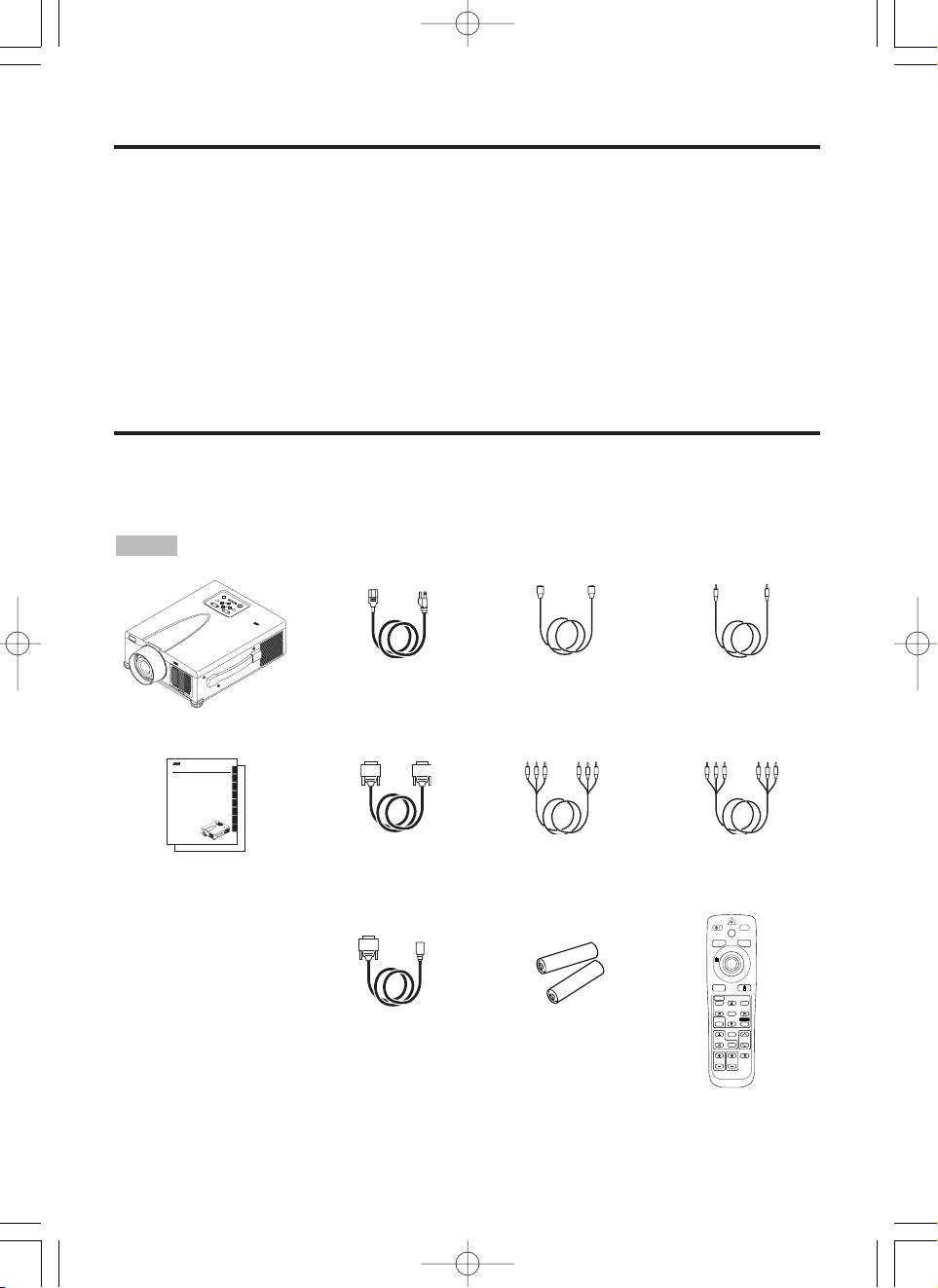
Contents of package
Make sure all of the following items are included in the package. If anything is missing, please
contact your dealer.
• Keep the original packing material for future reshipment.
NOTE
M
P
8
7
7
5
+
Z
O
O
M
M
U
T
E
I
N
P
U
T
S
T
A
N
D
B
Y
O
N
R
E
S
E
T
P
O
W
E
R
L
A
M
P
T
E
M
P
M
E
N
U
+
F
O
C
U
S
MP8775
P
O
R
T
A
BL
E
P
R
O
JE
C
TO
R
Projector
User’s Manual
Product Safety Guide
Registration Card
Power Cord x 3
(US, UK, Europe)
RGB Cable Video/Audio Cable
(with white lead)
Mouse cable x 3
(PS/2, ADB, Seral)
STANDBY/ON
LASER
VIDEO
BLANK
RGB
AUTO
MENU
MENU SELECT
POSITION
RESET
FREEZE
MAGNIFY
PinP
OFF
VOLUME
MUTE
ZOOMFOCUS
Remote Control
Transmitter
Batteries
for Remote Control
Transmitter
Component
Video Cable
(with green lead)
ENGLISH
FRANÇAIS
DEUTSCH
ITALIANO
ESPAÑOL
NORSK
NEDERLANDS
TECHNICAL
Multimedia Projector
MP8775
USER'S MANUAL
Please read this user's manual thoroughly to ensure correct usage through understanding.
MANUEL D'UTILISATION
Nous vous recommandons de lire attentivement ce manuel pour bien assimiler le
fonctionnement de l'appareil.
BEDIENUNGSANLEITUNG
Bitte lessen Sie diese Bedienungsanleitung zugunsten der korrekten Bedienung
aufmerksam.
MANUALE D'ISTRUZIONI
Vi preghiamo voler leggere attentamente il manuale d'sitruzioni in modo tale da poter
comprendere quanto riportato ai fini di un corretto utilizzo del proiettore.
MANUAL DE USUARIO
Lea cuidadosamente este manual del usuario para poder utilizar corretamente el
producto.
BRUKERHÅNDBOK
Vennligst les denne bruksanvisningen grundig for å være garantert driftssikker bruk.
GEBRUIKSAANWIJZNG
Lees voor het qebruik alstublieft deze handleiding aandachtig door, om volledig profijt te
hebben van de uitgebreide mogelijkheden.
TECHNICAL
REGULATORY NOTICES
MP8775
+
Z
O
O
M
M
U
T
E
I
N
P
U
T
S
T
A
N
D
B
Y
O
N
R
E
S
E
T
P
O
W
E
R
L
A
M
P
T
E
M
P
M
E
N
U
+
F
O
C
U
S
M
P
8
7
7
5
P
O
R
T
A
B
L
E
P
R
O
J
E
C
T
O
R
S-Video Cable
(Mini DIN4-pin)
Stereo Mini Jack
Cable
01MP877501.4.139:52AMページ2
Page 3
M
P
8
7
7
5
+
ZOOM
M
U
T
E
I
N
P
U
T
STANDBY ON
R
E
S
E
T
P
O
W
E
R
L
A
M
P
T
E
M
P
M
E
N
U
+
F
O
C
U
S
MP8775
P
O
R
T
A
B
L
E
P
R
O
J
E
C
T
O
R
ENGLISH-3
BBBBEEEEFFFFOOOORRRREEEE UUUUSSSSEEEE ((((ccccoooonnnnttttiiiinnnnuuuueeeedddd))
))
ENGLISH
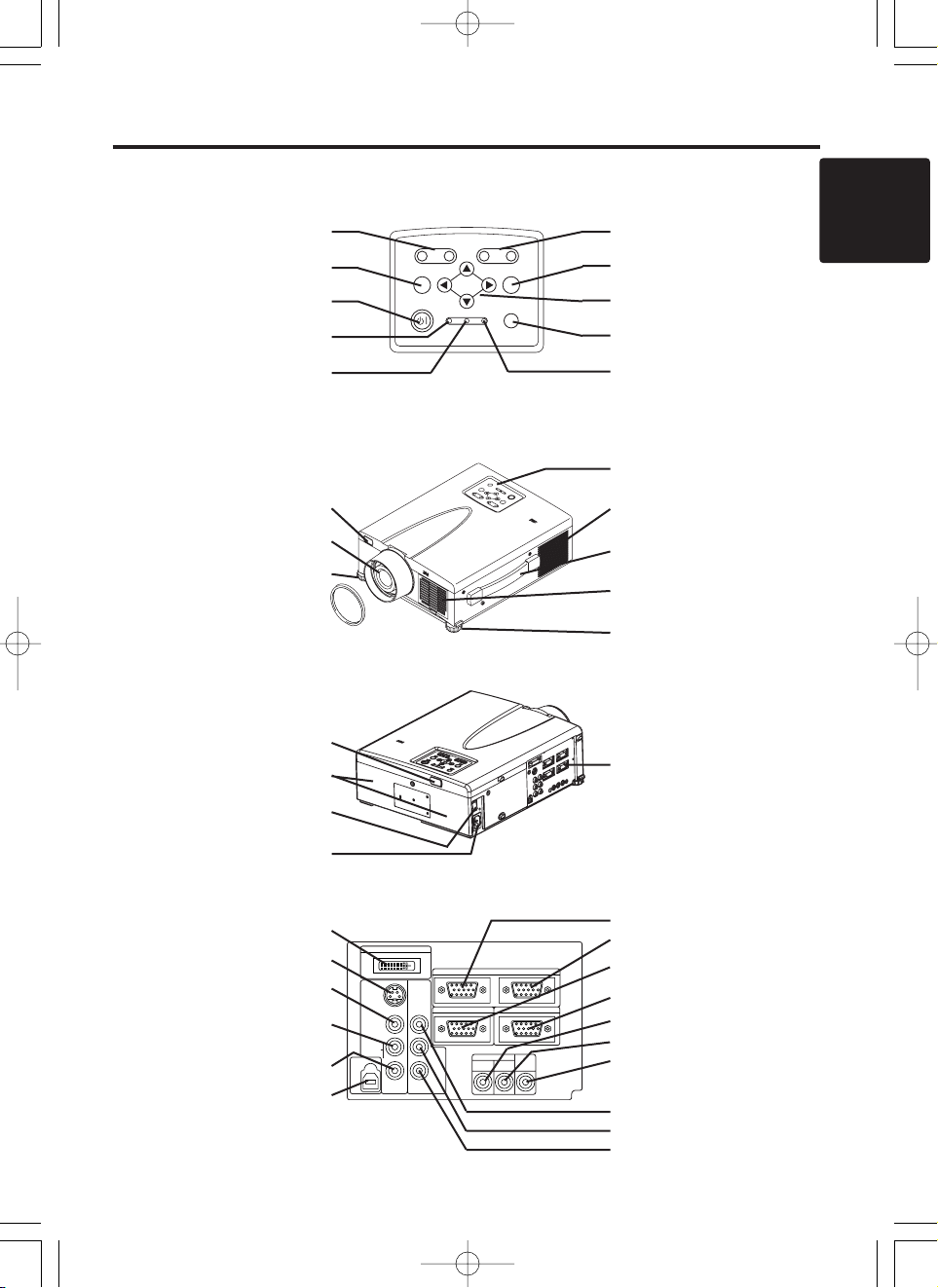
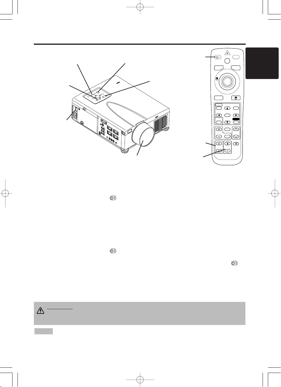
Part Names
Control Panel
(Refer to P.9 "OPERATIONS")
Front/Right View
M
P
8
7
7
5
P
O
R
T
A
B
L
E
P
R
O
J
E
C
T
O
R
Rear/Left View
Terminal Panel
(Refer below)
Terminal
Panel
DIGITAL Terminal
S-VIDEO Terminal
VIDEO Terminal
AUDIO(MONO)/L
Terminal
AUDIO R Terminal
USB Terminal
AUDIO IN AUDIO
OUT
RGB 1
DIGITAL
RGB 2
RGB OUT
CONTROL
RGB IN 2
COMPO
NENT
VIDEO
S-VIDEO
VIDEO
(MONO)/L
AUDIO
R
C
B/PB
CR/PR
DIGITAL
USB
+
ZOOM
MUTE INPUT
STANDBY ON
RESET
LAMP TEMP
MENU
+
––
FOCUS
ZOOM Button
MUTE Button
STANDBY/ON Button
LAMP Indicator
POWER Indicator
FOCUS Button
INPUT Button
MENU Button
RESET Button
TEMP Indicator
Remote Control Sensor
Lens
Foot Adjuster
Lens Cap
Control Panel
Ventilation Openings
(exhaust)
Carrying Handle
Air Filter and Intake
for the Cooling Fan
Foot Adjuster
Remote Control Sensor
Speaker
Power Switch
AC Inlet
(to Power Cord)
RGB IN 1 Terminal
RGB IN 2 Terminal
RGB OUT Terminal
CONTROL Terminal
AUDIO IN RGB1 Terminal
AUDIO IN RGB2 Terminal
AUDIO OUT Terminal
COMPONENT VIDEO
Y Terminal
C
B/PB Terminal
C
R/PR Terminal
01MP877501.4.139:52AMページ3
Page 4
ENGLISH-4
BBBBEEEEFFFFOOOORRRREEEE UUUUSSSSEEEE ((((ccccoooonnnnttttiiiinnnnuuuueeeedddd))
))
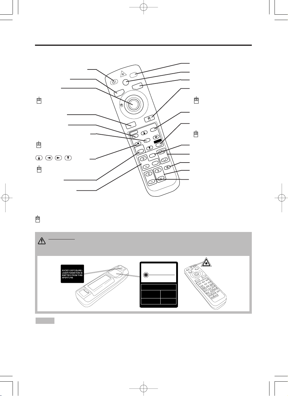
Part Names (continued)
S
T
A
N
D
B
Y
/O
N
LASER
VIDEO
BLANK
RGB
AUTO
MENU
MENU SELECT
POSITION
R
ESET
FR
EEZE
M
A
G
N
IF
Y
PinP
OFF
VOLUME
MUTE
ZOOM
FOCUS
REMOTE CONTROL TRANSMITTER
(Refer to P.9 "OPERATIONS")
To prevent any malfunction;
• Do not exert excessive physical force on the remote control transmitter. Take care not to drop.
• Do not place the heavy objects on the remote control transmitter.
• Do not wet the remote control transmitter or place it on any wet object.
• Do not place the remote control transmitter close to the cooling fan of the projector.
• Do not disassemble the remote control transmitter in case of malfunction. Please send to a
servicing dealer.
NOTE
CAUTION
LASER RADIATIONDO NOT STARE INTO BEAM
WAVE LENGTH: 650nm
MAX . OUTPUT: 1mW
CLASS 2 LASER PRODUCT
RADIAZIONI LASER
NON GUARDARE NEL RAGGIO LUCE
APPARECCHIO LASER DI CLASSE 2
RAYONNEMENT LASER
NE PAS REGARDER DANS
LE FAISCEAU APPAREIL
A LASER DE CLASSE 2
LASER-STRAHLUNG
NICHT IN DEN STRAHL
BLICKEN LASER KLASSE2
MANUFACTURED
PLACE OF
MANUFACTURER:A
MADE IN JAPAN
IEC60825-1:1993+A1:1997
STANDBY/ON Button
LASER Button
BLANK Button
Disk Pad
Used to operate the
mouse shift function and
left click function.
AUTO Button
MENU Button
MENU SELECT Button
Used to click the left
mouse button.
, , , Button
Used to operate the
mouse shift function.
MAGNIFY Button
VIDEO Button
RGB Button
MOUSE / RIGHT Button
Used to click the right
mouse button.
RESET Button
Used to click the right
mouse button.
VOLUME Button
FREEZE Button
MUTE Button
POSITION Button
ZOOM Button
These functions work when the mouse control function is activated. Remember, the POSITION,
BLANK ON and MENU ON functions disable the mouse control function.
WARNING • The laser pointer of the remote control transmitter is used in
place of a finger or rod. Never look directly into the laser beam outlet or point
the laser beam at other people. The laser beam can cause vision problems.
FOCUS Button
PinP Button
01MP877501.4.139:52AMページ4
Page 5
ENGLISH-5
BBBBEEEEFFFFOOOORRRREEEE UUUUSSSSEEEE ((((ccccoooonnnnttttiiiinnnnuuuueeeedddd))
))
ENGLISH
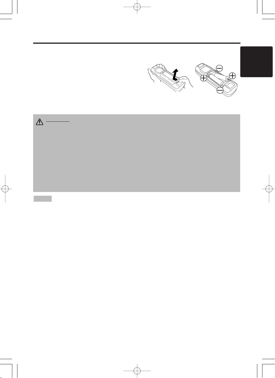
Loading the Batteries
Install the AA batteries into the remote control
transmitter.
1. Remove the battery cover.
Push the knob while lifting up the battery cover.
2. Load the batteries.
Make sure the plus and minus poles are correctly
oriented.
3. Close the battery cover.
1
2
Replace the batteries when remote control transmitter operation becomes difficult.
NOTE
CAUTION • Use only the specified batteries with this remote control
transmitter. Also, do not mix new and old batteries. This could cause
battery cracking or leakage, which could result in fire or personal injury.
• When loading the batteries, make sure the plus and minus terminals are
correctly oriented as indicated in the remote control transmitter. Incorrect
orientation could cause battery cracking or leakage, which could result in
personal injury or pollution of the surrounding environment.
• When you dispose the battery, you should obey the law in the relative area or
country.
• Keep the battery away from children and pets.
• When not to be used for an extended period, remove the batteries from the
remote control transmitter.
01MP877501.4.139:52AMページ5
Page 6
ENGLISH-6
INSTALLATION
INSTALLATION
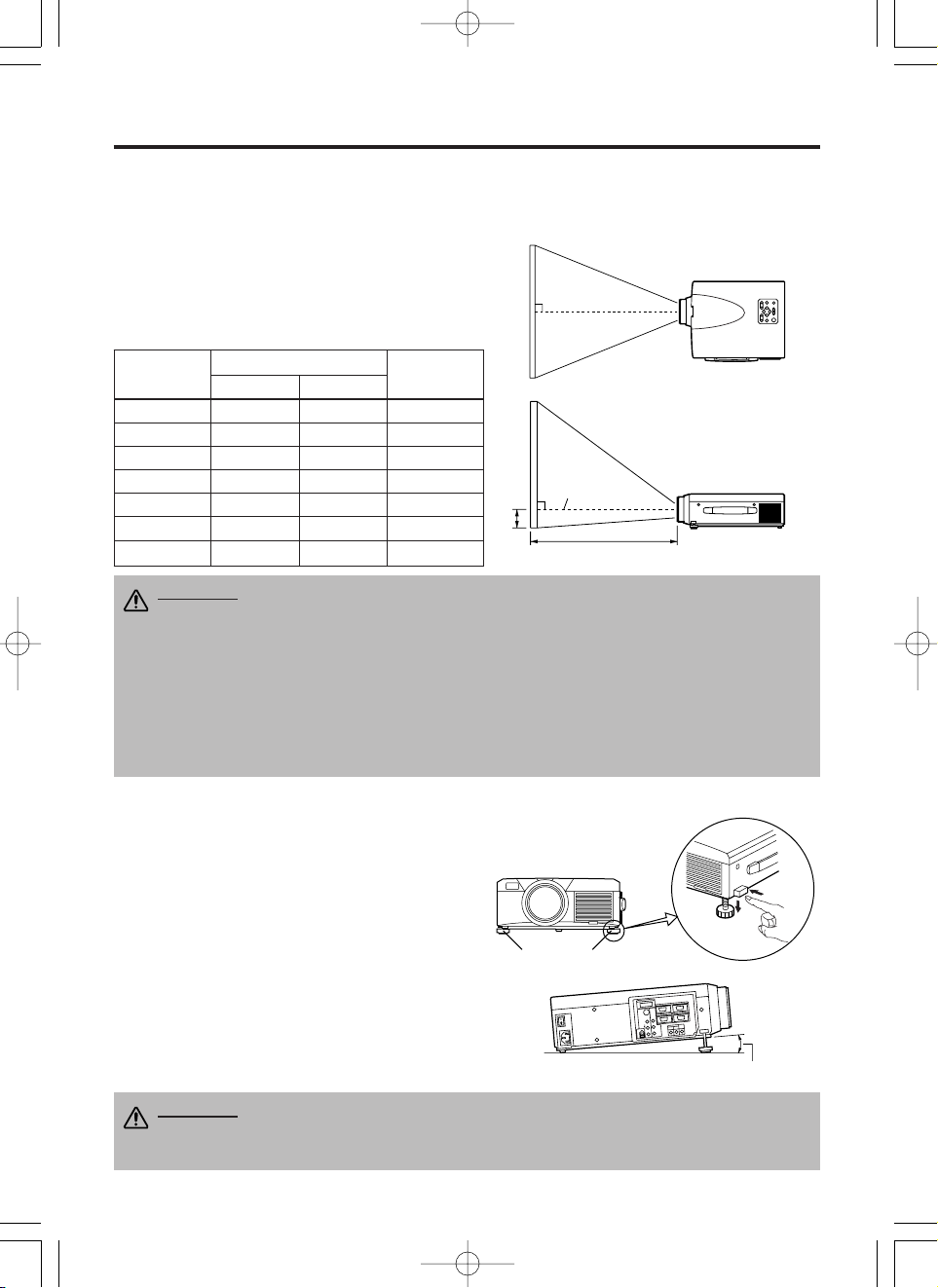
Installation of the Projector and Screen
Refer to the drawing and table below for determining the screen size and projection distance.
Top View
Side View
Screen size
[inches (m)]
a [inches (m)]
b
[inches (cm)]
Min. Max.
40 (1.0) 55 (1.4) 73 (1.9) 1 (3)
60 (1.5) 85 (2.2) 114 (2.9) 2 (4)
80 (2.0) 114 (2.9) 151 (3.8) 2 (6)
100 (2.5) 144 (3.7) 191 (4.9) 3 (7)
120 (3.0) 176 (4.5) 231 (5.9) 3 (9)
150 (3.8) 220 (5.6) 282 (7.2) 4 (11)
200 (5.0) 291 (7.4) 386 (9.8) 6 (15)
Angle Adjustment
Use the foot adjusters on the bottom of the
projector to adjust the projection angle. It is
variable within 0˚ to 9˚ approximately.
1. Lift up the front side of the projector, and
pressing the foot adjuster button, adjust the
projection angle.
2. Release the button to lock at the desired angle.
3. Use the foot adjusters for fine adjustment. Do
not force the foot adjuster screws. This could
damage the adjusters or cause the lock to fail.
Foot Adjusters
The projection distances shown in the table below
are for full size (1024 x 768 dots).
a: Distance from the projector to the screen. (±10%)
b: Distance from the lens center to the bottom of the
screen. (±10%)
Table 1. Installation Reference
b
a
Lens center
Screen
CAUTION • Install the projector in a suitable environment according to
instructions of the accompanying manual “Product Safety Guide” and this
manual.
• Please basically use liquid crystal projector at the horizontal position.
If you use
liquid crystal projector by the lens up position, the lens down position and the side up
position, this may cause the heat inside to build up and cause damage.
Be especially
careful not to install it with ventilation holes blocked.
• Do not install LCD projector in smoke effected environment. Smoke residue may
buildup on critical parts (i.e.LCD panel, Lens Assy etc.).
CAUTION • Do not release the foot adjuster button unless the projector is
being held; otherwise, the projector could overturn or fingers could get
caught and cause personal injury.
Variable within the range of approximately 0° - 9°
01MP877501.4.139:52AMページ6
Page 7
ENGLISH-7
ENGLISH
IIIINNNNSSSSTTTTAAAALLLLLLLLAAAATTTTIIIIOOOONNNN ((((ccccoooonnnnttttiiiinnnnuuuueeeedddd))
))
• Before connecting, read instruction manuals of the devices to be connected, and make sure that the
projector is compatible with the device.
• Secure the screws on the connectors and tighten.
• For some RGB input modes, the optional Mac adapter is necessary.
• To select the digital RGB input, the comuter may need some settings. See the manuals of the computer for
details.
• Some computers may have multiple display screen modes. Use of some of these modes will not be possible
with this projector.
• Refer to the “TECNICAL” section for the pin assignment of connectors and RS-232C communication data.
• When the DIGITAL terminal is used, the RGB OUT terminal may not function.
NOTE
CAUTION • Incorrect connecting could result in fire or electrical shock.
Please read this manual and the separate “Product Safety Guide”.
• Before connecting, turn off to all devices to be connected, except for the USB
cable.
• The cables may have to be used with the core set to the projector side. Use the
cables which are included with the projector or specified.
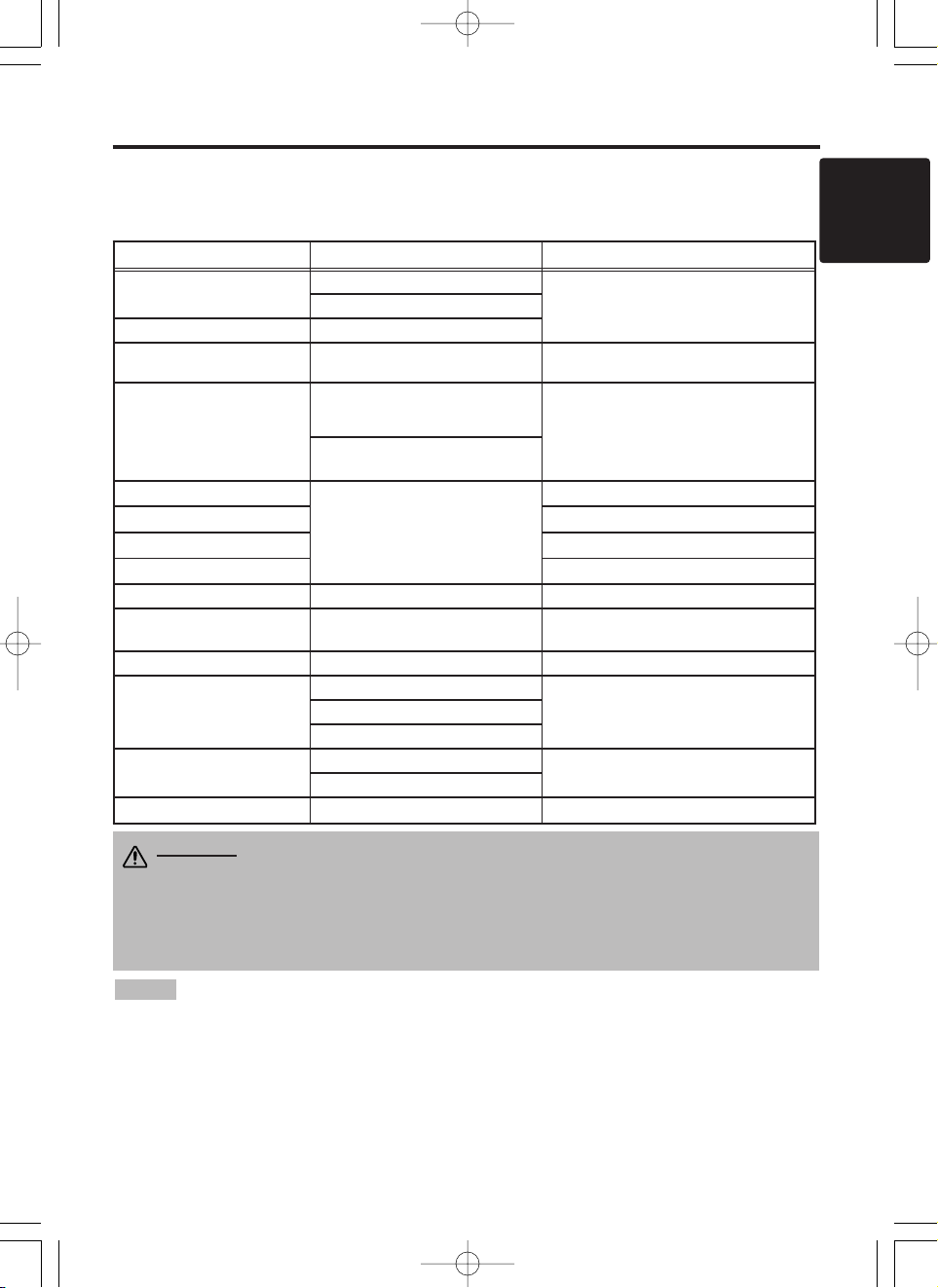
Cabling
Refer to the table below for connecting each terminal of the projector to a device.
Table 2. Cabling
Function Terminal Cable
Analog RGB input
RGB IN 1
Accessory RGB cable or optional RGB
cable with D-sub 15-pin shrink jack and
inch thread screws
RGB IN 2
Analog RGB output RGB OUT
Digital RGB input DIGITAL
Optional digital RGB cable with inch thread
screws
Audio input
(from the computer)
AUDIO IN [RGB 1] / [DIGITAL]
(interlocked with RGB IN 1 or
DIGITAL)
Optional audio cable with stereo mini jack
AUDIO IN [RGB 2]
(interlocked with RGB IN 2)
PS/2 mouse control
CONTROL
Accessory PS/2 mouse cable
ADB mouse control Optional ADB mouse cable
Serial mouse control Optional Serial mouse cable
RS-232C communication Optional RS-232C cable
USB mouse control USB Optional USB cable
S-video input S-VIDEO
Optional S-video cable with mini DIN 4-pin
jack
Video input VIDEO Accessory video/audio cable
Component video input
COMPONENT VIDEO Y
Accessory component video cableCOMPONENT VIDEO CB/PB
COMPONENT VIDEO CR/PR
Audio input
(from video equipment)
AUDIO (MONO)/L
Accessory video/audio cable or optional
audio cable with RCA jack
AUDIO R
Audio output AUDIO OUT Optional audio cable with stereo mini jack
01MP877501.4.139:52AMページ7
Page 8
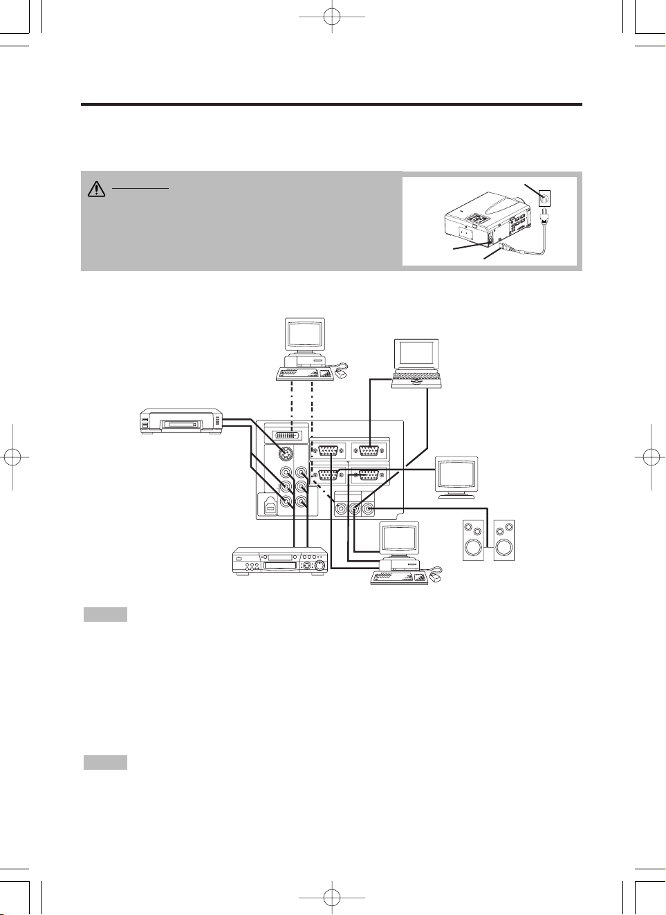
Example of system setup
S-Video Tape
Recorder
Computer (desktop type)
Computer
(notebook type)
• When connecting with a notebook computer, set the proper RGB external image output
(setting CRT display or simultaneous display of LCD and CRT). Please read instruction manual of
the notebook for more information.
Plug & Play
This projector is VESA DDC 1/2B compatible. Plug & play is possible by connecting to a computer
that is VESA DDC (Display Data Channel) compatible.
Please use this function by connecting the accessory RGB cable with RGB IN 1 terminal (DDC
1/2B compatible), or by connecting an optional digital RGB cable with DIGITAL terminal (DDC
2B compatible). Plug & play may not operate by other connections.
• Plug & play is a system configured with peripheral equipment including a computer,
display and an operating system.
• This projector is recognized as a plug & play monitor. Use the standard display drivers.
• Plug & play may not operate by the computer to connect. Plug & play will not operate in the
connection with Apple computer.
NOTE
NOTE
ENGLISH-8
IIIINNNNSSSSTTTTAAAALLLLLLLLAAAATTTTIIIIOOOONNNN ((((ccccoooonnnnttttiiiinnnnuuuueeeedddd))
))
Power Connection
Use the correct power cord depending on the power outlet to be used.
Connect the AC inlet of the projector to the power outlet firmly by the power cord.
AC Inlet
Power Cord
Power outlet
Speaker
with
amplifier
Display
Monitor
CAUTION • Be carful in handling the power
cord according to instructions of the
accompanying manual "Product Safety Guide"
and this manual.
• Connect the power cord firmly. Avoid using a
loose, unsound outlet or failed contact .
MP8775
P
O
R
T
A
B
L
E
P
R
O
J
E
C
T
O
R
Computer
(desktop type)
DVD Player
01MP877501.4.139:52AMページ8
S-VIDEO
(MONO)/L
USB
DIGTAL
RGB IN 2
COMPO
NENT
VIDEO
VIDEO
AUDIO
B/PB
C
R
CR/PR
RGB OUT
AUDIO IN AUDIO
RGB 2
RGB 1
DIGITAL
CONTROL
OUT
Page 9
ENGLISH-9
ENGLISH
ENGLISH-9
OPERATIONS
OPERATIONS
Power ON
1. Check that the power cord is connected correctly.
2. Set the power switch to [ | ]. The standby mode is selected, and the POWER indicator is turned to
orange.
3. Press the STANDBY/ON button on the control panel or the remote control transmitter.
Warm-up begins and the POWER indicator blinks in green.
4. The POWER indicator ceases blinking and turns to green when power is on. Remove the lens
cap.
5. Adjust picture size using the ZOOM button.
6. Adjust focus using the FOCUS button .
Power OFF
1. Press the STANDBY/ON button on the control panel or the remote control transmitter for
approximately two second. The projector lamp is extinguished and lamp cooling begins. The
POWER indicator blinks orange during lamp cooling. Pressing the STANDBY/ON button
has no effect while the POWER indicator is blinking.
2. The system assumes the Standby mode when cooling is complete, and the POWER indicator
ceases blinking and changes to orange. Check that the indicator is orange and set the Power
switch to [
O
].
3. The POWER indicator is extinguished when power is off. Attach the lens cap.
MP8775
P
O
R
T
A
B
L
E
P
R
O
J
E
C
T
O
R
M
P
8
7
7
5
+
Z
O
O
M
M
U
T
E
IN
P
U
T
S
T
A
N
D
B
Y
O
N
R
E
S
E
T
L
A
M
P
P
W
E
R
T
E
M
P
M
E
N
U
+
–
–
F
O
C
U
S
Power Switch
Lens cap
STANDBY/ON Button
POWER Indicator
STANDBY/ON
LASER
VIDEO
BLANK
RGB
AUTO
MENU
MENU SELECT
POSITION
RESET
FREEZE
MAGNIFY
PinP
OFF
VOLUME
MUTE
ZOOMFOCUS
STANDBY/
ON Button
ZOOM button
FOCUS button
• Except in emergencies, do not turn off unless the POWER indicator is orange as it will
reduce the life of the projector lamp.
• To prevent any troble, turn on/off the projector when the computer or video tape recorder is OFF.
Providing a RS-232C cable is connected, turn on the computer before the projector.
NOTE
WARNING
• Please read this manual, and the separate “Product Safety
Guide” thoroughly before using the equipment. Always ensure that the
equipment is used safely.
FOCUS button
ZOOM button
01MP877501.4.139:52AMページ9
Page 10

ENGLISH-10ENGLISH-10
OOOOPPPPEEEERRRRAAAATTTTIIIIOOOONNNNSSSS ((((ccccoooonnnnttttiiiinnnnuuuueeeedddd))
))
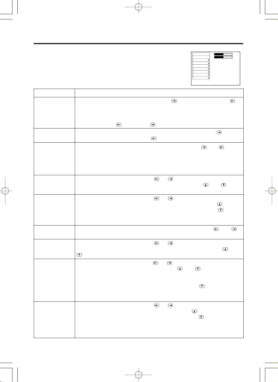
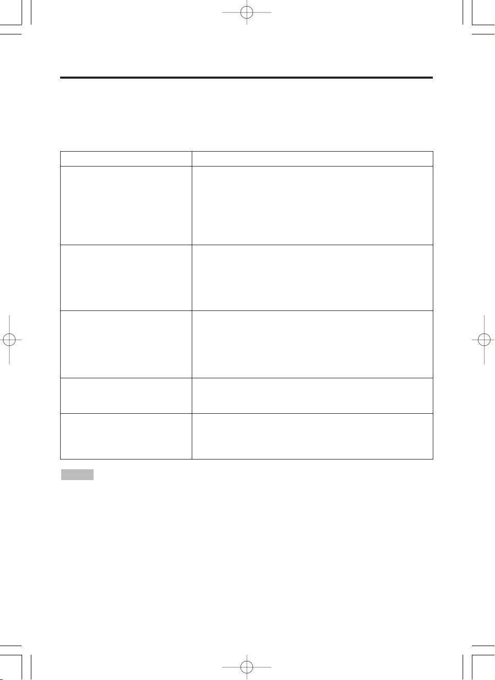
Basic Operation
The basic operations shown in Table 3 is performed from the supplied remote control transmitter or
the projector control panel. Items indicated by (*) may be used from the control panel.
Table 3 . Basic Operation
Item Description
INPUT
SELECT
Select Input Signal (*) : Press the INPUT button.
RGB IN 1 → RGB IN 2 → DIGITAL
→ VIDEO → S-VIDEO → COMPONENT VIDEO (→ RGB IN 1)
Select RGB Input : Press the RGB button.
VIDEO/S-VIDEO/COMPONENT VIDEO → RGB IN 1/RGB IN 2/DIGITAL
RGB IN 1 → RGB IN 2 → DIGITAL (→ RGB IN 1)
Select Video Input : Press the VIDEO button.
RGB IN 1/RGB IN 2/DIGITAL → VIDEO/S-VIDEO/COMPONENT VIDEO
VIDEO → S-VIDEO → COMPONENT VIDEO (→ VIDEO)
• The selected signal name is displayed for approximately 3 seconds when the input
signal is changed.
POSITION
Set/Clear Position Adjustment Mode : Press the POSITION button.
The [ ] icon is displayed in the POSITION mode.
Image Position Adjustment: Press the , , and buttons in the
POSITION mode.
• Valid only in the MAGNIFY mode with a video signal is input.
• After approximately 10 seconds of inactivity the [ ] icon is extinguished and the
POSITION mode is cleared automatically.
• , , and
buttons may operate as the mouse control button. Refer to page 4.
RESET (*)
Initialize Each Item : Select an item and press the RESET button.
Initialize Position Adjustment : Press the RESET button and the
POSITION mode. This function is valid only when RGB signal is input.
• Valid except for the VOLUME, LANGUAGE and H PHASE.
• The RESET button may operate as the mouse control button. Refer to page 4.
MAGNIFY
Set MAGNIFY Mode : Press the MAGNIFY button.
Move Magnified Area : Run the POSITION in the MAGNIFY mode.
Adjust Magnification : Press the MAGNIFY / button in MAGNIFY
mode.
Clear MAGNIFY Mode : Press the MAGNIFY button.
• The MAGNIFY mode is cleared by running or setting the AUTO, ASPECT, INPUT
SELECT or VIDEO, or by changing the input signal.
OFF
FREEZE
Set/Clear FREEZE Mode : Press the FREEZE button. The [II] icon is
displayed, and the image frozen, in the FREEZE mode.
• The FREEZE mode is cleared by running or setting POSITION, VOLUME, MUTE,
Automatic Adjustment, BLANK ON/OFF, or MENU ON/OFF, or by changing the input
signal.
• Do not forget to clear frozen static images.
• Use the remote control transmitter at a distance of approximately 5m from the sensor on
the front of the projector, and within a range of 30° left-right. Strong light and obstacles will
interfere with operation of the remote control transmitter.
NOTE
01MP877501.4.139:52AMページ10
Page 11

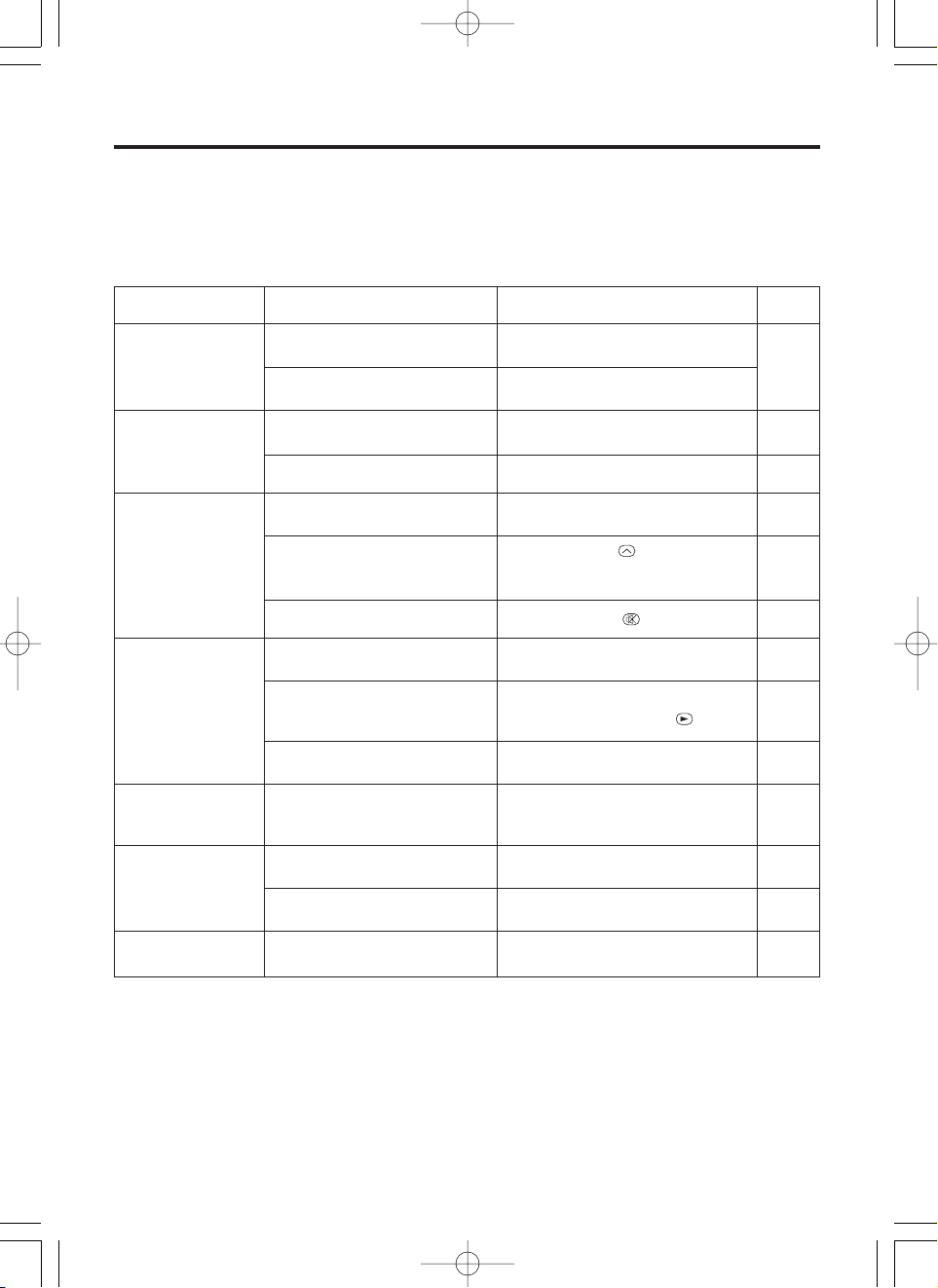
Item Description
VOLUME
Volume Adjustment : Press the VOLUME / button.
MUTE (*)
Set/Clear Mute Mode : Press the MUTE button. No sound is heard in the
MUTE mode.
AUTO
Automatic Adjustment at RGB Input : Press the AUTO button. Horizontal
position(H.POSIT), vertical position (V.POSIT),clock phase (H.PHASE), and
horizontal size(H.SIZE) are automatically adjusted. Use with the window at
maximum size in the application display.
Automatic Adjustment at Video Input : Press the AUTO button. A signal
type appropriate for the input signal is selected automatically. Valid only
when AUTO is set for VIDEO on the menu.
• This operation requires approximately ten seconds. It may not function correctly
with some input signals.
BLANK
ON/OFF
Set/Clear Blank Mode: Press the BLANK button. No image is displayed in
the Blank mode. The screen color is as set in BLANK on the Image menu.
MENU
ON/OFF (
*)
Menu Display Start/Stop: Press the MENU button.
• The menu display is terminated automatically after approximately ten seconds of
inactivity.
MENU
SELECT
Select Menu Type: Press the MENU SELECT button. Allows the user to
select the normal menu or the single menu. Only the selected item is
displayed on the single menu, and other items are displayed with the
and buttons as with the normal menu.
• Valid only when the Setup menu is used. Push the MENU SELECT button after
selecting items such as "BRIGHTNESS".
• The MENU SELECT button may operate as the mouse control button. Refer to
page 4.
Normal menu Single menu
P.IN P.
MODE
Select Mode of P.IN P. Display : Press the PinP button.
Small
→ Large → P.IN P. off (→Small)
• Valid only at RGB IN 1, RGB IN 2 or DIGITAL input.
ZOOM
Adjust Screen Size : Press the ZOOM / button.
FOCUS
Adjust Focus : Press the FOCUS / button.
ENGLISH-11
ENGLISH
ENGLISH-11
OOOOPPPPEEEERRRRAAAATTTTIIIIOOOONNNNSSSS ((((ccccoooonnnnttttiiiinnnnuuuueeeedddd))
))
Items indicated by (*) may be used from the control panel.
Table 3. Basic Operation (continued)
CONTRAST
-2
BRIGHT
CONTRAST
V POSIT
H POSIT
H PHASE
H SIZE
COLOR BAL R
COLOR BAL B
ASPECT
0
-2
+1
0
0
100
100
800
SETUP INPUT OPT.IMAGE
(MENU SELECT)
01MP877501.4.139:52AMページ11
Page 12

ENGLISH-12ENGLISH-12
OOOOPPPPEEEERRRRAAAATTTTIIIIOOOONNNNSSSS ((((ccccoooonnnnttttiiiinnnnuuuueeeedddd))
))
Setup Menu
The following adjustments and settings are possible
when SETUP is selected at the top of the menu. Part
of the Setup menu differs between RGB input and
video input. Select an item with the and
buttons, and start operation. Use the Single menu to
reduce menu size (see Table 3, MENU SELECT).
Table 4. Setup Menu
VIDEO
S-VIDEO
COMPONENT VIDEO
RGB IN 1
RGB IN 2
DIGITAL
BRIGHT
CONTRAST
V POSIT
H POSIT
H PHASE
H SIZE
COLOR BAL R
COLOR BAL B
ASPECT
0
-2
+1
0
0
100
100
800
SETUP INPUT OPT.IMAGE
BRIGHT
CONTRAST
SHARPNESS
COLOR
TINT
COLOR BAL R
COLOR BAL B
ASPECT
0
+1
+1
0
0
0
0
SETUP INPUT OPT.IMAGE
Item Description
RGB IN 1
RGB IN 2
DIGTAL
VIDEO
S-VIDEO
COMPONENT
BRIGHT
Adjustment: Dark ↔ Light
✔ ✔ ✔
CONTRAST
Adjustment: Weak ↔ Strong
✔ ✔ ✔
V POSIT
Adjustment: Down ↔ Up
✔
- -
H POSIT
Adjustment: Left ↔ Right
✔
- -
H PHASE
Adjustment: Left ↔ Right
• Adjust to eliminate flicker.
✔
- -
H SIZE
Adjustment: Small ↔ Large
• The image may not be displayed correctly if the horizontal
size is excessive. In such cases, press the RESET button,
and initialize the horizontal size.
✔
- -
SHARPNESS
Adjustment: Soft ↔ Clear
- -
✔
COLOR
Adjustment: Light ↔ Dark
- -
✔
TINT
Adjustment: Red ↔ Green
• Valid only when NTSC or NTSC 4.43 signal is received.
- -
✔
COLOR BAL R
Adjustment: Light ↔ Dark
✔ ✔ ✔
COLOR BAL B
Adjustment: Light ↔ Dark
✔ ✔ ✔
ASPECT
Select Image Aspect Ratio : 4:3[ ] ↔
16:9[ ]
Select Position of Image:
Press the button while 16:9[ ] is selected.
Center
→ Down → Up ( → Center )
✔ ✔
-
Select Image Aspect Ratio:
4:3[ ] ↔ 16:9[ ] ↔ 4:3 small[ ]
Select Position of Image :
Press the button while 16:9[ ] / 4:3 small[ ]
is selected.
Center
→ Down → Up ( → Center )
• 4:3 small may not be displayed correctly with some input
signals.
- -
✔
01MP877501.4.139:52AMページ12
Page 13

ENGLISH-13
ENGLISH
ENGLISH-13
OOOOPPPPEEEERRRRAAAATTTTIIIIOOOONNNNSSSS ((((ccccoooonnnnttttiiiinnnnuuuueeeedddd))
))
Input Menu
The following functions are available when INPUT is selected on the
menu. Select an item with the and buttons, and start or stop
operation with the and buttons. The function indicated (**) are
effective on video input mode only, not on RGB input mode, except in
the P.IN P. window on RGB input mode.
Table 5. Input Menu
EXECUTE
CANCEL
AUTO
RGB
VIDEO
VIDEO NR
Progressive
BLACK
SETUP INPUT OPT.IMAGE
Item Description
AUTO
Automatic Adjustment at RGB Input: Select the EXECUTE with the
button.
Horizontal position (H.POSIT), vertical position (V.POSIT), clock
phase (H.PHASE), and horizontal size (H.SIZE) are automatically adjusted.
Use with the window at maximum size in the application display.
Automatic Adjustment at Video Input: Select the
EXECUTE
with the
button. A signal type appropriate for the input signal is selected
automatically when
EXECUTE
is selected automatically. Valid only when
AUTO is set for VIDEO on the menu.
•
This operation requires approximately 10 seconds. It may not function correctly with
some input signals. Pressing the AUTO button in this case may correct this problem.
• This function is the same as for the AUTO function in Basic operation.
RGB
Displays RGB Input Frequency: Displays the horizontal and vertical sync
signal frequencies for RGB input.
• Valid only at RGB input.
VIDEO (**)
Select Video Signal Type: Select the signal type with the and
buttons. Select NTSC, PAL, SECAM, NTSC4.43, M-PAL, or N-PAL as
appropriate for the input signal. The selection of AUTO enables and
executes the function AUTO (Automatic Adjustment at Video Input), except
for the N-PAL input.
• Use this function when the image becomes unstable (eg. the image becomes
irregular, or lacks color) at VIDEO/S-VIDEO input.
• Automatic Adjustment requires approximately ten seconds. It may not function
correctly with some input signals. Pressing the AUTO button in this case may correct
this problem except for the N-PAL input.
• For the COMPONENT VIDEO input, this function is not effective and the signal type
is distinguished automatically. Refer to the item HDTV of the OPT. Menu for the
signal of HDTV.
VIDEO NR
(**)
Set/Clear Noise Reduction Mode: Select the TURN ON / TURN OFF with
the / button. When the TURN ON is selected, the NR mode is active
and the noise on screen of the video input will be reduced.
Progressive
(**)
Select Progressive Mode: Select the mode suitable for the input signal
with the and buttons. The TV mode and the CINEMA mode convert
the interlaced video signal into the progressive signal. The CINEMA mode is
adptable 2-3 Pull-Down system to the conversion.
• Use this function to raise resolution, at the interlaced video input except HDTV
signal.
BLACK(**)
Set/Clear Black Enhancement Mode: Select the TURN ON / TURN OFF
with the / button. When the TURN ON is selected, the black
enhancement mode is active and the contrast ratio of the screen for the
video input will be raised by making black level darker.
01MP877501.4.139:52AMページ13
Page 14

ENGLISH-14ENGLISH-14
OOOOPPPPEEEERRRRAAAATTTTIIIIOOOONNNNSSSS ((((ccccoooonnnnttttiiiinnnnuuuueeeedddd))
))
Image Menu
The following adjustments and settings are available when IMAGE is
selected on the menu. Select an item with the and buttons, and
start operation.
Table 6. Image Menu
KEYSTONE
BLANK
MIRROR
START UP
P. IN P.
+1
SETUP INPUT OPT.IMAGE
Item Description
KEYSTONE
Keystone Adjustment:
Reduce size of bottom of image ↔ Reduce size of top of image
• When this function is activated, the image may not be displayed correctly with
some input signals.
BLANK
Select Blank Screen Color: Select color with the and buttons.
• The image is cleared when the BLANK mode is set with BLANK ON, or when there
is no signal, and the entire screen is displayed in the selected color.
MIRROR
Operation Start/Stop: Press the or button.
Select Mirror Status: Select mirror status with and buttons.
START UP
Operation Start/Stop: Press the or button.
Setup Initial Screen Display: Select TURN ON with the button.
Clear Initial Screen Display: Select TURN OFF with the button.
• Note that if TURN OFF is selected the blank screen is displayed in blue when there
is no signal.
P. IN P.
Operation Start/Stop: Press the or button.
Select Position of P. in P. Display : Press the or button.
↔↔↔(↔)
• Valid only at RGB IN 1, RGB IN 2 or DIGITAL input.
01MP877501.4.139:52AMページ14
Page 15

ENGLISH-15
ENGLISH
ENGLISH-15
OOOOPPPPEEEERRRRAAAATTTTIIIIOOOONNNNSSSS ((((ccccoooonnnnttttiiiinnnnuuuueeeedddd))
))
Options Menu
The following adjustments and settings are available when OPT. is
selected on the menu. Select an item with the and buttons, and
start operation. The function indicated (**) are effective on video input
mode only, not on RGB input mode, except in the P.IN P. window on
RGB input mode.
Table 7. Options Menu
VOLUME
MENU COLOR
LANGUAGE
AUTO OFF
SYNC ON G
HDTV
16
SETUP INPUT OPT.IMAGE
Item Description
VOLUME
Volume Adjustment: Reduce VOLUME ↔ Increase VOLUME
MENU COLOR
Select Menu Background Color: Select with the and buttons.
LANGUAGE
Operation Start/Stop: Press the or button.
Select Menu Display Language: Select with the and buttons.
AUTO OFF
Operation Start/Stop: Press the or button.
Set AUTO OFF: Set 1~99 minutes with the and buttons. The
system automatically enters the standby mode when a signal is not
received for the set time.
Clear AUTO OFF: Select STOP (0 min.) with the button. When
STOP is selected the system does not enter the standby mode even if
no signal is received.
SYNC ON G
Operation Start/Stop: Press the or button.
SYNC ON G Valid: Select TURN ON with the button.
SYNC ON G Invalid: Select TURN OFF with the button.
• May not be displayed correctly with some input signals when SYNC ON G is
valid. In such cases, remove the signal connector so that no signal is received,
set SYNC ON G to invalid, and reconnect the signal.
HDTV (**)
Select HDTV mode: Select the 1035i mode or 1080i mode suitable for
the input signal with the / button.
01MP877501.4.139:52AMページ15
Page 16
ENGLISH-16ENGLISH-16
OOOOPPPPEEEERRRRAAAATTTTIIIIOOOONNNNSSSS ((((ccccoooonnnnttttiiiinnnnuuuueeeedddd))
))
No Signal Menu
The same adjustments and settings are available with the Image and
Options menus when the MENU button is pressed during display of the
“NO INPUT IS DETECTED ON ***” or “SYNC IS OUT OF RANGE
ON ***” message while no signal is received.
Table 8. No Signal Menu
VOLUME
KEYSTONE
BLANK
MIRROR
START UP
MENU COLOR
LANGUAGE
AUTO OFF
SYNC ON G
16
+1
Item Description
VOLUME
Volume Adjustment: Reduce VOLUME ↔ Increase VOLUME
• When this function is used, audio input is automatically switched to video. The
audio input can be switched by moving the DISK PAD left and right during the
display of the volume adjustment bar. The volume adjustment bar is displayed by
pressing VOLUME or VOLUME button.
KEYSTONE
Keystone Adjustment: Reduce the size of bottom of image ↔
Reduce the size of top of image
BLANK
Select Blank Screen Color: Select the color with the and
buttons.
• When the blank mode is set with BLANK ON, by absence of a signal, or by
input of a non-standard signal, the image is cleared and the complete screen is
displayed in the selected color.
MIRROR
Operation Start/Stop: Press the or button.
Select Mirror Status: Select the mirror status with the and
buttons.
START UP
Operation Start/Stop: Press the or button.
Setup Initial Screen Display: Select the TURN ON with the button.
Clear Initial Screen Display: Select the TURN OFF with the button.
• Note that if TURN OFF is selected the blank screen is displayed in blue when
there is no signal.
MENU COLOR
Select Menu Background Color: Select the color with the and
buttons.
LANGUAGE
Operation Start/Stop: Press the or button.
Select Menu Display Language: Select the language with the and
buttons.
AUTO OFF
Operation start/stop: Press the or button.
Set AUTO OFF: Set 1~99 minutes with the and buttons. The
system automatically enters the standby mode when a signal is not
received for the set time.
Clear AUTO OFF: Select the STOP (0 min.) with the button. When
the STOP is selected the system does not enter the standby mode even
if no signal is received.
SYNC ON G
Operation Start/Stop: Press the or button.
SYNC ON G Valid: Select the TURN ON with the button.
SYNC ON G Invalid: Select the TURN OFF with the button.
• May not be displayed correctly with some input signals when the SYNC ON G
is valid. In such cases, remove the signal connector so that no signal is received,
set the SYNC ON G to invalid, and reconnect the signal.
01MP877501.4.139:52AMページ16
Page 17
ENGLISH-17
ENGLISH
ENGLISH-17
MAINTENANCE
MAINTENANCE
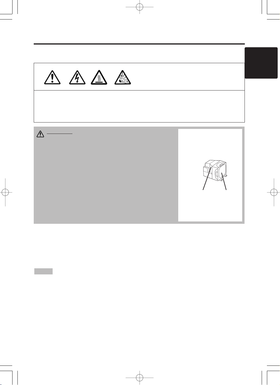
Lamp
HIGH VOLTAGE
HIGH TEMPERATURE
HIGH PRESSURE
Contact your dealer before replacing the lamp.
For the optional lamp, see the item “Option Parts” of the Table 12.
Before replacing the lamp, switch power OFF, remove the power cord from the power outlet, and
wait approximately 45 minutes until the lamp has cooled. The lamp may explode if handled at high
temperatures.
Lamp Life
Projector lamps have a finite life. The image will become darker, and hues will become weaker,
after a lamp has been used for a long period of time.
Replace the lamp if the LAMP indicator is red, or the CHANGE THE LAMP message appears
when the projector is switched ON. See Table 9 of P.20 and Table 10 of P.21.
• The LAMP indicator is also red when the lamp unit reaches high temperature. Before
replacing the lamp, switch power OFF, wait approximately 20 minutes, and switch power ON again.
If the LAMP indicator is still red, replace the lamp.
NOTE
Lamp
Front
glasss
Reflector
WARNING • For disposal of used lamp, treat
according to the instruction of community
authorities.
• Since the lamp is made of glass, do not apply shock
to it and do not scratch it.
• Also, do not use old lamp. This could also cause
explosion of the lamp.
• If it is probable that the lamp has exploded (explosive
sound is heard), disconnect the power plug from the
power outlet and ask your dealer to replace lamp. The
lamp is covered by front glass , but, in rare cases, the
reflector and the inside of the projector may be
damaged by scattered broken pieces of glass, and
broken pieces could cause injury when being handled.
• Do not use the projector with the lamp cover removed.
01MP877501.4.139:52AMページ17
Page 18
ENGLISH-18ENGLISH-18
MMMMAAAAIIIINNNNTTTTEEEENNNNAAAANNNNCCCCEEEE ((((ccccoooonnnnttttiiiinnnnuuuueeeedddd))
))
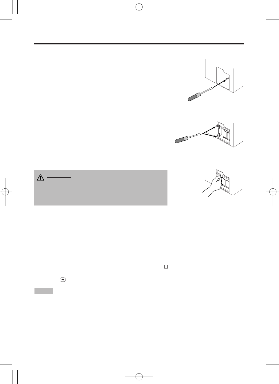
Replacing the Lamp
1. Switch the projector OFF, remove the power cord from the
power outlet, and wait at least 45 minutes for the unit to cool.
2. Prepare a new lamp.
3. Check that the projector has cooled sufficiently, and gently
turn it upside down.
4. Loosen the screw as shown in the diagram, and remove the
lamp cover.
5. Loosen the two screws, and gently remove the lamp while
holding the grips. Touching the inside of the lamp case may
result in uneven coloring.
6. Install the new lamp and tighten the two screws firmly. Also
steadily push the opposite side of the screwed lamp into the
unit.
7. Replace the lamp cover in position and tighten the screw
firmly.
8. Gently turn the projector right-side up.
Resetting the Lamp Timer
Reset the lamp timer after replacing the lamp. When the lamp has been replaced after the LAMP
indicator is red, or the CHANGE THE LAMP message is displayed, complete the following
operation within ten minutes of switching power ON. The power will be turned off automatically in
over 10 minutes.
1. Switch power ON, and press the RESET button, for approximately three seconds. The ‘LAMP
xxxx hr’ message will appear on the lamp timer on the bottom of the screen.
2. Press the MENU button on the remote control transmitter, or the RESET button on the control
panel, while the lamp timer is displayed. The ‘LAMP xxxx
→ 0 ■ CANCEL’ message will
then appear.
3. Press the and select 0, and wait until the timer display is cleared.
• Do not reset the lamp timer without replacing the lamp. Reset the lamp timer always
when replacing the lamp. The message functions will not operate properly if the lamp timer is not
reset correctly.
NOTE
CAUTION • Ensure that screws are tightened
properly. Screws not tightened fully may result
in injury or accidents.
• Do not use the projector with the lamp cover
removed.
01MP877501.4.139:52AMページ18
Page 19
ENGLISH-19
ENGLISH
ENGLISH-19
MMMMAAAAIIIINNNNTTTTEEEENNNNAAAANNNNCCCCEEEE ((((ccccoooonnnnttttiiiinnnnuuuueeeedddd))
))
Air Filter Maintenance
The air filter should be cleaned as described below at intervals of approximately 100 hours.
1. Switch the projector power supply OFF, and remove the power cord from the power outlet.
2. Clean the air filter with a vacuum cleaner.
Other Maintenance
Maintenance Inside the Equipment
For safety reasons, ensure that the equipment is cleaned and checked by the dealer once every two
years. Maintaining the equipment by yourself is dangerous.
Cleaning the Lens
Gently wipe the lens with lens cleaning paper. Do not touch the lens with your hands.
Cleaning the Cabinet and Remote control transmitter
Gently wipe with a soft cloth. If dirt and stains etc. are not easily removed, use a soft cloth
dampened with water, or water and a neutral detergent, and wipe dry with a soft, dry cloth.
CAUTION • Switch power OFF and remove the power cord from the power
outlet before beginning maintenance work. Please read the separate “Product
Safety Guide” thoroughly to ensure that maintenance is performed correctly.
• Do not use detergents or chemicals other than those noted above (e.g. benzene
or thinners).
• Do not use cleaning sprays.
• Do not rub with hard materials, or tap the equipment.
CAUTION • Switch power OFF and remove the power cord from the power
outlet before beginning maintenance work. Please read the separate “Product
Safety Guide” thoroughly to ensure that maintenance is performed correctly.
• Replace the air filter if contamination cannot be removed, or if it is damaged.
Contact your dealer in such case. For the optional air filter, see the item “Optional
Parts” of the Table 12.
• Do not use the equipment with the air filter removed.
• When the air filter is clogged with dust etc. the power supply is switched OFF
automatically to prevent the temperature rising inside the projector.
01MP877501.4.139:52AMページ19
Page 20
ENGLISH-20ENGLISH-20
TROUBLESHOOTING
TROUBLESHOOTING
OSD Message
The messages as described below may appear on the screen at power ON. Take the appropriate
measures when such messages appears.
Table 9. OSD Messages
Message Contents
CHANGE THE LAMP
AFTER REPLACING LAMP,
RESET THE LAMP TIME.
*1)
The message shown at left appears after the lamp has
been used for more than 1300 hours.
The lamp is approaching the end of its life.
Power is switched OFF automatically when the lamp
reaches the end of its life. Prepare a new lamp for
installation.
Always reset the lamp timer after replacing the lamp.
CHANGE THE LAMP
AFTER REPLACING LAMP,
RESET THE LAMP TIME.
THE POWER WILL TURN OFF
AFTER ** hr.
*1)
The lamp will reach the end of its life in ** hours.
Power will be switched OFF automatically in
** hours.
Replace the lamp as shown in P.17~18 “Lamp”.
Always reset the lamp timer after replacing the lamp.
CHANGE THE LAMP
AFTER REPLACING LAMP,
RESET THE LAMP TIME.
THE POWER WILL
TURN OFF
AFTER 0 hr.
The lamp has reached the end of its life. Power will be
switched OFF in a few minutes.
Switch power OFF immediately and replace the lamp as
shown in P.17~18 “Lamp”.
Always reset the lamp timer after replacing the lamp.
NO INPUT IS DETECTED
ON ***
No input signal found.
Check signal input connections and signal sources.
SYNC IS OUT OF RANGE
ON ***
The horizontal or vertical frequency of the input signal is
not within the specified range.
Check the specifications of the equipment and the signal
source.
*1) This message is cleared automatically after approximately three minutes, and appears
every time power is switched ON.
NOTE
01MP877501.4.139:52AMページ20
Page 21

ENGLISH-21
ENGLISH
ENGLISH-21
TTTTRRRROOOOUUUUBBBBLLLLEEEESSSSHHHHOOOOOOOOTTTTIIIINNNNGGGG ((((ccccoooonnnnttttiiiinnnnuuuueeeedddd))
))
Indicators Message
The POWER indicator, LAMP indicator, and TEMP indicator are lit and blank as follows. Take the
appropriate measures.
Table 10. Indicators Message
POWER
indicator
LAMP
indicator
TEMP
indicator
Contents
Lights
orange
Turns off Turns off The Standby mode has been set.
Blinks
green
Turns off Turns off Warming up. Please wait.
Lights
green
Turns off Turns off ON. Normal operation possible.
Blinks
orange
Turns off Turns off Cooling. Please wait.
Lights red
Lights
red
Turns off
Lamp is not lit.
The interior of the equipment may be too hot. Switch
power OFF, wait 20 minutes until the equipment cools,
and check whether the ventilation openings are blocked,
whether the air filter is dirty, or whether the ambient
temperature exceeds 35 °C. And switch power ON
again. Replace the lamp if the same problem occurs.
Lights red
Blinks
red
Turns off
Lamp or lamp cover is not found, or hasn’t been fitted in
correctly.
Switch power OFF, and wait for 45 minutes until the
equipment cools. Check fitting of the lamp and lamp
cover, and switch power ON again. Contact your dealer if
the same problem occurs again.
Lights red Turns off
Blinks
red
The cooling fan is not operating.
Switch power OFF, and wait for 20 minutes until the
equipment cools. Check for foreign matters in the fan,
and switch power ON again. Contact your dealer if the
same problem occurs again.
*1) When the internal temperature becomes excessive power is switched OFF
automatically for safety reasons, and the indicator is extinguished. Set the power switch to [
O
] and
wait for 20 minutes until the equipment has cooled sufficiently.
NOTE
01MP877501.4.139:52AMページ21
Page 22
ENGLISH-22ENGLISH-22
TTTTRRRROOOOUUUUBBBBLLLLEEEESSSSHHHHOOOOOOOOTTTTIIIINNNNGGGG ((((ccccoooonnnnttttiiiinnnnuuuueeeedddd))
))
Symptom
Before requesting repair, check in accordance with the following chart. If the situation cannot be
corrected, then contact your dealer.
Table 11. Symptom
Symptom Possible cause Remedy Page
The power is not
turned on.
The main power switch is not
turned on.
Turn on the main power switch.
8,9
The power cord is
disconnected.
Plug the power cord into an AC
power outlet.
No video or audio.
The input is not correctly set.
Use the projector or remote control
transmitter to set.
10
No signal input. Connect correctly.
7,8
Video is present but
no audio.
The projector is not correctly
connected.
Connect correctly.
7,8
The volume is set to minimum.
Press VOLUME on the remote
control or display the menu screen
and adjust the volume.
11,15
Mute is turned on.
Press the MUTE button.
11
Audio is present but
no video.
The projector is not correctly
connected.
Connect correctly.
7,8
The brightness adjustment knob
is rotated fully clockwise.
Select BRIGHT with the MENU
button and the press the button.
12
The lens cap is still attached. Remove the lens cap.
9
Colors are pale and
color matching is
poor.
Color density and color
matching are not correctly
adjusted.
Adjust the video.
12
Images are dark.
Brightness and contrast are not
correctly adjusted.
Adjust the video.
12
The lamp is nearing the end of
its service life.
Replace with a new lamp.
17
Video is blurred.
Focus or H PHASE is out of
adjustment.
Adjust the focus or H PHASE.
9,12
01MP877501.4.139:52AMページ22
Page 23
ENGLISH-23
ENGLISH
ENGLISH-23
SPECIFICATIONS
SPECIFICATIONS
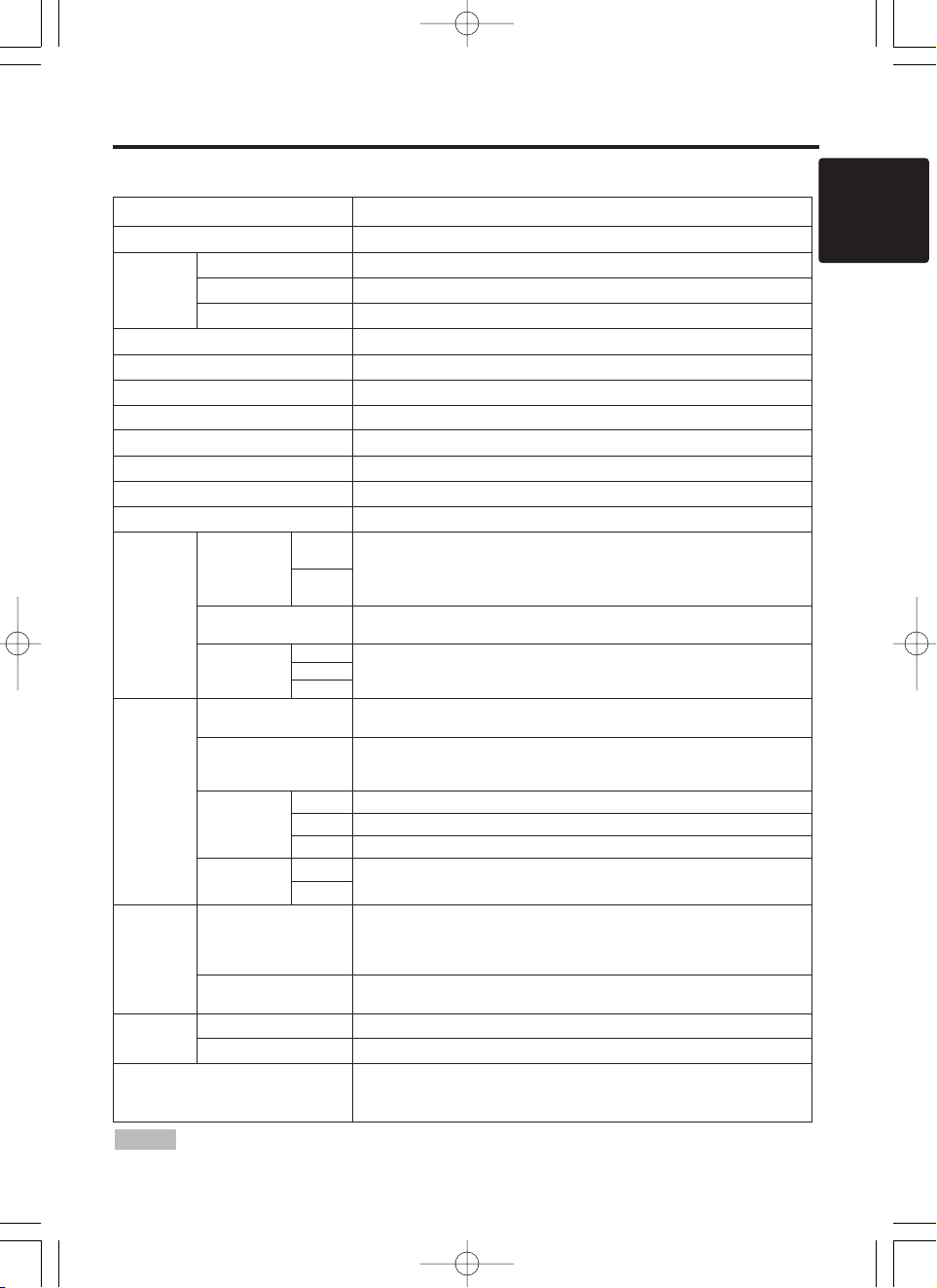
Table 12. Specifications
• This specifications are subject to change without notice.
NOTE
Item Specification
Product name Liquid crystal projector
Liquid
crystal
panel
Panel size 3.3 cm (1.3 type)
Drive system TFT active matrix
Pixels 786,432 pixels (1024 horizontal x 768 vertical)
Lens Zoom lens F=1.7 ~ 2.3 f=49.0 ~ 64.0 mm
Lamp 250 W UHB
Speaker 1.2 W + 1.2W (Stereo)
Power supply AC100 ~ 120V, 4.5A / AC220 ~ 240V, 2.2A
Power consumption 400W
Temperature range 0 ~ 35°C (Operating)
Size 289 (W) x 124 (H) x 350 (D) mm
Weight (mass) 6.4 kg
RGB
signal
input
RGB IN
1
Video: Analog 0.7Vp-p, 75Ω terminator (positive)
H/V. sync.: TTL level (positive/negative)
Composite sync.: TTL level
D-sub 15-pin shrink jack
2
DIGITAL
TMDS, DC: 150~1200 mV / AC: 1.56 Vp-p
TTL Level (Positive/Negative)
AUDIO IN
RGB1
200mVrms, 50 kΩ (max. 3.0Vp-p)
Stereo mini jack
DIGITAL
RGB2
Video
signal
input
VIDEO
1.0Vp-p, 75Ω terminator
RCA jack
S-VIDEO
Brightness signal: 1.0Vp-p, 75Ω terminator
Color signal: 0.286Vp-p (burst signal), 75Ω terminator
Mini DIN 4-pin jack
COMPONENT
VIDEO
Y 1.0 Vp-p, 75 Ω Terminator (Positive)
CB/CR 0.7 Vp-p, 75 Ω Terminator (Positive)
PB/PR 1.0 Vp-p, 75 Ω Terminator (Positive)
AUDIO
L
200mVrms, 50 kΩ (max. 3.0Vp-p)
RCA jack
R
Signal
output
RGB OUT
Video: Analog 0.7Vp-p, 75Ω output impedance (positive)
H/V. sync.: TTL level (positive/negative)
Composite sync.: TTL level
D-sub 15-pin shrink jack
AUDIO OUT
200mVrms, output impedance 1 kΩ (max. 3.0Vp-p)
Stereo mini jack
Control
functions
CONTROL D-sub 15-pin shrink plug
USB USB jack (B type)
Optional Parts
Lamp: DT00341
Air Filter: MU0832
* For others, consult your dealer.
01MP877501.4.139:52AMページ23
Page 24
Important Notice
All statements, technical information, and recommendations related to 3M’s products are based on information
believed to be reliable, but the accuracy or completeness is not guaranteed. Before using this product, you must
evaluate it and determine if it is suitable for your intended application. You assume all risks and liability
associated with such use. Any statements related to the product which are not contained in 3M’s current
publications, or any contrary statements contained on your purchase order shall have no force or effect unless
expressly set forth in a written agreement signed by an authorized officer of 3M.
Warranty and Limited Remedy. This product will be free from defects in material and manufacture for a
period of two years from the date of purchase. Exclusion to Warranty: The lamps are considered a consumable
item and are warrantied for 90 days or 180 hours, whichever occurs first. 3M MAKES NO OTHER
WARRANTIES, INCLUDING BUT NOT LIMITED TO, ANY IMPLIED WARRANTY OF
MERCHANTABILITY OR FITNESS FOR A PARTICULAR PURPOSE. If this product is defective within
the warranty period stated above, your exclusive remedy shall be, at 3M’s option, to replace or repair the 3M
product or refund the purchase price of the 3M product.
Limitation of Liability. Except where prohibited by law, 3M will not be liable for any loss or damage
arising from this 3M product, whether direct, indirect, special, incidental or consequential regardless of
the legal theory asserted.
Let us help you make the most of your next presentation. We offer everything from presentation supplies to tips
for better meetings. And we’re the only transparency manufacturer that offers a recycling program for your used
transparencies. For late-breaking news, handy reference and free product samples, call us toll-free in the
continental United States and Canada, 24 hours a day, or visit our Internet Website.
3M Austin Center
Building A145-5N-01
6801 River Place Blvd.
Austin, TX 78726-9000
3M Canada
P.O. Box 5757
London, Ontario
N6A 4T1
3M Mexico, S.A. de C.V.
Apartado Postal 14-139
Mexico, D.F. 07000
Mexico
3M Europe
Boulevard de l’Oise
95006 Cerge Pontoise Cedex
France
Litho in Japan
Copyright © 2001 3M IPC.
All Rights Reserved
01MP877501.4.139:52AMページ24
 Loading...