

Page 1

MP8610 Multimedia Projector
Operator’s Guide
Projecteur multimédia MP8610 Guide d’utilisation
MP8610 Multimedia-Projektor Bedienerhandbuch
Proyector de medios múltiples (multimedia) MP8610 Guía del operador
Guida dell’operatore del proiettore multimediale MP8610
Bruksanvisning för MP8610 Multimediaprojektor
3M MP8610 Multimediaprojector Gebruiksaanwijzing
MP8610
8610-03A
___________________________________________________________
i
Page 2

Page 3

Table of Contents
SAFEGUARDS
I
NTENDED USE
I
MPORTANT SAFEGUARDS
S
AVE THESE INSTRUCTIONS
WARRANTY
IMITED WARRANTY
L
IMITATION O F LIABILITY
L
SECTION 1: UNPACK
ONTENTS OF SHIPPING BOX
1-1. C
NVENTORY LIST
1-2. I
EEP YOUR PACKING MATERIALS
1-3. K
1-4. W
HAT’S NEXT
SECTION 2: PRODUCT DESCRIPTION
2-1. M
2-2. P
ACHINE CHARACTERISTICS
ARTS IDENTIFICATION LIST
SECTION 3: QUICK SET UP
ROJECTOR SET UP
3-1. P
ABLE CONNECTIONS
3-2. C
ROJECTOR TERMINAL CONNECTIONS
3-3. P
ONTROL PANEL KEYPAD
3-4. C
3-5. M
3-6. I
OUSE CONNECTION
MAGE SIZE (PROJECTOR-TO-SCREEN DISTANCE
.............................................................................................................................................................1
...........................................................................................................................................1
.......................................................................................................................................1
....................................................................................................................................................2
.............................................................................................................................................2
................................................................................................................................3
..................................................................................................................................................3
.......................................................................................................................3
?.................................................................................................................................................... 3
...............................................................................................................................4
.................................................................................................................................4
..............................................................................................................................................5
..........................................................................................................................................5
....................................................................................................................................6
...........................................................................................................................................6
.................................................................................................................6
)................................................................................................6
SECTION 4: OPERATING INSTRUCTIONS
ROJECTOR START UP
4-1. P
TANDBY MODE
4-2. S
ROJECTOR POWER DOWN
4-3. P
SING SYSTEM MENUS
4-4. U
4-5. M
ENU ADJUSTMENTS/SETTINGS
..........................................................................................................................................7
...................................................................................................................................................7
...................................................................................................................................8
........................................................................................................................................8
...........................................................................................................................9
SECTION 5: REMOTE CONTROL
OW TO OPERATE THE REMOTE CONTROL
5-1. H
EPLACING THE BATTERIES
5-2. R
EMOTE CONTROL BUTTON FUNCTIONS
5-3. R
................................................................................................................................10
.........................................................................................................10
............................................................................................................11
SECTION 6: LAMP INFORMATION
6-1. M
6-2. L
6-3. R
ETAL HALIDE PROJECTION LAMP
AMP LIFE INDICATOR
EPLACING THE LAMP
.......................................................................................................................................12
.........................................................................................................................................13
....................................................................................................................12
SECTION 7: MAINTENANCE
EPLACING THE AIR FILTER
7-1. R
LEANING THE PROJECTOR
7-2. C
...............................................................................................................................15
................................................................................................................................16
SECTION 8: TROUBLESHOOTING
ROUBLESHOOTING PROBLEMS
8-1. T
ERVICE INFORMATION
8-2. S
......................................................................................................................................18
..........................................................................................................................17
___________________________________________________________
i
Page 4

Table of Contents, continued
APPENDIX
ECHNICAL SPECIFICATIONS
A-1. T
HYSICAL DIMENSIONS
A-2. P
ROJECTOR-TO-SCREEN DISTANCE
A-3. P
ROJECTOR-TO-SCREEN DISTANCE, CONTINUED
A-3. P
B-1. S–V
C-1. S
C-2. F
D-1. A
D-2. H
D-3. P
IDEO INPUT SIGNAL TERMINAL
ETTING REPRESENTATION
ACTORY DEFAULT SETTINGS
CCESSORY PARTS LIST
OW TO ORDER
OWER CORD SETS
..................................................................................................................................................27
............................................................................................................................................28
GLOSSARY
LOSSARY OF TERMS
G
.................................................................................................................................................29
INDEX
NDEX
.........................................................................................................................................................................31
I
..............................................................................................................................19
......................................................................................................................................20
....................................................................................................................20
................................................................................................21
....................................................................................................................22
ESOLUTION
, R
..........................................................................................................23
............................................................................................................................25
.....................................................................................................................................26
___________________________________________________________
ii
Page 5

Safeguard s
INTENDED USE
Before operating the machine, please read the entire manual thoroughly. The 3M Multimedia Projector
MP8610 was designed, built and tested for use indoors, using 3M brand lamps, 3M brand ceiling
mount hardware and
different voltages has not been tested and could damage the projector or peripheral equipment and/or
create a potentially unsafe operating condition.
nominal local
IMPORTANT SAFEGUARDS
1. Read and understand all instructions before using. Pay particular attention to areas where this symbol
!
is shown.
!
WARNIN
WARNING
in death or serious injury.
-
voltages. The use of other replacement lamps, outdoor operation or
Indicates a potentially hazardous situation which, if not avoided, could result
!
Caution
minor or moderate injury. It may also be used to alert against unsafe practices.
9 Note
2. Close supervision is necessary when any appliance is used by or near children. Do not leave
appliance unattended while in use.
3. Never look directly into the projector lens when the lamp is on. The metal halide lamp produces a
strong light that could damage your eyesight.
!
4. Care must be taken as burns can occur from touching hot parts.
5. Do not operate appliance with a damaged cord or if the appliance has been dropped or damaged - until
it has been examined by a qualified service technician.
!
6. Position the cord so that it will not be tripped over, pulled or contact hot surfaces.
7. If an extension cord is necessary, a cord with an earth/ground and a current rating at least equal to that
of the appliance should be used. Cords rated for less amperage than the appliance may overheat.
8. Always unplug appliance from electrical outlet before cleaning and servicing and when not in use.
Grasp plug and pull to disconnect.
9. To reduce the risk of electric shock, do not immerse this appliance in water or other liquids.
10. To reduce the risk of electric shock, do not disassemble this appliance, but take it to a qualified
technician when service or repair work is required. Incorrect reassembly can cause electric shock
when the appliance is subsequently used.
11. The use of an accessory attachment not recommended by the manufacturer may cause a risk of fire,
electric shock, or injury to persons.
12. Connect this appliance to a grounded outlet.
!
13. This unit is equipped with optical lenses and should not be exposed to direct sunlight.
14. Keep ventilation openings free of any obstructions.
15. Always operate machine on a flat, sturdy surface.
16. The projection lamp contains mercury. Always dispose of it in a proper manner according to local
regulations.
17. To avoid premature lamp failure, do not change the mounting position of the projector (desktop ⇒
ceiling mount or ceiling mount ⇒ desktop mount) and continue to use the same lamp.
–
-
Indicates a potentially hazardous situation which, if not avoided, could result in
Used to emphasis important conditions or details.
SAVE THESE INSTRUCTIONS
The information contained in this manual will help you operate and maintain your 3M MP8610 Multimedia
Projector.
3M 1998 3M Multimedia Projector MP8610 1
Page 6

Warranty
LIMITED WARRANTY
3M warrants this product against any defects in material and workmanship, under normal use and
storage, for a period of one year from date of purchase. Proof of purchase date will be required with any
warranty claim. In the event this product is found to be defective within the warranty period, 3M’s only
obligation and your exclusive remedy shall be replacement of any defective parts (labor included).
To obtain warranty service, immediately notify the dealer from which you purchased the product of any
defects. In the USA call 1–800–328–1371 for warranty or repair service.
LIMITATION OF LIABILITY
THE FOREGOING WARRANTY IS MADE IN LIEU OF ALL OTHER WARRANTIES, EXPRESSED OR IMPLIED,
AND 3M SPECIFICALLY DISCLAIMS ANY IMPLIED WARRANTY OF MERCHANTABILITY AND FITNESS FOR A
PARTICULAR PURPOSE. 3M SHALL NOT BE LIABLE FOR ANY DAMAGES, DIRECT, CONSEQUENTIAL, OR
INCIDENTAL, ARISING OUT OF THE USE OR INABILITY TO USE THIS PRODUCT.
Important:
3M’s written instructions. This warranty gives you specific legal rights and you may have other rights
that vary from state to state.
The above warranty shall be void if the customer fails to operate product in accordance with
REGULATORY NOTICES
FCC STATEMENT - CLASS A:
energy, and if not installed and used in accordance with the instruction manual may cause interference to
radio communications. It has been tested and found to comply with the limits for a Class “A” computing
device pursuant to Subpart B of Part 15 of the FCC Rules, which are designed to provide reasonable
protection against such interference when operated in a commercial environment. Operation of this
equipment in a residential area is likely to cause interference in which case the user at his/her own
expense will be required to take whatever measures may be required to correct the interference.
EEC STATEMENT:
Community) for EMC (Electro Magnetic Compatibility) and fulfills these requirements.
Video signal cables:
Video inputs:
The input signal amplitude must not exceed the specified level. See Appendix A-1.
This machine was tested against the 89/336/EEC (European Economic
Only use cables delivered by the manufacturer.
This equipment generates, uses and can radiate radio frequency
PATENT/COPYRIGHT INFORMATION
and
IBM
Macintosh
trademark of the Microsoft Corporation. All other products are trademarks or registered trademarks of
their respective companies.
23M Multimedia Projector MP8610 3M 1998
are registered trademarks of
PS/2
and
are registered trademarks of
ADB
International Business Machines Corporation
Apple Computer, Inc
.
Microsoft Windows
.
Apple
is a
Page 7

Section 1: Unpack
1-1. Contents of Shipping Box
The 3M
Multimedia Projector MP8610 is shipped with the necessary cables required for standard
VCR, PC or laptop computer connections. Carefully unpack and verify that you have all of the items
shown below.
9 Note
A set of cables for connection to Apple Macintosh is
available as an option. See Appendix D-1.
1-2. Inventory List
The shipping carton contains the following items illustrated in Figure 1–1. If any of these items are
missing, please contact your place of purchase.
1. MP8610 Multimedia Projector
2. Remote control transmitter
(AAA batteries included)
3. VGA cable 15-15 pin male to male)
4. Mouse cable (9–9 pin female to female)
5. Power cord set (U.S., UK, and European)
For special power cords see Appendix D-3
VIDEO AUX
PC
MENU
ENTER
1 2 3
4 5 6
789
REVEAL BLANK
TIMER
0
OPTIMIZE
VOL BRIGHT
FREEZE
MOUSE
MP8610
1
POINTER MAGNIFY
23 4 5
6. PS/2 mouse adapter
7. Audio cable (RCA–mini jack)
8. S-video cable
9. RCA video cable
10. Operator’s Guide (not shown)
6789
8610-10A
Figure 1-1. Inventory of Shipping Box
1-3. Keep Your Packing Materials
Save the shipping box and packing materials in the event the MP8610 should require shipping to a 3M
Service Center for repair. U
se packing material to protect projector.
1-4. What’s Next?
After you have unpacked the MP8610 system and identified all the parts, you are ready to set up the
projector. Take a few minutes to review Section 2 to familiarize yourself with the MP8610 machine
characteristics and then turn to Section 3 to set up the projector
We hope you will enjoy using this high performance product in your meetings, presentations and training
sessions. This product has been produced in accordance with 3M’s highest quality and safety standards
to ensure smooth and trouble-free use in the years to come.
3M 1998 3M Multimedia Projector MP8610 3
.
Page 8

Section 2: Pr oduct Description
2-1. Machine Characteristics
The 3M
Multimedia Projector MP8610 integrates metal halide lamp and single amorphous silicon
TFT LCD technology. It accepts input from a computer source and two video/audio sources and projects
a bright super crisp image with perfect color convergence.
The MP8610 Multimedia Projector offers the following features:
Easy to set up and use
•
Metal halide projection lamp 400W
•
High brightness lamp output (
•
SVGA (800 x 600) resolution
•
XGA (1024 x 768) compression
•
VGA (640 x 480) expansion
•
NTSC, PAL, SECAM, S-VHS video
•
Ability to display 16.7 million colors
•
One computer input connection
•
Built-in MS, PS/2 and ADB mouse
•
emulation
Two video/audio input connections
•
see note
)
Variable focus
•
Full function remote control
•
Built–in stereo speakers
•
Horizontal and vertical image inverting
•
function allows rear screen and ceiling
mounted projection
On–screen menu for easy projector set up
•
Menus display in English, French,
•
Spanish, Italian, Dutch, Swedish, German
Fixed keystone correction
•
A slot for a Kensington Lock
•
Mounting holes for optional document
•
camera
VIDEO AUX
PC
MENU
1
10
ENTER
1 2 3
4 5 6
789
REVEAL BLANK
TIMER
0
OPTIMIZE
VOL BRIGHT
FREEZE
MOUSE
POINTER MAGNIFY
2
6
MP8610
5
3
Figure 2-1. Identifying MP8610 Parts
2-2. Parts Identification List
1. Remote Control Transmitter
2. Lens
3. Remote Control Sensor
4. Built–In Speakers (stereo)
5. Height Adjustment Feet
6. Foot Release Button
11
9
7
4
8
8610-07A
7. Power Cord Connection
8. Input Terminals
9. Main Power Switch
10. Control Panel Keypad
11. Slot for Kensington Lock
43M Multimedia Projector MP8610 3M 1998
Page 9

Section 3: Quick Set U
p
3-1. Projector Set Up
The Quick Set Up instructions are intended to get you going in a hurry. If you have any difficulty, refer
to Appendix C-1.
!
Caution
To prevent
MP8610 and input sources must be turned OFF during
cable hook up.
damage to equipment
, all power to
1. Place the projector on a rigid, non–slip
surface.
2. Connect the power cord. (Section 3–2).
3. Connect the audio and video input cables to
the projector-input terminals. (Section 3–
2).
4. For mouse emulation, connect the mouse
cable. (Section 3–5).
adapter is necessary for Apple Macintosh
computers. See Appendix D-1.)
(An additional
3-2. Cable Connections
It only takes a few minutes to connect the 3M
or other video device (Figure 3-1).
5. Power up the projector then the computer
and the video sources. (Section 4–1).
6. Move the projector nearer or further away
from the screen to obtain the best image size
(Section 3-6).
Multimedia Projector MP8610 to your computer, VCR
1. Power Cord
2. Computer
3. Mouse Emulation
a) MS Mouse Port
b) PS/2 Mouse Port
4. S-VHS
5. VCR
Figure 3-1. Typical Cable Configuration
1. Turn off all power to the projector and input sources during cable hook up.
2. Connect cables being careful not to bend any pins in the cable connector plug or on the
computer/input terminals.
3. Start up projector then start up input sources. Section 4–1.
3M 1998 3M Multimedia Projector MP8610 5
Page 10

3-3. Projector Terminal Connections
Take a moment to look over the input terminals (Figure 3–2) on the back of the projector. Terminal
connectors for the computer source are: RGB, Mouse, Audio 1/Audio 2. Terminal connectors for the
video sources are: Video, S–Video, Audio 1/Audio 2.
1. ON/OFF power switch.
2. Power cord terminal
3. RGB Computer terminal
4. Mouse terminal
5. Audio 1-3.5 mm stereo mini jack (Data)
6. Video jack
7. S-VHS jack
8. Audio 2-3.5 mm stereo mini jack (VCR)
Figure 3-2. Input Connection Terminals
3-4. Control Panel Keypad
The control panel keypad (Figure 3-3) is located on the back of the projector. It has the following
buttons:
1. Green indicator lamp
2. Red indicator lamp
3. Standby button
4. Menu button.
5. Enter button.
6. Arrow Keys (up/down, left/right)
Figure 3-3. Control Panel Keypad
3-5. Mouse Connection
The projector has a built-in mouse emulation capability. Use the mouse cable (9-9 pin female-to-female,
shipped with the projector) to connect your computer to the projector. Then control your computer
mouse functions via the remote control.
1. Power down the computer and projector.
2. Remove the mouse cable connection from
your computer mouse port.
Connect the mouse port of the projector to
3.
the mouse port of the computer. Use the
mouse cable and PS/2 adapter (if required)
supplied with this projector.
adapter is necessary for Apple Macintosh
computers. See Appendix D-1.)
(An additional
4. First, power on the projector, then power on
the computer.
9 Note
Mouse emulation only works, when all cable
connections are established and then the proper
start up sequence is followed. See section 4–1.
3-6. Image Size (Projector-to-Screen Distance)
Adjust the size of the projected image on the screen by moving the projector closer to the screen for a
smaller image size or further away from the screen for a larger image size. See Appendix A-3.
63M Multimedia Projector MP8610 3M 1998
Page 11

Section 4: Operating Instructions
4-1. Projector Start Up
Read the Important Safeguards before operating the MP8610 projector. After all cable connections have
been completed, the projector can be powered up. For best results, please observe the following start up
sequence. Refer to Figure 4-1
!
Caution
Allow a projector that has been stored in a cold place
to warm up to room temperature before applying
power.
1. Press the power switch
power to the projector (| = ON, O = OFF).
The
2. Press the Standby button
LED
appear and grow brighter on the screen.
3. Check all ventilation slots and clear away
any obstructions.
4. Turn the lens
5. Press the foot lock button
height adjustment feet.
6. Raise/lower projector body to extend or
retract feet
Rotate feet
7. Power up your computer source and video
source(s).
LED
red
will illuminate and an image will
(3)
will illuminate.
(3)
to focus the image.
(4)
to obtain best image height.
(6)
for fine adjustment.
(7)
9
In most cases, the projector will automatically adjust
to the graphic mode of your computer by selecting a
pre–programmed setting. See Appendix C-2.
to ON to apply
(1)
(2)
(5)
Note
. The
green
to release the
2
1
5
6
Figure 4-1. Projector Setup
3
MP8610
4
7
8610-11A
4-2. Standby Mode
When the projector is not being used, place it into standby mode.
1. Press the Standby button.
2. The lamp will switch off and the
will illuminate.
3. Press the standby button again to illuminate
the lamp and project an image on the screen.
3M 1998 3M Multimedia Projector MP8610 7
red
LED
9
Note
In standby mode, the fan motor will continue to run
for a few minutes until the projector cools down.
Page 12
4-3. Projector Power Down
y
g
p
p
Press the Standby button to place the projector in the standby mode. The cooling fan motor will continue
to run.
9 Note
Switching the power off b efore the fan has cycled
off, will decrease the life of the projection lamp.
1. Wait until the cooling fan motor cycles off then press the main power switch to Off.
2. Turn off the power to your input devices.
3. To transport the projector, disconnect the power cord, computer cable, mouse cable and audio/video
cables.
Fully retract the projection lens to protect it during transport.
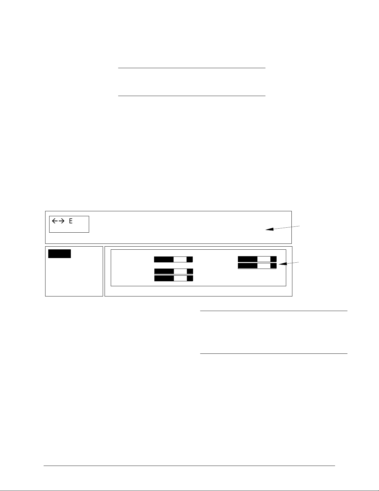
4-4. Using System Menus
You can use the control panel buttons (Figure 3-3) or the remote control (Figure 5-1) to access menus,
exit menus and set menu options. At the top of each menu is a
help window,
that pertain to the menu item that is highlighted.
Press the up/down or left/right ARROW KEYS on the control panel or move the DISC PAD on the
remote to navigate through the
submenus
and select menu items.
which displays messages
ÅÆ
Enter
Menu clear menu
Setup
Option
Audio
Data
for setup sub
menu
VESA 800 x 600 60 Hz
nc Brightness
S
Trackin
H. off. Inverse off
V. off. Pix. 800x600
-+
1056 Contrast
-+
-+
1. Press the MENU button to display the main
menu.
2. Press the up/down ARROW KEYS or move
the DISC PAD up/down to choose a submenu.
3. Press the ENTER button to select the sub–
menu.
4. Press the up/down ARROW KEYS or move
DISC PAD to select a menu item in the submenu.
5. Press the left/right ARROW KEYS or move
the DISC PAD left/right to change the value
of a menu item.
6. Press the ENTER button, if required, to
confirm the change to the menu item.
Hel
Window
-+
-+
9
Note
When the background of the displayed item turns
red, you must press the
the change.
ENTER
Setu
Submenu
button to confirm
7. Press the MENU button to exit the submenu and return to the main menu.
8. In some cases, a message will display in the
help window asking you to confirm the
changes made in the sub-menu. Press
ENTER to confirm.
9. Press the MENU button to exit the main
menu display and return to the projected
image.
83M Multimedia Projector MP8610 3M 1998
Page 13

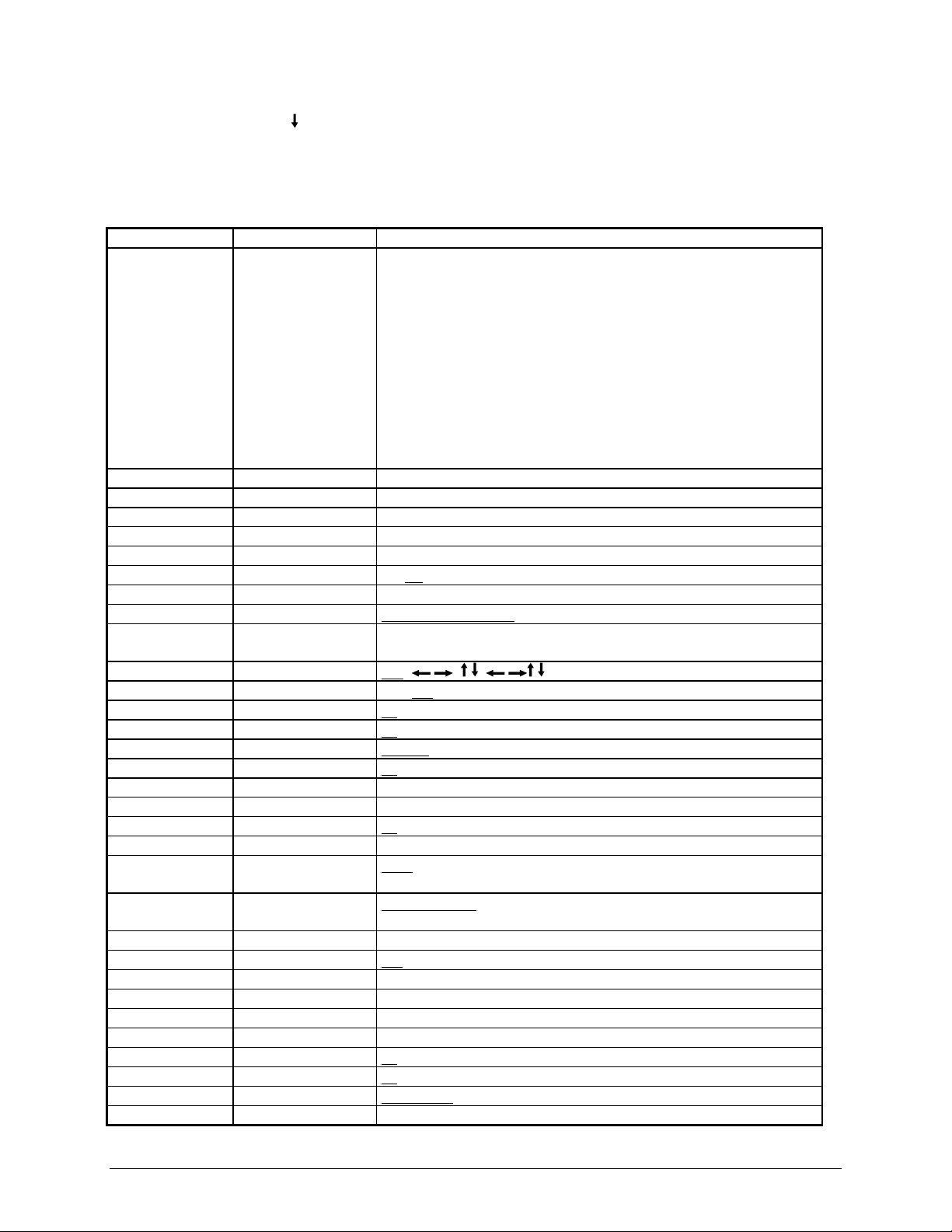
4-5. Menu Adjustments/Settings
Depending on the current video source selection, the menu items for either the Video Menu or the Data
Menu will display. The table below lists all the menu items that can be adjusted.
An asterisk (*) indicates the item appears on the Data menu only, two asterisks (**) indicate the item
appears on the Video/S-VHS menu only and no marking ( ) indicates the item is common to both menus.
Submenu Menu Item Explanation of Adjustment/Setting
Setup*/Picture** <Mode>* Selection of graphic mode (e.g. VGA 640 x 480, VESA 800 x
600 72 Hz, etc.). Five user modes. See Appendix C-2.
Brightness Image brightness.
Contrast Image contrast.
V. off.* (vertical offset) Adjusts the vertical position of the image.
H. off.* (horizontal offset) Adjusts the horizontal position of the image.
Color** Color saturation.
Inverse* Inverse image displayed.
Sync*
Tracking*
Pix.* Image format. (For unscaled image use 800 x 600)
Option Projection Change image direction for rear, ceiling mount, rear ceiling
Lamp Mode Select lamp power: eco. (low), std. (high) (
Remote Turn remote control feature On/Off.
Auto Mode* Turn automatic mode detection On/Off.
Language Select menu display language.
Help Turn menu help text messages On/Off.
Std.** Selection of video standard (Default = Auto)
Lamp* Lamp life indicator. Green bar - lamp is good. Red bar -
Sog* Sync-On-Green level. Only for Sync-On-Green mode.
Deinterlacing** On = standard video input (VCR)
Reset Restores video modes to factory default settings.
<Sync Mode>* Change synchronization mode (separate, composite, Sog).
Hue** Color level for NTSC video.
NTSC** Default setting of NTSC image (scaled or unscaled)
Audio Volume Volume level.
Treble Treble setting.
Bass Bass setting.
Balance Left/right balance of speakers.
Audio Speakers On/Off.
Stereo Stereo sound On/Off.
<Audio assignment> Select audio-in channels (Audio-1/Audio-2) to speakers
<Video Mode> Select video source: Data, Video or S-VHS
Manual
synchronization (phase) or
using Enter.
Manual
screen width (total pixel number/line) or
adjustment using Enter.
mount and normal projection.
lamp needs replacement.
Off = motion video input (camera)
(Default = On)
according to video selection.
Audio-In 1: Data S-VHS S-VHS
Audio-In 2: Video Data Video
(Default=off)
(Default=std.)
(Default=English)
(Default = On)
automatic
(Default=On)
adjustment
automatic
Default = eco.)
(Default=On)
(Default = On)
(Default=Data/Video)
3M 1998 3M Multimedia Projector MP8610 9
Page 14

Section 5: Remote Control
5-1. How to Operate the Remote Control
The remote control keypad (Figure 5–3) controls basic projector functions. To use the remote control,
aim the remote toward the projection screen and press the desired button. The remote signal (Figure 5-1)
will bounce off of the projection screen and back to the sensor on the front of the projector.
MP8610
8610-12A
Figure 5-1. Remote Control Signal
5-2. Replacing the Batteries
The remote control uses two AAA batteries. The battery cover is located on the back of the remote
control (Figure 5-3).
1. Press the locking tab
2. Lift up on the door
3. Remove old batteries.
4. Install new batteries
battery compartment.
5. Replace battery compartment door.
to release the battery compartment door.
(1)
to remove it and set it to the side.
(2)
making sure the polarity (+/-) on each battery matches the decal in the
(3)
3
2
+
–
–
+
+
+
–
–
1
8610-06A
Figure 5-2. Replacing Batteries
10 3M Multimedia Projector MP8610 3M 1998
Page 15

5-3. Remote Control Button Functions
Remote Button Description of Button Function
Press to switch the projector between Standby
mode (lamp off, fan off) and operation mode (lamp
on, fan on).
PC
VIDEO
AUX
MENU
DISC PAD
Switches to PC mode.
Switches to video mode. When in video mode, the
video source can be selected (Video or S-Video) by
pressing the key repeatedly.
Not used
Start the On Screen Menu System for projector
adjustment.
Mouse emulation ON
, disc pad controls the
movement of the pointing device.
Emulation OFF
, disc pad centers image on screen.
PC
VIDEO AUX
MENU
L/ENTER
R
1-6
REVEAL/7
BLANK/8
TIMER/9
OPTIMIZE
VOL
BRIGHT
MOUSE
POINTER
MAGNIFY
FREEZE
Mouse emulation ON, left mouse button. Mouse
emulation OFF, Enter button for confirmation of a
selection.
Right mouse button, when mouse-emulation active.
Not used.
Press REVEAL to cover the image on the screen
with a gray mask. Use the disc pad to reveal the
image or press REVEAL again to return full screen
projection of image.
Removes projected image, white background.
Press again to return projection image.
When the key is operated the timer-window appears
in the lower part of the display. Repeated operation
of the key switches over to full image display of the
timer and back to data projection. The timer starts
with the last used adjustment. A new start value is
entered by operating the key ENTER and adjusting
the value with the disc pad. Operating the ENTER
key again starts the timer. When the timer has run
down, the timer window blinks repeatedly.
Optimize (adjust) brightness and contrast settings
for best picture.
Volume adjustment.
Mute.
Brightness adjustment.
Press ON/Off to activate/deactivate mouse
emulation capability.
ON: The L and R buttons operate the left and right
mouse key functions. Drag-and-drop functions are
possible by simultaneous operation of the L/R
mouse key and disc pad.
OFF: L button is the Enter confirmation key.
R button not used. Disc pad centers image.
Places a pointing device on the screen. Move
pointer by operating the disc pad.
Press MAGNIFY to double the image size in
horizontal and vertical direction. The details of the
middle of the picture can be seen. Move the disc
pad to displace the magnified area within the image.
Press the MAGNIFY key again to switch back to
normal presentation.
In Video mode
, press MAGNIFY to switch between
scaled and unscaled representation. This is only for
NTSC video.
Stores (freezes) the projected image. Press
FREEZE again to return the projection of the
current image.
ENTER
L
1 2 3
4 5 6
789
REVEAL
BLANK
0
OPTIMIZE
VOL BRIGHT
MOUSE
POINTER MAGNIFY
Figure 5-3. Remote Control
R
TIMER
FREEZE
8610-05aA
3M 1998 3M Multimedia Projector MP8610 11
Page 16

Section 6: Lamp Information
6-1. Metal Halide Projection Lamp
The metal halide lamp of the projector has a limited life time (approximately 2000 hours). If the
projected image appears dark or a
should change the lamp and air filter.
This lamp contains mercury
hazardous waste regulations and
lamp in a proper manner.
6-2. Lamp Life Indicator
lamp life indicator bar displays during projector startup, you
red
9 Important Note
. Consult your local
dispose of this
The elapsed operating time of the lamp can be checked in the
menu item
After changing the projection lamp, the lamp life indicator must be reset to zero.
To reset the lamp life indicator:
1. Select the menu item
2. Follow the instructions in the help window.
3. Press
ENTER
is green, the lamp is good. When the bar changes to red, the lamp should be changed.
Lamp
in the
Lamp
and the arrow of the projector control panel for confirmation.
Option
menu and press
Option
ENTER.
menu. As long as the bar of the
12 3M Multimedia Projector MP8610 3M 1998
Page 17

6-3. Replacing the Lamp
!
Caution
Always unplug the projector when changing the
lamp. There are high voltage parts inside the
cabinet that may
cause electric shock
.
Allow the projector to cool down for 30 minutes.
Lamp and adjacent metal parts become
extremely hot and can cause
fingers.
!
Caution
burns to your
1. Press the Standby button on the projector control panel or remote control and wait for the fan
motor to cycle off.
2. Turn off the power switch and unplug the projector power cord.
3. Stand the projector upright on the left side with the bottom facing you (see figure 6-1).
4. Locate the lamp access door
5. Remove the two screws
(2)
6. Push down on the lock tab
7. Slide the door open
and remove it.
(4)
on the bottom of the projector.
(1)
.
to release the door.
(3)
4
3
2
1
8610-13A
Figure 6-1. Removing Lamp Door
8. Press the tab
9. Carefully lower the lamp assembly
to release the lamp assembly (see figure 6-2).
(5)
to access the metal halide lamp.
(6)
10. The lamp is double ended with sockets on both sides. Carefully pull upward on both ends of the lamp
to remove it.
(7)
Figure 6-2. Lower Lamp Assembly
3M 1998 3M Multimedia Projector MP8610 13
Page 18

11. Install the new lamp (3M Lamp Kit Part Number 78-6969-8577-5) by pushing down on the ends of
the lamp
with equal pressure. Take care to correctly align the lamp with the bubble
(8)
(8a)
facing
upward (see figure 6-3).
9 Important Note
Do not touch lamp glass with fingers. Hold lamp by
the metal ends only.
12. Fold the lamp housing
13. Insert the lamp access door
14. Insert the two screws
into the closed position until the lock tab
(6)
and slide it closed to engage the lock tab
(1)
.
(2)
Figure 6-3. Replacing the Lamp
15. Replace the air filter (included in the lamp kit). See Section 7-1.
secures it.
(5)
(3)
.
9 Important Note
Always change the air filter when the lamp is
replaced. When you order a metal halide lamp, it
comes in a kit which includes an air filter.
14 3M Multimedia Projector MP8610 3M 1998
Page 19

Section 7: M ain ten an ce
7-1. Replacing The Air Filter
For best performance, replace the air filter each time the projection lamp is changed. One air filter is
included in each lamp kit
(
3M Part Number 78-8118-3476-7
(3M Part Number 78-6969-8577-5)
). See Appendix D-1.
9 Note
Periodically check air filter for excess dust or dirt.
Replace or clean as needed.
1. Unplug the power cord of the projector.
2. Stand the projector upright on the left side with the bottom facing you.
3. Locate the air filter door
4. Push the lock tab
to release the door.
(2)
on the bottom of the projector.
(1)
or air filters are available individually as
2
1
Figure 7-1. Removing Air Filter Door
5. The air filter door has a plastic hook
on one end. Use this hook to reach inside the projector and
(4)
hook the corresponding tab on the air filter frame.
6. Remove the air filter
by pulling straight outward.
(5)
7. Insert the new air filter by sliding it into position.
Insert the air filter door and press the lock tab to secure it in place.
8.
3
8610-14A
Figure 7-2. Replacing Air Filter
3M 1998 3M Multimedia ProjectorMP8610 15
Page 20
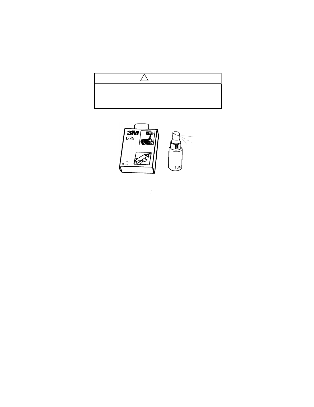
7-2. Cleaning the Projector
For best performance, keep your projector free of excess dust and surface dirt.
Use a soft cloth to remove dust from the projector housing. Use 3M Overhead Cleaner 676 to remove
surface dirt and smudges from the projection lens (Figure 7-3).
!
Caution
Always unplug the projector when cleaning. Take care
that no liquids get inside the projector. There are high
voltage parts inside the cabinet that may
electric shock
.
cause
Figure 7-3. Overhead Cleaner
16 3M Multimedia Projector MP8610 3M 1998
Page 21

Section 8: Tr ou b lesh ootin g
8-1. Troubleshooting Problems
The MP8610 has been designed to be as simple and as trouble free to use as possible. If you run into
problems when using the MP8610, consult the following chart.
Problem Probable Cause Possible Solution
Image is disturbed or
unstable.
No computer image
projected. Message
No input detected
shown.
No video image
projected.
Mouse does not work.
Image off-center.
Cannot get entire
image on the screen.
Washed out image.
Humming noise.
Slowly passing
horizontal bars.
No power
Power shuts off
during presentation
is
•
Wrong
•
Wrong
value.
• Loose cable.
• No power to computer.
•
Wrong synchronization
mode.
•
Loose cable.
• N o signal from video
source.
• Loose cable.
•
Wrong connection.
• Wrong power up
sequence.
•
Image position.
•
Wrong
value.
• Compatibility
problem.
•
Wrong
• Wrong
setting.
•
Wrong
setting.
•
Signal sources are
connected to different
power sources.
• VCR connected to
aerial system and to
projector
• Bad signal.
•
Power switch off.
• Projector overheated.
setting.
Sync
Tracking
Tracking
setting.
Pixel
Contrast
Brightness
.
•
Set to
factory default setting
• Change
performance (refer to Appendix C-1).
• For vertical interference stripes, change the
the
Setup
Appendix C-1).
• Check and secure cable connections.
• Turn on computer.
•
Adjust synchronization mode of the projector to the
synchronization mode of the co mpute r via
•
Check and secure cable connections.
• Check video picture on TV.
• Check and secure cable connections.
•
For PS/2 and ADB (Apple) mouse a special adapter is
necessary. Only use adapters from the original
manufacturer (refer to section 3-5.).
• The mouse emulation operates correctly only if the correct
power up sequence has been used (refer to section 3-5.)
•
Center image with the arrow keys of the control panel or
the disc pad on the remote control.
•
If vertical interference stripes occur, change the Tracking
value in the Setup menu for optimum performance.
• Refer to the documentation of your graphic card. The
projector supports the resolutions that can be found under
in the
Pixel
• Adjust the
resolution of the video mode output from the computer
graphic card.
• Change
should be in the middle position.
•
Lower
adjustment can be performed by choosing
pressing
•
Locate the source of disturbance. Disconnect the sources
one after another from the projector. Connect all sources to
a common power source.
• Re move antenna connection from VCR. If the disturbance
disappears, use a by-pass filter (isolating transformer) to
connect the antenna to the VCR.
• Try different input source.
•
Turn on power switch to projector.
• Remove any obj ects blocking ventilation and allow
projector to cool down. Power will return and projector
will be in Standby mode.
setting in the
Sync
menu for optimum performance (refer to
menu (refer to Appendix C-2).
Setup
setting in the
Pixel
Contrast
Brightness
Enter
setting in the
setting in the Setup menu. An automatic
.
(refer to Appendix C-2).
menu for optimum
Setup
Tracking
Option
menu to the
Setup
menu. The bar
Setup
Brightness
in
menu.
and
3M 1998 3M Multimedia ProjectorMP8610 17
Page 22

8-2. Service Information
For product information, product assistance, service information, or to order accessories, please call:
In U.S. or Canada:
In other locations, contact your local 3M Sales office.
1–800–328–1371
18 3M Multimedia Projector MP8610 3M 1998
Page 23

Appendix A: Technical Specifications
A-1. Technical Specifications
Rated voltage 100 - 120 V~ 50/60Hz
220 - 240 V~ 50/60Hz
Power consumption 500W (typical)
Power supply 3-wire grounded, AC 90-132VAC, 50/60 Hz
AC 198-264VAC, 50/60 Hz
Width 280 mm (11 in.)
Height 178 mm (7 in.)
Depth 440 mm (17.3 in.)
Weight 6.0 kg (13.4 lb.)
Panel aSi 6.4 in. TFT, 800 x 600 x 3 pixel
Number of pixels per panel 480,000 pixels (H800 x V600 x RGB = 1.44 million pixels)
Storage temperature range
Operating temperature
range
Optical structure Fresnel - wide angle, F5.6 lens
Lens 165 mm f/5 fixed focus lens, manual focus
Keystone correction 16° fixed
Brightness 500 lumens
Input terminals RGB (w/ separate sync, composite sync or sync on green):
Input signals
Color 16.7 million.
Contrast 200:1
Internal Speakers 2 x 10 W, stereo
Batteries for remote control Two AAA, 1.5 Volt
Regulatory Approvals FCC Part 15, Class A, CE, UL
Warranty One year limited warranty on parts and labor
-20°C to 60°C (-4°F to 140°F)
0°C to 35°C (32°F to 95°F)
DSub 15 pin
Serial (RS232) out to computer: (DSub 9 pin)
Video: (RCA jack)
S–Video: (Mini DIN 4–pin)
2 x Audio In: Stereo, 3.5 mm headphone jack
RGB 0.7V peak-to-peak, 75Ω termination, w/ TTL or analog Sync
Video: 1.0V peak–to–peak, 75Ω termination
S–Video: Luminance 1.0V peak–to–peak , 75Ω termination Chroma
0.286V peak–to–peak (burst signal) 75Ω termination
Audio: 0.7 Vrms, across 30
Max pixel rate: 75 MHz (typical)
κΩ
3M 1998 3M Multimedia ProjectorMP8610 19
Page 24

A-2. Physical Dimensions
The MP8610 projector has the following physical dimensions:
MP8610
440 mm
(17.3 in.)
178 mm
(7 in.)
280 mm
(11 in.)
8610-04A
A-3. Projector-to-Screen Distance
The following table shows the image size relative to the distance of the projector from the screen. This
distance is measured from the front of the projector lens to the screen.
DISTANCE TO SCREEN
(feet)
Diagonal Width Height
4.5 ft. 54 in. 43 in. 32 in.
5.0 ft 60 in. 48 in. 36 in.
5.5 ft 64 in. 51 in. 38 in.
6.0 ft 75 in. 60 in. 45 in.
6.5 ft 79 in. 63 in. 47 in.
7.0 ft. 87 in. 70 in. 52 in.
7.5 ft. 94 in. 75 in. 56 in.
8.0 ft. 100 in. 80 in. 60 in.
8.5 ft. 108 in. 86 in. 65 in.
9.0 ft. 114 in. 91 in. 68 in.
10.0 ft 128 in. 102 in. 77 in.
11.0 ft. 140 in. 112 in. 84 in.
12.0 ft 154 in. 123 in. 92 in.
IMAGE SIZE
(inches)
20 3M Multimedia Projector MP8610 3M 1998
Page 25

A-3. Projector-to-Screen Distance, continued
The following table shows the image size, relative to the distance of the projector from the screen. This
distance is measured from the front of the projector lens to the screen.
DISTANCE TO SCREEN
(cm)
125 cm 126 cm 100 cm 76 cm
150 cm 150 cm 119 cm 90 cm
175 cm 175 cm 139 cm 105 cm
200 cm 205 cm 164 cm 123 cm
225 cm 229 cm 183 cm 137 cm
250 cm 263 cm 210 cm 158 cm
275 cm 290 cm 232 cm 174 cm
300 cm 321 cm 257 cm 193 cm
325 cm 340 cm 272 cm 204 cm
350 cm 375 cm 300 cm 225 cm
375 cm 400 cm 320 cm 240 cm
400 cm 429 cm 343 cm 257 cm
IMAGE SIZE
(cm)
Diagonal Width Height
3M 1998 3M Multimedia ProjectorMP8610 21
Page 26
Appendix B: Compatibility/Video Standards
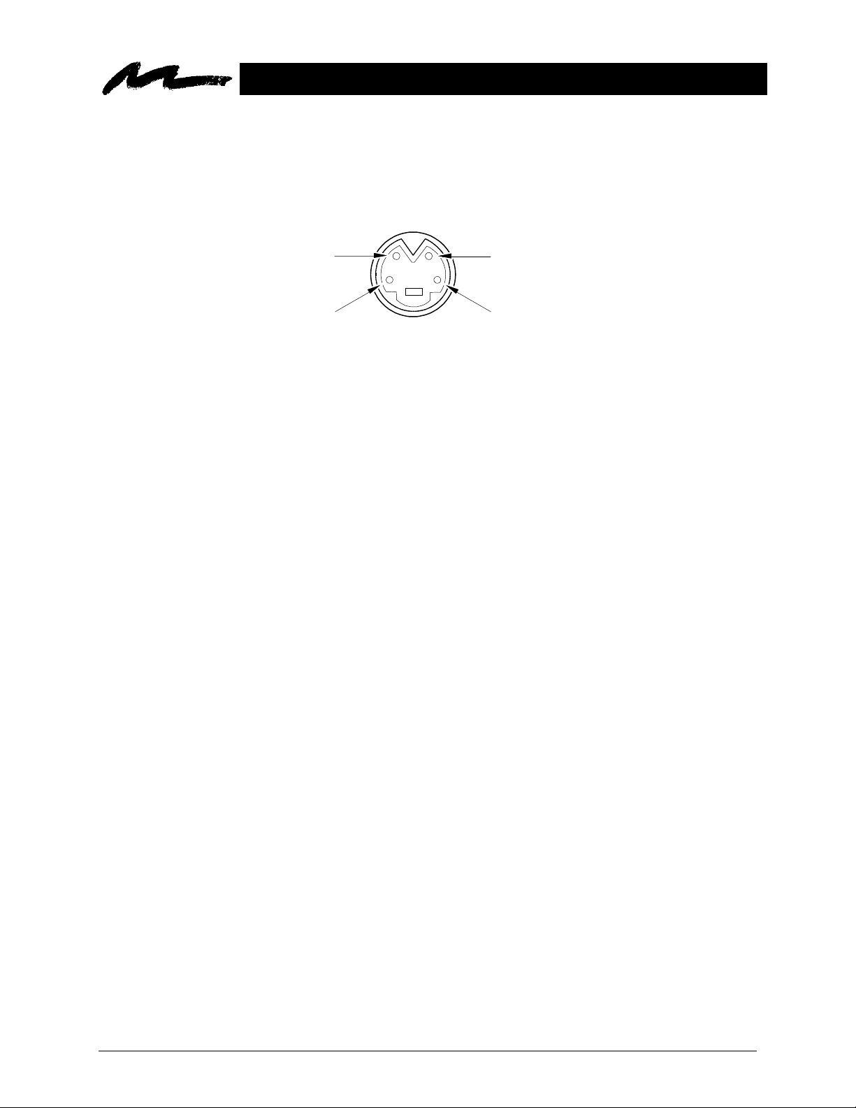
B-1. S–Video Input Signal Terminal
The following illustration (Figure B–1) identifies the terminal connections for the Mini DIN 4–pin.
Chrominance
Signal
Ground
Figure B-1. S–Video Input (Mini DIN 4–pin)
Video input is in the following order of priority:
S–video input terminal
•
RCA jack input terminal
•
Luminance
Signal
Ground
22 3M Multimedia Projector MP8610 3M 1998
Page 27

Appendix C: Detailed Setup Information
C-1. Setting Representation, Resolution
Most computers do not just support one single screen mode but rather a series of different modes which
differ in type of representation (text or full graphic), resolution (number of pixels) and number of colors.
Pre-stored standard mode settings for a variety of IBM compatible and Apple Macintosh computers help
the projector to recognize the current mode and adjust for optimum performance automatically.
Apart from this you can enter and save additional modes with any parameters by means of the menu
system. An upper limit is given by the maximum admissible pixel rate (Appendix A-1).
Adjust the projector to optimum display quality, as described below, by using the menu control (see
section 4-4). All steps described can be carried out via the keyboard or the remote control:
1. Adjust the background as necessary to obtain a display with the highest possible contrast. For use
under Microsoft Windows it is recommended that you close all applications first, and by using the
system control, adjust the desktop background to an even black-and-white raster.
2. Call up the main menu of the projector by pressing the
3. Select the
4. Open the
The current mode is displayed in the title block of the
desired. Confirm your selection by pressing the
5. Move to the menu item
6. Select the menu item
maximum intensity. Press the
Look at a finely structured area with grid lines. This area may have vertical interference lines
superimposed on it.
Setup
menu.
Setup
menu by pressing the
Pixel
Brightness
ENTER
and select the same image resolution as your computer.
and correct the setting so that white areas are projected with
ENTER
key for automatic adjustment.
key.
ENTER
MENU
Setup
key
key.
menu. Change the mode field if
7. Select the menu item
of adjustment is correct when the number of lines decreases. The setting is optimal when no more
interference lines can be seen. An automatic setting of tracking and synchronization can be called
up by operating the
displayed.
3M 1998 3M Multimedia ProjectorMP8610 23
Tracking
ENTER
(image width) and adjust for minimum interference. The direction
key. This works fine if an image with high contrast content is
Page 28
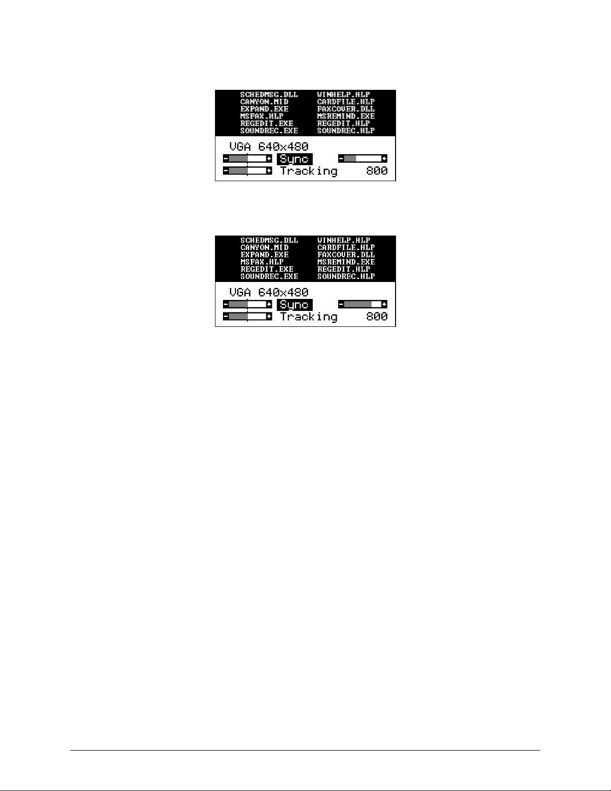
8. Synchronize the phase position of the pixel frequency and scanning frequency. Choose the menu
item
. Image interference’s and flickers can be observed with some settings as shown in the
Sync
following figure:
9. In a range of several settings an image is projected that is free of interference. If the sync-setting
is correct, the image will improve as shown in following figure:
10. An automatic setting of the synchronization can be called up by using the
ENTER
key.
11. Minor interference, where one color meets another, can be corrected by manually adjusting the
Brightness
and
Contrast
. Normally, the contrast should be set to approximately the medium
value. Lower values cause an increase in background intensity.
12. Center the projected image using the
13. To leave the Setup menu, press the
MENU
H. off
and
key.
V. off
settings.
14. If parameter settings have been changed, a warning is displayed. Confirm the changed settings
by using the
ENTER
key.
24 3M Multimedia Projector MP8610 3M 1998
Page 29
C-2. Factory Default Settings
The following table shows the possible settings of the projector. These settings can be restored by
pressing
ENTER
main power of the projector.
and the
button on the control panel (backside of projector) when switching on the
The projector will start immediately and a message
Parameter factory settings restored
in the starting
picture will indicate the default settings are reset. The default settings of the projector are underlined.
Menu Submenu Possible Settings
Setup*/Picture** <Mode>* Five user Modes: User mode 1, User mode 2, ..., User mode 5
VGA Text 720 x 400
VGA 640 x 350, VGA 640 x 400, VGA 640 x 480
Mac LC 640 x 480
Mac 640 x 480
VESA 640 x 480 72 Hz, VESA 640x480 75 Hz
VESA 640 x 400 85 Hz, VESA 640x350 85 Hz
VESA 800 x 600 56 Hz, VESA 800x600 60 Hz
VESA 800 x 600 72 Hz, VESA 800x600 75 Hz
VESA 800 x 600 85 Hz, VESA 1024 x 768 43 Hz
VESA 1024 x 768 60 Hz, VESA 1024 x 768 70 Hz
Quadra 832x624
Brightness bar
Contrast bar
V. off.* bar
H. off* bar
Color ** bar
Inverse* on, off
Sync* bar
Tracking* automatic adjustment, manual entry of pixel number/line
Pix.* 640x350, 640x400, 720x400, 640x480, 800x600, 832x624,
1024x768
Option Projection std., , ,
Lamp Mode std., eco.
Remote on, off
Auto Mode* on, off
Language English, Franç ais, Español, Italia na, Nederlands, Svenska, Deutsch
Help on, off
Lamp* bar
Sog* bar
Deinterlacing on, off
Reset Restore video modes to factory default settings
Std.** Auto/ PAL BGHI/ NTSC M/ SECAM/ NTSC 44/ PAL M/ PAL N/
PAL 60/ NTSC Comb
<Sync Mode>* Sep. TTL Sync, Sep. Ana. Sync, Comp. TTL Sync,
Comp. Ana. Sync, Sync on Green
Hue** bar
NTSC** full, centered
Audio Volume bar
Treble bar
Bass bar
Balance bar
Audio o n, off
Stereo on, off
<Audio assignment> Data/Video, S-VHS/Data, S-VHS/Video
<Video Mode> Data, Video, S-VHS
3M 1998 3M Multimedia ProjectorMP8610 25
Page 30
Ap pendix D : Replacem ent Parts/Accessories
D-1. Accessory Parts List
Part Description Part Number
Projection Lamp Kit
- Metal Halide Lamp (400W)
- Air Filter
Air Filter
Power Cords (U.S., UK, Europe)
For special power cords. See Appendix D-3
VGA Cable (15-15 pin M/M) DY-0205-1271-0
Video Cable (S–Video mini DIN–4pin) DY-0205-1010-2
Composite Video Cable (RCA to RCA) DY-0205-1008-6
Audio Cable (RCA to 3.5 mm stereo) DY-0205-1359-3
PC Serial Cable (PC mouse connection) DY-0205-1007-8
Remote Control 78-8118-3475-9
Mac Cable Set (optional) DY-0205-1361-9
Carry Case (optional) 78-6969-8579-1
Shipping Case (optional) 78-6969-8580-9
Monitor Splitter Box Kit (optional) 78-6969-8597-3
Mouse Y-Cable (optional) DY-0205-1507-7
(included in lamp kit
78-6969-8577-5
)
78-6969-8577-5
78-8118-3476-7
DY-0205-1356-9 (U.S.)
DY-0205-1355-1 (UK)
DY-0205-1354-4 (Europe)
Extension Cable Kit (optional) 78-6969-8582-5
Stereo mini-jack (optional) 26-1012-0683-2
Document Camera – 120 VAC 60 Hz (optional) 78-6969-8578-3
Document Camera – 220 VAC 50 Hz (optional) 78-6969-8724-3
Ceiling Mount Kit (optional) 78-6969-8581-7
Mac Cable Set (optional), Part number DY-0205-1361-9: This kit contains a Mac mouse adapter and a
Mac video cable.
Monitor Splitter Box Kit (optional), Part number 78-6969-8597-3
provides the user with the option to independently operate a PC monitor from the MP8610 projector.
(Maximum picture frequency: 80 MHz).
Extension Cable Kit (optional), Part number 78-6969-8582-5: The extension cable kit includes a video
amplifier and 20 m (65 ft.) video cable. The kit increases the allowable distance between the projector
and the video source without burdening the video source.
Mouse Y-Cable (optional), Part number DY-0205-1507-7: This cable provides user with the
option to simultaneously operate the MP8610 remote mouse and a PC mouse (only works with
Microsoft serial mouse).
: The Monitor Splitter Box Kit
26 3M Multimedia Projector MP8610 3M 1998
Page 31

D-2. How to Order
Please order these parts through your dealer, or contact 3M Customer Service at the following number:
In U.S. or Canada:
•
In other locations, contact your local 3M Sales office.
•
1–800–328–1371
3M 1998 3M Multimedia ProjectorMP8610 27
Page 32

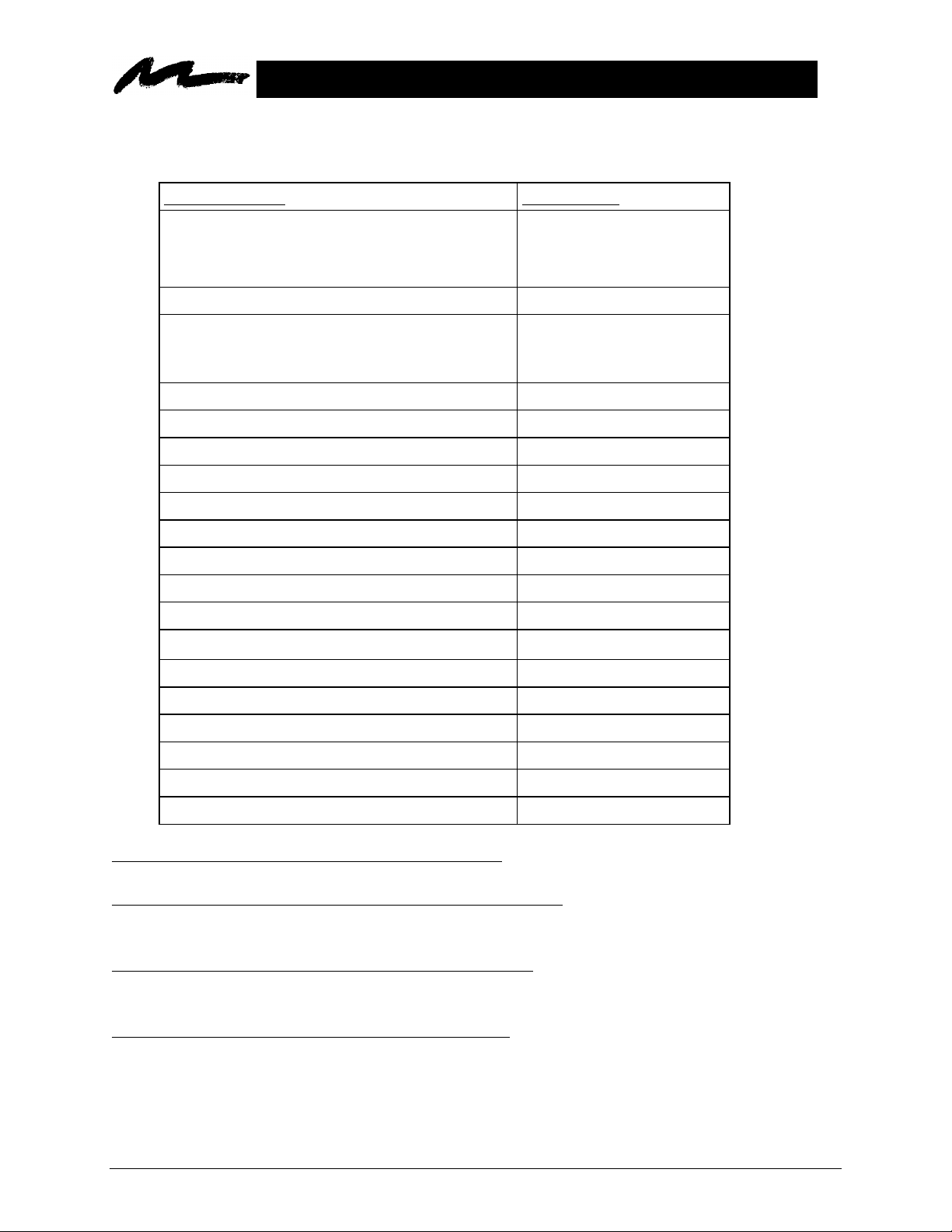
D-3. Power Cord Sets
A standard power cord set (U.S., UK, or European) will be included with each MP8610. If you need a
special power cord set contact your local 3M authorized dealer. The power cords must be in accordance
with the regional and corresponding national safety regulations and be properly approved. Examples of
these power cords are shown in Figure D-1.
North America
UL Listed CSA Certified
15A 125VAC
Germany, Netherlands,
Spain, France, Greece
VDE Certified
10A 250VAC
Great Britain
AUSTA Certified
13A 250VAC
Italy
IMQ or BASEC Certified
10A 250VAC
Switzerland
SEV Certified
10A 250VAC
Australian
SAA Certified
10A 250VAC
Denmark
Complies with Danish Standard
6/10A 250VAC
Figure D-1. Power Cord Sets
28 3M Multimedia Projector MP8610 3M 1998
Page 33

Glossary
Glossary of Terms
Amorphous Silicon
See Thin-Film Transistor.
Composite video
A video signal that combines all color and timing components of the picture in a single input line. The
U.S. standard is NTSC. European standards are PAL and SECAM.
Hz, KHz, MHz (Hertz, Kilohertz, Megahertz)
Hertz is a unit of measurement used to express the frequency, in cycles per second, of an electrical signal
or event. (Kilohertz = 1000, Megahertz = 1 million cycles per second).
Keystone correction
Keystoning (distorted image) is caused when the path of the projector light beam is not perpendicular to
the screen. Projectors normally project the image with an angle (e.g. 16°) on the screen. The optical
system can be designed for distortion free projection at this angle (keystone correction).
Lumens
A measure of light output on a screen or other surface. One lumen is the light of one candlepower on
each square foot of a surface of a sphere at a radius of one foot from the light source.
Metal halide lamp
A metal halide lamp is a modified mercury arc lamp that is extremely bright. It is filled with a gas with
elements known as “halogens”. The properties of this fill gas allows the lamp to burn longer and
brighter than ordinary incandescent lamps.
NTSC (National Television Systems Committee)
Standard for television signals and other video equipment signals. Uses interlaced scans and 525
horizontal lines per frame at a rate of 30 frames per second.
PAL (Phase Alternate Line)
The format for color television signals used in England, Germany, the Netherlands, and several other
countries. PAL is an interlaced format with 25 frames per second and 625 lines per screen.
Pixel
Short for “picture element.” Unique position on a display that consists of a single dot or group of three
dots (red, green & blue). Total pixels are usually expressed in horizontal x vertical dimensions (e.g. 640
x 480).
Power ON/OFF switch
The power ON/OFF switch is used to turn the machine on and off. The power switch is located on the
back of the projector in the lower left-hand corner.
3M 1998 3M Multimedia ProjectorMP8610 29
Page 34

Refresh rate
The number of times the screen image is “painted” or refreshed per second, expressed in Hz.
Remote control sensor
The remote control sensor is located on the front of the projector. It receives signals from the remote
control transmitter (direct line-of-site or bounced off of the projection screen) which control the different
operating functions of the projector. See remote control transmitter.
Remote control transmitter
Allows remote operation of the projector functions by aiming the transmitter directly at the sensor
(maximum range) on the front of the projector or aiming the transmitter at the projection screen so the
signal will bounce off the screen and back to the sensor. The remote also has mouse emulation
capability that will also control the mouse functions of the computer-input source.
Resolution
The number of pixels available in a display device for creating images. Expressed as a number of
columns by number of rows (e.g. VGA resolution, 640 x 480 or 720 x 400).
S-Video
A video signal that separates luminance (Y) and chrominance (C) signals. Also known as Y/C video.
SECAM (Séquentiel Couleur à Mémoire)
The color television standard developed in France and used in certain other countries.
SYNC
The timing of the computer's video signal. Usually a PC uses two separate lines for horizontal
synchronization (beginning of the line) and vertical synchronization (beginning of the frame). This
scheme is called
separate sync
If the two synchronization signals are transmitted on a single extra line, this is called
.
composite sync
. If
the composite sync signal is transmitted together with a video signal (usually the green video signal), this
is called
sync on green
. The projector can be set to handle all three kinds if synchronization schemes.
Thin-Film Transistor (TFT)
A tiny (less than fifty microns across) nearly transparent wafer of semi-conduction silicon. These act as
extremely precise electronic switching mechanisms.
VGA (Video Graphics Array)
This is a standard analog interface for PC computers. The resolution for text mode is 720 x 400 and for
graphics mode 640 x 480.
Video
The capability to project images from a VCR, Laser Disc, or PC with CD-ROM Drive is a standard
analog interface for PC computers. The resolution for text mode is 720 x 400 and for graphics mode 640
x 480.
30 3M Multimedia Projector MP8610 3M 1998
Page 35

Index
Index
A
Air Filter..................................................................15
Amorphous Silicon..................................................29
B
Batteries............................................................ 10, 19
C
Composite video ..................................................... 29
F
Factory Default Settings.......................................... 25
I
Important Safeguards
Intended Use
Inventory List............................................................ 3
K
Keystone ........................................................... 19, 29
L
Lumens....................................................................29
M
Machine Characteristics............................................ 4
Metal halide lamp................................1, 4, 12, 13, 29
Mouse adapter...........................................................3
Mouse emulation................................... 4, 5, 6, 17, 30
...........................................................1
........................................1, 7
N
NTSC.................................................. 4, 9, 11, 25, 29
P
PAL.....................................................................4, 29
Pixel............................................................ 17, 23, 29
Projector-to-Screen Distance .............................. 6, 20
R
Refresh rate............................................................. 30
Remote control transmitter.................................. 3, 30
Resolution......................................................... 23, 30
S
SECAM......................................................... 4, 29, 30
Standby Mode........................................................... 7
S-Video............................................................. 11, 30
SYNC...................................................................... 30
T
Troubleshooting...................................................... 17
V
VGA.......................................................... 3, 9, 25, 30
Video............................. 2, 6, 9, 11, 19, 22, 25, 26, 30
- - - - - - - - - - - - - - - - - - - - - - - - - - - - - - - - - - - - - - - - - - - - - - - - - - - - - - - - - - - - - - - - - - - - - - - -
The contents of this manual are subject to revision without prior notice.
3M assumes no responsibility for the infringement of special rights of a third party or other rights that may arise out of the use of
the information contained in this manual.
Reproduction of this manual in any form without prior permission is strictly prohibited.
3M 1998 3M Multimedia ProjectorMP8610 31
Page 36

(Intentionally Blank)
32 3M Multimedia Projector MP8610 3M 1998
Page 37

Let us help you make the most of your next presentation. We offer every thing from presentation supplies to tips for
g
g
g
,
,
,
p
,
p
better meetings. And we're the only transparency manufacturer that offers a recycling program for your used
transparencies. For late-breaking news, handy references and free product samples, visit our Internet Website.
s
Printed on 50% recycled wastepaper,
including 10% post-consumer wastepaper
3M 1998 D Y -0205-XXXX-X Rev. A
3M Austin Center
A145-5N-01
Buildin
6801 River Place Blvd.
Austin
TX 78726-9000
3M Canada
P.O. Box 5757
London
Ontario, Canada
N6A 4T1
3M Mexico
A
Mexico
Mexico
S.A. de C.V.
artado Postal 14-139
D.F. 07070
http://www .3m.com/me e tin
e-mail: m eetin
3M E uro
e
Boulevard de l'Oise
9500 Cerge Pontoife Cedex
France
s@mmm.com
3M 1998 3M Multimedia ProjectorMP8610 33
 Loading...