

Page 1

AERO
Congratulations on your purchase of an Aero!
Please read the following sections of this manual to get
started with your new autonomous aircraft.
1 Meet the Aero 7 Fly-by-wire mode
2 Safety 8 Command modes
3 Charge battery 9 Missions
4 Setup 10 Preflight steps
5 Manual mode 11 Takeo & landing
6 Stabilize mode 12 Postflight steps
Meet the Aero
left wing
nose
body
right wing
motor
tail boom
tail
1
Page 2
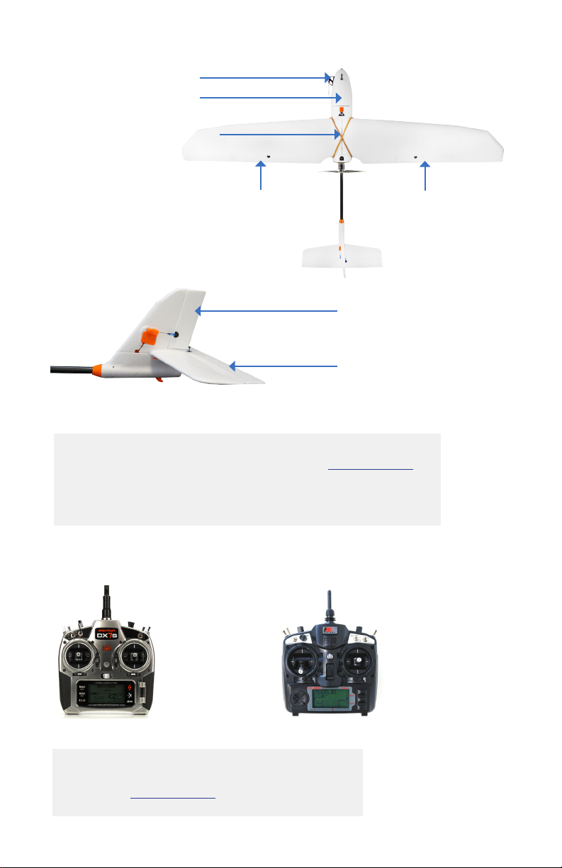
airspeed sensor
battery compartment
electronics compartment
(under wings)
left aileron
rudder
elevator
If the terms above are unfamiliar to you, visit 3dr.com/learn,
and dive into the exciting world of planes with our
Introduction to Flying Fixed-Wing Aircraft.
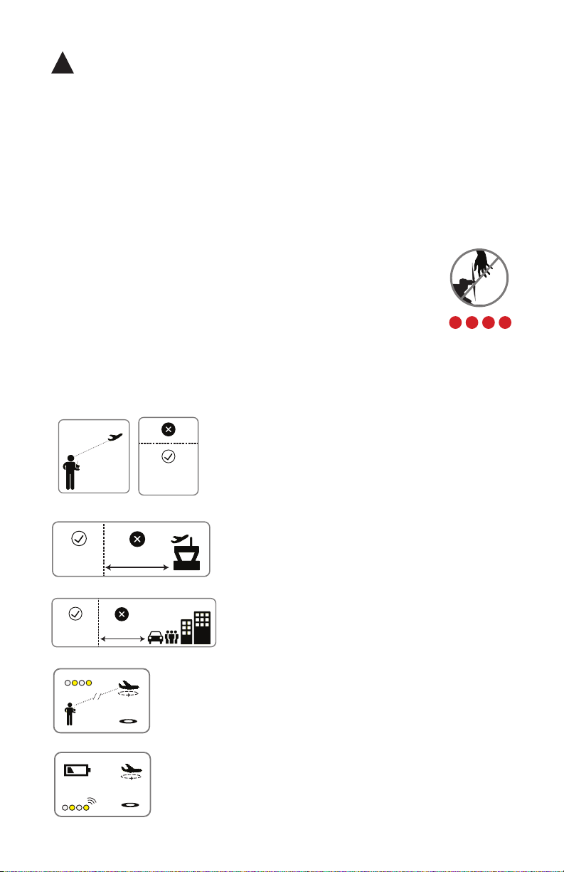
RC transmitter
right aileron
Spektrum FlySky
If you did not order an RC transmitter with your
Aero, visit 3dr.com/learn for instructions.
2
Page 3
!
visual line
of sight
400 ft
(120 m)
5 miles (8 km)
400 ft
(120 m)
Safety
Before you fly, always determine the boundaries of your safe flying area. If
the Aero moves outside the designated area or exhibits instability in flight,
switch to fly-by-wire mode and land the plane manually.
The Aero will not avoid obstacles on its own, including during missions. As
the operator, it’s your job to recognize and avoid obstructions while flying.
Always be ready to regain manual control of the plane in the event of an
unsafe situation.
Spinning propellers can cause serious injury. The safety button
indicates the status of the motor to help you prevent hazardous
contact with the Aero’s high-speed propeller. When the Aero is
powered on, the safety button will blink red; the motor is inactive
and the propeller is safe to handle. When you’re ready to fly, press
and hold the safety button until it shows solid red. This indicates
that the motor is active and the propeller can spin if armed. To
make the propeller safe to handle again, press and hold the safety
button until it blinks red.
Always fly below 400 ft (120 m) and within your
visual line of sight. Don’t let the Aero get too far
visual line
of sight
400 ft
(120 m)
away from you; make sure you can always see its
orientation. Don’t fly in low light, heavy wind, rain,
or other conditions that might impede visibility.
5 miles (8 km)
100 ft (30 m)
Always fly at least five miles (8 km) away from
airports and other areas where pilots operate
manned aircraft.
Always fly at least 100 feet (30 m) away from
people, vehicles, and buildings. Make the safety
of people and property your first priority!
If the Aero looses contact with the RC transmitter, it will
return to the launch point automatically and enter into a
circle pattern above the launch point, indicated by a
blinking yellow status LED.
If the battery reaches 33% of its remaining charge, the
Aero will return automatically to circle above the launch
point, indicated by a blinking yellow status LED and a
quick repeating tone.
3
Page 4

Charge battery
The Aero is powered by a rechargeable lithium polymer
(LiPo) battery. Store the battery at half charge, then charge
fully before flying. Batteries must ship at half charge, so
please charge before your first flight. Each full battery
provides approximately 40 minutes of flight time.
battery charger
Connect the charger to the power adapter cable and a
wall outlet. Connect the red cable to the + port and the
black cable to the - port.
Set the charger to LiPo and 3A.
LiPo 3A
4
+
–
Page 5
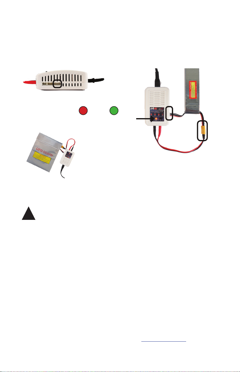
Connect the white connector to the 4S port. Join the two yellow
connectors together. Secure the battery inside the guard bag while
charging, and charge until the status indicator displays green.
4S
Charging Complete
guard bag
!
Battery safety
Protect the battery from extreme heat, extreme cold, puncturing,
and flammable surfaces. Always transport, charge, and store
the battery in the guard bag.
Charge the battery using a designated LiPo balance charger only.
Always monitor the battery while charging.
Flying with a low battery is a safety risk and can render the battery
permanently unusable. Always fly with a fully charged battery.
Inspect the battery for damage before takeo and after landing.
If you observe any swelling of the package or the battery ceases
to function, locate your local battery recycling center to dispose
of the battery. In the US and Canada, visit call2recycle.org to
find a location. Do not dispose of the battery in the trash.
5
Page 6
Setup
Follow these instructions to take the Aero from
travel configuration to flight configuration.
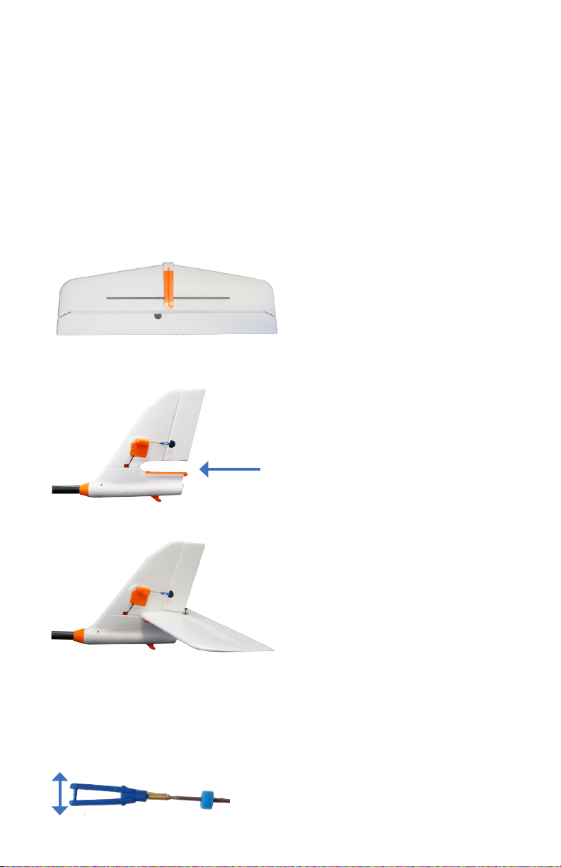
Slide the horizontal stabilizer into the vertical stabilizer
1
along the orange groove. Make sure not to stress any
of the components on the tail.
horizontal stabilizer
vertical stabilizer
complete tail assembly
On the top of the horizontal stabilizer, open the
blue clasp at the end of the servo rod.
6
Page 7
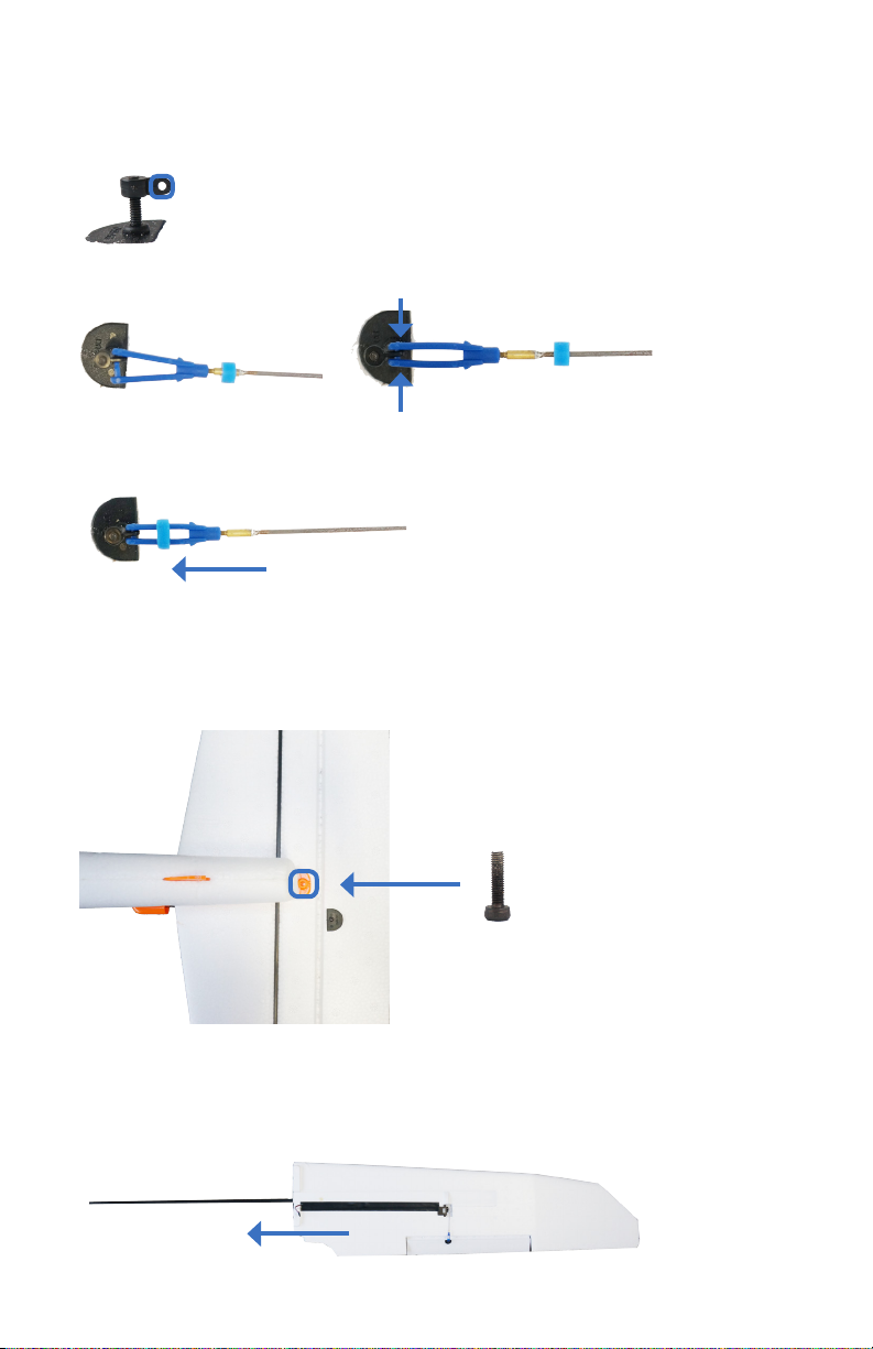
Insert the pegs on the clasp into the open space in
the servo horn, and close the clasp.
servo horn
Slide the blue rubber ring over the clasp to secure it in place.
Turn the plane over and insert the provided tail screw
into the horizontal and vertical stabilizers.
tail screw
Locate the wing spar (long rod) and the two wings.
2
Slide a wing onto the spar.
7
Page 8

Slide the other wing onto the spar.
Do not twist the wing or the spar so as not to stress the foam.
complete wing assembly
Locate the two cables inside the electronics compartment marked
AILE. Connect these cables to the two cables on the wings marked
AILE. (Either of the wing cables can connect to either of the plane
cables; the order doesn’t matter.)
plane AILE cables wing AILE cables
Place the wings over the body of the Aero with the foam squares
fitted into the matching space in the electronics compartment.
Make sure not to pinch the AILE cables.
wings placed onto the body of the Aero
8
Page 9
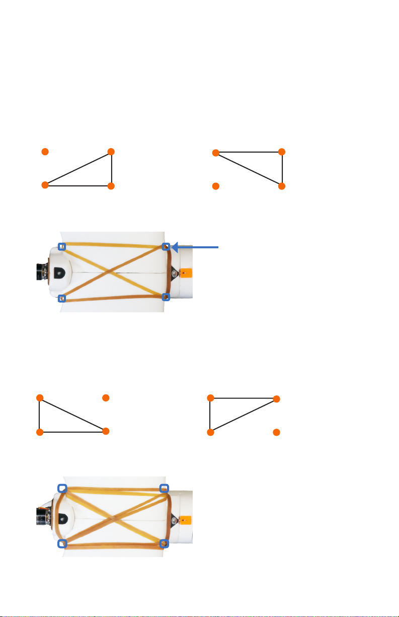
Locate the four large rubber bands. Use the bands to secure
the wings to the body of the Aero by the four orange knobs
on the body around the wings.
Attach two of the bands to the two knobs on one of the short
sides and opposite knobs on the opposing side.
add first band add second band
orange knobs
Repeat on the other short side with the remaining two rubber
bands, resulting in two pairs of opposing right triangles.
add third band add fourth band
complete band assembly
9
Page 10
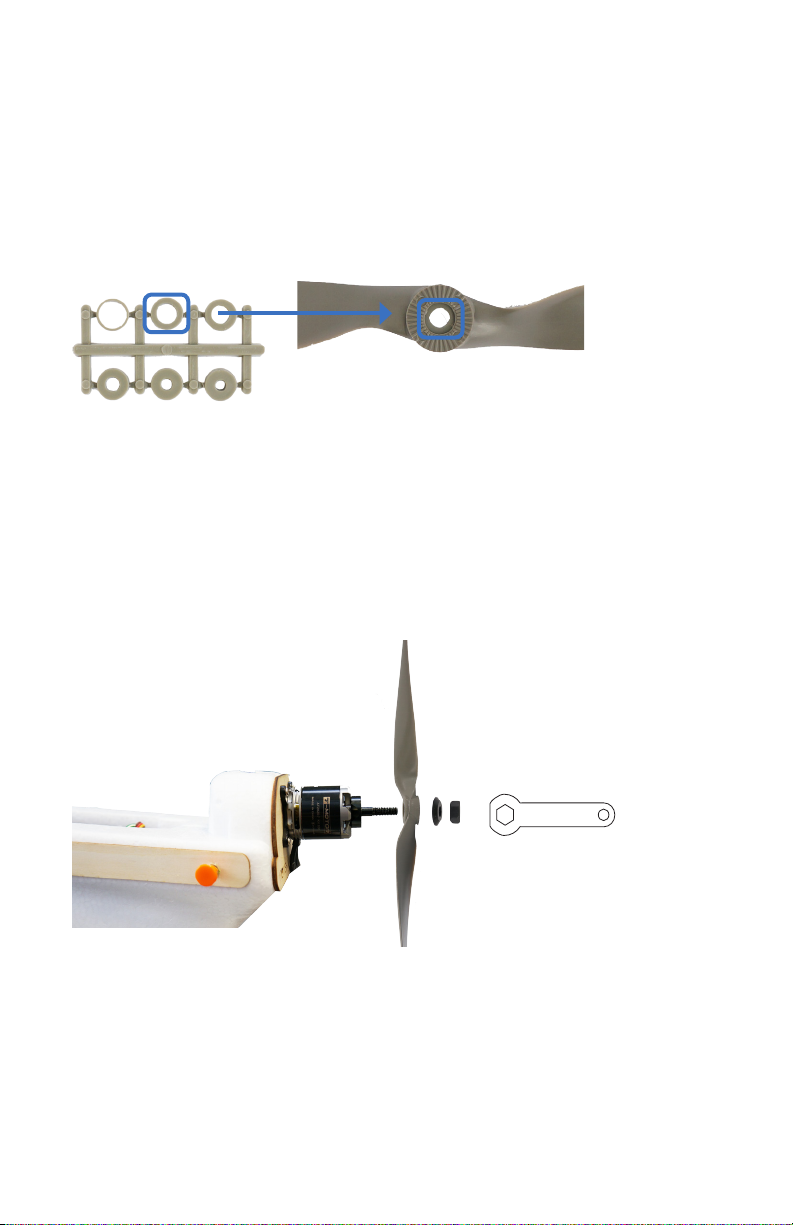
Locate the rings inside the propeller package. Remove
3
the ring with the second-largest internal diameter, and
insert it into the back of the propeller hub.
Remove the nut and the washer from the motor, add the
propeller with the writing on the propeller facing towards
the nose of the plane, add the washer and the nut over the
propeller, and tighten the nut.
10
Page 11

The tail boom arrives attached to the Aero. Follow these
instructions to remove the tail boom for travel.
Disconnect the RUDD and ELEV cables inside the
electronics compartment.
Remove the screws on the body and the tail indicated below.
body
tail
Pull out the tail boom to remove. To reattach, reverse these steps.
11
Page 12

Setting flight modes
On 3DR transmitters, use the two-position switch and the
three-position switch shown below to select a flight mode.
Spektrum mode switches
two-position switch
marked GEAR/MIX
three-position switch
marked FLAP/GYRO
available positions 0, 1, 2
FlySky mode switches
three-position switch
marked F MODE
available positions N, 1, 2
two-position switch
marked AIL D/R
available positions 0, 1
The two-position switch activates one of the two groups of modes
then the three-position switch selects the specific mode within the
group. The three-position switch can be set forward (away from you),
center, and back (towards you). The two-position switch can be set
forward and back.
three-position mode switch
forward
(away from you)
12
center
back
(towards you)
two-position mode switch
forward
(away from you)
back
(towards you)
Page 13

The Aero includes six flight modes. Manual mode, two assisted flight
modes (stabilize and fly by wire), autonomous mission mode, and two
command modes (loiter and return to launch). The following sections
of this manual describe the behavior of each mode. The Aero’s six
modes are assigned to your transmitter’s mode switches according to
model.
Flight modes on Spektrum
With GEAR/MIX set to MIX,
set FLAP/GYRO to: 0 for AUTONOMOUS
1 for FLY BY WIRE
2 for RETURN TO LAUNCH
With GEAR/MIX set to GEAR,
set FLAP/GYRO to: 0 for MANUAL
1 for STABILIZE
2 for LOITER
Flight modes on FlySky
With AIL D/R set to 0,
set F MODE to: N for RETURN TO LAUNCH
1 for FLY BY WIRE
2 for AUTONOMOUS
With AIL D/R set to 1,
set F MODE to: N for LOITER
1 for STABILIZE
2 for MANUAL
13
Page 14

Manual mode
Left Stick
Left Stick
Fly with fine-tuned manual control without autopilot assistance.
Manual mode gives you the most direct input to the control
surfaces, resulting in precise in-flight adjustment. Try manual
mode if you’re an experienced RC plane operator.
GPS
no GPS lock required
X
Manual mode RC controls
throttle
yaw
Throttle up
Throttle down
Throttle fully down
pitch
roll
Increase motor
speed.
Decrease motor
speed.
Stop motor.
14
Page 15

Left Stick
Yaw left
Left Stick
Left Stick
Left Stick
Left Stick
Left Stick
Yaw right
Pitch up
Pitch down
Turn left.
Turn right.
Pitch up.
Roll left
Roll right
Pitch down.
Roll left.
Roll right.
15
Page 16

Stabilize mode
Left Stick
Left Stick
Stabilize mode provides manual control with an added autopilot
safeguard: Release the right stick and the Aero will automatically
return to a level flying orientation. Use stabilize mode for the
freedom of manual control with return-to-level stabilization.
GPS
no GPS lock required
X
Stabilize mode RC controls
throttle
yaw
Throttle up
Throttle down
Throttle fully down
pitch
roll
Increase motor
speed.
Decrease motor
speed.
Stop motor.
16
Page 17

Left Stick
Left Stick
Yaw left
Left Stick
Left Stick
Left Stick
Left Stick
Left Stick
Yaw right
Pitch up
Pitch down
Turn left.
Turn right.
Pitch up.
Pitch down.
Roll left
Roll right
Roll and pitch center
Roll left.
Roll right.
Automatically level.
17
Page 18

Fly-by-wire mode
Left Stick
Left Stick
Let the autopilot manage the control surfaces, and navigate based
on where you want the Aero to fly. Fly-by-wire mode* (FBW) is the
easiest way to fly and is the recommended mode for new fliers.
*APM:Plane mode FBWA
GPS
no GPS lock required
X
FBW mode RC controls
throttle
yaw
Throttle up
Throttle down
Throttle fully down
stabilized pitch
stabilized roll
Increase motor
speed.
Decrease motor
speed.
Stop motor.
18
Page 19

Left Stick
Left Stick
Yaw left
Left Stick
Left Stick
Left Stick
Left Stick
Left Stick
Yaw right
Pitch up
Pitch down
Turn left.
Turn right.
Pitch up.
Pitch down.
Roll left
Roll right
Roll and pitch center
Fly to the left.
Fly to the right.
Automatically level.
19
Page 20

Command modes
Use command modes to enter into an automatic flight pattern.
Once set to a command mode, the Aero will continue to follow
the specified pattern until otherwise directed. Command modes
require GPS lock prior to takeoff.
Loiter mode: GPS-positioned circling
» The Aero will enter into a circle pattern with a radius of
60 meters at the current altitude.
» Move the right stick to adjust the position of the circle.
GPS
GPS lock required
Return-to-launch mode: circling over launch point
» The Aero will return to the position where it acquired GPS lock
and enter into a circle pattern at an altitude of 100 meters.
GPS
GPS lock required
20
Page 21

Missions
Use a ground station computer with the provided Telemetry
Radio to fly a fully autonomous mission. To download software
and learn how to plan a mission, visit 3dr.com/learn.
laptop ground station with 3DR Telemetry Radio
Once you have saved a mission to the Aero, ensure that the
autopilot acquires GPS lock during the preflight steps, and
take off in manual, stabilize, or fly-by-wire mode. Fly to the
approximate altitude of the first waypoint, and switch into
autonomous mode to start the mission.
To fly a mission with automatic takeoff and landing, visit
3dr.com/learn for instructions.
GPS
GPS lock required
Do not set the Aero to autonomous mode without following
!
the mission planning instructions at 3dr.com/learn.
21
Page 22

Preflight steps
Select an open area for flying, away from people and buildings,
and remember to bring the flight checklist and a fully charged
battery. Follow these steps every time you fly.
Flight Checklist
Preflight
Go outside to an open area,
Connect
1
2
and inspect aircraft.
charged battery.
» Wings and tail attached
» Hold aircraft still
» Tail boom secure
while powering on.
» Servos and rods secure
» Secure lid.
» Airspeed sensor secure
» Check for balanced
» Propeller tight
center of gravity.
» Transmitter on
Check manual
Check autopilot
3
4
controls.
stabilization.
» Pitch up and down
» Throttle
» Roll left and right
» Pitch up and down
» Roll left and right
» Yaw left and right
Press and hold
Check LED for blinking
6
5
safety button until
blue (no GPS) or blinking
solid red.
green (GPS locked).
GPS
X
GPS
LED
Initializing, please wait
Autopilot ready, no GPS
Autopilot ready, GPS locked
Armed, ready to fly
Loss of RC signal, automatic return to launch
System error, see troubleshooting guide
Safety Button
Inactive, safe to handle
Active, press and hold button before handling
Before flying, examine the Aero to ensure that all
1
components are secured in flight configuration.
» Check that the wings, tail, and tail boom are fully
flight checklist
assembled and securely attached.
» Check that the propeller is secured tightly to the
motor.
» Check that the servo rods are secured to the servo
horns with the blue clasps.
tail servos wing servos
22
Page 23

Check that the airspeed sensor is secured to the side of
the Aero and the tube is free from obstructions.
airspeed sensor
If any of the components or assemblies in these checks are
not secure, tighten the screws or use CA glue (super glue)
to secure the components to the foam.
Power on the RC transmitter, and set the throttle fully down.
Open the battery compartment by sliding the knob
2
on the orange switch and lifting out the foam lid.
23
Page 24

Secure a charged battery to the velcro strip within the
marked lines, and attach the yellow connectors.
Hold the Aero still and level while it powers on.
!
Secure with the velcro strap. Close lid by aligning
the orange notches at the nose.
With the battery connected and the lid secured, check that the
3
Aero is correctly balanced for flight. Hold the Aero with one finger
on each of the clear, plastic balancing points shown below. These
points indicate the Aero’s center of gravity.
24
Page 25

If the plane balances on your fingers, then the center of
gravity is correct. If it won’t balance, adjust the position of
the battery until you can balance the plane on two fingers as
shown below.
Check the LED for the status of the autopilot. If you plan to
4
use loiter, return-to-launch, autonomous, or any other GPSrequired modes during your flight, wait to see the blinking
green light, indicating GPS lock, before proceeding. If you plan
to fly only in manual, stabilize, or fly-by-wire modes, you may
proceed when you see the blinking blue light.
Initializing, please wait
LED
To arm the motor, press and hold the safety
5
button until it displays solid red.
safety button
Autopilot ready, no GPS
Autopilot ready, GPS locked
Inactive, motor disarmed
Active, motor armed
25
Page 26

Place the plane on the ground, and set the mode switches
Left Stick
Left Stick
Left Stick
6
to select manual mode. Move each of the sticks as shown,
and check for the corresponding movement of the motor
or control surfaces.
Raise the throttle slightly until the motor spins, then
immediately set the throttle back to fully down position.
Do not raise the throttle more than just enough to
!
spin the motor while the plane is on the ground, and
do not place your hands in the way of the propeller
while the motor is armed.
Motor spins.
26
Pitch down
Elevator tilts down.
Pitch up
Elevator tilts up.
Page 27

Left Stick
Left Stick
Roll left
Left Stick
Left Stick
Roll right
Yaw left
Left aileron tilts up,
right aileron tilts
down.
Left aileron tilts
down, right aileron
tilts up.
Rudder tilts left.
Yaw right
Rudder tilts right.
27
Page 28

Set the mode switches to stabilize, and hold the plane in front
7
of you. Move the plane as shown, and check for the stabilization
response from the control surfaces.
Test: Tilt the plane left.
Result: Left aileron tilts
down, right aileron tilts up.
Test: Tilt the plane right.
Result: Left aileron tilts up,
right aileron tilts down.
Test: Tilt the plane down.
Result: Elevator tilts up.
Test: Tilt the plane up.
Result: Elevator tilts down.
28
Page 29

Takeo & landing
Left Stick
Now you’re ready for takeoff! If you’re new to planes, we recommend
having a friend help you launch the Aero. Have your friend throw the
Aero while you control the transmitter.
We recommend setting the Aero to fly-by-wire mode for takeoff.
Find a launching area with at least 100 feet of clear space in front of
you. Face into the wind, and hold the Aero at the center of gravity.
Raise the throttle to center position to start the motor. Be careful not
to place your hand in the way of the propeller!
throttle center
Hold the Aero above your head, run, and throw the
plane at an upwards angle.
Once launched, the Aero will require immediate adjustment with
the transmitter to navigate away from the ground and up to the
desired altitude. Pitch up (right stick down) and add any other
necessary controls based on wind, speed, and terrain.
29
Page 30

Left Stick
Left Stick
When you’re ready to end your flight, follow these steps to land:
» Fly a circle pattern above your landing area.
» Come in on a final approach, flying into the wind at
an altitude of 20 to 40 meters.
» When the plane reaches an altitude of 10 meters, set the
throttle fully down to turn off the motor and glide down
on a 15 to 20 degree down-pitch angle.
» When the plane is one meter above the ground, pitch up
(flare) to land the Aero on the body of the plane instead
of the nose.
wind direction
pitch slightly down
throttle fully down
30
20-40 m
10 m
After stopping the motor at an altitude of 10 m, keep your
!
thumb on the throttle stick in fully down position to ensure
that the motor does not accidently spin during landing.
pitch up
1 m
Page 31

Postflight steps
To disarm the motor, press and hold the
1
safety button until it displays blinking red.
Disconnect battery
2
Turn off transmitter.
3
safety button
Inactive, motor disarmed
Active, motor armed
Your flight is now complete. Always following the preflight
and postflight steps described in this manual when you fly.
31
Page 32

FPV/OSD video
If you received an FPV/OSD video system with your Aero, visit
3dr.com/learn for instructions on operating your video system.
Learning more
Visit 3dr.com/learn for more instructions on flying, configuring,
and using a ground station with the Aero.
To learn more about the APM:Plane platform, including
adding new flight modes and flying autonomous missions,
visit plane.ardupilot.com.
Support
For customer support, contact us at help@3dr.com
or call our support line at +1 (858) 225-1414
Monday through Friday, from 8 am to 5 pm, PST.
Happy flying!
Aero User Manual A | ©3D Robotics, Inc. | 12 August 2014
32
 Loading...