

Page 1
AUTOPILOT
QUICK START GUIDE
Page 2
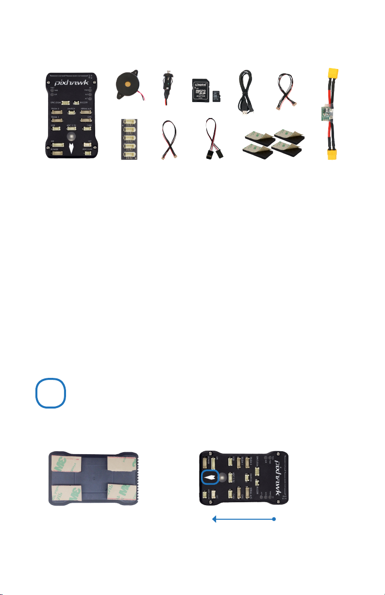
PARTS
1 2 3 4 5 7
8
1 Pixhawk
2 Buzzer
3 Safety switch
4 Micro-SD card and adapter
5 Micro-USB cable
6 Six-wire cable x2
9
GETTING STARTED
With the help of APM firmware, Pixhawk turns any
RC plane, copter, or rover into a full-featured personal
drone. Once you have a fully-assembled frame, follow
this guide to install Pixhawk.
10
7 Power module
8 I2C splitter module
9 Four-position I2C splitter cable
10 Three-wire servo cable
11 Mounting foam
11
1 Mount
2 Connect
3 Load firmware
4 Calibrate
6
1
MOUNT
Use the provided foam to mount Pixhawk as close as possible to your vehicle’s center of gravity.
Make sure to orient the board with the arrow pointing forward.
Attach the foam squares to the
corners of the board.
Vehicle front
Page 3

CONNECT
2
(Optional) Connect a 3DR
Radio to Pixhawk’s Telem
port using the 6-wire cable
provided with your 3DR Radio
Kit to receive data and
communicate with
the autopilot in flight.
(Required) Connect the 3DR
Power Module to the Power port
using the 6-wire cable to direct
power from your lithium polymer
(LiPo) battery to the autopilot.
(Required) Connect the buzzer
and safety switch.
(GPS or GPS+Compass required)
Connect a 3DR GPS+Compass to
provide the autopilot with positioning
data during flight. This kit includes a
6-wire cable to connect the GPS ports.
Connect the MAG to the I2C port using
the 4-wire cable provided with the 3DR
GPS+Compass.
(Optional) The I2C splitter expands the I2C port to allow up
to four additional peripherals to connect to Pixhawk. Use the
4-wire cable to connect the I2C splitter and add a compass
module, external LED, digital airspeed sensor, or other
peripherals to your vehicle.
Page 4
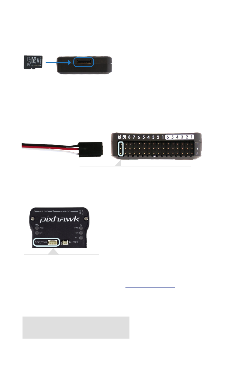
LOAD SD CARD INTO PIXHAWK
If the SD card is not preloaded into Pixhawk, insert the micro-SD card into the slot at the
bottom end of the board.
CONNECT RADIO CONTROL
FOR PPM RC RECEIVERS AND FUTABA S.BUS RECEIVERS
Connect the ground (-), power (+), and signal (S) wires to the RC
pins using the provided 3-wire servo cable.
FOR SPEKTRUM SATELLITE RECEIVERS
For a Spektrum DSM, DSM2, or DSM-X Satellite RC receiver, connect to
the SPKT/DSM port.
For a complete list of RC systems compatible with Pixhawk, visit the APM wiki page here.
FOR PWM RECEIVERS
Purchase a PPM Encoder module to connect a PWM
RC receiver to Pixhawk at store.3dr.com.
Page 5
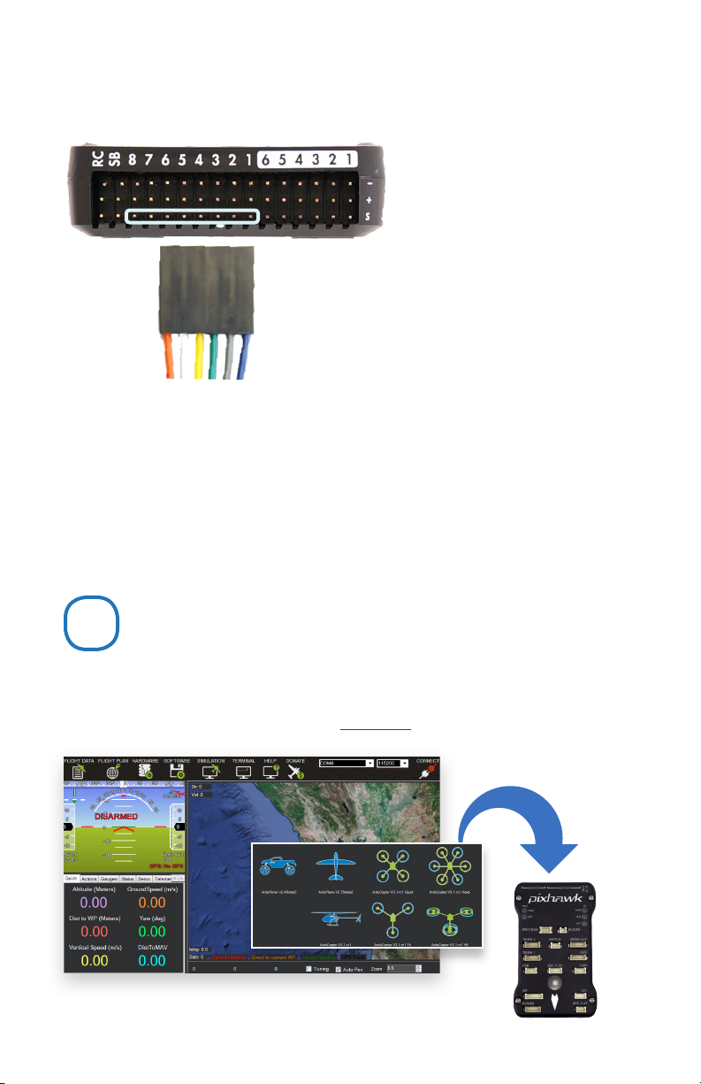
CONNECT OUTPUTS
FOR COPTERS
Connect each signal wire from the PDB to
the main output signal (S) pins by motor
number. Connect one wire for each motor
to the corresponding pin.
Pin 1 = Motor 1 Pin 5 = Motor 5
Pin 2 = Motor 2 Pin 6 = Motor 6
Pin 3 = Motor 3 Pin 7 = Motor 7
Pin 4 = Motor 4 Pin 8 = Motor 8
FOR PLANES
For planes, connect the control channel
wires to the main output signal pins.
Pin 1 = Aileron
Pin 2 = Elevator
Pin 3 = Throttle
Pin 4 = Rudder
FOR ROVERS
For rovers, connect the throttle and steering
wires to the main output signal pins.
Pin 3 = Throttle
Pin 4 = Steering
LOAD FIRMWARE
3
APM firmware is the brains of your autopilot operation and must be installed before using Pixhawk.
To load firmware onto Pixhawk, install a mission planner application on your ground station computer. Choose
either Mission Planner (Windows) or APM Planner for (Windows, OS X, and Linux).
Both applications are available for free download from ardupilot.com.
firmware
Mission planner
Page 6

Download Mission Planner (Windows)
Ardupilot.com Downloads Mission Planner
Mission Planner « Downloads
Sort by: Title | Hits | Date
■ MissionPlanner - Installer
Download APM Planner (Windows, OS X, and Linux)
Ardupilot.com Downloads APM Planner 2.0
Select the installer
package to download.
APM Planner 2.0 « Downloads
Sort by: Title | Hits | Date
■ APM Planner 2.0 Mac
■ APM Planner 2.0 Windows
■ APM Planner 2.0 Linux
INSTALL PLANNER
After selecting the correct file, read the safety information and select Download.
Open the file to run the setup wizard. Proceed through any security warnings, and install all
suggested drivers. When the installation is complete, open the application, and connect Pixhawk to your
computer using the micro-USB cable.
Select your platform to
download.
Your computer will automatically install the correct drivers. Do not select Connect at this time; Pixhawk can only
load firmware while unconnected to Mavlink.
Page 7

Select Initial Setup, Install Firmware, and select your vehicle.
When prompted, follow the directions to load the firmware. Once the status bar shows that the download is
complete, power cycle the board by disconnecting and reconnecting the USB.
If you hear a musical tone, your firmware installation is complete. If you hear a series of tones followed by three
beeps, disconnect the USB and reconnect while holding down the safety button. Upon restart, listen for a series
of tones followed by two beeps indicating that your firmware has loaded successfully.
Everything is OK:
musical tone
Pixhawk needs your attention:
beep BEEP beep... BEEP BEEP BEEP
beep BEEP beep...
BEEP BEEP
CALIBRATE
4
With Pixhawk connected to your computer, select the communication option from the drop-down menu for
PX4 FMU, set the rate to 115200, and select the Connect icon. Select Initial Setup and Mandatory Hardware to
access the calibration wizards.
Remove propellers before performing calibration.
!
Page 8
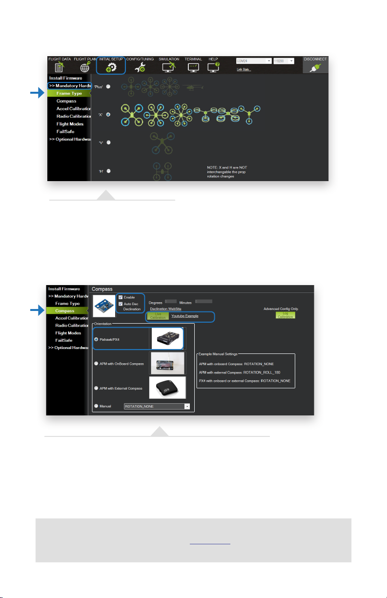
SELECT FRAME TYPE (COPTERS ONLY)
For copter, select your frame orientation.
CALIBRATE COMPASS
Select the options to enable the compass; to allow automatic declination
calculation; and to specify Pixhawk. Select Live Calibration to launch the wizard,
and follow the prompts.
Show Me
videos demonstrating live calibration techniques at 3dr.com/learn.
Page 9

CALIBRATE ACCELEROMETER
Select Accel Calibration, check the box for AC 3.0+, select Calibrate, and
follow the prompts to calibrate Pixhawk’s accelerometer. Make sure to wait a
couple of seconds before and after changing the positions of the vehicle.
RC CALIBRATION
5
4
6
left stick
right stick
Select Radio Calibration to teach Pixhawk to work with your RC
transmitter. Turn on your transmitter, select Calibrate Radio, and move
all sticks and switches to their extreme positions. Select Click when Done
once the red bars are set for all available channels.
SELECT FLIGHT MODES
Move each switch on your transmitter to its available positions. The mission
planner will indicate the currently selected position with green highlighting. Select
a mode for each switch position, and select Save Modes to assign.
Page 10
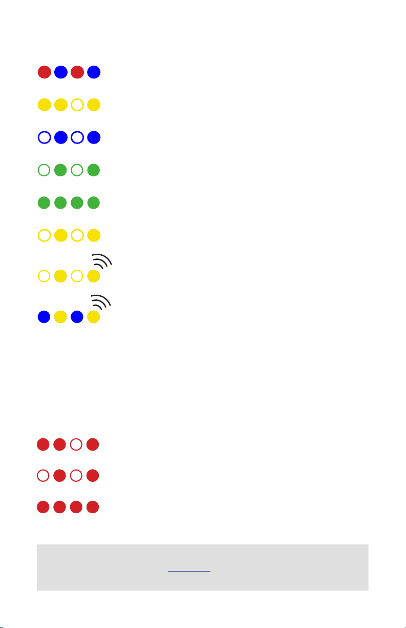
LED MEANINGS
Flashing red and blue: initializing. Please wait.
Double flashing yellow: error. System refuses to arm.
Flashing blue: disarmed, searching for GPS. Autonomous, loiter, and return-to-launch
modes require GPS lock.
Flashing green: disarmed, GPS lock acquired. Ready to arm. Quick double tone when
disarming from the armed state.
Solid green plus single long tone: armed and ready to fly!
Flashing yellow: RC failsafe activated.
Flashing yellow plus quick repeating tone: battery failsafe activated.
Flashing yellow and blue plus high-high-high-low tone: GPS glitch or GPS failsafe
activated.
SAFETY SWITCH MEANINGS
Quick, constant blinking: performing system check. Please wait.
Intermittent blinking: system ready. Press the safety button to activate.
Solid: ready to arm. Proceed to the arming procedure.
Learn more
about LED meanings and buzzer tones at 3dr.com/learn.
Page 11

PORTS
1
2
3
4
5
6
1 Spektrum DSM receiver
2 Telemetry (radio telemetry)
3 Telemetry (on-screen display)
7
8
9
10
11
12
13
14
15
4 USB
5 SPI (serial peripheral interface) bus
6 Power module
7 Safety switch button
8 Buzzer
9 Serial
10 GPS module
11 CAN (controller area network) bus
12 I2C splitter or compass module
13 Analog to digital converter 6.6 V
14 Analog to digital converter 3.3 V
15 LED indicator
3
1 Input/output reset button
2 SD card
3 Flight management reset button
4 Micro-USB port
1 2
ground
power
signal
1 Radio control receiver input
2 S.Bus output
3 Main outputs
4 Auxiliary outputs
1
2
4
3 4
Page 12

IMPORTANT NOTE
Please note that these instructions describe basic setup for Pixhawk and do not represent the
complete set of configuration procedures required to build a copter, plane, or rover.
For more information on ESC calibration, battery monitoring, failsafes, mode descriptions,
and more, visit ardupilot.com. Do not operate your vehicle without a complete understanding
of the online instructions.
SPECIFICATIONS
Processor
32-bit ARM Cortex M4 core with FPU
168 Mhz/256 KB RAM/2 MB Flash
32-bit failsafe co-processor
Sensors
ST Micro 16-bit gyroscope
ST Micro 14-bit accelerometer/magnetometer
MEAS barometer
MPU6000 accelerometer/magnetometer
Power
Ideal diode controller with automatic failover
Servo rail high-power (7 V) and high-current ready
All peripheral outputs over-current protected, all
inputs ESC protected
Interfaces
5x UART serial ports, 1 high-power capable, 2x with
HW flow control
Spektrum DSM/DSM2/DSM-X Satellite input
Futaba S.BUS input and output
PPM sum signal
RSSI (PWM or voltage) input
I2C, SPI, 2x CAN, USB
3.3 and 6.6 ADC inputs
Dimensions
Weight 38 g (1.3 oz)
Width 50 mm (2.0”)
Height 15.5 mm (.6”)
Length 81.5 mm (3.2”)
SUPPORT
For more information about Pixhawk and other documentation, visit
3dr.com/learn. For more instruction on using APM firmware and
planner software, visit ardupilot.com.
For customer support, contact us at help@3dr.com or call our
support line at +1 (858) 225-1414 Monday through Friday, 8 am to 5 pm, PST.
Page 13

SAFETY
Operating a powered vehicle of any kind can be a lot of fun, but it carries certain inherent risks. Regulations
governing the use of powered vehicles, including aircraft, vary from locale to locale, even within the same country
or district. It is your responsibility to ensure that you understand and comply with all local laws and regulations.
Safety basics:
• Never operate the vehicle or software in a way that could be dangerous to you, other people, or property.
• Always keep propeller arcs free of objects and body parts while the vehicle is live.
• Keep in mind that software and hardware failures happen. Although we design our products to minimize
such issues, you should always operate with the understanding that a failure could occur at any time and
without warning. Accordingly, you should take the appropriate precautions to minimize danger in case of
product failure.
• Never use the software or hardware for manned vehicles.
• Always operate within local laws and regulations.
• Do not operate the aircraft if you are under the age of 18.
Additional safety information:
• Be sure to maintain safe distances between people and your aircraft.
• Never operate your aircraft if your ability to do so with the utmost attention to safety is impaired in any
way. Do not operate your aircraft while tired, under the influence of drugs or alcohol, or otherwise unable to
operate it with the highest attention to safety.
• Environment conditions can change rapidly and can make operation dicult. If this occurs, land your aircraft
and discontinue use immediately. Do not operate your aircraft if operating conditions are not ideal. This
includes, but is not limited to, rain, snow or excessive wind.
• Always ensure the battery cable is disconnected from the aircraft until you are ready to fly, and ensure that
your batteries are fully charged prior to use.
• Always turn on the transmitter and ensure the throttle stick is all the way down before connecting the
battery.
• After landing, disarm your vehicle immediately and disconnect the battery cable.
• Do not turn o the transmitter until after you have disconnected the battery.
• Always remove the propellers while testing the motors.
• When the battery is connected, always assume the vehicle is live and the motors are armed.
• Do not attempt to fly longer than the battery’s safe capacity.
• Do not operate the vehicle with excess weight attached.
• Ensure that all vehicle components are well maintained before each flight. Ensure that components are
firmly attached and operating properly.
• Replace any worn or damaged components before each flight. Never operate with any damaged or worn
components.
• SAFETY IS THE FIRST PRIORITY. Take all precautions necessary to ensure your own safety as well as the
safety of other people and property.
Page 14

DISCLAIMER
THE LIMITED WARRANTIES APPLICABLE TO 3D ROBOTICS-BRANDED HARDWARE CAN BE FOUND AT
WWW.3DROBOTICS.COM/TERMS/ AND CAN BE REFERENCED IN FULL AT THAT URL. 3D ROBOTICS
RESERVES THE RIGHT TO UPDATE THE WARRANTIES AT ANY TIME WITHOUT EXPRESS NOTICE. 3D
ROBOTICS MAKES NO OTHER WARRANTIES FOR 3D ROBOTICS-BRANDED PRODUCTS, AND MAKES
NO WARRANTIES WHATSOEVER FOR SERVICE, SOFTWARE, MAINTENANCE OR SUPPORT FOR NON-3D
ROBOTICS-BRANDED PRODUCTS. SUCH PRODUCTS, SOFTWARE, SERVICES, MAINTENANCE OR SUPPORT
IS PROVIDED BY 3D ROBOTICS “AS IS” AND ANY THIRD-PARTY WARRANTIES, PRODUCTS, SOFTWARE,
SERVICES, MAINTENANCE OR SUPPORT ARE PROVIDED BY THE ORIGINAL MANUFACTURER OR
SUPPLIER, NOT BY 3D ROBOTICS. 3D ROBOTICS MAKES NO EXPRESS WARRANTIES EXCEPT THOSE STATED
IN 3D ROBOTICS’ APPLICABLE WARRANTY IN EFFECT ON THE DATE OF THE INVOICE, PACKING SLIP OR
ACKNOWLEDGEMENT.
3D ROBOTICS OFFERS THE HARDWARE AS-IS AND MAKES NO REPRESENTATIONS OR WARRANTIES OF
ANY KIND CONCERNING THE HARDWARE, EXPRESS, IMPLIED, STATUTORY OR OTHERWISE,
INCLUDING, WITHOUT LIMITATION, WARRANTIES OF TITLE, MERCHANTABILITY, FITNESS FOR A
PARTICULAR PURPOSE, NON-INFRINGEMENT, OR THE ABSENCE OF LATENT OR OTHER DEFECTS,
ACCURACY, OR THE PRESENCE OF ABSENCE OF ERRORS, WHETHER OR NOT DISCOVERABLE. SOME
JURISDICTIONS DO NOT ALLOW THE EXCLUSION OF IMPLIED WARRANTIES, SO SUCH EXCLUSION MAY
NOT APPLY TO YOU.
EXCEPT TO THE EXTENT REQUIRED BY APPLICABLE LAW, IN NO EVENT WILL 3D ROBOTICS BE LIABLE TO
YOU ON ANY LEGAL THEORY FOR ANY SPECIAL, INCIDENTAL, CONSEQUENTIAL, PUNITIVE OR
EXEMPLARY DAMAGES ARISING OUT OF THE USE OF THE HARDWARE.
3D ROBOTICS ACCEPTS NO LIABILITY FOR DAMAGE(S) OR INJURIES INCURRED DIRECTLY OR INDIRECTLY
FROM THE USE OF THIS PRODUCT.
SOFTWARE IS SUBJECT TO THE SEPARATE SOFTWARE LICENSE AGREEMENT ACCOMPANYING OR MADE
AVAILABLE TO YOU IN CONNECTION WITH THE SOFTWARE. A PORTION OF THE SOFTWARE MAY
CONTAIN OR CONSIST OF OPEN-SOURCE SOFTWARE, WHICH YOU MAY USE UNDER THE TERMS AND
CONDITIONS OF THE SPECIFIC LICENSE UNDER WHICH THE OPEN-SOURCE SOFTWARE IS DISTRIBUTED.
YOU AGREE THAT YOU WILL BE BOUND BY ANY AND ALL SUCH LICENSE AGREEMENTS, AND THAT YOUR
USAGE OF THIS PRODUCT INDICATES YOUR ACCEPTANCE OF THOSE AGREEMENTS. TITLE TO SOFTWARE
REMAINS WITH THE APPLICABLE LICENSOR(S). IN NO EVENT WILL 3D ROBOTICS BE LIABLE TO YOU FOR
DAMAGES, INCLUDING ANY GENERAL, SPECIAL, INCIDENTAL OR CONSEQUENTIAL DAMAGES ARISING
OUT OF THE USE OR INABILITY TO USE THE SOFTWARE.
Pixhawk Kit User Guide V8 © 3D Robotics, Inc. 20 March 2014
 Loading...