

Page 1
Remzibi’s OSD 3DR (with DIY Drones version firmware)
This tutorial is intended to be used with Happy Killmore’s manual (link). This tutorial will cover how to
assemble your Remzibi’s OSD 3DR, and will cover the basic differences in hardware features between
the Original Remzibi’s OSD and the Remzibi’s OSD 3DR with DIY Drones version firmware – including the
Status LED and how to switch between modes – which you will need to following Happy Killmore’s
manual.
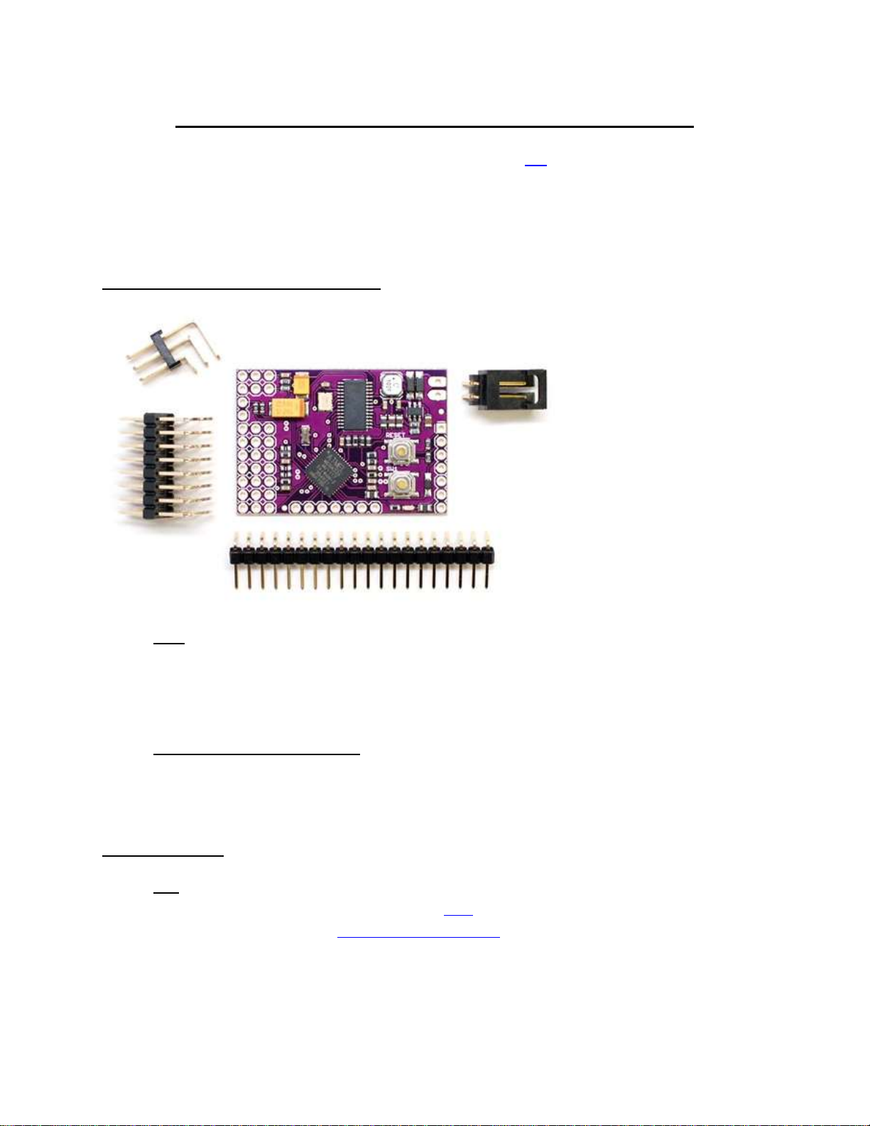
What your Remzibi’s OSD 3DR comes with:
Pins: all of the pins you will need to solder onto the board:
o (1) 3x8 header pins
o (1) 1x20 header pins
o (1) 3x2 header pins
o (1) battery adapter
DIY Drones Remzibi’s OSD cable: It's an FTDI cable, but with a 4-pin female header instead of
the usual 6-pin (this was done to keep compatibility with the OTI cable that the original Remzibi
used). You can also use your standard FTDI cable, but you will have to use some extra wires to
make the required connections. This will be covered later in the tutorial.
You will also need:
GPS Any GPS that uses serial can be used. In this tutorial, I will be using the MediaTek GPS with
basic adapter offered at the DIY Drones store here.
Important note: the DIY Drones Mediatek GPS comes with custom DIY Drones firmware
and must be programmed with the factory default firmware to work with the Remzibi’s OSD.
Updating the firmware is simple to do, and instructions for how to do this will be covered later
in this tutorial.
Page 2
Video Camera and transmitter/receiver check out rcgroups.com for more information on video
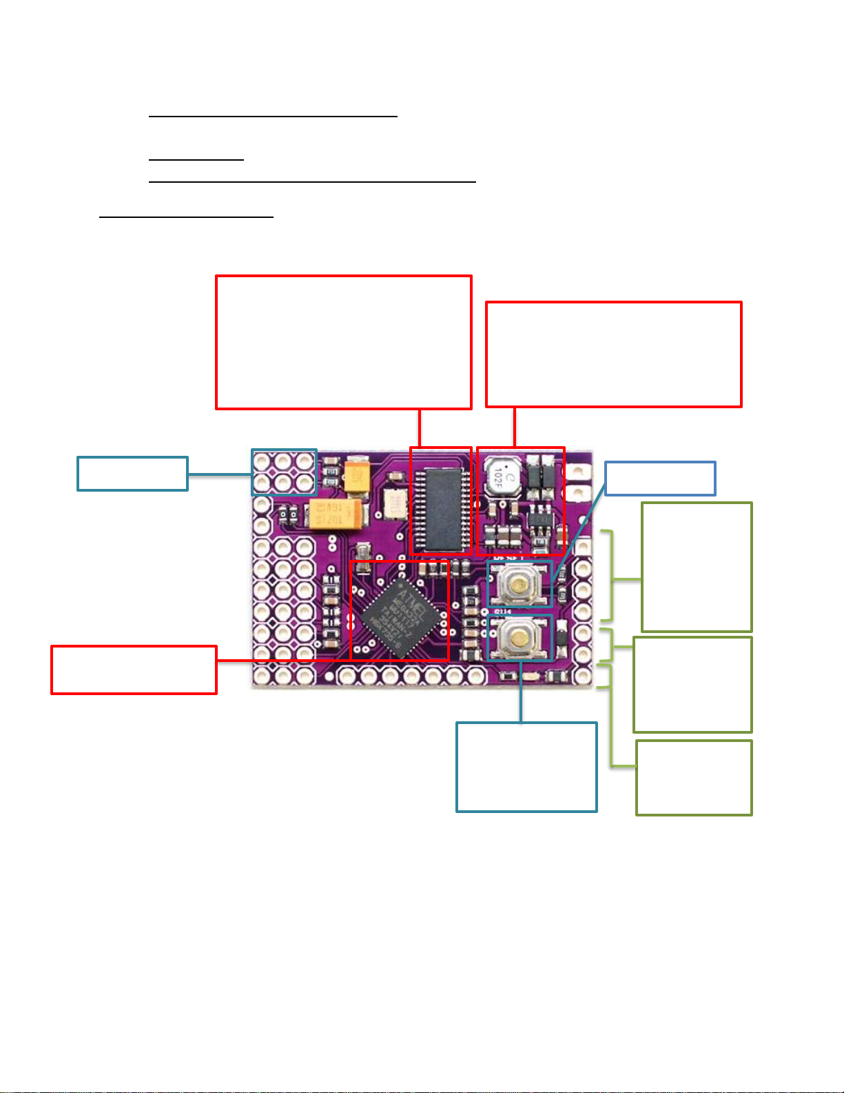
5V/600mA switching regulator
Reset Switch
SW1 Switch
modes
ATMEL Mega32A chip
MAX7456 Chip
And many user-defined settings!
Video In/Out
Serial Port
or connecting
RSSI
Measure radio
signal strength
Motor Battery
voltage
transmitters and receivers, and to learn more about FPV flight.
12 Volt Battery
R/C Plane well suited for FPV (ie Brushless EasyStar)
Details about the Hardware
Board measurements: 1.6 in x 1.1 in ( 4cm x 2.7cm)
256 User-defined characters or
pictographs
12x18 Pixel character size
New voltage regulator! It takes care
of the heating problem.
Used for GPS
to your
computer
Used to read
motor battery
Used for changing
Page 3
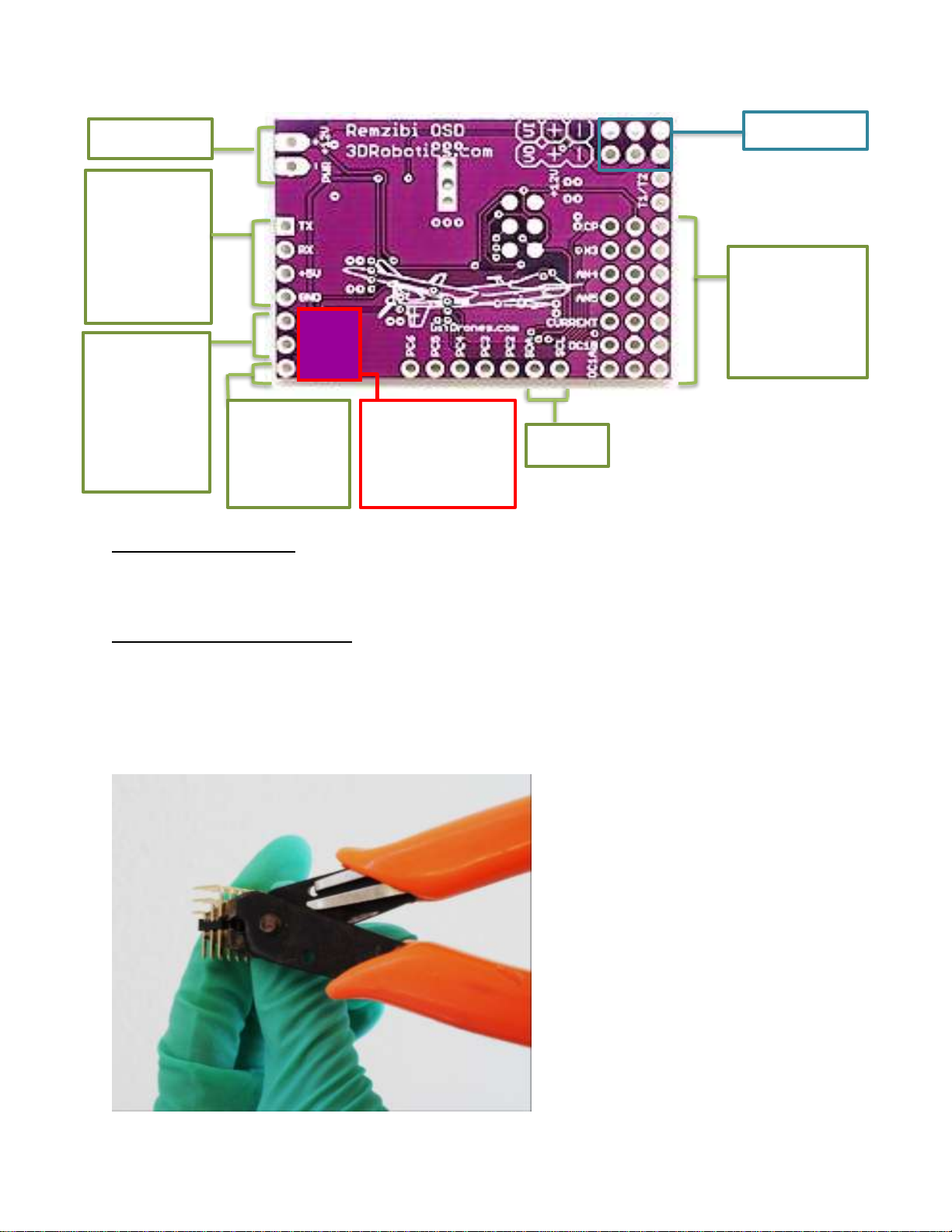
Serial Port
Used for GPS
computer
I2C port
ADC ports
and clock ports
Video In/Out
Battery
Motor
RSSI
strength
+
RSSI
Silkscreen
or connecting
to your
(“AN3”-“AN5”
& “CURRENT”)
―
Battery
Used to read
motor battery
voltage
Measure
radio signal
correction for the
release version
Important Revision Note: The release version of the Remzibi’s OSD 3DR, has an error on the silk screen
label on the back side of the board: the silkscreen currently reads "-, +, RSSI" when it should be "RSSI, -,
+". This correction is shown above. Please be aware of this before you use the product.
Assembling Remzibi’s OSD 3DR
You will need to cut away some of the spare pins that came with your Remzibi’s OSD 3DR. Cut two sets
of 7 pins and one set of 2 pins from the row of 20 right angle header pins. You will have 4 pins left over.
Save them for another project! You will only need 7 rows from the block of 3x8 right angle header pins,
so you can carefully cut off one row of pins:
Page 4
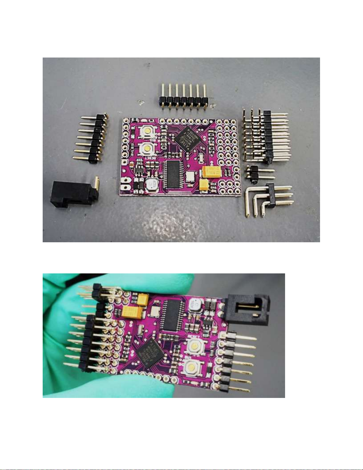
Here I have all of the pins cut and set next to the pads I will be soldering them to on the Remzibi board:
Carefully solder the pins onto the board. I did not solder the SCL-PC6 pins yet, but here is my Remzibi’s
OSD with all of the other pins soldered on:
Page 5
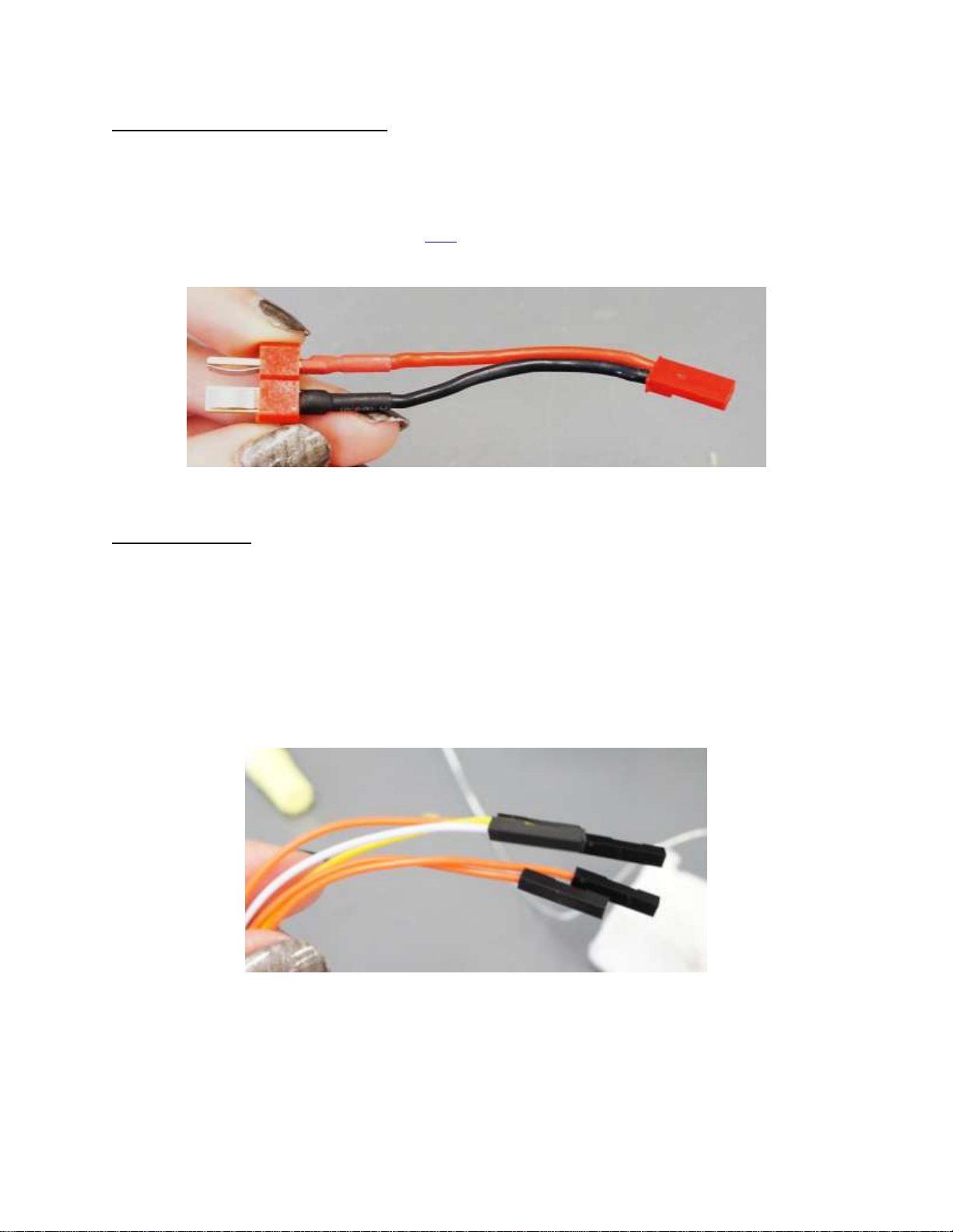
Soldering a Connector for Your Battery
Female Connector Jumper Cables
Battery Adapter for Deans Connector
If you’re using a connector for your battery that is not compatible with the connector that comes with
the Remzibi’s OSD 3DR, making your own adapter is simple. You can use a JST female connector, or strip
a jumper cable with 2 pin female connector and solder it to a connector that corresponds to your
battery. Here is the adapter I used (available here) with a JST female connector and a Deans male
connector:
Connecting the GPS
You will need a GPS with serial (RX/TX) port. The GPS connects to the serial port on the Remzibi’s OSD
3Dr. This is the same port used for the FTDI cable, and it is labeled “TX RX +5V GND”. Since the serial
pins are also used for connecting your Remzibi’s OSD 3DR board to your computer, you may not want to
solder the GPS permanently onto the board. You can solder pins to your Mediatek GPS and use jumper
cables to connect it to the Remzibi’s OSD 3DR so the GPS can be removed when you need to connect the
Remzibi’s OSD board to a computer. I stripped one end of 4 jumper cables with female connectors and
soldered them directly to my MediaTek GPS:
Page 6

Female Connector Jumper Cables soldered to the +5V / GND /
In
Out
+5V
Gnd
GPS
How to connect your GPS:
OUT / IN pads on the MediaTek GPS
This concludes the Assembly portion of the tutorial!
Next: How to flash your DIY Drones Mediatek GPS with the factory firmware!
Page 7

DIY Drones Mediatek GPS
Black
Red
Orange
Yellow
GND
OUT
IN
Remzibi’s OSD 3DR Cable
How to connect Mediatek GPS to Remzibi’s OSD 3DR cable:
The DIY Drones Mediatek GPS comes with custom DIY Drones firmware for use with the ArduPilot Mega
system. To use the Mediatek GPS with your Remzibi’s OSD 3DR, you will need to change the GPS
firmware to the factory default firmware.
What You Will Need
You can use the Remzibi’s OSD 3DR cable that came with your Remzibi’s OSD to connect your GPS to the
computer. You may need jumper cables and pins. You will also need to download the firmware update
utility available for free online here.
Connecting Your GPS to Your Computer
Connect your GPS to the Remzibi’s OSD 3DR Cable as shown. Notice that the orange and yellow lines are
crossed so that Orange cable in the Remzibi’s OSD 3DR Cable connects to “IN” and the yellow cable
connects to “OUT.”
5V
Page 8

Uploading the Firmware
Download the firmware update utility found here and unzip the file. Download the factory default
firmware found in the Mediatek GPS product description here, and save the firmware “.bin” file to a
handy location, such as the firmware folder for the firmware update utility. Follow the instructions in
the MediaTek_Programming.pdf document.
Note: With the factory default firmware, the blue “3D FIX” light on the Mediatek GPS will blink until the
GPS has a satellite lock, and the light will go solid once the GPS has locked. This is the same as for the
DIY Drones firmware.
Now your Mediatek GPS is ready to use with Remzibi’s OSD 3DR!
Next: How to operate the Remzibi’s OSD 3DR with DIY Drones version firmware!
Page 9

Powering the Board
Video Input/Output
Battery
Remzibi’s OSD 3DR must be powered externally with 12V. To power your board, just plug your 12V
battery into the PWR +12V pins. The board will not be powered from the computer via the DIY Drones
Remzibi’s OSD 3DR cable.
Unlike with the Original Remzibi’s OSD, the video camera and video transmitter can be powered directly
from the Remzibi’s OSD 3DR board. The video input and output pins include +12V pins which can be
used to power your camera and video transmitter directly from the board.
Connecting Video Equipment
The OSD board is placed between the video camera and the video transmitter on the R/C plane. There
are typically 3 wires that connect these two components. A red wire for power (for example, 5V or
12V), a black wire which is ground and a white wire which is the video signal. Remember that unlike with
the Original Remzibi’s OSD, the video camera and video transmitter can be powered directly from the
Remzibi’s OSD 3DR board, so if your video equipment uses 12V, you do not need to make a custom
cable for powering the camera and video transmitter. If your video equipment requires something other
than 12V, you may need to use a voltage regulator or a separate battery to power it.
Page 10

Connecting your Remzibi’s OSD 3DR to your computer
Yellow
Orange
Red
Black
TX
+5V
GND
Remzibi’s OSD 3DR Cable
or standard FTDI cable
The Remzibi’s OSD 3DR is connected to your computer using the DIY Drones Remzibi’s OSD cable. Black
is GND and Yellow is TX.
RX
You will also need to power the Remzibi’s OSD 3DR board with an external 12 V power supply (See the
“Powering the Board” section earlier in this tutorial).
Changing Modes, and the Meaning of the Status LED
Your Remzibi’s OSD 3DR has two modes: Normal mode, and Manual mode. For more information on
Normal mode and Manual mode, refer to Happy Killmore’s manual (link).
Normal Mode: By default when you power your Remzibi’s OSD 3DR board, it will be in Normal
mode, and you will notice that the blue status LED is blinking. In Normal mode, your Remzibi’s
OSD has two video modes: PAL mode and NTSC mode. The mode your Remzibi’s OSD 3DR is set
to will be displayed next to “Video init” on your screen when you power the Remzibi, and will
either read PAL or NTSC. To switch between NTSC mode and PAL mode, press and hold the SW1
until you see the mode change on your video screen. To “Save Home,” press the SW1 switch.
Programming Mode: Unlike the Original Remzibi’s OSD which has a red button for switching
between modes when the board is powered, on the Remzibi’s OSD 3DR, the SW1 switch is used
to switch from Normal mode to Programming mode. In Happy Killmore’s manual, whenever you
are prompted to switch to Programming mode, this is how you can do this: Hold down the SW1
switch while you power the board or hold down the SW1 switch while you reset the board to
Page 11

switch the mode. When the board is in programming mode, the blue LED will be solid. If the
Status LED
What it Means
Blinking
Remzibi’s OSD 3DR is in Normal Mode
Solid (after pressing SW1 and resetting)
Remzibi’s OSD 3DR is in Programming Mode
Remzibi’s OSD 3DR board’s video output is hooked up to a screen, you will see the character set
currently on the board displayed on the screen.
Important note: The SW1 switch may not have the same functions if you are using firmware
versions other than the DIY Drones version firmware. The Status LED may also not have the
same function, or may not turn on at all, if you are using versions other than the DIY Drones
version firmware.
Meaning of the Status LED
Page 12

Testing the Serial Connection
Connect your Remzibi’s OSD 3DR to your computer (see the “Connecting your Remzibi’s OSD 3DR to
your computer” section earlier in this tutorial)
To test the serial connection, you will need to switch to Programming mode (See the “Changing Modes,
and Meaning of the Status LED” section earlier in this tutorial). Once the OSD is in Programming mode,
click on Serial Communications.
In the Serial Functions window, select
the correct COM port, and click
Connect. In the Serial Cable Setup tab,
select “FTDI – diydrones.com”
from the Cable Selection dropdown
menu. You do not need to follow the
Programming Mode instructions listed
in the window since these are for use
with the Original Remzibi’s OSD. Click
Start Test, and check that the Status
reads “Passed […]” If the test fails, make
sure you have selected the correct COM
Port, make sure that your Remzibi
board is in programming mode, and
check your cabling. Also make sure that
the Remzibi board is powered.
Upload Program & Font
Your Remzibi’s OSD 3DR will need to be in programming mode (see the Changing Modes, and the
Meaning of the Status LED” section earlier in this tutorial). The rest of the steps for uploading program
and font are the same as the steps in Happy Killmore’s manual (link) for the Original Remzibi’s OSD.
Page 13

Updating Firmware
Your Remzibi’s OSD 3DR comes with the latest DIY Drones version of the firmware, and character set
already loaded. We recommend using the DIY Drones version firmware since this makes use of the
status LED, SW1 switch, and other features of the 3DR version Remzibi’s OSD, but if you would like to
change the firmware or update it when new firmware is released here’s how you can do this using the
Remzibi’s OSD Configuration Tool PC Software:
First, connect your Remzibi’s OSD 3DR to your computer (see
the “Connecting your Remzibi’s OSD 3DR to your computer”
section earlier in this tutorial)
1. In the Firmware Update window, choose the source
firmware you would like to upload. If you do not see the
firmware you would like to upload in the dropdown
menu, you can search for it in the next window.
2. click on MegaLOAD
3. In the MegaLOAD window, you may see a file under File
to be programed in the Flash. You can either upload this
firmware, or you can search for a different firmware by
clicking Open and searching for the File to be
programmed in the Flash.
4. Select the COM port
5. Set the Speed to 38400bps
6. Press the reset button on
the Remzibi’s OSD 3DR to
reset the board. The
firmware will automatically
be uploaded. If the upload
fails or does not begin
immediately, try resetting
the board again.
7. When the firmware is being
uploaded, you will see
pages being sent in the
Messages box, and once it
is finished, it will read
“Flash Prog done!”
Page 14

This concludes the Remzibi’s OSD 3DR tutorial.
Thank you for reading! Please send any feedback regarding this tutorial to Carmen at
help@3drobotics.com. Feedback is always welcome and appreciated.
 Loading...