

Page 1

IMPROVEMENT UPDATE
PIXHAWK ADJUSTMENT
V.A
2014
Contents
It has come to our attention that, in some cases, the electronics inside Iris can become
positioned in a way that wears on the connections between the components. To ensure
that this issue doesn’t aect your Iris’s autopilot system, follow these instructions to
adjust the position of Pixhawk.
For a video tutorial of this process and for more information, visit 3dr.com/iris/info.
Parts
Tools
1 Cut out guide
2 Remove top shell
3 Re-position Pixhawk
4 Replace top shell
5 Re-calibrate Iris
1
1
1
2
2
4
5
Page 2
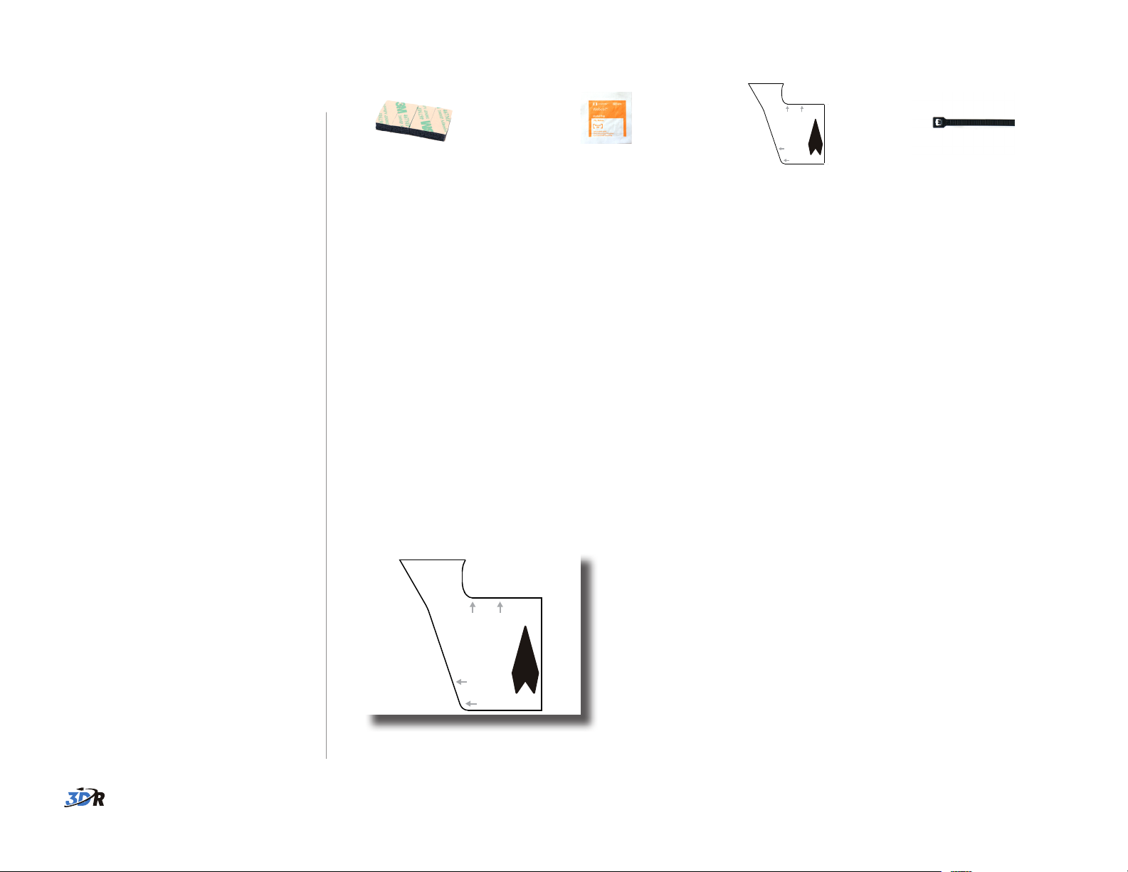
Parts
Align with top-right
corner of Pixhawk.
Align with
back-left
corner of
plate.
Align with top-right
corner of Pixhawk.
Align with
back-left
corner of
plate.
Align with top-right
corner of Pixhawk.
Align with
back-left
corner of
plate.
Align with top-right
corner of Pixhawk.
Align with
back-left
corner of
plate.
Tools
Align with top-right
corner of Pixhawk.
Align with
back-left
corner of
plate.
foam cleaning pad guide zip tie
To complete this update, you will need the following tools:
• medium hex key, 2 mm (included with Iris)
• flat-head screwdriver or other small, flat prying tool (not included)
• scissors (not included)
1 Cut out guide
Cut out the shape of the guide
provided with this kit.
Align with top-right
corner of Pixhawk.
Align with
back-left
corner of
plate.
1
Page 3

2 Remove top
shell
Place Iris upside down with the
battery door open. Using the
medium hex key, remove the screw
inside the battery compartment. On
the front end of Iris, remove the two
deep-set screws on either side of the
camera mount.
Holding the shell together, turn Iris
over and open the top shell.
Remove screws.
3 Re-position
Pixhawk
During this process, try not to stress
any of the cable connections between
the components.
1 Pull Pixhawk away from plate.
Pull Pixhawk o the foam squares
and slightly away from the plate.
Remove the remaining foam from
the bottom of Pixhawk and the top
of the plate. Use the cleaning pad to
remove any dust from the surface of
the plate.
Open shell.
Remove foam from Pixhawk and plate.
Some adhesive residue may remain on the plate.
2
Page 4

2 Attach foam to Pixhawk.
Separate the four foam squares, and
remove the adhesive backing from
one side. Place one square onto each
corner of the bottom of Pixhawk
without disconnecting any of the
cables.
3 Align guide to plate.
Place the guide over the back-left
corner of the plate as shown. It may
be helpful to tape the guide in place.
Be very careful when completing these steps! The adhesive on the foam will
only stick once, so make sure to place the pieces carefully the first time.
example of foam attached
to the bottom of Pixhawk
4 Check position of splitter.
Align the top-right corner of Pixhawk
with the guide. If the I2C splitter is
touching Pixhawk, complete this step
to adjust its position.
Use a flat-head screwdriver or similar
tool to wedge the splitter and
adhesive gently away from the plate.
To avoid damaging the splitter, do not
use too much force or put pressure
on the connectors.
Move the splitter a few millimeters
away from Pixhawk so that it won’t
touch the board in its new position.
The splitter may overlap slightly onto
the cutout in the plate as long as it
can stick securely in place.
I2C splitter
If the splitter touches Pixhawk in its new
position, use a tool to adjust the position of
the splitter so that it has a few millimeters
of clearance between the two components
as shown.
Pixhawk situated in the correct position,
aligned with the guide, with the proper
clearance for the splitter
3
Page 5

5 Attach Pixhawk to plate.
Remove the remaining backing from
the foam squares and stick Pixhawk
in place, aligned with the guide.
Remove the guide from the plate.
final assembly
6 Zip tie cables.
To the right of Pixhawk, zip tie the
cables together so that they sit on
top of the telemetry radio and do not
become pinched between Pixhawk
and the telemetry radio.
7 Check components.
Check that the splitter, telemetry
radio, and other components do not
touch Pixhawk.
4 Replace top
shell
Reverse the process in step 2 to
replace the top shell. Make sure that
the shell does not pinch any of the
cables.
Zip tie cables on top of
telemetry radio.
Check that Pixhawk doesn’t
touch any other components.
Close shell, making sure not to pinch cables.
Replace screws.
4
Page 6

5 Re-calibrate
Connect to Mission Planner/APM Planner, select Initial Setup and Mandatory
Hardware, and follow the prompts to perform the following calibrations:
Iris
Now that you’ve re-positioned
Pixhawk, re-calibrate the compass
and accelerometer for the new
configuration.
1 Power on transmitter, and connect
telemetry radio to computer using
the micro-USB cable.
2 Connect battery to Iris. Do not
press the safety button!
3 Connect to Mission Planner or
APM Planner by selecting the
available COM port and setting the
rate to 57600.
4 Select Initial Setup and Mandatory
Hardware.
1 Compass
2 Accelerometer
View calibration
video tutorials at
3dr.com/iris/info!
Select Pixhawk.
If prompted for firmware version over 3.01, select Yes.
Select Live Calibration.
Move Iris around all axes.
Select Done after collecting data points for all positions.
5 Perform compass and
accelerometer calibrations.
Do not complete the setup wizard.
Only the two calibrations specified
here are required. If the wizard
appears, close it, and select Initial
Setup and Mandatory Hardware to
view individual calibrations.
Select Calibrate Accel, and
follow the prompts.
The update is now complete!
For customer support, contact us at help@3dr.com or call our support line at
+1 (858) 225-1414 Monday through Friday, from 8 am to 5 pm, PST.
5
 Loading...