

Page 1

Aero-M
Operation Manual
Thank you for purchasing an Aero-M! This manual contains important information about your
aerial mapping platform. Please read these instructions before your first flight.
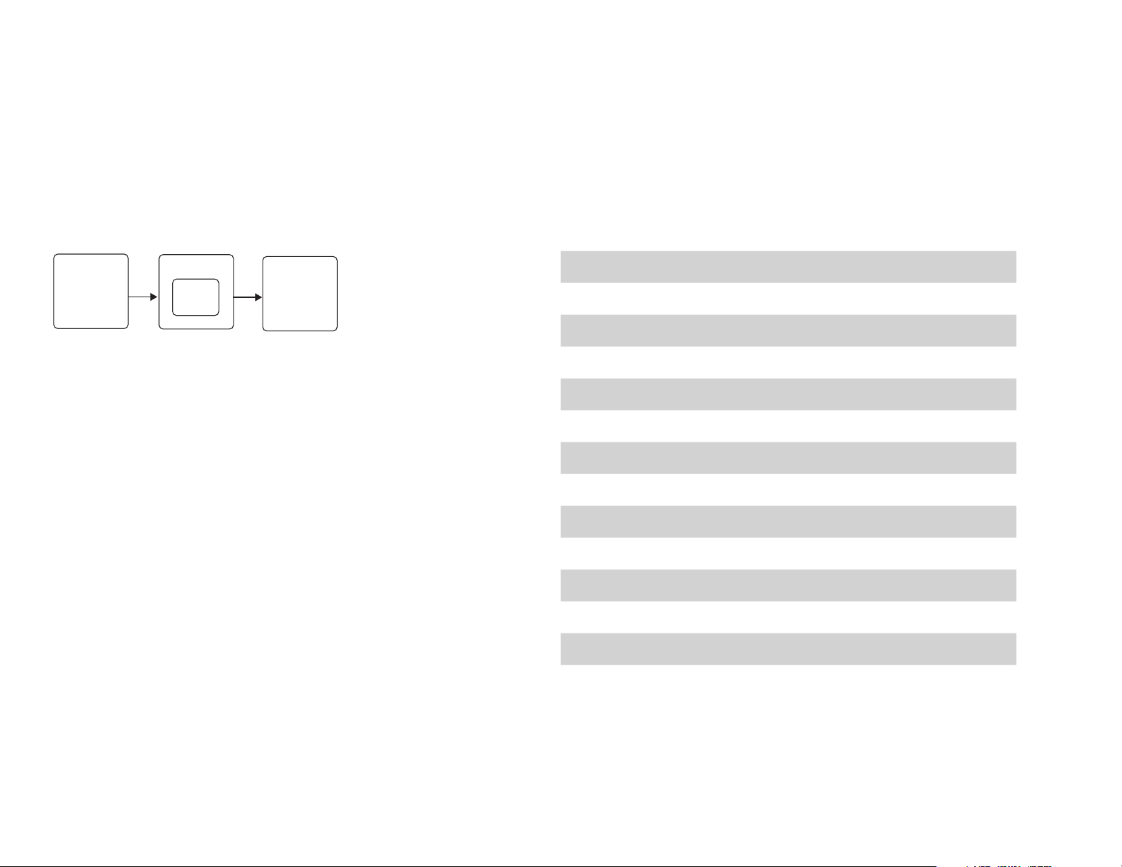
1 Plan 1
2 Fly 20
3 Process 37
Appendix 41
Online information portal: 3DR.com/Aero-M
3DR support: help@3DR.com
Terms and conditions: 3DR.com/terms
Pix4D instructions: support.Pix4D.com
V.1 2014
©3D Robotics
DCT0010
Page 2

1 Plan
Parts 2
Flight Battery 3
Charging 3
Safety 3
Powering the Aero 4
Camera Setup 5
3DR EAI 5
Charging 5
Starting a Mission 5
Mounting 6
Ground Station Setup 7
Download Software 7
Connect to Radio 7
Mission Planning 8
Operating Parameters 8
Load Maps 9
Draw Polygon 10
Configure Survey 11
Save and Write Mission 19
1
Page 3

Parts
RC controller and
accessories
Aero
batteries (2)
camera
wing spar
horizontal stabilizer
wings
ground station radio
micro-USB cable
charger and
accessories
battery guard bag
wing rubber bands
(4 plus 2 spare)
propellers (1
plus 1 spare)
hex keys (?)
registration card and
Pix4D license key
FPV/OSD System
If you selected to receive a FPV/OSD system, those components
will be included with the Aero’s accessories. See page 34 for
parts and instructions.
propeller wrench
spare control horns
(2)
spare servo rods (2)
spare camera
mount filters (2)
Pixhawk micro-SD
card adapter
2
Page 4
Flight Battery
The Aero is powered by a rechargeable lithium polymer (LiPo) battery.
Charge the battery before your first flight.
Charging Safety
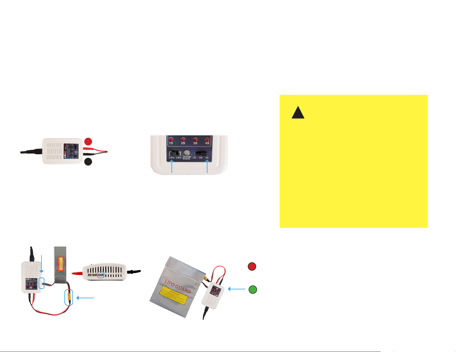
1
Connect the charger to the power adapter cable
and a wall outlet. Connect the red cable to the +
port and the black cable to the - port.
+
–
Charger with power cable and
split-wire charging cable
3
Connect the white connector to the 4S port, and
join the two yellow connectors together.
2
Set the charger to LiPo and 3A.
LiPo
Charger settings
4
Secure the battery inside the guard bag,
and charge until the status indicator
displays green.
3A
!
Flying with a low battery is a safety risk and can render the
battery permanently unusable. Always fly with a fully charged
battery.
Charge the battery using a designated LiPo balance charger
only. Always monitor the battery while charging. Protect the
battery from extreme heat, extreme cold, puncturing, and
flammable surfaces. Always transport, charge, and store the
battery in the guard bag.
Inspect the battery for damage before and after flying. If you
observe any swelling of the package or the battery ceases
to function, do not use the battery; locate your local battery
recycling center, and dispose of the battery. In the US and
Canada, visit call2recycle.org to find a location. Do not
dispose of the battery in the trash.
4S
Flight battery charging wiring Charging in process
Charging
Complete
3
Page 5
Powering the Aero
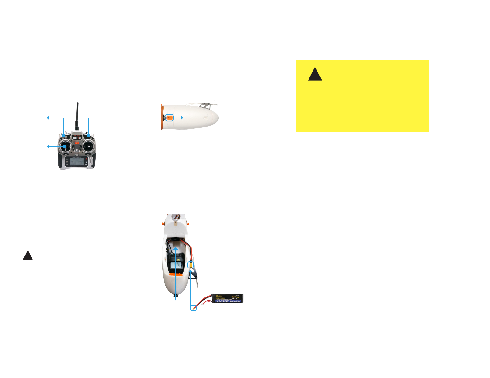
1
Turn on the controller. To avoid triggering
the controller’s startup alarm, ensure that
all switches are set back (away from you)
and the throttle stick is set fully down.
Switches
Throttle stick
RC controller
3
Insert a charged battery into the battery slot,
and attach the yellow connectors. This will
power on the Aero.
2
Open the battery compartment by
sliding the knob on the orange switch
forward and lifting out the lid.
Aero: battery compartment lid
!
It is important to establish communication before
powering on the Aero. Always turn on the controller
before connecting the battery. When powering off
the Aero, disconnect the battery before turning off
the controller.
!
Hold the Aero still and level while it powers on.
Attach the velcro above the battery slot to the
velcro on the battery. Close and secure the lid
onto the battery compartment.
battery
connector
battery slot
Aero: battery compartment interior
flight battery
4
Page 6

Camera Setup
The Aero includes a Canon PowerShot SX260 HS running the 3DR EAI script.
3DR EAI (Exposure-Aperture-ISO)
3DR EAI runs on the Canon Hacker Development Kit (CHDK), a powerful opensource tool that expands the functionality of Canon point-and-shoot cameras. 3DR
EAI optimizes image exposure and integrates with the Pixhawk autopilot to enable
distance-based imaging.
This software is designed to load off the camera’s SD card, leaving the original Canon
programming intact. The yellow switch on the side of the SD card allows you to lock
or unlock the card. Lock the SD card to run 3DR EAI; unlock the SD card to save
images to your ground station or to boot the camera with its original programming.
For more information about 3DR EAI, see page 43.
SD card locked
Load 3DR EAI
» Fly a mapping mission
SD card unlocked
Load default Canon software
» View images on camera
» Save images to ground station
» Update script
Charging
Charge the camera battery before your first flight. Once
fully charged, insert the battery into the camera.
status indicator
Canon battery charger
Starting a Mission
To prepare the camera to fly a mapping mission, ensure
that the mode dial is set to P (program) mode. Power on the
camera using the silver button on the top. 3DR EAI will start
automatically, and you will see the script messages on the
camera display. Check to see that the last line of the script
reads waiting on USB signal. The camera is now ready to map!
Camera running 3DR EAI Camera running Canon software
Power off the camera before removing the SD card.
!
power button
mode dial
Camera ready to map: waiting on USB signal
5
Page 7
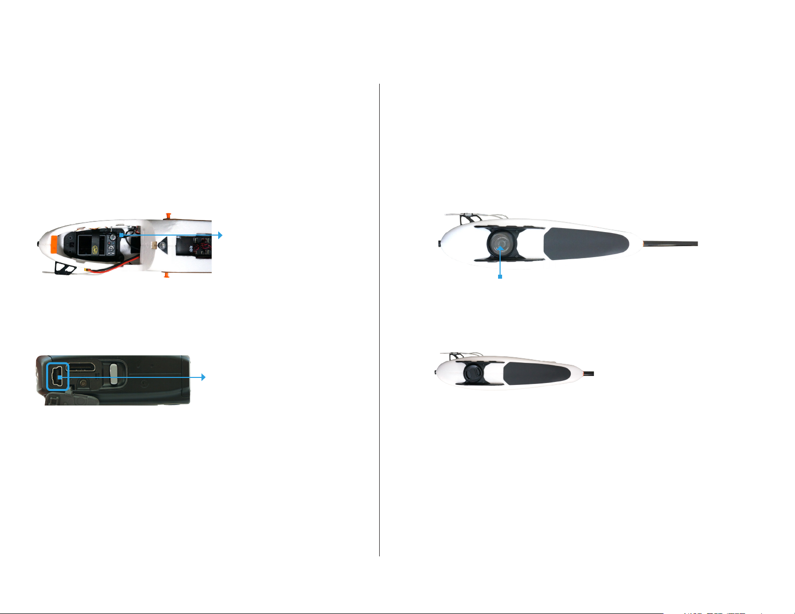
Mounting
The camera mounts to the Aero inside the battery compartment
and connects to the autopilot using the mini-USB cable. When the
camera is ready to start the mission, insert the camera into the
mount inside the battery compartment as shown below, connect
the mini-USB cable to the camera, and secure the camera in place
using the velcro strap.
autopilot integration cable
Aero battery compartment: camera mount
Connect mini-USB cable inside
battery compartment here.
The camera mount includes a lens cap that protects the filter during
travel. Make sure to remove this lens cap before you fly, and check
that the filter contains no foam particles, dirt, or scratches that could
affect image quality.
It is expected that the filter will accumulate scratches after significant
use. If you notice any damage to the filter that could affect image
quality, unscrew the filter and replace with one of the extra filters
provided with the Aero.
UV filter
Camera mount (bottom): cap removed
Camera (side)
The camera mount is fixed to the inside of the battery compartment
and is not intended to be removed from the Aero.
Camera mount (bottom): cap attached
6
Page 8
Ground Station Setup
Mission Planner allows you to turn a Windows laptop into a full-featured
ground station for configuring and monitoring autonomous missions. You will
need to take this laptop into the field when you fly the mission. As part of the
mission procedure, you will use the Pix4D Rapid Check to verify the quality of
the image set before leaving the field.
Connect to RadioDownload Software
Mission Planner
Mission Planner is a full-featured ground station application for planning
missions and monitoring the Aero in flight. Download Mission Planner
from 3DR.com/download_software.
If you already have Mission Planner installed, make sure you’re running
the most recent version: Select the Help tab and Check for Updates.
Mission Planner: Help tab
Pix4Dmapper LT 3DR Edition
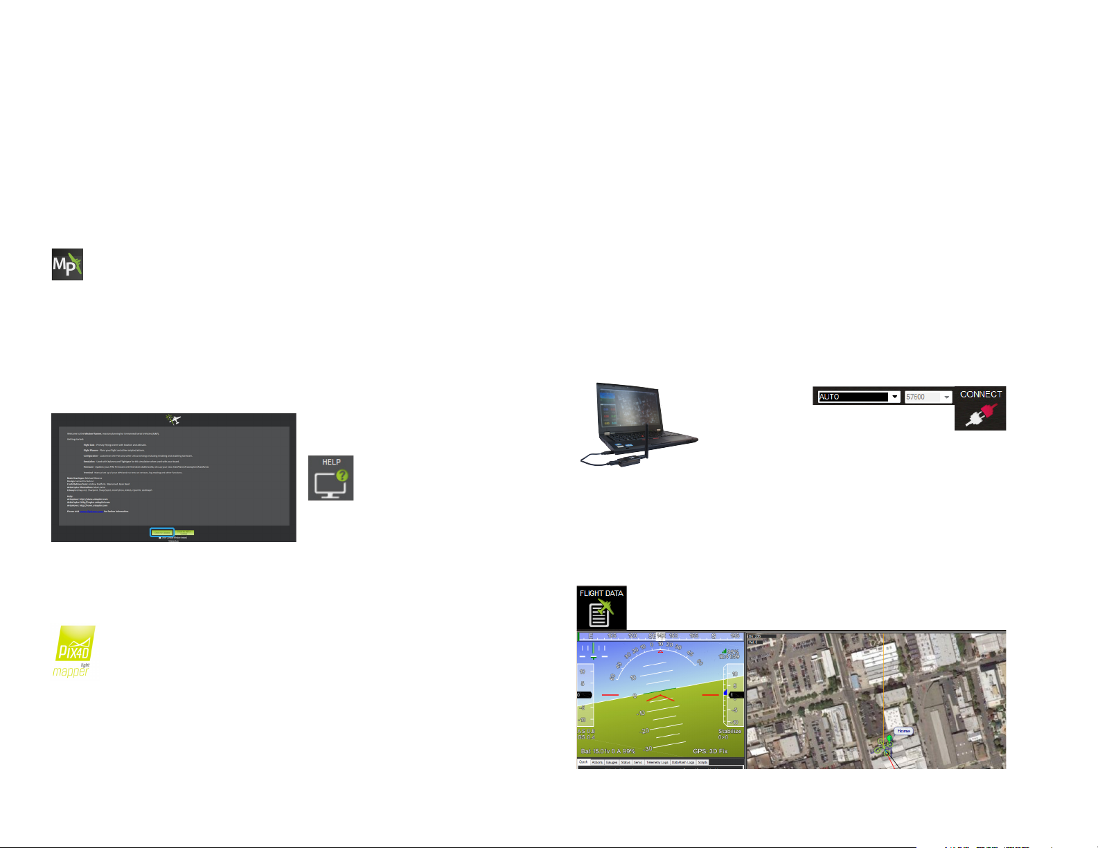
To connect the Aero to Mission Planner, connect the ground station radio
to the laptop, and power the Aero.
1
Connect the ground station radio to your
laptop using the micro-USB cable. Open
Mission Planner.
Ground station laptop with radio connected
3
Select Flight Data to view live data from the Aero.
2
Select 57600 and AUTO, then select CONNECT.
(When connecting directly to Pixhawk’s
micro-USB port, set the rate to 115200.)
Mission Planner Connect tool (top-right corner))
Your license key for Pix4Dmapper can be found on the registration card
inside the documents package.
Visit mapper.pix4d.com/license-redeem to create an account and redeem
your license key; then visit pix4d.com/download to download Pix4Dmapper
Discovery. Pix4D will automatically upgrade from the Discovery edition to
the LT 3DR Edition (or Pro Edition if you selected to upgrade) when you
log in to the program with your Pix4D account information.
Mission Planner Flight Data tab: connected to aircraft
7
Page 9
Mission Planning
Operating Parameters
The Aero is a complete solution for creating
high-resolution visual-spectrum aerial maps.
Canon SX260
Pixhawk
autopilot
system
Mapping system diagram
To create a map, the Aero flies an autonomous mission over
the survey site, using the integration between the Pixhawk
autopilot and custom-programmed camera to capture images
at a consistent distance interval. Pix4Dmapper then stitches
these images together into a georeferenced, orthorectified
mosaic.
The accuracy of the map depends on the configuration of the
mission. Planning a mission that captures high-quality images
requires balancing the Aero’s operating parameters with the
environmental factors at the survey site.
3DR EAI
Pix4Dmapper
LT 3DR Edition
Operating Parameters
Camera Canon SX260
Camera Orientation Portrait (side facing forward)
Operating Altitude 80-120 m
Standard Operating Altitude 100 m
Low-Wind Conditions 0-6 m/s
High-Wind Conditions 7-10 m/s
Maximum Wind Conditions 10 m/s
Operating Speed 8-20 m/s
Default Speed 15 m/s
Estimated Maximum Flight Time 40 min
Estimated Ground Resolution 5 cm/pixel
Estimated Maximum Survey Area 1 km
2
Minimum Photo Interval 2 seconds
8
Page 10

Load Maps
Mission Planner allows you to plan the mission away from the mapping location;
however, it is important to assess the environmental conditions on site at the time
of the mission and adjust the flight plan if necessary. Alternatively, you can plan
the entire mission at the mapping location. To create or alter the mission, Mission
Planner requires an Internet connection to access the maps. If you’re unable to
access the Internet on site, follow the instructions below to pre-fetch the maps
within Mission Planner while you have Internet access.
1
Open Mission Planner, select Flight Plan, and
zoom to your flying location.
Mission Planner Flight Plan tab: zoom to mapping location Mission Planner Flight Plan tab: Select Prefetch
3
Mission Planner will attempt to load the map data from the current level of zoom down to the
closest level of zoom available. However, it can take hours to pre-fetch every level of zoom,
and it is unlikely that the closer levels will be useful in planning the mission. To shortcut this
process, check the slider on the right side of the map. The levels of zoom are represented by
this slider from 0 (bottom) to 25 (top). Press the ESC key to skip levels of zoom at a greater
detail than you need for mission planning.
2
Right-click on the map, select Map Tool and
Prefetch, and accept the defaults prompts.
Mission Planner will download the maps
for the selected location to your computer.
9
Page 11
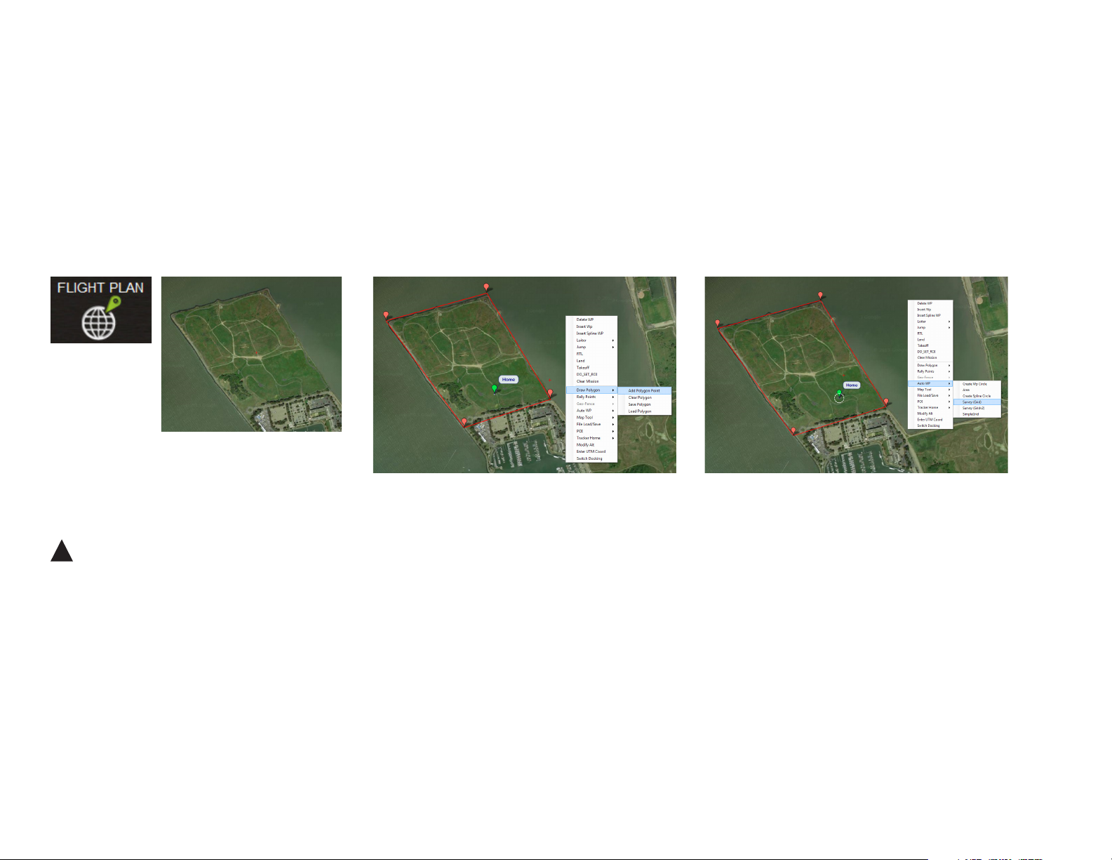
Draw Polygon
To begin planning the mapping mission, select the area you want to map using
the Polygon tool. You’ll be able to adjust the size and shape of the polygon later in
the mission configuration process.
1
Select Flight Plan, and zoom to your
mapping location.
Mission Planner Flight Plan tab: zoom to mapping location
!
Units
The Survey Tool uses metric units. If your Mission Planner is
set to imperial units, please change the settings to use metric
to plan the mission. Support for imperial units in Mission
Planner is coming soon; check 3DR.com/Aero-M for updates.
2
Right click on the map. Select Draw Polygon and
Add Polygon Point. Click and drag to add points
around the area you want to map.
Mission Planner Flight Plan tab: draw polygon
3
Right click on the polygon. Select Auto WP and
Survey (Grid) to open the Survey Tool.
Mission Planner Flight Plan tab: open Survey tool
10
Page 12
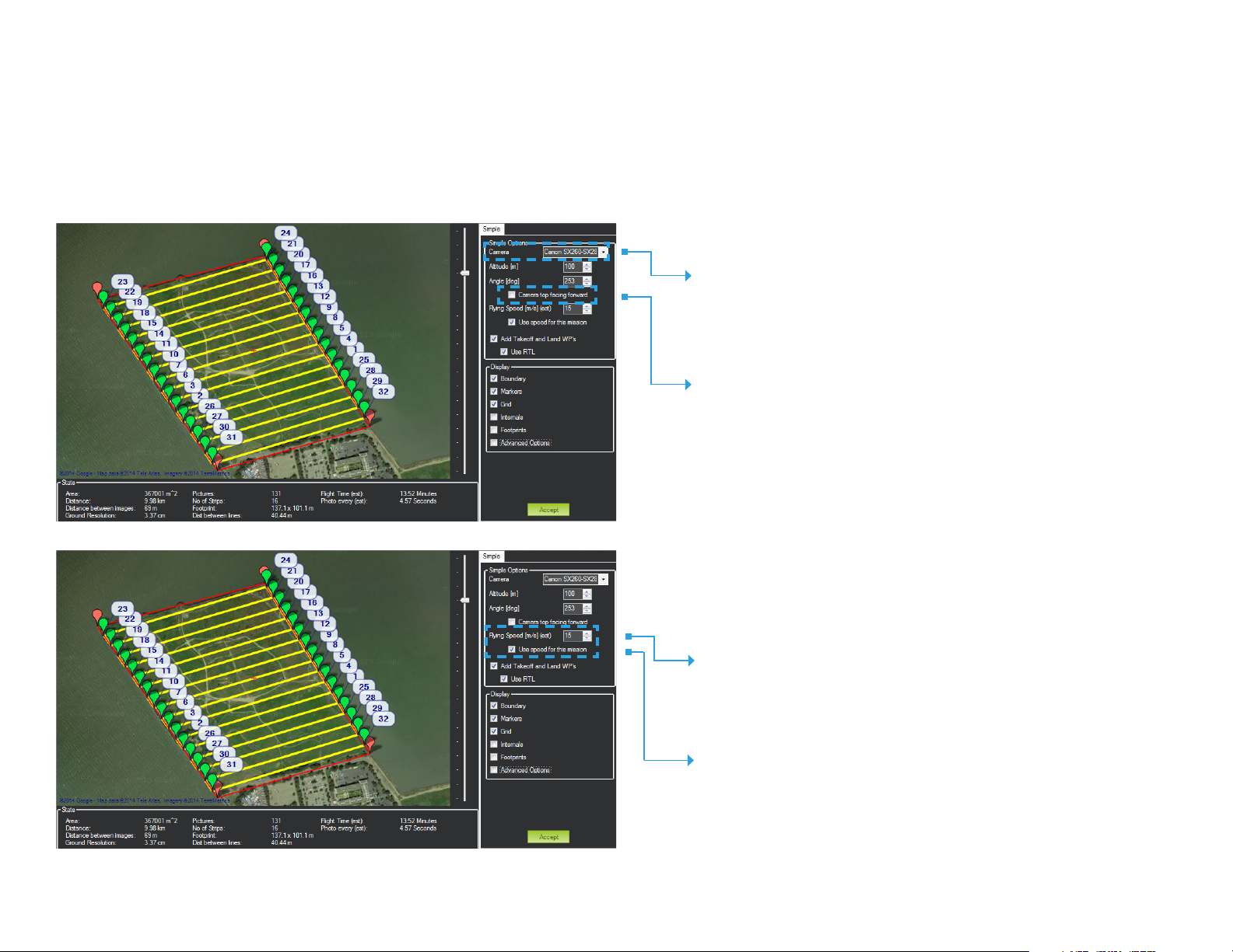
Configure Survey: Set Default Parameters
The Survey tool allows you to configure a mapping mission according to the
Aero’s operating parameters and the current environmental conditions at the
mapping location. First, set the default values for the Aero.
Set Camera
Canon SX260-SX280
Set Camera Orientation
Uncheck the option for Camera top
facing forward.
Mission Planner Survey tool
Set Default Speed
15 m/s
Apply Survey Speed
Check the option for Use speed for this mission.
If unchecked, the mission will use the Aero’s
default speed of 15 m/s regardless of the
speed selected in the Survey Tool.
11
Page 13
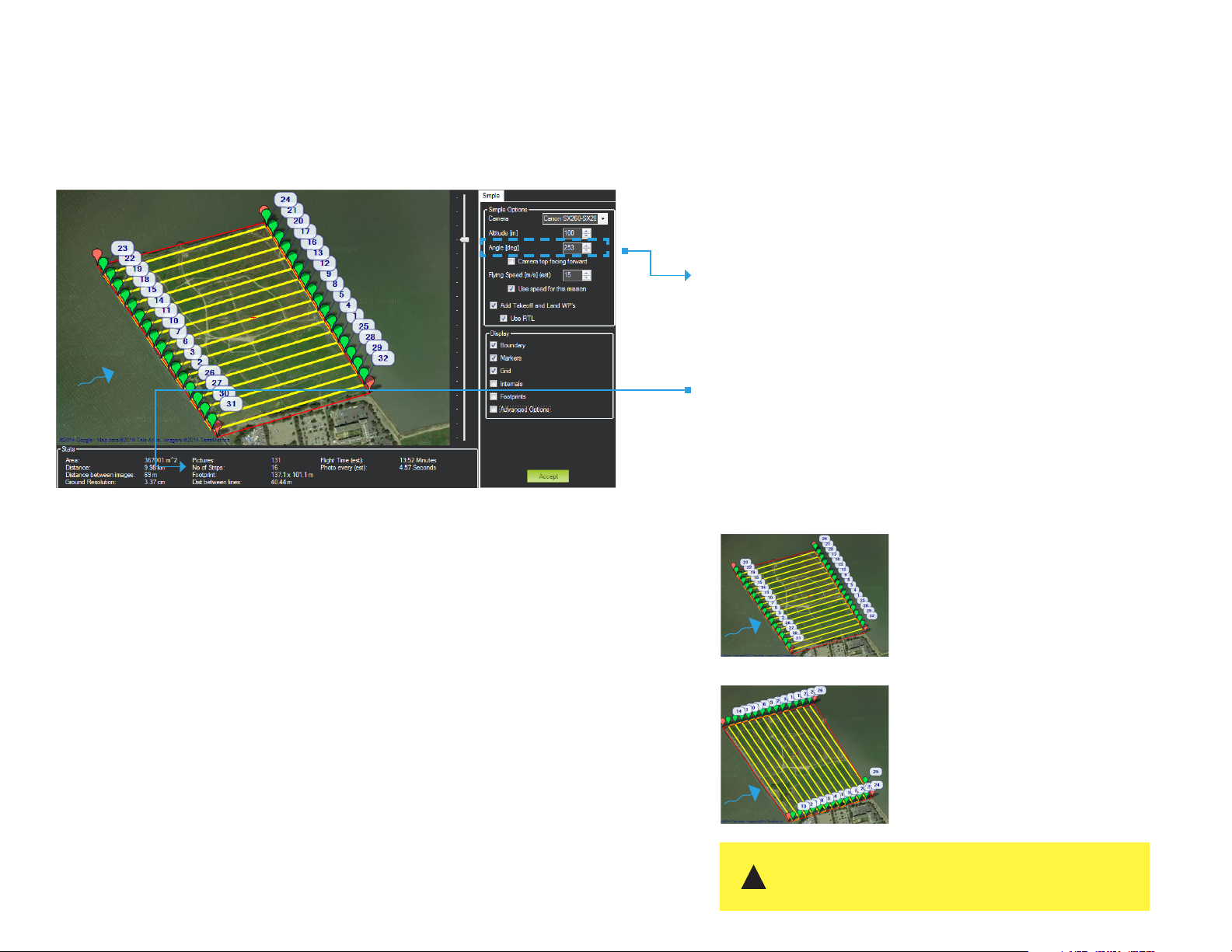
Configure Survey: Set Angle
Next configure the angle of the flight path for the current wind conditions.
Set Angle
Wind Direction
In environments with winds of less than 6 m/s, set the angle so that
the Aero flies into the wind. In winds from 7-10 m/s, configure the
flight path to travel perpendicular to the wind so the Aero flies crosswind.
wind
Mission Planner Survey tool
Mission Planner Tip: Adjust Polygon
Click and drag the red polygon points to adjust the size
and shape of the polygon from the Survey Tool.
No. of Strips
Adjust the angle so that the Aero makes as few turns as possible to
complete its course. The No. of Strips parameter shows how many
passes the plane will make as you adjust the angle.
Review Wind Conditions On-Site
Always assess the wind conditions at your survey site at the time of
the mission and adjust the mission accordingly.
Configure the flight path parallel with
the wind in low winds (1-6 m/s).
wind
Configure the flight path perpendicular to the
wind
wind in high winds (7-10 m/s).
Use caution when flying in winds over 10m/s. Mapping results
may degrade as a result of inability to make headway or maintain
!
appropriate groundspeed.
12
Page 14
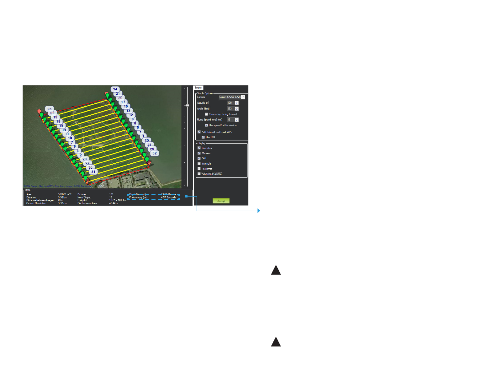
Configure Survey: Set Altitude
The survey altitude determines the duration of the mission and the ground
resolution of the final map. Adjust altitude to balance flight time and power
consumption with the current environmental conditions.
Mission Planner Survey tool
Set Altitude
Standard operating altitude: 100 m
Operating altitude range: 80-120 m
Increasing altitude decreases flight time, allowing you to cover more area
per minute. Decreasing altitude improves ground resolution. Set the altitude to get the best ground resolution while keeping the flight time under
40 min and the altitude under 120 m.
!
Keep altitude below 120 m, and ensure that the altitude is appropriate for
your flying area and local regulations.
Check Ground Resolution
Ground Resolution is the centimeters per pixel that you will have
in the map and corresponds to the amount of detail that you
will see.
To improve ground resolution by decreasing the number of
centimeters per pixel, decrease altitude.
Check Flight Time
Flight Time estimates the duration of the mission. The total estimated flight
time must be under 40 min for a fully charged Aero battery. To decrease
flight time, increase altitude or speed.
High winds, humidity, high altitude, and extreme heat can affect power
consumption and reduce flight time. Consider the environmental factors at
your site when configuring flight time.
13
Page 15
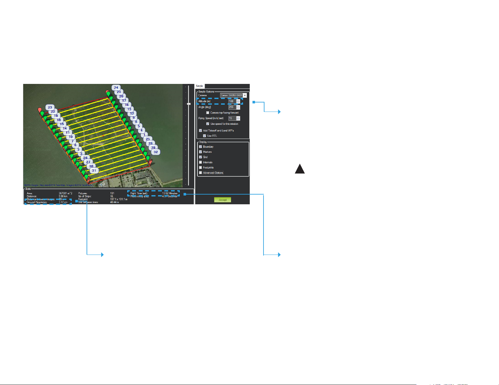
Configure Survey: Check Photo Interval
With the basic parameters in place, verify that the photo interval calculated from
the altitude and speed complies with the operating parameters for the camera.
Mission Planner Survey tool
Check Photo Interval
Photo Every must be longer than 2 seconds for the SX260 camera.
Altitude
Increasing altitude increases photo interval.
!
Keep altitude below 120 m, and ensure that the altitude is
appropriate for your flying area and local regulations.
Speed
Decreasing speed increases photo interval.
!
Ensure that the Use speed for this mission option is checked.
14
Page 16
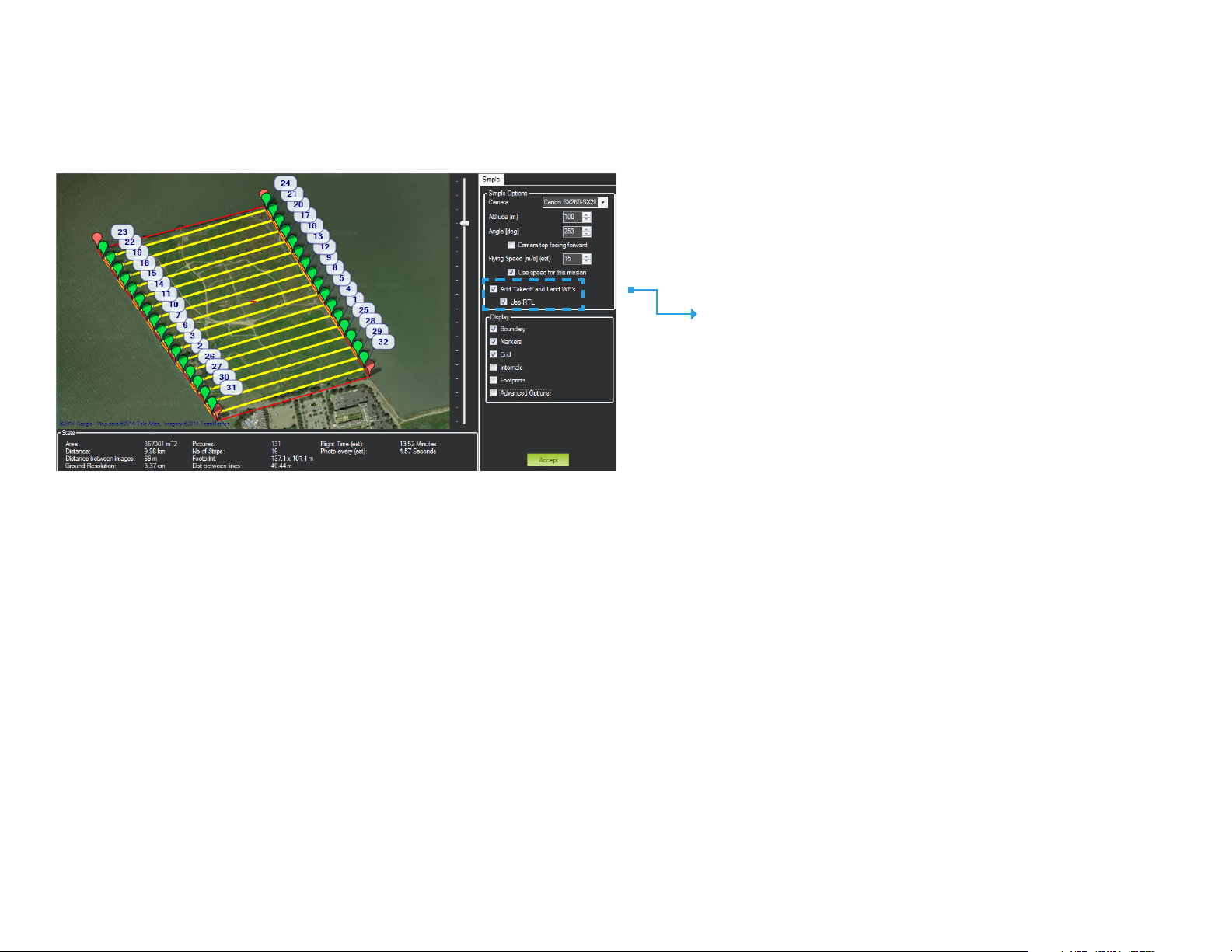
Configure Survey: Set Takeoff and Landing
Now select a takeoff and landing pattern, either manual or automatic.
Mission Planner Survey tool
Takeoff and Land WP’s
For automatic takeoff and landing
Check the Add Takeoff and Land WP’s option.
Uncheck the Use RTL option.
This will create a takeoff waypoint and a placeholder waypoint for the landing pattern. After accepting the survey, configure the automatic landing pattern by following
the instructions on page 20.
For automatic takeoff and manual landing
Check both the Add Takeoff and Land WP’s option and the Use RTL options.
This will create a takeoff waypoint so the Aero will automatically climb to the survey
altitude before heading to the first waypoint. The Aero will return to circle over the
launch point after completing the mission.
For manual takeoff and landing
Uncheck the Add Takeoff and Land WP’s option
Check the Use RTL option.
For this option, take off manually then initiate the mission in flight. The Aero will
return to circle over the launch point after completing the mission.
15
Page 17

Configure Survey: Advanced Options
The Survey tool includes the following advanced configuration options. These options
allow you to customize the mission to comply with best operating practices.
Check Advanced Options
to view the Survey Tool’s advanced configuration options.
Select Grid Options
Set OverShoot
The Aero has a minimum turning radius of 90 degrees. To accommodate the
sharp angles of the survey mission, set both OverShoot parameters to 50 to
have the Aero overshoot the waypoints on either side of the polygon by 50%
to ensure that the complete area of the polygon is covered by the images.
!
Mission Planner Survey tool: advanced options
Camera Config
The options under the Camera
Config tab allow you to configure
a camera other than the SX260
and won’t be used for operating
the Aero.
Mission Planner Survey tool: advanced options
OverShoot will affect flight time. Ensure that the total estimated flight time is
less than the Aero’s maximum flight time of 40 minutes.
Adjust StartFrom
During the mission, you will maintain contact with the aircraft through the RC
controller and ground station signals. If your mission is likely to experience a
loss of signal, it is best practice to start from the corner of the mission farthest
from the launch point. In this example, TopLeft is the corner of the mission
farthest from the launch point.
Adjust Overlap and Sidelap
Overlap and sidelap are set to 50% and 60%, respectively, by default. See
page 42 for an in-depth discussion of these parameters.
16
Page 18

Configure Survey: Accept Survey
Before accepting the survey, verify that the mission complies with the
Aero’s operating parameters.
Mission Planner Survey tool
Operating Parameters
Camera
Canon SX260-SX280
Altitude
80-120 m
Camera top facing forward
unchecked
Flying speed
9-15 m/s
Use speed for this mission
checked (optional if speed set to default speed of 15 m/s)
Photo Every
greater than 2 s
Flight time
under 40 min depending on environmental conditions
Accept
Select Accept to create this mission. After accepting, you
will need to reconfigure the survey completely to make any
adjustments.
If Mission Planner prompts you for a home altitude, enter
the altitude that you specified in the Survey tool.
Do not accept the mission if any of the parameters
!
exceed the Aero’s operating limits.
17
Page 19

Configuring Automatic Takeoff and Landing
If you selected automatic landing in the Survey Tool by checking the Add Takeoff and Land WP’s option and unchecking
the Use RTL option, you will need to configure the landing waypoint pattern manually at this step in the mission planning
process.
To begin, determine the direction of the wind and select an unobstructed area 200-500 m in length leading to the
launch point, into the wind. On the main Flight Plan screen, create a series of waypoints along this path to decrease
altitude gradually from the survey altitude to 0, ensuring that:
» Turns along the flight path are greater than 90 degrees.
» The altitude decreases by a maximum of 20 m between waypoints
» There is at least 20 m between each waypoint
» The Grad % does not exceed 20%
To add a waypoint, right click on the map in the location of the waypoint you would like to add, and select Insert WP. For
each waypoint you add to the mission, Mission Planner will prompt you for the new waypoint’s place in the script: Add
the series of landing waypoints immediately before the LAND waypoint in the script of events. For the first waypoint in
the pattern, add it to the mission immediately following the DO_SET_CAM_TRIGG_DIST waypoint at the end of the mission.
Specify the altitude of each waypoint and check the distance and gradient angle in the waypoints table.
Locate the Takeoff waypoint in the mission script and set the
first option in the row to assign the takeoff angle.
Set the takeoff angle to 20-25 degrees depending on the
length of your takeoff area.
Takeoff angle
Mission Planner Flight Plan tab: Correctly configured automatic landing pattern
To add a waypoint, right click on the map in the location of the waypoint
you would like to add, and select Insert WP. For each waypoint you add to
the mission, Mission Planner will prompt you for the new waypoint’s place
in the script: Add the series of landing waypoints immediately before the
LAND waypoint in the script of events. For the first waypoint in the pattern,
add it to the mission immediately following the DO_SET_CAM_TRIGG_DIST
waypoint at the end of the mission. Specify the altitude of each waypoint
and check the distance and gradient angle in the waypoints table.
Set altitude.
Check Grad %.
Mission Planner Tip: Configure Waypoints
Measure the distance between waypoints by right-clicking at one
end and selecting Measure Distance; then right-click on the other end
and select Measure Distance again. A dialog box will open with the
distance between the two points.
Double-click on a field in the waypoint table to edit the parameters
for a waypoint.
Use the Up and Down arrow icons to re-order the waypoints.
Use the Delete option to remove a waypoint from the mission.
18
Page 20

Save and Write Mission
For the Aero to run the mission, write the waypoint file to the autopilot.
Don’t forget to save the waypoint file to your ground station for future use.
Select Save WP File
to save the mission file to your computer. To
repeat this mapping mission, load the saved
WP file from your computer.
Mission Planner Flight Plan tab: Save and write mission
Select Write WPs
to save the mission to the Aero.
19
Page 21

2 Fly
Safety 21
Aircraft Operation 22
Components 22
Assembly 23
Controls 26
Modes 27
Arming and Disarming 28
LED Indicators and Tones 28
GPS Lock 28
Preflight Checks 29
Manual and Automatic Takeoff 32
Manual and Automatic Landing 33
FPV System Operation 34
Flying Mapping Missions 35
Takeoff Checklist 35
Initiating 35
Monitoring 35
Failsafes 36
20
Page 22

400 ft
(120 m)
Safety
visual line
of sight
400 ft
(120 m)
5 miles (8 km)
To ensure safe and successful flying, familiarize yourself with the safety information
on this page. Always fly in accordance with your location regulations and these best
operating practices.
Before you fly, determine the boundaries of your safe flying area. If the Aero moves
outside the designated area or exhibits instability in flight, switch to fly-by-wire mode
and land the plane manually. Always be ready to regain manual control of the plane
in the event of an unsafe situation.
The Aero will not avoid obstacles on its own, including during missions. As the
operator, it’s your job to recognize and avoid obstructions while flying. When
planning missions, ensure that the selected altitude is appropriate for all
geographical features of the area, including terrain.
Location
Always fly below 400 ft (120 m) and within your visual
line of sight. Don’t let the Aero get too far away from
you; make sure you can always see its orientation.
visual line
of sight
400 ft
(120 m)
Don’t fly in low light, rain, or other conditions that
might impede visibility.
Propeller
Spinning propellers can cause serious injury. The safety
button indicates the status of the motor to help you
prevent hazardous contact with the Aero’s high-speed
propeller.
• When the Aero is powered on, the safety
button will blink red, indicating that the motor
is inactive and the propeller is safe to handle.
• When you’re ready to fly, press and hold the safety
button until it shows solid red. This indicates that
the motor is armed and the propeller will spin if the
throttle stick is raised. To make the propeller safe
to handle again, press and hold the safety
button until it blinks red.
!
You can find more safety tips throughout these instructions
where you see this yellow box.
5 miles (8 km)
100 ft (30 m)
Always fly at least 5 miles (8 km) away from airports
and other areas where pilots operate manned
aircraft.
Always fly at least 100 feet (30 m) away from
people, vehicles, and buildings. Make the safety
of people and property your first priority!
21
Page 23

Aircraft Operation
Components
nose
left wing
tail boom
airspeed sensor
battery compartment
electronics compartment
(under wings)
tail
left aileron right aileron
body
right wing
motor
Aero tail
video system compartment
(above battery compartment)
rudder
elevator
Aero (top)
If the terms above are unfamiliar to you, visit 3DR.com/Aero-M, and dive into the
exciting world of planes with our Introduction to Flying Fixed-Wing Aircraft.
controllerground station radio
22
Page 24

Assembly
Tail
Slide the horizontal stabilizer into the vertical stabilizer along the orange groove.
Make sure not to stress any of the components on the tail.
Horizontal stabilizer
Vertical stabilizer Complete tail assembly
Turn the plane over and insert the provided tail screw into the horizontal
and vertical stabilizers.
Tail screw
Tail assembly (underside)
On the top of the horizontal stabilizer, open the blue clasp at the end of the servo rod. Insert the pegs on the clasp into the open
space in the servo horn, and close the clasp. Slide the blue rubber ring over the clasp to secure it in place.
clasp
servo horn
23
Page 25

Wings
Attach a wing onto each side of the spar. Do not twist the wing
or the spar so as not to stress the foam.
Locate the two cables inside the electronics compartment marked AILE. Connect these
cables to the two cables on the wings marked AILE. (Either of the wing cables can
connect to either of the plane cables; the order doesn’t matter.)
Place the wings over the body of the Aero with the foam
squares fitted into the matching space in the electronics
compartment. Make sure not to pinch the AILE cables.
Locate the four large rubber bands. Use the bands to
secure the wings to the body of the Aero by the four
orange knobs on the body around the wings.
Attach two of the bands to the two knobs on one of the
short sides and opposite knobs on the opposing side.
1 2
3 4
Repeat on the other short side with the remaining two rubber bands, resulting in two pairs of
opposing right triangles.
24
Page 26

Propeller
Locate the rings inside the propeller package. Remove the ring with
the second-largest internal diameter, and insert it into the back of the
propeller hub.
Remove the nut and the washer from the motor, add the propeller with the writing on the
propeller facing towards the nose of the plane, add the washer and the nut over the propeller,
and tighten the nut.
25
Page 27

Controls
yaw left
Fly the Aero manually using the RC controller.
throttle
yaw
Throttle: Move the left stick forward and backward to control the motor.
Yaw: Move the left stick horizontally to turn left and right using the rudder.
Pitch: Move the right stick up to pitch down and down to pitch up.
Roll: Move the right stick left and right to control the bank angle.
throttle up
pitch
roll
Increase motor speed.
Turn left.
yaw right
Turn right.
roll left
Roll left.
roll right
Roll right.
roll and pitch center
Automatically level.
throttle down
throttle fully down
Decrease motor
speed.
Stop motor.
pitch up
Pitch up.
pitch down
Pitch down.
26
Page 28

Modes
Auto - fly a mission
Fly an autonomous mission. This is the mode that the Aero will use to create the map.
Fly by Wire - assisted manual control
Let the autopilot manage the control surfaces, and navigate based on where you want the Aero
to fly. Fly-by-wire mode* (FBW) is the easiest way to fly and is the recommended mode for new
operators.
*ArduPlane mode FBWA
Return to Launch (RTL) - recall to launch point
Command the plane to circle over the launch point. The Aero will return to the position where it
acquired GPS lock and enter into a circle pattern at an altitude of 100 meters.
Loiter - circle
Activate GPS-positioned circling; the Aero will enter into a circle pattern with a radius of 60 meters
at the current altitude. Move the right stick to adjust the position of the circle.
Stabilize - stabilized manual control
Stabilize mode provides manual control with an added autopilot safeguard: Release the right stick
and the Aero will automatically return to a level flying orientation. Use stabilize mode for the freedom
of manual control with return-to-level stabilization.
Manual - full manual control
Fly with fine-tuned manual control without autopilot assistance. Manual mode gives you the most
direct input to the control surfaces, resulting in precise in-flight adjustment. Try manual mode if
you’re an experienced RC plane operator.
To select a flight mode:
First, set the GEAR/MIX switch to select a set of modes. Then use the
FLAP/GYRO switch to 0, 1, or 2 to select a specific mode.
With GEAR/MIX set to GEAR,
set FLAP/GYRO to: 0 for Manual
1 for Stabilize
2 for Loiter
With GEAR/MIX set to MIX,
set FLAP/GYRO to: 0 for Auto
1 for Fly by wire
2 for RTL
GEAR/MIX selects the set of modes.
RC controller (top)
FLAP/GYRO selects the specific mode, either 0, 1,
or 2.
27
Page 29

Arming & Disarming LED Indicators
Arming and disarming are important steps that must be completed before
takeoff and after landing to activate and deactivate the motor, respectively.
Before arming, check the status LED. The LED will flash blue while
the Aero acquires GPS; this can take a few minutes. Once you see
the green LED, the autopilot has acquired GPS lock.
Initializing, please wait.
Acquiring GPS lock, please wait.
Autopilot ready, GPS locked
To arm the motor, press and hold the safety button until it
displays solid red.
To disarm, press and hold the safety button until it displays
blinking red.
Initializing, please wait
Acquiring GPS, please wait
Armed, GPS locked
Loss of RC signal, automatic landing
Low battery, automatic landing
Loss of GPS signal, switch to fly-by-wre
System error, see troubleshooting guide
Tones
Visit 3DR.com/Aero-M to listen to Pixhawk’s status tones.
safety button
Inactive, motor disarmed
Active, motor armed
The arming and disarming procedures ensure that you can safety start and
!
stop the motor without risk of injury.
The Aero’s motor can spin when armed! Do not place your hands in the
way of the propeller while the safety button is active (solid red).
GPS Lock
Auto, RTL, and loiter modes requires GPS lock. When powered, the autopilot will
automatically search for GPS lock. The position of the Aero when the autopilot acquires
GPS will be saved as the home position, and used as the coordinates for the launch
point during RTL. If you plan to use auto, RTL, or loiter modes during your flight, ensure
that the Aero is located at a suitable launch point when powered, and the autopilot
acquires GPS lock before takeoff, indicated by a blinking green status LED.
28
Page 30

Preflight Checks
Before each flight, perform a physical component check, center of gravity check, and control checks in both manual and stabilize
modes. If any of the components or assemblies in these checks are not secure, tighten the screws or use CA glue (super glue) to
secure the components to the foam.
1
Examine the Aero to ensure that all components are secured in flight configuration.
» Check that the wings, tail, and tail boom are fully assembled and securely attached.
» Check that the propeller is secured tightly to the motor.
» Check that the servo rods are secured to the servo horns with the blue clasps.
tail servos wing servos
3
With the battery connected and the lid secured, check that the Aero is correctly
balanced for flight. Hold the Aero with one finger on each of the clear, plastic balancing
points shown below. These points indicate the Aero’s center of gravity.
If the plane balances on your fingers, then the center of gravity is correct. If
it won’t balance, adjust the position of the battery until you can balance the
plane on two fingers as shown below.
2
Check that the airspeed sensor is secured to the side of the Aero and the
tube is free from obstructions.
airspeed sensor
Flying the plane without the camera will affect the center of gravity. If you
choose to fly without the camera, make sure to re-balance the center of
gravity.
29
Page 31

Left Stick
Left Stick
Left Stick
Left Stick
Left Stick
Left Stick
Left Stick
Preflight Checks: Manual Control Check
Before flying, power and arm the Aero on the ground and complete these checks to verify that the control surfaces respond correctly to the control inputs. Place
the plane on the ground, and set the mode switches to select manual mode. Move each of the sticks as shown, and check for the corresponding movement of
the motor or control surfaces.
1
Raise the throttle slightly until the motor spins, then
immediately set the throttle back to fully down position.
Do not raise the throttle more than just enough to spin the motor while
the plane is on the ground, and do not place your hands in the way of
!
the propeller while the motor is armed.
2
Pitch down
3
Roll left
Left aileron tilts up, right
aileron tilts down.
Motor spins.
Roll right
Left aileron tilts down,
right aileron tilts up.
4
Yaw left
Rudder tilts left.
Elevator tilts down.
Pitch up
Yaw right
Rudder tilts right.
Elevator tilts up.
30
Page 32

Preflight Checks: Stabilize Control Check
Set the mode switches to stabilize, and hold the plane in front of you. Move the plane as shown, and
check for the stabilization response from the control surfaces.
1
Test: Tilt the plane left.
Result: Left aileron tilts down, right
aileron tilts up.
Test: Tilt the plane right.
Result: Left aileron tilts up, right
aileron tilts down.
2
Test: Tilt the plane down.
Result: Elevator tilts up.
Test: Tilt the plane up.
Result: Elevator tilts down.
31
Page 33

Manual TakeoffAutomatic Takeoff
Auto-takeoff works by sensing the movement of the plane and launching it in that
direction. Set the Aero to autonomous mode when you’re ready to launch.
Find a launching area with at least 100 feet of clear space in front of you. Face into
the wind, and hold the body of the Aero in one hand under the center of gravity. Be
careful not to place your hand in the way of the propeller!
Hold the Aero above your head, run, and throw the plane at an upwards angle. The
Aero will sense the throw, power the motor, and climb to the altitude specified by
the takeoff waypoint before starting the survey mission.
DO NOT WIND UP YOUR THROW; if the Aero senses any backwards
momentum it will attempt to launch in that direction. Use only forward
!
momentum to throw to Aero!
If you’re new to planes, we recommend having a friend help you launch the
Aero. Have your friend throw the Aero while you control the controller.
We recommend setting the Aero to fly-by-wire mode for takeoff. Find a
launching area with at least 100 feet of clear space in front of you. Face
into the wind, and hold the Aero at the center of gravity. Raise the throttle
to center position to start the motor. Be careful not to place your hand in
the way of the propeller!
Hold the Aero above your head, run, and throw the plane at an upwards
angle.
Once launched, the Aero will require immediate adjustment with the
controller to navigate away from the ground and up to the desired altitude.
Pitch up (right stick down) and add any other necessary controls based on
wind, speed, and terrain.
Automatic takeoff requires you to configure the takeoff angle during mission planning. See page 18.
32
Page 34

Left Stick
Left Stick
Manual Landing Automatic Landing
When you’re ready to end your flight, follow these steps to land:
» Fly a circle pattern above your landing area.
» Come in on a final approach, flying into the wind at
an altitude of 20 to 40 meters.
» When the plane reaches an altitude of 10 meters, set the throttle fully down to turn
off the motor and glide down
on a 15 to 20 degree down-pitch angle.
After stopping the motor at an altitude of 10 m, keep your thumb on the throttle
stick in fully down position to ensure
!
that the motor does not accidentally spin during landing.
» When the plane is one meter above the ground, pitch up (flare) to land the Aero on
the body of the plane instead of the nose.
To land automatically at the end of the mission, the Aero requires the
mission to be configured with a specific pattern of landing waypoints
that gradually decreases the altitude so that the Aero can land safely.
For instructions on configuring automatic landing, see page 18.
pitch slightly down
wind direction
throttle fully down
pitch up
20-40 m
10 m
1 m
33
Page 35

FPV System Operation
If you selected to receive an optional FPV/OSD system, the components are pre-installed
into the Aero to transmit on-board video.
Parts
Transmitter
AV receiver
Antenna
Receiver cables
Batteries (2)
1 Charge battery
Charge both batteries before your first flight. Set the charger to LiPo and 1A. Connect the
white battery connector to the 3S port, and connect the XT60-JST charger adapter to the
red battery connector and yellow
charger connector.
Battery connector
Camera
2 Wire and power receiver
Attach an antenna to the receiver. Connect the AV output cable to either receiver AV OUT
port. Connect the RC power cable to the receiver DC IN port, and attach a battery to the red
connector.
3 Prepare on-board components
Connect a fully charged battery to the transmitter inside the compartment in the nose of the
plane. Remove the lens cap from the camera.
Remove lens cap!
LiPo
3S port
1A
4 Viewing video
When using a 3DR Black Pearl Monitor to view your video, set the mode to DIV (M button
changes modes), the channel to 8 (+ and - buttons), and the band to E (press the power
button to access the menu).
For more information about configuring the FPV/OSD system, visit 3DR.com/Aero-M.
34
Page 36

Flying Mapping Missions
Takeoff Checklist
Before flying the mission, check the following:
» Camera is on with mission script ready and is secured into the
mount with the mini-USB cable connected and the cap removed.
» Aero is powered and connected to the ground station with all pre-flight
checks passed.
» The survey mission has been adjusted to account for present
environmental conditions and saved to the Aero.
Monitoring
Monitor the Aero closely during the mission using your line of sight and the
Mission Planner Flight Data screen.
Mission Planner Flight Data: Attitude
Status
1
2
Initiating
For automatic takeoff, set the Aero to auto mode and launch according to the
instructions in the Automatic Takeoff section of these instructions (page 33).
For manual takeoff, set the Aero to auto mode after takeoff to initiate the mission
in flight.
Actions
1
2
1 Change waypoints or restart a mission
2 Change modes
3 Change altitude
1
2
3
1 Heading direction
2 Bank angle
3 Altitude (black) and rate of climb (blue bar)
4 Ground speed
*Failsafe behavior enabled
3
4
1 Ground station signal
2 GPS time
3 Currently
enabled mode
3
4
5
6
4 Distance to current waypoint >
current waypoint number
5 GPS status
6 Battery status*
Full battery: 16.8 V
Low battery failsafe: 13.8 V
End your flight at 14 V!
!
Flight Map
1 Current heading
2 Direct path to current waypoint
3 GPS-reported direction of travel
1
2
3
4
5
6
4 Actual flight path
5 Latitude, longitude
6 Altitude
35
Page 37

Failsafes
The Aero is programmed with a set of failsafe behaviors to prevent a crash in the event of a loss
of one of the data or communication channels required for autonomous flight. Although certain
failsafe have assigned LED indicators and tones, it is unlikely that you will be able to see these at a
distance. Monitor the Flight Data screen for failsafe indications. If a failsafe is triggered, the assigned
behavior will activate. To override the failsafe behavior (RTL in most cases), use the controller to
regain manual control.
Regaining Manual Control
To regain manual control during the mission, switch to fly-by-wire mode using the controller. If
you’re a confident operator, switch to stabilize mode. If you observe instability in the Aero’s flight
behavior or it the aircraft moves outside your designated safe flying area, switch to RTL. Turning off
the controller will automatically trigger an RTL and can be used in an emergency situation as a hard
recall command.
RC Controller Signal Failsafe
Physical obstructions and interference from nearby wireless signals can affect the Aero’s connection with the RC controller.
If the Aero loses contact with the controller, it will return to the launch point automatically and
enter into a circle pattern above the launch point, indicated by a blinking yellow status LED.
If the controller failsafe is triggered, wait for the Aero to return to the launch point, then regain
manual control and either land or restart the mission.
Low Battery Failsafe
Environmental conditions can affect power consumption. Use the Mission Planner Flight Data
display to monitor the voltage of the battery during flight.
If the battery reaches 13.8 V, the Aero will return automatically to circle above the launch point,
indicated by a blinking yellow status LED and a quick repeating tone.
36
Page 38
3 Process
On-Site Quality Check 38
Spot Check 38
Download Images 38
Download Log File 39
Pix4D Rapid Check 40
Full Processing 40
37
Page 39

On-Site Quality Check
Before leaving the survey site, check the images using Pix4D to ensure sufficient quality for
mapping by downloading the images from the SD card, downloading the log file from the
Aero, and completing Rapid Check Initial Processing in Pix4D.
If you observe poor image quality or the quality report returns errors, see the Image Quality
Troubleshooting section on page 45 and repeat the mission.
Spot Check (Optional)
The quickest way to see the images after a flight is to unlock the SD card and restart the
camera. The camera will load the default Canon programming and you can select the
playback bottom to review the images.
playback button
Download Images
Unlock the SD card and load into your ground station. Select the DCIM folder and locate
the folder for your flight. Copy the files into a project folder on the ground station and
delete them from the SD card.
SD card file structure: Download images
38
Page 40

Download Log File
Pix4D uses the GPS data from the Aero’s log file to georeference the images. To download the Aero’s
dataflash log, power the Aero and connect to Mission Planner. The download process will be faster if
you connect the micro-USB cable directly to Pixhawk’s micro-USB port instead of connecting using
the ground station radio. (When connecting directly to the Aero, set the rate to 115200.)
On the Flight Plan screen, select the DataFlash Logs tab under the heads-up
display, and select Download DataFlash Log over Mavlink.
Mission Planner: Flight Data heads-up display
The Log window shows the Aero’s recent flights. Select the flight for your
mission, and select Download These Logs. This will save the log file to your
computer in the location displayed under the list of flights.
To retrieve the log file, access your computer’s file structure under Program Files/Mission Planner/logs/
PLANE, and select the .log file for the date of your flight.
Mission Planner: Download Logs Program Files: Retrieve log file
39
Page 41

Pix4Dmapper Rapid Check: Create Project
1
Open Pix4D Mapper, and create a new project.
2
Select Aerial Nadir as the project
type.
Pix4Dmapper Rapid Check: Initial Processing
After creating the project, select the Local Processing screen (Process menu). Check the
option for Initial Processing and Rapid Check. Uncheck all other local processing options, and
select Start.
3
After adding the images, select From File to add the geolocation data from the Aero’s log file. In the
pop-up window, select 3D Robotics Flight Log as the file format, and upload the dataflash log file
downloaded from Mission Planner.
Pix4D will generate a Quality Report that will indicate if the images are of sufficient quality to
create a map.
Full Processing
To complete full processing for the map, visit support.pix4d.com for instructions.
40
Page 42

Appendix
Aerial Imaging Concepts 42
3DR EAI 43
Image Quality Troubleshooting 45
Operational Troubleshooting 46
41
Page 43

Aerial Imaging Concepts
Understanding key concepts in aerial images can help you understand the mission planning process and create better maps.
Distance-Based Imaging
By default, the Aero captures only the images required to create the map. The autopilot monitors the distance traveled by the Aero and
sends a command to the camera to capture an image at the distance interval specified by the camera trigger distance parameter (CAM_
TRIGG_DIST). This parameter is set by the Mission Planner Survey Tool during survey configuration by calculating the minimum distance
between images based on the parameters specified for the survey (altitude, overlap, sidelap). This distance-based imaging allows for more
precise data collection, resulting in less images and data storage cost.
Once configured, the Survey Tool creates an event at the start of the mission script (after takeoff) to set the camera trigger distance to the
specified interval and an event at the end of the mission (before landing) to reset the camera trigger distance to 0. Therefore, while on the
ground and during landing, the camera captures no images because the camera trigger distance is set to 0 m.
Time-Based Imaging
The Aero is also equipped to capture images at a consistent time interval instead of using distance. This function can be useful if you want
to capture images over an area without planning a mission. This time-based imaging results in more images per area, and therefore more
processing time and storage cost. See the intervalometer option on page 43 to enable time-based imaging.
Overlap and Sidelap
To capture images for the map, the Aero flies a lawnmower-like pattern in strips across the survey site. The front-to-back overlap between
sequential images is called overlap; the side overlaps of adjacent pictures in different strips is called sidelap. The overlap and sidelap
parameters in the Survey Tool (see Advanced Options page 16) determine the distance between images and the number of images to be
captured based on the projected ground area that each image will cover, called a footprint. The Survey Tool uses a default overlap of 50%
and a default sidelap of 60%. Increasing overlap and sidelap improves the accuracy of the map while increasing flight time and processing
time.
In the Survey Tool, Distance between Images shows
the specified camera trigger distance that will
be assigned to the mission. You can also see
the projected image footprint size and the total
number of images to be captured.
Default overlap: 50%
Default sidelap: 60%
42
Page 44

3DR EAI
3DR EAI is based on KAP UAV Exposure Control Script v3.1: a great opensource project for kite and UAV aerial photography.
Start and Stop Script
Ensure the camera is set to P (program) mode before powering the camera.
Upon startup, 3DR EAI starts automatically and listens for commands from the
autopilot, indicated by waiting for USB signal. To stop (and re-start) the script, press
the shutter button. The script will display INTERRUPTED when stopped.
Script start: waiting on USB signal
Script stopped: INTERRUPTED FINISHED
CHDK Menu
The CHDK menu contains all the standard options provided with CHDK.
To access the CHDK menu, stop the script and select the MENU button.
Script Menu
The script menu allows you to change the parameters associated with the script
itself, including changing the trigger mode and adjusting exposure. To open the
script menu, stop the script and select the FUNC. SET button. These parameters
are configured for the Aero and SX260 and do not require adjustment as part of
standard operation.
Script menu
Trigger Type
This parameter allows you to control how the camera captures images.
Trigger type defaults to USB for distance-based imaging during mapping
missions. For time-based imaging, select Interval and specify the length in the
Shot Interval parameter.
Trigger Type default: USB (mapping)
Variable intervalometer: Interval (default to 2 seconds, specified by Shot Interval)
CHDK menu
Script menu: Trigger Type
43
Page 45

Updating the Script
3DR EAI is an open-source project and continuously improving. To download the latest script, visit 3DR.com/Aero-M and select 3DR EAI Source. You
will be redirected to the GitHubt repository where you can right-click on Raw and select Save Link to download the latest script labeled 3DR_EAI_SX260.
lua.
Download latest script from GitHub
Memory Reset
If the battery is left out of the camera for too
long, the camera will reset its memory. To
re-configure the camera in this case, visit
3DR.com/Aero-M for instructions.
New script file
To update the script on the SD card, unlock the SD card and open it on your computer. Navigate to CHDK/Scripts and replace the existing 3DR_EAI_
SX260.lua file with the updated script file from GitHub.
Resources
Visit 3DR.com/Aero-M for links to resources.
3DR EAI GitHub Repository: github.com/diydrones/ardupilot/tree/master/Tools/CHDK-Scripts
KAP UAV Exposure Control Script v3.1: chdk.wikia.com/wiki/KAP_UAV_Exposure_Control_Script
CHDK v1.3: chdk.wikia.com/wiki/CHDK_1.3.0_User_Manual
Script file on SD card
44
Page 46

Image Quality Troubleshooting
If you observe poor image quality during the spot check or if you receive error
messages during processing, use the settings below to troubleshoot the image
quality.
Blurry Images
To correct motion blur, adjust the shutter speed using the Target Tv parameter in the
script menu.
Target Tv (shutter speed) default: 1/1250
To correct moderate motion blur: Set to 1/1600.
To correct severe motion blur: Set to 1/2000.
Overexposure
If the images are overexposed but do not show any motion blur, it can be due to
flying in extremely bright conditions. To correct this, set the Allow use of ND filter
parameter to YES in the script menu.
Allow use of ND filter default: No
To correct overexposure: Set to Yes.
Example image: motion blur Script menu: Target Tv
Example image: overexposure
Script menu: ND filter
Processing Errors
If you receive errors from Pix4Dmapper during processing, increase the overlap and
sidelap during survey configuration to improve the quality of the image set.
Overlap default: 50%
Sidelap default: 60%
To improve processing: Set overlap to 60% and sidelap to 70%.
45
Page 47

Operational Troubleshooting
No Images Captured
1 If the camera did not capture any images during the mission, first perform a
physical inspection on the Aero.
Is the mini-USB cable connected to the camera’s USB port?
Are the AUX OUT 6 pins connected on Pixhawk?
AUX OUT 6: black (-), red (+), white (s)
Is the camera battery charged? Unlock the SD card to view the Canon’s
battery level indicator.
2 Take a distance-triggered test image on the ground by manually setting
the camera trigger distance parameter to 1 m.
Power the Aero and connect to Mission Planner. Select Config/Tuning and
Full Parameter List. Change the CAM_TRIGG_DIST parameter to 1, and select
Write Params. Disconnect the Aero from Mission Planner, and carry for a few
meters to see if the autopilot triggers the camera.
Mission Planner Full Parameter List: Set CAM_TRIGG_DIST to 1.
46
 Loading...