

Page 1
DIY
KITS
Y6
FRAME KIT
Thank you for purchasing a
3DR Y6 DIY Kit!
These instructions will guide
you through assembling and
wiring your new autonomous
multicopter.
Page 2
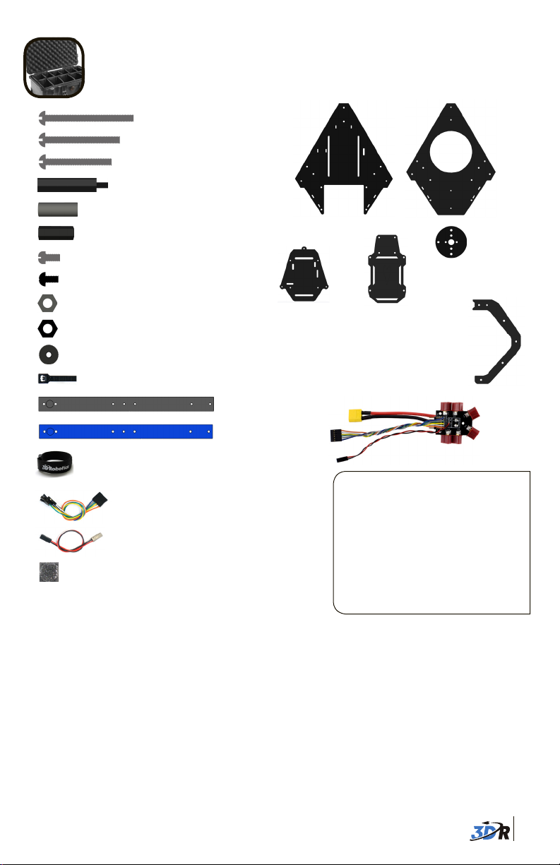
CONTENTS
35 mm steel bolts (3)
30 mm steel bolts (2)
25 mm steel bolts (20)
30 mm threaded spacers (8)
19 mm hollow spacers (13)
18 mm threaded spacers (12)
Your 3DR Y6 Kit contains:
Top plate
Bottom plate
6 mm steel bolts (12)
5 mm nylon bolts (40)
Metal nuts (23)
Nylon nuts (8)
Thumb nuts (5)
11” zip ties (6)
Battery straps (2)
Six-wire RC receiver cable
Two-wire RC receiver cable
Double-adhesive foam mounting squares (4)
Threadlocking compound
You will also need:
Frame:
Electronics:
» Phillips screwdriver (small)
» 5.5 mm (7/32) wrench
» 2 mm (5/64) hex wrench
» Blue threadlocking compound
» Double-sided foam mounting tape
» Soldering equipment
APM plate
Black arm (1)
Blue arm (2)
Co-axial motor
mounting plates (6)
Accessory
plate
C-type landing gear
plates (6)
Power distribution board
These instructions require some minor
soldering. If you’re unfamiliar with
soldering, our friends at Sparkfun have
some great tutorials that can get you
started, including this comic:
learn.sparkfun.com/curriculum/42.
For an example of exactly what you’ll
be doing for this assembly (soldering
Deans connectors to ESCs), check out
this video: youtu.be/3LJIQeKuLLU.
These instructions show the complete assembly and wiring process for a 3DR Y6 using
3DR electronics. For assembling your Y6 Frame Kit using other electronic components,
please adjust these instructions accordingly.
1
Page 3
You may have opted to also receive:
3DR APM 2.6:
3DR APM 2.6
Telemetry adapter
cable
4 mm JP1
jumper connector
6 mm PPM
jumper connector
Micro USB cable
3DR Radio:
Radios (2)
Antennas (2)
Micro-USB cable
Android OTG cable
Autopilot connectors
3DR uBlox GPS+Compass:
6-position to
5-position GPS
cable
3DR uBlox GPS
board with compass
4-position compass
cable
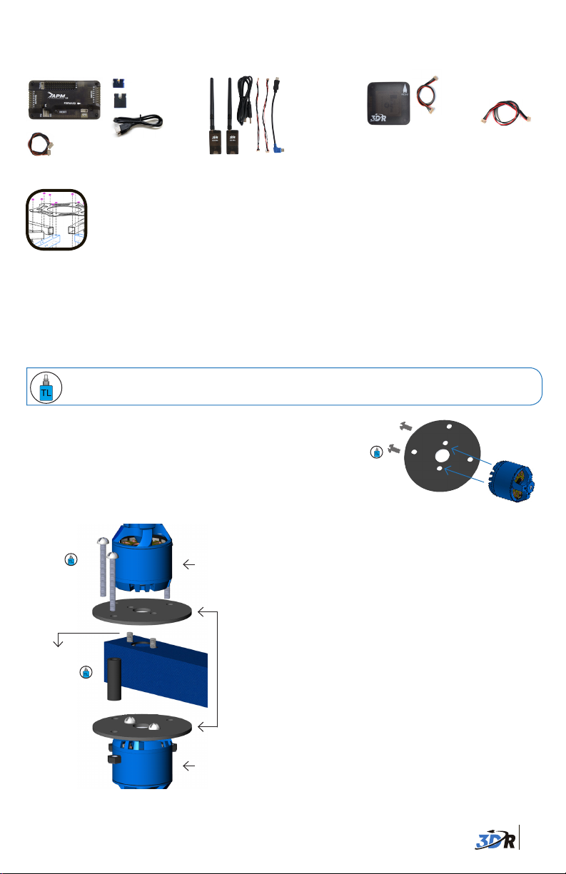
FRAME ASSEMBLY
1 Attach motors to arms
Each arm of your Y6 will have a top motor and a bottom motor attached to the arm using
co-axial motor mounting plates. To ensure motors are securely bolted to arms, apply a small
amount of threadlock to each bolt before fastening.
Threadlocking compound is an important component to ensure your motors remain
firmly attached! For application tips, check out this video: goo.gl/bM3MA.
Attach mounting plates to bottom motors:
Using two 6 mm steel bolts and one co-axial motor
mounting plate, fasten motor onto plate as shown.
Repeat for three of six motors.
Secure with
6 mm bolts
Attach
motor
here
25 mm
bolts
6 mm bolts
19 mm hollow
spacers
Top and bottom motors attached to
arm with mounting plates
Top motor
Mounting
plates
Bottom
motor
Bottom motor assembly
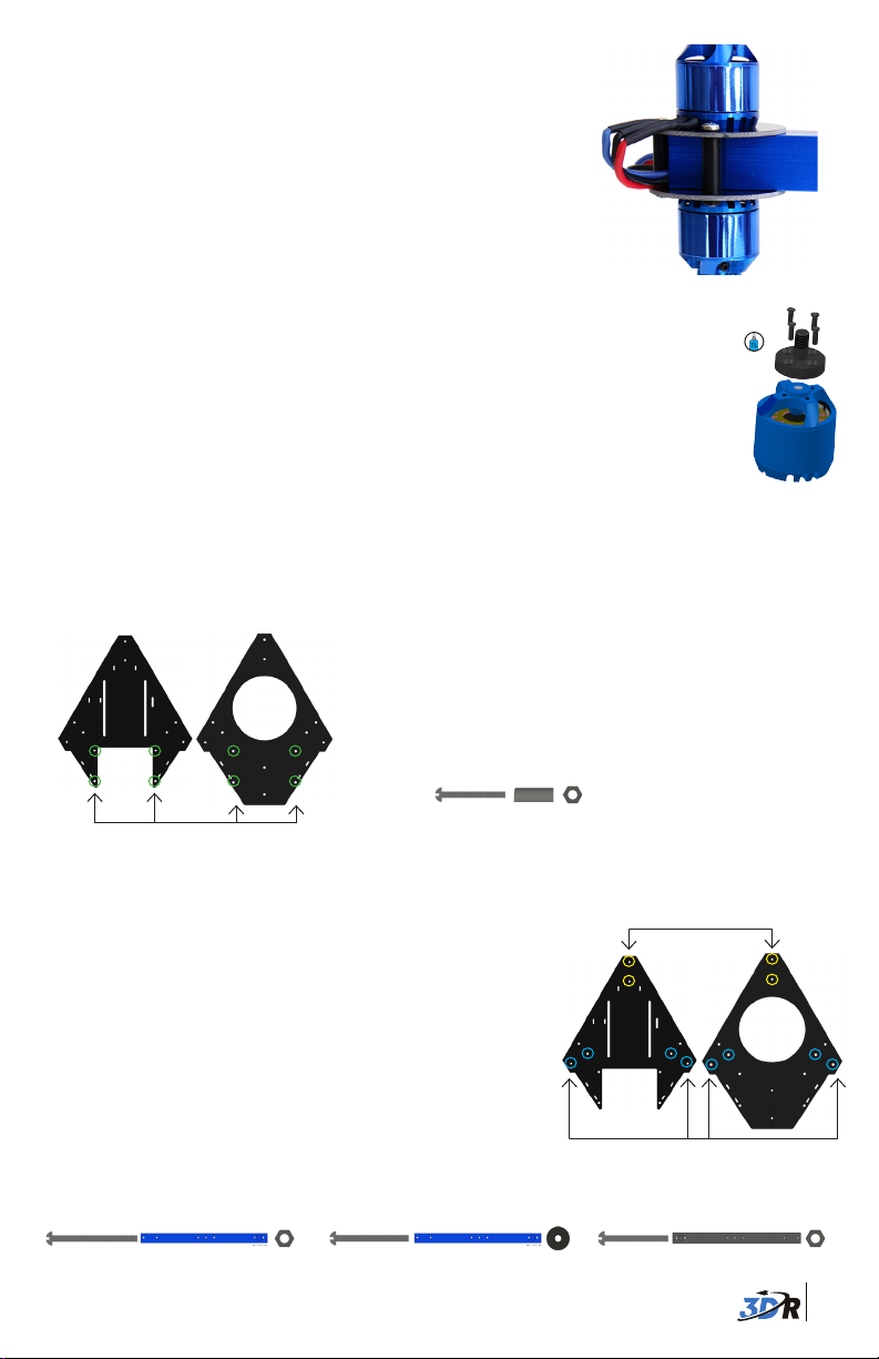
Attach top motors to arms:
Insert mounting plate between top motor and
arm. Make sure motor cables protrude in the
direction of the end of the arm.
Fasten motor and plate to arm using two 6 mm
steel bolts by accessing through the two large
holes in the bottom of the arm. Repeat for all
three arms.
Secure mounting plates together:
Place mounting plates with bottom motors
attached on underside of arm so that the three
outer holes in the plates align. Insert a 19 mm
hollow spacer between top and bottom holes;
thread a 25 mm bolt through spacer and plates.
Secure with a metal nut. Repeat for all three
holes on mounting plates. Repeat for all three
arms.
2
Page 4
Thread motor cables through arms:
Thread the cables from the top motors through
the ends of the arms. You’ll want to distinguish
between top and bottom motor cables, so use a
pen or piece of tape to mark the protruding ends of
the top motor cables before threading the bottom
motor cables through the arms.
Completed motor assembly
Install motor collets2
Attach a threaded collet to the top of each motor using the
four small screws included with collets. Apply threadlock to
each screw before fastening. Repeat for all six motors.
Motor collet assembly
3 Attach top and bottom plates to arms
The top and bottom plates will form the main frame of your copter. We’ll attach these plates
both to each other and to your copter’s arms.
Top plateBottom plate
Attach top and bottom plates together through the
four aligning holes near the front ends of the plates as
shown using a 25 mm bolt, 19 mm hollow spacer, and
metal nut.
25 mm bolt + 19 mm spacer + metal nut
Attach at four points
Next attach the arms to the plates. The black arm will
attach to the narrowest angle of the triangular plates.
The two blue arms indicate your copter’s front-facing
Attach black arm here
direction and will attach to either side of the front of the
plates.
Place the arm between the two plates so the two holes
in the arm align with the holes in the plates. Insert a bolt
into each hole from under the bottom plate and secure
with nuts above the top plate. For inner holes use 35 mm
bolts and metal nuts; for outer holes on blue arms use 30
mm bolts and thumb nuts; for the outer hole on the black
arm use a 25 mm bolt and metal nut. Insert bolts from
below the bottom plate so that nuts are attached above
Attach blue arms here
the top plate.
Inner holes use: Outer hole (black arm) use:
35 mm bolt + arm + metal nut
Outer holes (blue arms) use:
30 mm bolt + arm + thumb nut
25 mm bolt + arm + metal nut
3
Page 5
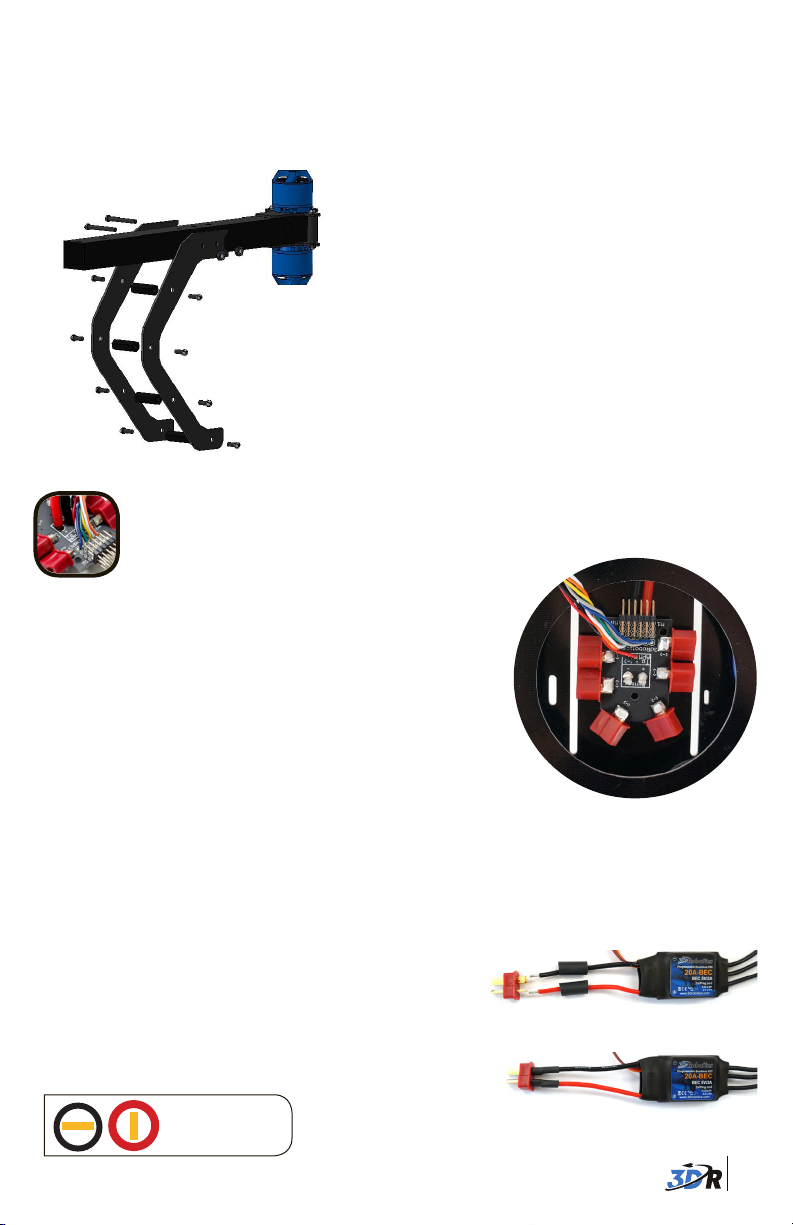
4 Assemble legs
Your Y6 has three legs, each comprised of two C-type landing gear pieces. To assemble each
leg, align the two pieces and attach through four bottom holes using four 18 mm threaded
spacers and eight 5 mm nylon bolts.
25 mm bolts
Leg assembly
Metal nuts
18 mm
spacers
5 mm
nylon
bolts
For each hole, position spacer between holes;
secure from each side with nylon bolts.
Repeat for all three legs.
Attach legs to arms with C-shape facing
toward motors (to provide clearance for
propellers on bottom motors). Align the two
top holes in the leg with the two holes in the
center of the arm. Insert two 25 mm bolts and
secure with metal nuts.
POWER WIRING
Place power distribution board
1
The power distribution board (PDB) allocates power to
your copter’s motors. Place the PDB in the center of
your copter through the hole in the top plate, resting on
top of the bottom plate. You may want to experiment
with the orientation of the board to accommodate all
necessary wiring.
PDB between top and bottom plates
2 Solder Deans connectors to ESCs
Electronic speed controllers (ESCs) regulate how much power is applied to each motor. To
connect the six ESCs to the PDB, you will need to solder the provided Deans connectors to the
ESCs’ black and red wires.
Add a half-inch length of heat shrink tubing onto
each ESC red wire and black wire. Solder the
positive Deans connector plug to the red wire
and the negative Deans connector plug to the
black wire. Shrink tubing over connections.
Deans to ESC:
Negative = Black
+
-
Positive = Red
Add heat shrink and align wires to correct plugs.
Soldered connectors
4
Page 6

3 Connect motors to ESCs
Conect each motor to an ESC using bullet connectors. The order of the bullet connectors
doesn’t matter at this point but will become important later when we set motor directions,
so make sure you can still access these bullet connectors after assembly is complete. Each
ESC should connect to only one motor. Label your ESCs by motor number according to the
diagram below.
Y6 motor order
Starting with the ESC labeled 1 , connect the ESC three-wire cable to the corresponding
position on the PDB pins (M1 - M6 for motors 1 - 6) with orange wire positioned at the top.
Connect ESC Deans connector to any PDB Deans connector. Note that the order of the ESC
Deans connectors does not matter, while the ESC three-wires cables must match the
motor numbers on the PDB pins. Repeat for all motors and ESCs.
Deans
Pins
Motor #
labels
#1
Motor connected to ESC
Don’t secure the ESCs to the frame until you have confirmed that each motor spins
in the direction specified in the diagram above (see motor setup instructions at
copter.ardupilot.com).
ESC connected to PDB
Label ESCs by motor
number; match ESC
motor number to
PDB pin number.
4 Connect power module to PDB
Connect power module 6-position cable to the power module 6-position port. Place power
module in the center of your copter near the PDB. Connect PDB red and black cable (with
XT60 connector) to power module XT60 connectors.
Power module with 6-wire cable
PDB
5
Page 7
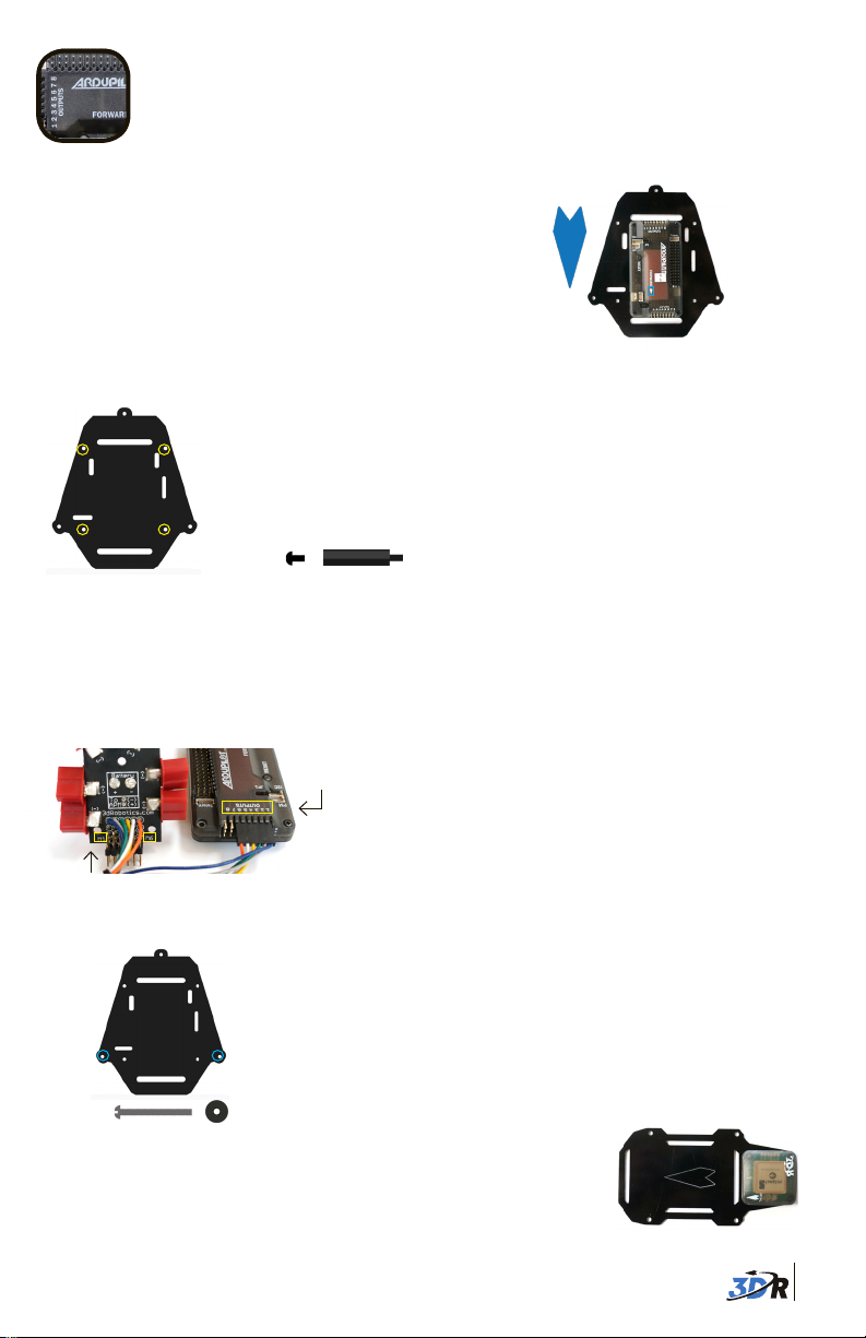
INSTALL APM
1 Mount APM
Place APM 2.6 in the center of the APM plate
with the arrow on the case facing forward
(toward wide end). Use four adhesive
foam squares to secure the bottom of the
case to the plate (one on each corner).
Ensure APM and foam squares are firmly
attached so the position of APM does not shift during flight.
For APM 2.5: Mount APM to the top of the accessory plate.
Using the four holes shown across, insert a 30 mm
threaded spacer over each hole and secure from
below with a 5 mm nylon bolt.
Ensure arrow
on APM points
forward!
3DR APM 2.6
APM plate
APM plate
5 mm nylon bolt + 30 mm spacer
2 Connect APM to power module and PDB
Locate the PDB six-wire cable (multicolored) and the power module six-position cable (red
and black); thread these cables up through the slots in the APM plate where they can connect
to APM.
Connect the power module six-position cable
(red and black) to APM’s PM port. Connect the
PDB six-wire cable (multicolored) to the APM
output signal pins (top row). Ensure that the
individual PDB wires are connected to the
corresponding APM output signal pins. For
example, the wire originating in the position
marked M1 (motor 1) on the PDB must connect
to APM output signal pin 1.
Accessory plate
PDB wire
positions
APM plate
35 mm bolt + thumb nut
3
Mount GPS
APM output
pin positions
PDB to APM wiring
The APM plate connects to the ends of the three 35 mm bolts
securing the inside holes of the arms. Place the three outer holes in
the APM plate over the exposed 35 mm bolts on the top plate and
secure with thumb nuts.
Place the GPS module onto the square end of the accessory
plate with the arrow pointing towards the center of the plate. Use
double-sided foam tape to secure case to plate.
Ensure arrow on
GPS points forward!
6
Page 8
For GPS without compass: Attach GPS board to four holes
as shown using four 5 mm nylon bolts, four 30 mm
spacers, and four nylon nuts.
GPS without compass: 5 mm nylon bolt + 30 mm spacer + GPS + nylon nut
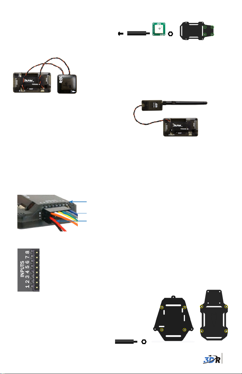
4 Wire additional components to APM
3DR uBlox GPS with Compass:
Connect the 6-position to 5-position cable to the GPS
6-position port and to the 5-position APM GPS port (use
top-entry port not side-entry port). Connect the 4-position
cable to the GPS 4-position MAG port and to the APM I2C port.
3DR Radio air module:
Attach antenna to 3DR Radio air module.
Connect telemetry cable to the air module pins
(ensuring that the red wire aligns with the pin
marked 5V) and to the APM Telem port.
Radio control (RC) receiver:
To connect an RC receiver to APM, use the six-wire and two-wire cables provided with
your copter.
Note: APM also supports one-wire PPM connection with supported receivers.
See copter.ardupilot.com for instructions.
Use the six-wire cable to connect the receiver’s signal pins to APM’s input signal pins.
Use the two-wire cable to connect power and ground pins between APM and the receiver.
APM input pin numbers
Connect six-wire cable to signal pins (top row, “S”).
Connect red wire to power pin (center row, “+”) and
APM inputs wiring
APM Input Signal Pins
6 AUX 2 (OPTIONAL)
5 AUX 1 (MODE SWITCH)
4 YAW / RUDDER
3 THROTTLE
2 PITCH / ELEVATOR
1 ROLL / AILERON
black wire to ground pin (bottom row, “-”).
Match the correct control channel
with its corresponding APM input
signal pin.
5 Attach accessory plate to APM plate
Place accessory plate onto the four 30 mm spacers
protruding from the APM plate, and secure with four
nylon nuts.
30 mm spacer + nylon nut
APM plate
Accessory plate
7
Page 9

Now that your Y6 assembly is complete, the following
steps will get you started configuring your copter.
INSTALL SOFTWARE
Mission Planner is free, open-source software providing multiplatform configuration and fullfeatured waypoint mission scripting for autonomous vehicles.
To install Mission Planner on your ground station computer (Windows only), visit ardupilot.
com/downloads, select Mission Planner, and select sort by date (short link: goo.gl/Si5grC).
Select the MissionPlanner - MSI (Microsoft installer package). For the same features as
Mission Planner for Mac, download APM Planner from ardupilot.com.
Mission Planner Downloads Screen
Mission Planner « Downloads
Sort by: Title | Hits | Date
■ MissionPlanner - MSI - 1.2.62
After selecting the most recent MSI, read the
safety information and select Download:
Open the downloaded file to run the Mission Planner Setup Wizard. Select the option to
proceed if prompted with a security warning.
Device Driver Installation Wizard Mission Planner Setup Wizard
Mission Planner Setup Wizard will
automatically install the correct device
drivers.
Mission Planner will notify you when an update is available;
please always run the most current version of Mission Planner.
Launch Mission Planner to explore
the capabilities of your autonomous
vehicle!
Select MSI to download
most recent version.
Download
Mission Planner: Update Message
8
Page 10

Mission Planner: Flight Data Screen
Before flying, complete Mission
Planner’s configuration utilities,
including RC (shown below),
compass, accelerometer, frame
type, and flight mode calibrations.
Visit planner.ardupilot.com for
complete Mission Planner
instructions.
CALIBRATION
Mission Planner’s mandatory hardware calibration steps allow you to
program and configure the APM autopilot for your copter.
Connect APM to your computer using the provided micro-USB cable.
Windows will automatically install the correct drivers for APM.
Select Initial Setup, Install Firmware, and Quad to install flight code firmware onto APM.
APM USB port
Now you can connect APM to Mission Planner.
1
2
3
On the left side of the Initial Setup screen, select Mandatory Hardware. You will need to
perform each of the calibration procedures listed under this menu.
Frame Type: Select your configuration: Plus or X (cross).
Compass: Select the options to enable the compass, to allow automatic declination, and
to select your autopilot type. Select Live Calibration to launch the wizard, and follow the
prompts.
Accel Calibration: Check the box for AC 3.0+, select Calibrate, and follow the prompts to
calibrate the autopilot’s accelerometer. Make sure to wait a couple of seconds before and
after changing the positions of the copter.
Connect APM to Mission Planner:
1 Select Arduino Mega.
2 Select 115200.
3 Select Connect.
9
Page 11
!
CW
CCW
CW
Radio Calibration: Turn on your RC transmitter, select Calibrate Radio, and move all sticks and
switches to their extreme positions. Select Click when Done once the red bars are set for all
available channels.
Show me! Watch videos demonstrating live calibration techniques at 3DRobotics.com/learn.
Complete all configuration procedures as described at copter.ardupilot.com
before attempting your first flight.
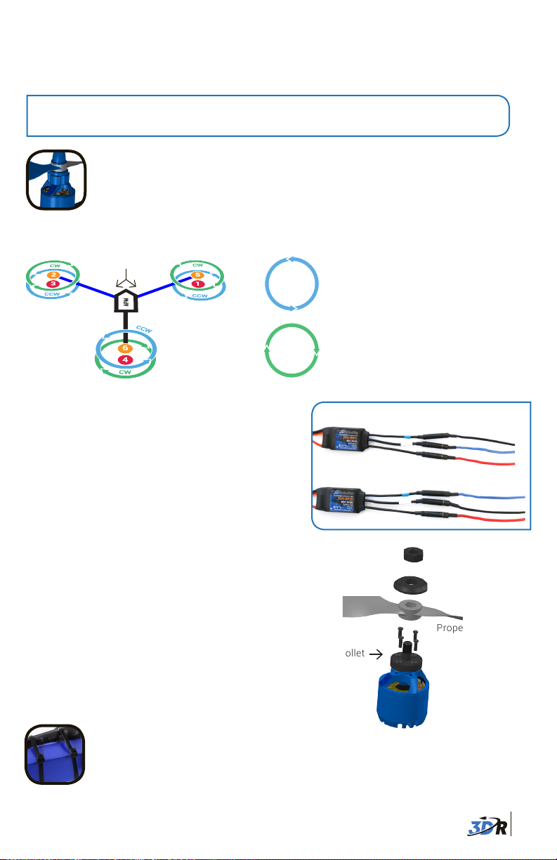
MOTORS & PROPELLERS
The diagram below shows the correct rotation direction for each motor. Before attaching propellers, test the motors to ensure the motor rotation is correct.
Blue arms
Y6 motor order
The rotation direction for each motor is determined
by the connections between the motor and the ESC.
To reverse the rotation direction for a motor, switch
two of the three wires connecting the motor and
the ESC.
Your copter includes normal propellers (unmarked
or marked “SF”) and pusher propellers (marked
“SFP” or “P“). Add pusher propellers to motors
marked clockwise, add normal propellers to motors
marked counterclockwise. Use 10-inch props for
top motors and 11-inch props for bottom motors.
CCW
COUNTERCLOCKWISE ROTATION:
!
USE NORMAL PROPELLER
CW
CLOCKWISE ROTATION:
!
USE PUSHER PROPELLER
1. Connection between motor and ESC
2. Switch two wires to reverse motor rotation.
Prop nut
Remove plastic rings from propeller package, select
the one with the larger internal diameter, and insert it
into the back of the propeller hub.
Add propeller to motor collet with writing
facing up in relation to the sky. This means
you’ll need to attach props to bottom motors
upside down! Add the washer and prop nut above
the propeller; tightly fasten prop nut to threaded collet.
Safety Check! Ensure writing on props faces up.
SECURE WIRING
Before flying, use zip ties to secure ESCs to the frame.
Washer
Propeller
Collet
Motor
10
Page 12

Ensure that all wires are secured so they
will not become entangled in spinning
propellers, are not too tight around corners
(no hard 90-180 degree bends), and do not
pull on the APM or other components.
ESCs and wiring secured with zip ties
FOLDING
Your Y6 can fold for ease of transport. To collapse the blue arms, remove thumb nuts and bolts
from outer holes, and slide blue arms toward black arm.
Remove thumb nuts and
bolts from outer holes.
Travel positionFlight position
To collapse the legs, remove the bolts and nuts from the inner holes where the legs attach to
the arms.
Remove nut and bolt
from inner hole.
Travel positionFlight position
Fold.
Fold.
Visit copter.ardupilot.com to learn about multicopter safety, hardware
and software configuration, using autonomous flight modes, tuning,
designing missions with waypoints and events, troubleshooting, and
more. For customer support, contact us at help@3DRobotics.com or
call our support line at +1 (858) 225-1414 M-F 8-5 PST Happy flying!
11
 Loading...