

Page 1

DIY QUAD
Build Manual
V.A
2014
1
Page 2

Contents
Thanks for purchasing a DIY Quad!
These instructions will show you how to assemble a Quad using the Pixhawk
autopilot system and ArduCopter/APM:Copter firmware. If you plan to use
other components in your build, please adjust these instructions accordingly.
For online instructions, visit 3dr.com/diy-quad-kit.
Frame parts 3
Electronics 4
Tools 4
1 Motor assembly 5
2 Power system wiring 8
3 Body plate assembly 10
4 Pixhawk assembly 15
5 Leg assembly 21
6 Calibration 22
7 Propeller assembly 22
2
Page 3
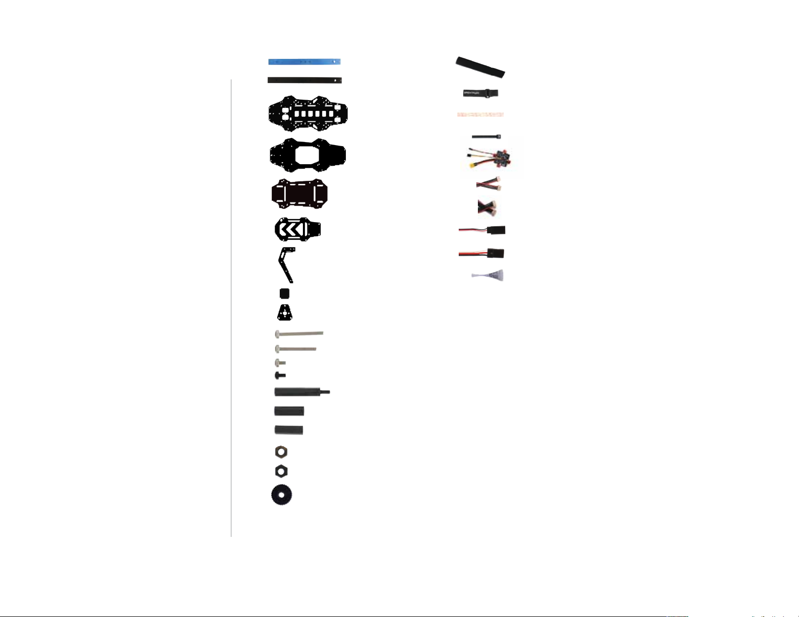
Frame parts
blue arms (2)
black arms (2)
velcro strips (one pair)
velcro straps (3)
base plate
top plate
Pixhawk plate
accessory plate
leg plates (8)
leg support plates (4)
motor plates (8)
30 mm bolts (6)
25 mm bolts (30)
5 mm bolts (32)
nylon bolts (4)
30 mm male-female standos (4)
dual lock
zip ties
power distribution board
15 cm four-wire cable
15 cm six-wire cable
15 cm female-female servo cable
30 cm male-female servo cable
threadlocker
19 mm hollow spacers (20)
18 mm female-female standos (12)
metal nuts (42)
nylon nuts (4)
thumb nuts (2)
3
Page 4
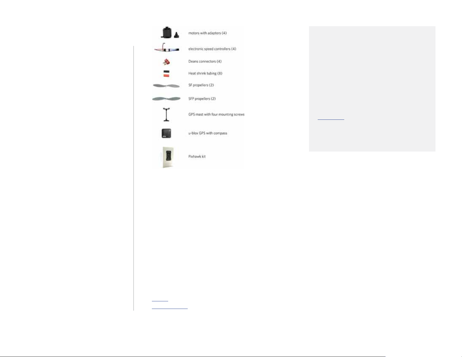
Electronics
This build uses the Pixhawk autopilot
system, including these components:
• Pixhawk autopilot
• u-blox GPS with Compass
• Telemetry radios
• Radio control system
• ArduCopter/APM:Copter firmware
Click here for more information
about these components and to view
compatible radio control systems.
Tools
To complete this build, you will need the following tools not included with your kit:
• Phillips screwdriver
• Double-side foam tape or other mounting adhesive
• Soldering equipment
Note: The electronics for this build require soldering. If you’re unfamiliar with soldering,
our friends at Sparkfun have some great tutorials that can get you started, including this
comic. For an example of exactly what soldering you’ll be doing in this build, view this
video tutorial.
4
Page 5
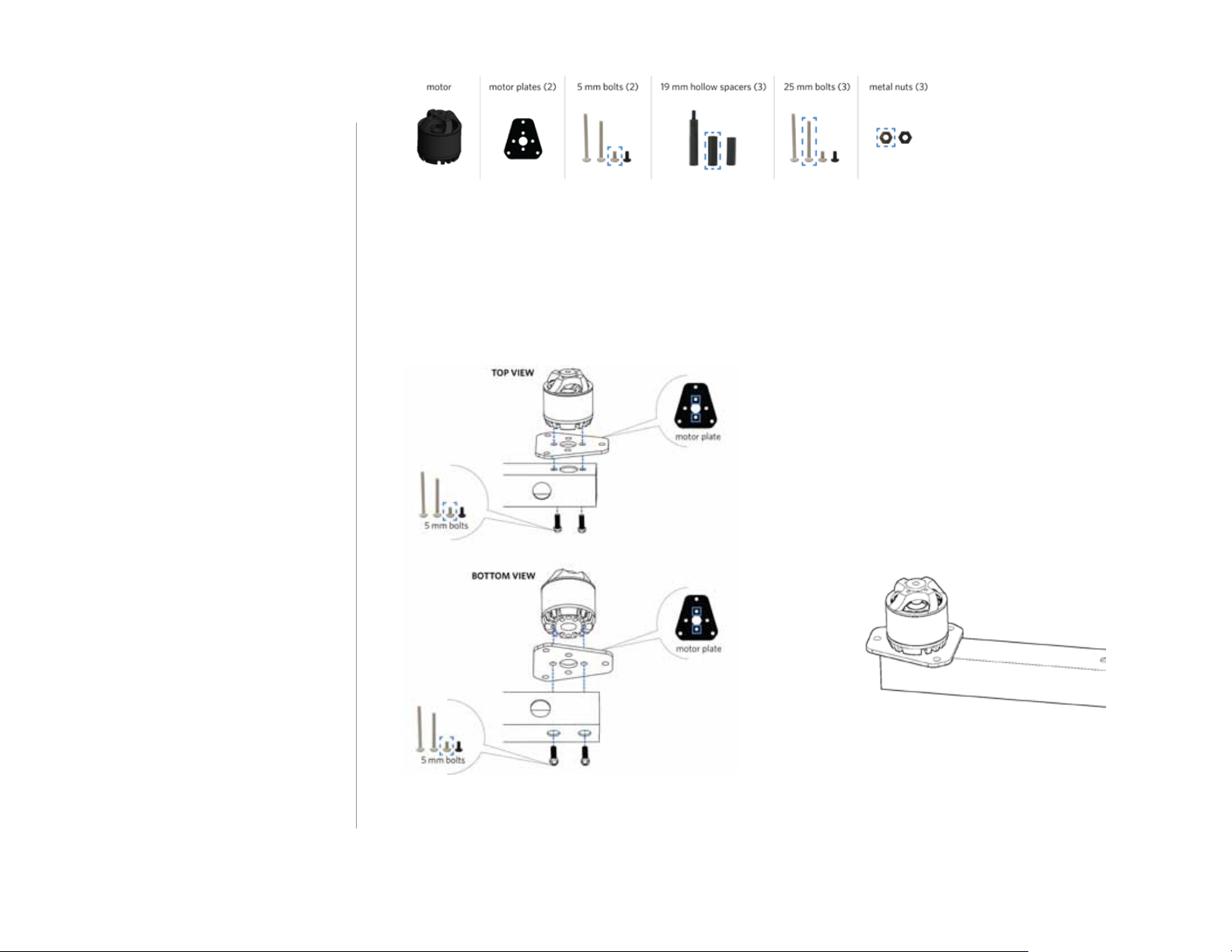
1 Motor
assembly
Follow these instructions to assemble
one motor.
1 Attach motor to arm
Place a motor plate on top of the arm
with the short end of the plate facing
towards the end of the arm. Place the
motor on top of the plate, and align
the two small holes in the motor,
plate, and arm. Orient the motor with
the cables as close as possible to the
hole in the side of the arm.
Apply threadlocker to two 5 mm
bolts, and secure the motor and plate
to the arm from below by accessing
through the two large holes in the
bottom of the arm. When applying
threadlocker, use less than one drop,
and cover only four or five threads
where the bolt connects with the
motor. Make sure to insert the bolts
into the holes in the bottom of the
motor and not into the slots where
they could interfere with the motor.
5
Page 6
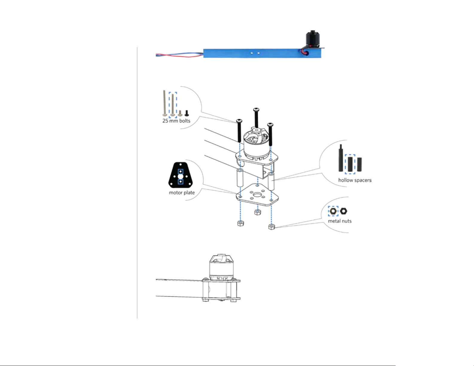
2 Thread motor cables through arm
Thread the motor cables through the
hole in the side of the arm.
3 Attach bottom plate to arm
Place a motor plate against the
bottom of the arm with the short end
of the plate facing towards the end
of the arm. Apply threadlocker to the
ends of three 25 mm bolts (less than
one drop covering four or five threads
at the end of the bolt). Place a 19 mm
hollow spacer between each of the
pairs of holes in the two motor plates.
Place the bolt through the motor
plates and spacer, and secure from
below with a metal nut.
Repeat these instructions for all
motors.
6
Page 7
2 Power system
wiring
Follow these instructions to connect
the power system.
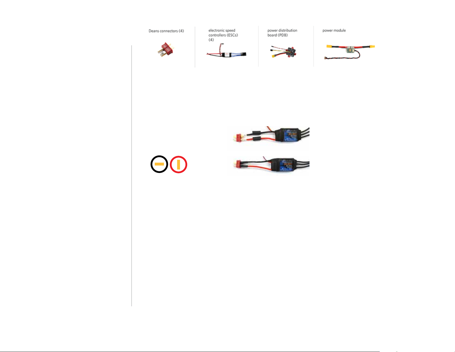
1 Solder Deans to ESCs
Solder a Deans connector to the red
and black wires on each electronic
speed controller (ESC). Check the
Deans connectors for the + and –
markings, and solder the + side to
the red wire and the – side to the
black wire. Don’t forget to add heat
shrink tubing to the wires before
soldering, and shrink the tubing over
the finished connections.
2 Number ESCs
Use tape (or other method) to label
each ESC with a number one through
four.
Deans to ESC:
negative = black
positive = red
-
+
7
Page 8

3 Connect ESCs to PDB
Connect the Deans connectors
(red) on the ESCs to the Deans
connectors on the power distribution
board (PDB) in any order.
Take a look at the PDB and find the
pins labelled M1 through M4
(motors 1 through 4), and make a
note of which color wire connects to
each. Now connect the three-wire
cables from each ESC to these pins
on the PDB according to the ESC
numbers. This is where the order is
critical. Connect the ESC that you
labelled as “1” to the pins on the PDB
labelled “M1”, ESC 2 to PDB pins M2,
ESC 3 to PDB pins M3, and ESC 4 to
PDB pins M4. Connect the white wire
to the signal pin (labelled “M1”), the
red wire to the power pin (labelled
“+”), and the black wire to the ground
pin (labelled “-”).
4 Connect PDB to power module
Attach the XT60 connector (yellow)
on the PDB to the XT60 connector on
the power module.
8
Page 9

3 Body plate
assembly
Follow these instructions to assemble
the body plates.
1 Add velcro straps to base plate
Thread the two velcro straps through
the slots in the base plate. These
straps will hold the battery to the
bottom of your copter. The perfectly
flat side of the plate (without the
protruding nuts) should face down.
Your kit includes two velcro strips to
attach to the battery and the bottom
of the copter. To install, attach the
strip with loops (fuzzy) to the bottom
of the plate between the straps, and
attach the strip with hooks (smooth)
to your battery.
Visit the APM:Copter Wiki and learn
more about which batteries to use
with your copter.
2 Attach arms to base plate
Now we’ll attach the four arms with
assembled motors to the base plate.
Using the innermost hole in the arm
and the hole in the base plate marked
below, insert a 30 mm screw from
the bottom, up through the plate and
the arm. Attach the two black arms
and two blue arms as shown in
relation to the shape of the plate.
(Attach the black arms to the more
elongated end of the plate.)
9
Page 10

It may be helpful to secure each arm
in place temporarily with a metal nut.
3 Label motors
Use tape (or other method) to label
the motors by the numbers shown
here.
4 Connect ESC and motor cables
Connect the motor cables to the
corresponding ESC cables according
to the labelled numbers (connect
motor 1 to ESC 1, motor 2 to ESC 2,
etc). The order of the three cables
determines which direction the
motors will spin and is critical for the
copter to fly correctly. The diagram
above shows which motors need to
spin clockwise (CW) and counterclockwise (CCW).
top = blue
center = black
bottom = red
COUNTERCLOCKWISE (CCW) ROTATION WIRING
top = blue
center = red
bottom = black
CLOCKWISE (CW) ROTATION WIRING
The images below show the correct wiring to produce each direction of rotation. The motor
cables are dierentiated by color. To dierentiate the ESC cables, orient the ESC with the
label facing up, and use the relation of the cables to the label.
10
Page 11

5 Assemble electronics onto base
plate
The base plate holds the power
system: power distribution board
(PDB), power module, and four
electronic speed controllers (ESCs).
Place the assembled power system
onto the base plate. Attach the four
ESCs to the base plate using zip ties.
Orient the ESCs with the labels
down into the holes in the plate.
Alternatively, you can mount the
ESCs to the front of the copter,
perpendicular to the plates, by
securing the zip ties to the small slots
along the front edge of the plates. In
this case, orient the ESCs with the
labels facing out. Ensure that the
power module XT60 connector
protrudes from the back end of the
copter (behind one of the black
arms) where it can easily connect to
the battery.
6 Assemble top plate
Remove any nuts that you may
have used to secure the arms
temporarily to the base plate, and
add the top plate directly on top of
the arms. Secure the four existing
screws with metal nuts, and add a
nylon nut on top of each metal nut.
TOP VIEW
3
3
2
3
1
3
2
1
2
1
3
3
1
3
2
3
11
Page 12

Secure the arms to the plates through
the holes in the end of the arms and
the holes in the plates shown below.
Use 30 mm bolts and thumb nuts to
attach the black arms, and use 25
mm bolts and metal nuts to attach
the blue arms. Finally, attach the base
and top plates together with 25 mm
bolts, 19 mm hollow spacers, and
metal nuts where marked below.
BOTTOM VIEW
12
Page 13

7 Thread cables through top plate
Locate the following three cables, and
thread them up through the central
space in the top plate: PDB two-wire
cable (red and black), PDB four-wire
cable (multicolor), and power module
six-wire cable (red and black). These
cables will connect to Pixhawk.
13
Page 14

4 Pixhawk
assembly
Follow these instructions to assemble
the Pixhawk and accessory plates.
1 Mount Pixhawk
Separate the four foam pieces
provided with the Pixhawk kit, and
attach them to the bottom four
corners of the board. Mount Pixhawk
to the Pixhawk plate with the arrow
facing as shown below (towards the
less elongated end of the plate).
2 Mount buzzer and switch
The switch (button) snaps into the
round hole in the accessory plate.
Thread the switch cable through the
hole in the accessory plate from the
top, and gently pull the switch into
place. Using double-sided foam tape,
mount the buzzer to the underside of
the accessory plate.
BOTTOM VIEW
14
Page 15

3 Mount GPS
Place the base of the GPS mast over
the four holes in the accessory plate
with the shorter side of the top of the
mast facing the left side of the plate
(the arrow-shaped holes in the plate
face forward). Add a mounting screw
to each hole, and secure with nuts.
Remove the adhesive backing from
the mast and place the GPS module
onto the mast with the connectors
facing the shorter side and the
arrow on the GPS pointing in the
same direction as the arrow-shaped
holes in the plate.
4 Insert SD card
Insert the micro-SD card into the
slot at the end of Pixhawk. The
APM:Copter sticker can be attached
to the front of Pixhawk.
15
Page 16

5 Connect modules to Pixhawk
Connect the buzzer, switch, splitter,
GPS, power, and telemetry modules
to Pixhawk.
To ensure the most secure cable
assembly, thread the cables through
the holes in the plates where
possible. Where the cables dangle
away from the frame, such as along
the mast, use zip ties to secure the
cables to the frame.
Note: Pixhawk’s DF13 connectors
can be fragile when disconnected
and reconnected multiple times. Do
not pull on the cables to disconnect,
use a fingernail or small, flat tool to
loosen the edges of the connector
until it pops out.
1
5
4
Buzzer and switch: Connect the buzzer to Pixhawk’s BUZZER port, and connect the switch (safety
1
button) to the SWITCH port. These components are mandatory for Pixhawk.
3
2
I2C splitter: Connect the four-wire cable to one of the ports on the splitter and to Pixhawk’s I2C port.
2
GPS with compass: Use the long cables provided with the GPS mast to connect the GPS with
3
compass module to Pixhawk. Connect the four-wire cable to the GPS’ MAG port and to one of the
ports on the I2C splitter. Connect the six-wire cable to the GPS port on the GPS module and to
Pixhawk’s GPS port.
Power module: Connect the six-wire cable (red and black cable protruding from the central space in
4
the top plate of the copter) to Pixhawk’s POWER port.
Telemetry radio: Connect the six-wire cable to a telemetry radio module and Pixhawk’s TELEM 1 port.
5
16
Page 17

6 Connect RC receiver
7 Connect motor outputs
Pixhawk is compatible with PPM RC receivers or PWM receivers with an additional PPM encoder
module. Connect the three-wire cable (red, black, and white) from your PPM receiver or PPM
encoder to Pixhawk’s RC pins with the white wire connected to the signal (s) pin, the black wire
connected to the ground (-) pin, and the red wire connected to the power (+) pin. Click here for
more information on using a PPM encoder or Spektrum Satellite receiver.
Locate the four-wire cable (multicolor) protruding from the
central space in the top plate. Connect it to the main output
signal (s) pins on Pixhawk according to motor number. Recall
your notes from the power system wiring and see which color
wire corresponds to motor 1. Ensure that that color wire is
connected to the main output 1 signal (s) pin. Do not rely on
the colors of the wires shown here, the accuracy of this
component is critical.
Connect backup power (optional)
Connect the two-wire cable (red and black) protruding from the top plate to provide a backup
power source for Pixhawk. Connect the black wire to any of Pixhawk’s main output ground
(-) pins and the red wire to any of the main output power pins (+). This configuration is best
supplemented with a zener diode (visit the APM:Copter Wiki to learn more), but the backup
power method can be used without implementing the additional diode. If you do not wish to
connect backup power, leave the cable disconnected.
17
Page 18

8 Assemble plates
Add a 5 mm nylon bolt to the four
holes in the accessory plate marked
below, and attach a 30 mm stando
to each one below the plate. Add
the Pixhawk plate to the ends of the
standos and secure with metal nuts.
Pixhawk plate
nylon bolts
accessory plate
30 mm spacers
metal nuts
18
Page 19

Place the assembled plates over the
exposed bolts in the top plate, with
the arrows facing towards the blue
arms, and secure with metal nuts.
metal nuts
Pixhawk plate
9 Mount remaining components
Select a location on the copter to
mount the I2C splitter, telemetry
radio, and RC receiver. Use dual lock
or double-sided foam tape to mount
the components. Check that all
components are connected securely
to Pixhawk.
Where you place the components on
the copter is ultimately limited by
the length of the cables between
modules. Experiment with the
dierent length cables provided with
your kit, and find the best place for
each module on your copter.
top plate
(mast not pictured)
19
Page 20

5 Leg assembly
Follow these instructions to assemble
one leg.
5 mm bolts (6)leg plates (2) leg support plate
18 mm female-to-female
threaded standos (3)
25 mm bolts (2)
metal nuts (2)
1 Assemble leg
Align the leg plates, and place a
stando between each of the bottom
three pairs of holes in the plates.
Secure each stando to the plates
with a 5 mm bolt on each end. Insert
the support plate into the horizontal
slots at the top of the leg.
2 Attach leg to arm
Align the two holes in the top of the
leg with the two holes in the center of
the arm. Orient the leg with the point
facing towards the center of the
copter. Insert two 25 mm bolts
through the arm and the leg, and
secure with metal nuts.
leg support plate
18 mm spacers
5 mm bolts
5 mm bolts
metal nuts
25 mm bolts
Repeat these steps for each leg of
your copter.
20
Page 21

6 Calibration
Your Y6 assembly is almost
complete. Now it’s time to go
online, download software, and begin
calibrating Pixhawk to work with your
new frame. Do not proceed to
propeller assembly with performing
calibration.
7 Propeller
assembly
View the calibration instructions online at
3dr.com/diy-y6-kit.
Follow these instructions to assemble
propellers.
1 Assemble propellers
Remove the rings from the
propeller package. Select the ring
with the smaller internal diameter,
and insert it into the back of the
propeller hub.
21
Page 22

2 Assemble propeller adapters
Select the propeller adapters and
the longer screws provided with the
adapters. Do not use the x-shaped
plate. Apply threadlocker to the three
small screws included with the
propeller adapters (less than one
drop covering four to five threads).
Attach an adapter to the top of each
motor.
3 Add propellers
Your Quad uses SF and SFP
propellers. These propellers are
labelled on the package and on the
propeller itself. Add SF and SFP
propellers to the arms shown in the
diagram below with the writing on
the propeller facing towards the sky.
The right propeller order and
orientation is critical for your
copter to fly correctly. Add the
washer above the propeller, and
secure the nut tightly on top.
Ensure that the writing on the propellers faces the
sky.
22
Page 23

Your Quad build is now complete! Before your first flight,
please read all safety information
and first flight instructions at
copter.ardupilot.com/wiki/tableof-contents/.
COMPLETE QUAD
For customer support, contact us
at help@3dr.com or call our
support line at +1 (858) 225-1414
Monday through Friday, from 8
am to 5 pm, PST.
23
 Loading...