

Page 1

3Com 10/100 LAN+56K
®
Modem CardBus PC Card
User Guide
PDF Version
Prepared August 1998
Page 2

3Com Corporation
5400 Bayfront Plaza
Santa Clara, California
95052-8145
Copyright © 1998, 3Com Corporation. All rights reserved. No part of this documentation may be reproduced
in any form or by any means or used to make any derivative work (such as translation, transformation, or
adaptation) without written permission from 3Com Corporation.
3Com Corporation reserves the right to revise this documentation and to make changes in content from time
to time without obligation on the part of 3Com Corporation to provide notification of such revision or change.
3Com Corporation provides this documentation without warranty, term, or condition of any kind, either
implied or expressed, including, but not limited to, the implied warranties, terms or conditions of
merchantability, satisfactory quality, and fitness for a particular purpose. 3Com may make improvements or
changes in the product(s) and/or the program(s) described in this documentation at any time.
If there is any software on removable media described in this documentation, it is furnished under a license
agreement included with the product as a separate document, in the hard copy documentation, or on the
removable media in a directory file named LICENSE.TXT or !LICENSE.TXT. If you are unable to locate a copy,
please contact 3Com and a copy will be provided to you.
UNITED STATES GOVERNMENT LEGEND
If you are a United States government agency, then this documentation and the software described herein
are provided to you subject to the following:
All technical data and computer software are commercial in nature and developed solely at private expense.
Software is delivered as “Commercial Computer Software” as defined in DFARS 252.227-7014 (June 1995)
or as a “commercial item” as defined in FAR 2.101(a) and as such is provided with only such rights as are
provided in 3Com’s standard commercial license for the Software. Technical data is provided with limited
rights only as provided in DFAR 252.227-7015 (Nov 1995) or FAR 52.227-14 (June 1987), whichever is
applicable. Y ou agree not to remove or deface any portion of any legend provided on any licensed program
or documentation contained in, or delivered to you in conjunction with, this User Guide.
Portions of this documentation are reproduced in whole or in part with permission from (as appropriate).
Unless otherwise indicated, 3Com registered trademarks are register ed in the United States and may or may
not be registered in other countries.
3Com and the 3Com logo are registered trademarks of 3Com Corporation.
Microsoft, MS-DOS, Windows, and Windows NT are registered trademarks of Microsoft Corporation. Novell
and NetWare are registered trademarks of Novell, Inc.
All other company and product names may be trademarks of the respective companies with which they are
associated.
Page 3

ONTENTS
C
NSTALLING AND CONNECTING THE CARD
I
1
Identifying the LAN+Modem Card Ports 1
Inserting the LAN+Modem Card 2
Connecting to a Network 3
LAN Connector LEDs 4
Connecting to a Telephone Line 5
Disconnecting the Cables 6
Installing Diagnostics 6
2
3
INDOWS
W
About Windows 95 Prompts 7
Installing the Network Interface 8
Setup Procedure 8
Installing Network Software Components 8
Confirming Installation 10
Installing the Modem Interface 10
Setup Procedure 10
Confirming the Installation 11
Testing the Modem 11
Uninstalling the Card 11
Removing the Card 11
Removing Card Software 11
Troubleshooting 12
Updating Windows 95 Drivers 13
Updating LAN Drivers 13
Updating Modem Drivers 13
INDOWS
W
Installing the Network Interface 15
Setup Procedure 15
Installing Network Software Components 16
Confirming Installation 17
Installing the Modem Interface 17
Setup Procedure 17
Confirming Installation 18
Testing the Modem 18
Uninstalling the Card 19
Removing the Card 19
95
98
Page 4

Removing Card Software 19
Troubleshooting 20
4
W
INDOWS
Installing the Network Interface 21
Installing the Modem Interface 22
Uninstalling the Card 23
Troubleshooting 23
NT
U
5
Hints for Good Connections 25
Software Settings 25
Setup for Communications Applications 25
Making a Call with HyperTerminal 26
Making Calls from a Hotel or Business PBX 26
Additional Modem Features 27
AT Commands 28
S Registers 32
Modem Troubleshooting 52
D
6
LAN Diagnostics 55
Modem Diagnostics 55
SING
Redialing 27
Dialing Stored Numbers 27
Call Progress Detection 27
Fax Support 27
Common Registers 33
Analog Modem Registers 46
IAGNOSTICS
M
THE
Entering AT Commands 28
ODEM
ELL
D
T
ARRANTY
W
ECHNICAL
AND
UPPORT
S
EGULATORY
R
NFORMATION
I
Page 5
I
NSTALLING
AND
C
ONNECTING
THE
1
Identifying the
LAN+Modem Card
Ports
C
ARD
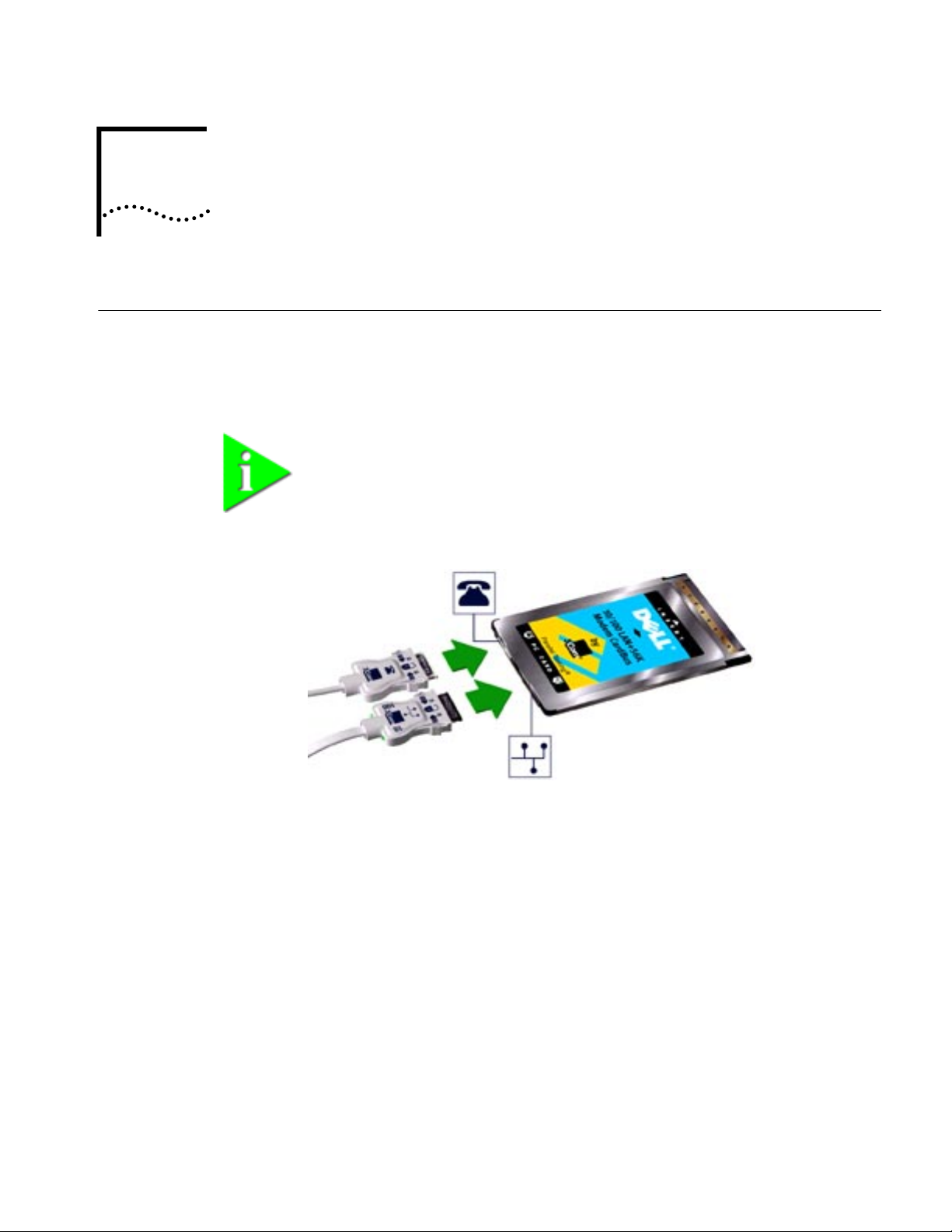
The dual-function LAN+Modem card has a LAN port and modem port. The
connectors and card ports are color coded. Take care to connect each cable to the
correct card port.
NOTE: When attaching connectors to the LAN+Modem card, insert them
with the icon side up. The connector should seat easily without forcing.
Figure 1 LAN and Modem Ports
Page 6
2
C
HAPTER
1: I
NSTALLING
Inserting the
LAN+Modem Card
AND
C
ONNECTING
THE
C
ARD
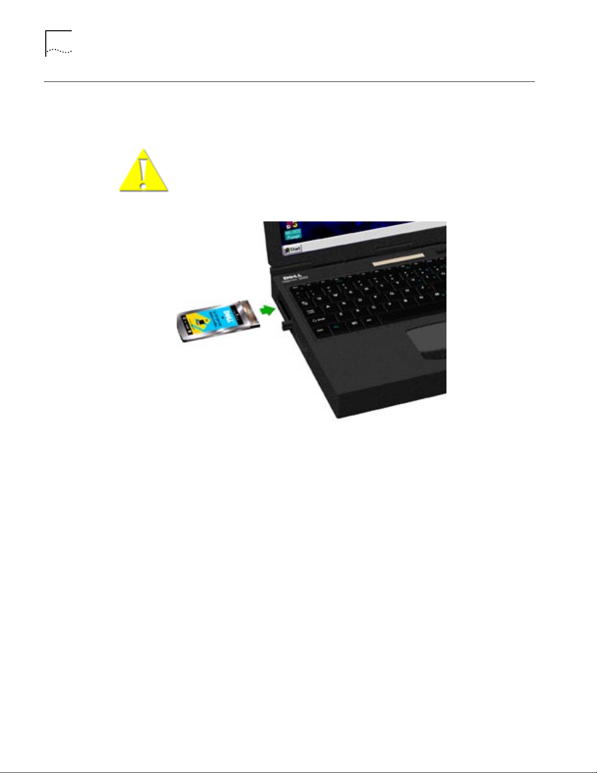
To install the card, slide it into the PC Card slot as shown below. The power to the
computer can be on or off. Without forcing the card, push until it seats firmly.
CAUTION : Forcing the card into the slot may bend the pins. If you do not know
how to insert cards in your computer, refer to the documentation supplied with
your computer on using PC Card (PCMCIA) slots.
Figure 2 Inserting the LAN+Modem Card
Page 7
1
2
Connecting to a Network 3
Connecting to a
Network
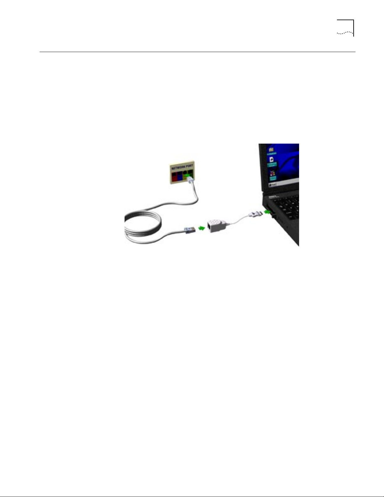
Before connecting the LAN+Modem card to the network, be sure that you have
the cable appropriate for a network connection at your site.
Attach the network connector at the end of the network cable to the LAN port
(See “Identifying the LAN+Modem Card Ports” on page 1) on the LAN+Modem
card.
Connect one end of the RJ-45 extension cable to the network connector and the
other end to the network segment.
Figure 3 Connecting the Twisted-Pair Adapter
Page 8
4
C
HAPTER
1: I
NSTALLING
LAN Connector LEDs
AND
C
ONNECTING
THE
C
ARD
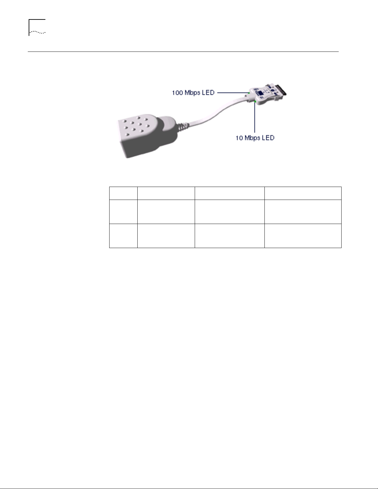
The LEDs on the network connector display the status of your network link.
Figure 4 LEDS
Table 1 LAN Connector LEDs
LED Description Steady Off
10 LNK Link integrity Good 10BASE-T
connection between PC
Card and hub
No connection between card
and hub. (Off when 100 LNK
LED is on.)
100 LNK Link integrity Good 100BASE-TX
connection between PC
Card and hub
No connection between card
and hub. (Off when 10 LNK
LED is on.)
You can use the LEDs to verify link integrity, but the LAN+Modem card must be
connected to the network and the network drivers must be installed. For
information on installing drivers, see:
“Windows 95” on page 7
■
■
“Windows 98” on page 15
■
“Windows NT” on page 21
Page 9
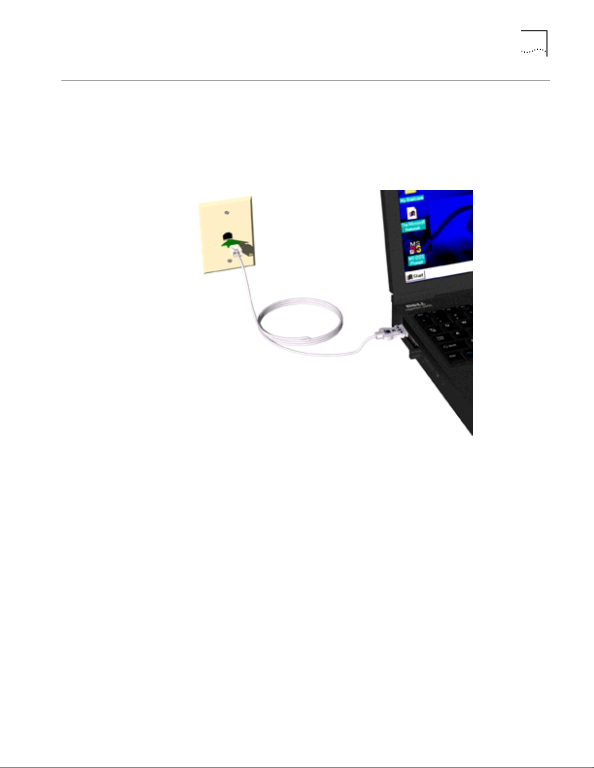
Connecting to a Telephone Line 5
Connecting to a
Telephone Line
To connect the LAN+Modem card to a telephone line, attach the modem adapter
to the modem port (See “Identifying the LAN+Modem Card Ports” on page 1).
The line port on the modem cable connector is labeled with an RJ-11 (modular
telephone plug) icon. Attach the connector with the icon facing up. Next, attach
the RJ-11 adapter at the other end of the modem cable to the telephone wall
plug.
Figure 5 Connecting the Modem Adapter to the Telephone Line
Page 10
6
1
2
C
HAPTER
1: I
NSTALLING
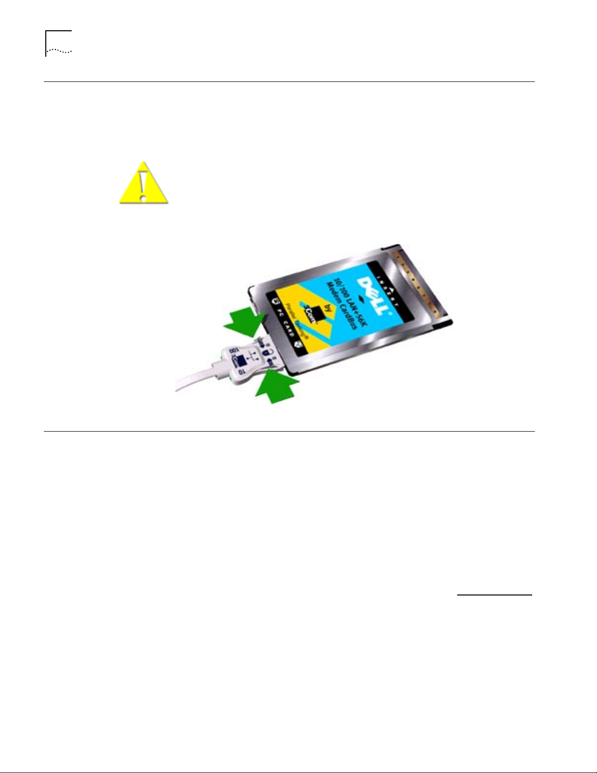
Disconnecting the
Cables
AND
C
ONNECTING
THE
C
ARD
The LAN and modem cables are designed to lock in place when you connect them
to the card. To release the cable from the card, squeeze the release clips located on
the sides of the connector .
CAUTION : Do not pull or attempt to disconnect the cable without squeezing
the release clips. Otherwise, you may damage the card and make it inoperable.
Figure 6 Disconnecting Cables from the Card
Installing Diagnostics
If you did not install the diagnostics utilities when you installed this manual, you
should do so now. In addition to installing the manual, the Setup program installs
LAN Diagnostics, Modem Diagnostics, and a PDF version of this guide.
Insert User Guide and Diagnostics Installation Disk 1 in the floppy drive and click
Start .
Click Run and type a:\setup [Enter] to begin installation. Choose which options to
install and follow the instructions as they appear.
A PDF version of the
LAN+Modem Card User Guide.PDF
User Guide is also provided. The file is called For Print -
and is suitable for viewing or printing with the
Acrobat Reader. If you do not have a copy of the Acrobat Reader, you can obtain
the program at no cost from the Adobe W orld Wide Web site at www
.adobe.com.
For information on running diagnostics, see “Diagnostics” on page 55.
Page 11

2
W
INDOWS
NOTE: If you are reinstalling the card, make sure you have completed the
procedures for
“Uninstalling the Card” on page 11 .
95
About Windows 95
Prompts
During setup, Windows 95 may prompt for an Installation Disk or the Windows
CD several times. Be sure that the path or device you supply to this prompt is
correct. Here are some guidelines:
■
If Windows 95 prompts for a disk from the manufacturer, put the LAN+Modem
card
Windows 95/98 Installation Disk in the floppy drive. On most systems, this
will be drive A, so the path in the dialog box should point to A:\.
If Windows 95 prompts for the Windows CD, put the Windows 95 CD in your
■
CD-ROM drive. Often, this will be drive D. If so, the path in the dialog box
should point to D:\WIN95.
■
Some computers are delivered with Windows 95 installed, but no CD is
supplied. If this is the case with your computer, you must supply the path
where the Windows 95 software resides. Check your owner’s manual for
details. Often, this will be a subdirectory of your Windows folder. A common
path for these driver files is C:\WINDOWS\OPTIONS\CABS, so you would supply
this path in the dialog box.
Page 12

8
1
C
HAPTER
2: W
INDOWS
95
Installing the Network
Interface
Setup Procedure Before installing the network interface, insert the LAN+Modem card and connect
■
Setup Procedure
Installing Network Software Components
■
■
Confirming Installation
to the network as described in “Installing and Connecting the Card” on page 1.
Obtain the following information from your MIS department:
■
For Windows 95 networking, your computer name and workgroup name.
■
For your network account, your user name and password.
To set up the network interface:
T urn on the computer and start Windows 95. Windows 95 detects the card during
startup.
2
Follow the instructions in the
LAN+Modem card
Next
.
Windows 95/98 Installation Disk
Update Device Driver Wizard
in the floppy drive and click
dialog box. Insert the
Installing Network
Software Components
3
After the system finds the installation files on the disk, it displays the card name,
3Com 10-100 LAN + 56K Modem CardBus PC Card (Ethernet interface)
. and
prompts for the location of the driver files.
4
Click
Finish
to copy the files needed for the Ethernet interface.
■
If prompted for the “3Com 10-100 LAN + 56k Modem PC Card Windows
95/98 Installation Disk,” select the floppy drive as the location of the files.
■
If prompted for Windows 95 files, supply your CD or type the path to the
directory where your Windows 95 files reside. Normally, this path is
C:\WINDOWS\OPTIONS\CABS.
OK
Click
5
If Windows 95 opens the Network Setup box, supply your computer name and
workgroup name, then click
6
When Windows 95 prompts whether to reboot the computer, remove the
Windows 95/98 Installation Disk
to finish copying the required files.
Close
.
from the floppy drive and click
YES. Windows 95
will detect and install the modem interface when it reboots.
If you choose not to reboot after installing the network interface, you must install
the modem interface manually when Windows 95 discovers the modem. See
“Installing the Modem Interface” on page 10.
You will need to install four types of network components for Windows 95
networking: Client, Adapter, Protocol, and Service. These components are
installed through the Network application in the Control Panel. Open the Network
application in the Control Panel to see which network components are currently
installed.
Page 13

Installing the Network Interface 9
Before installing network components, consult with your network manager or MIS
representative for the options you require for your network.
1 Open the Network window by double-clicking the Network icon in the Control
Panel.
2 Click Add to add new or additional network components.
Some networks do not require all four components. Table 2 shows which
components are required for four widely used network types.
Table 2 Adding Network Software Components
Type of Network Component Manufacturer Option to Select
Microsoft Networking and Netware Adapter 3Com 3Com 10/100 LAN +
Microsoft Networking (for Windows 95,
Windows NT, and Windows 98)
NetWare for Bindery (for NetWare 3.x and
NetWare 4.x in bindery mode)
NetWare Directory Services (NDS) (for
NetWare 4.x)
Client Microsoft Microsoft Client for
Protocol Microsoft NetBEUI
Service Microsoft File and printer sharing
Client Microsoft Microsoft Client for
Protocol Microsoft IPX/SPX-compatible
Client Microsoft Microsoft Client for
Novell Novell NetWare 32-bit
Protocol Microsoft IPX/SPX-compatible
Novell IPX/SPX Protocol*
Service Microsoft
Novell
56K Modem CardBus PC
Card
Microsoft Networks
for Microsoft Networks
NetWare Networks
Protocol
NetWare Networks*
Client*
Protocol*
Service for NetWare
Directory Services*
TCP/IP
(for UNIX® networking)
* Download software from the indicated manufacturer’s BBS or World Wide Web site.
Client Microsoft Microsoft Client for
Protocol Microsoft TCP/IP
3 Each time you add one of these components, Windows 95 creates a new entry in
the Network window. As these components are added, you may be asked to
provide:
■ NetWare or Microsoft client software on hard disk, floppy disks, or CD
■ Windows 95 system installation files on hard disk, floppy disks, or CD
■ The Windows 95/98 Installation Disk that came with your LAN+Modem
card
Microsoft Networks
Page 14

10 CHAPTER 2: WINDOWS 95
Confirming Installation
4 When all of these components have been added, modify their properties to
comply with the network requirements for your site. The parameters you will need
to add or customize for network operation under Windows 95 can be found
under the Properties tab for the network components you added.
1 Double-click the My Computer icon.
2 Double-click the Control Panel icon.
3 Double-click the System icon. The System Properties box appears, detailing your
system setup.
4 Click the Device Manager tab. A list of devices appears, arranged by type.
5 Double-click Network Adapters. The LAN+Modem card name appears, confi rming
successful installation.
6 Double-click the entry for the LAN+Modem card to display a description of the
card and its current status. The device status should indicate “This device is
working properly.”
7 Click the Cancel button to return to System Properties.
Installing the Modem
Interface
Setup Procedure If you choose not to reboot after installing the network interface, you must install
8 Click OK to exit System Properties.
■ Setup Procedure
■ Confirming the Installation
■ Testing the Modem
the modem interface manually when Windows 95 discovers the modem.
1 Windows 95 displays a New Hardware Found dialog box and identifies the
modem interface.
2 Insert the LAN+Modem card Windows 95/98 Installation Disk in the floppy drive.
3 Select the floppy drive as the location of the modem driver files and click NEXT.
4 When configuration is complete, Windows 95 displays the card name,
3Com 10-100 LAN + 56K Modem PC Card (Modem interface).
5 Click Finish to quit the installation program.
The installation program installs a 3Com Modem Setting application in the Control
Panel. Use Modem Setting to change COM port assignments for the modem. The
default is COM5. Change the COM port to a lower number if you are using older
software that does not recognize COM ports higher than 4.
NOTE: If you remove the LAN+Modem card and reinstall it in another slot, the
first time Windows 95 rediscovers it in the new location it will start another
installation. If the double installation causes problems, uninstall one of the
occurrences of the card. See “Uninstalling the Card” on page 11.
Page 15

Uninstalling the Card 11
Confirming the
Installation
Testing the Modem
To confirm modem installation.
1 Double-click the My Computer icon.
2 Double-click the Control Panel icon.
3 Double-click the System icon. The System Properties box details your system setup.
4 Click the Device Manager tab. A list of devices appears, arranged by type.
5 Double-click Modems. It should display the entry for the 3Com 10-100+56K
CardBus PC Card.
6 Double-click the entry for the LAN+Modem card. It should confirm “This device is
working properly.”
7 Click Cancel, then click OK to exit System Properties.
1 Open the Control Panel and double-click Modems.
2 Select the Diagnostics tab.
3 Click on the COM port assigned to the LAN+Modem card.
4 Click More Info... If the modem is working properly, the test will display a white
box with a list of AT commands. This will confirm that the modem is functioning
properly.
Uninstalling the Card If the card installation is unsuccessful for any reason, your best course may be to
remove the card and its software and repeat the installation procedures with a
fresh installation of the operating system.
Sometimes earlier installations or interrupted installation attempts leave problems
that affect card operation. Possible problems include:
■ One or both of the card functions not working.
■ Windows 95 not detecting the card.
■ The system issuing a warning tone at startup.
If you are having any of these problems, remove the LAN+Modem card and
software using the procedures below, then reinstall the card.
Removing the Card Check your computer manual for information on removing cards. Store the car d in
its original or similar packaging.
CAUTION: Exit any communications or networking applications before
removing the card.
Removing Card
Software
Open Control Panel/System/Device Manager. Select the LAN+Modem card
components and click Remove.
Page 16

12 CHAPTER 2: WINDOWS 95
Using the Device Manager to remove the LAN portion of the card fr om the Device
Manager will uninstall the card, software and documentation.
Be sure to remove both the LAN interface and the modem.
Troubleshooting
Symptom Solution
Basic Troubleshooting, applicable for all
problem situations.
System shows a valid COM-Port setting for
the modem, but your application does not
recognize it.
The LAN device is not functional. LED on the
connector is off or mismatches the real
network speed.
After you remove the card from the system
and then inserted back – Windows runs
installation process again.
Inspect all cables and connections.
Check whether your card if fully inserted into the slot.
Verify whether you have the latest BIOS for your system. If not, check the Web
site for your computer, download the newest BIOS version, and follow the
upgrade instructions.
Check for multiple installations of the card.
Check whether your system’s PC Card CardBus Controller is installed and
running properly: go to Control Panel/System/Device Manager/PCMCIA Card
and verify that the controller is present and shows no errors.
Check the Control Panel/PC Card application to confirm that your card is
recognized by the system.
In the Control Panel/Network application, make sure that you have appropriate
clients and protocols installed.
Use the 3Com Modem Setting application in the control panel to change the
COM port assignment. The default is COM5. Use a lower number if you are
have older software that does not recognize COM ports higher than 4.
Use Control Panel – Device Manager to inspect the status of your LAN card.
If you see a red X, enable the card and set the Properties.
If yo see a yellow exclamation mark, click on the icon to see what the conflict is.
Verify that there are adequate system resources. Try to free system resources
(e.g. disable the infrared port), then remove and reinstall the card.
This is normal behavior for Windows with PCI and CardBus cards installed.
Windows 95 can install one instance of the card for every slot presented in the
system. You will have two instances of the card under the Network and Modem
applications in Control Panel. After the second instance is installed – the hot
swap from one slot to another will be smooth. Be sure to check your settings
under Dial-up Networking and Hyperterminal to ensure that your preferred
settings apply to the correct instance of the card.
The card does not work in your system with
Windows 95 or Windows 95a
Losing network connection after
disconnecting or changing the media speed
when using NetWare servers and IPX/SPX
protocol
After reboot in Dell Latitude CP the card does
not come up.
Earlier versions of Windows (Windows 95 and Windows 95a) are not
supported. Upgrade your system to Windows 95b (OSR2) or Windows 98.
To determine your version of Windows 95, open the Control Panel, select
System, and look at System information under the General tab. If your release is
identified as version 4.00.950 B, you are using OSR2.
This happens when the frame type is selected automatically. A temporary
solution is to reboot after disconnecting and reconnecting the cable in NetWare
networks. The permanent solution is to use specific frame types such as 802.2
or 802.3.
A temporary solution is to remove the card from the slot and then insert it
again. For a permanent solution, use the original Dell Windows 95 installation
CD or obtain QFE 515, 567 and 599 from Microsoft or Dell. Copy these files
into the Windows/System folder.
Page 17

Updating Windows 95 Drivers 13
Updating Windows 95
Drivers
Updating LAN Drivers
Updating Modem
Drivers
Use the following procedure to update the drivers on your system.
1 From the Control Panel, open the System application.
2 Select the Device Manager tab.
3 Double-click Network Adapters.
4 Double-click 3Com 10-100 LAN + 56K Modem CardBus PC Card (Ethernet
interface).
5 Open the Driver tab and click Update Driver.
6 Choose Select Driver from list and click Next.
7 Select Have Disk. Specify the location of the new driver files and click OK.
8 After Windows copies the files, click Restart for the changes to take effect.
1 From the Control Panel, open the System application.
2 Select the Device Manager tab.
3 Double-click Modems.
4 Double-click 3Com 10-100 LAN + 56K Modem CardBus PC Card (Ethernet
interface).
5 Open the Driver tab and click Update Driver.
6 Choose NO: Select Driver from list and click Next.
7 Select Have Disk. Specify the location of the new driver files and click OK.
8 After Windows copies the files, click Restart for the changes to take effect.
Page 18

Page 19

3
WINDOWS 98
NOTE: If you are reinstalling the card, make sure you have completed the
procedures for “Uninstalling the Card” on page 19.
Installing the Network
Interface
Setup Procedure Before installing the network interface, insert the LAN+Modem card and connect
■ Setup Procedure
■ Installing Network Software Components
■ Confirming Installation
to the network as described in “Installing and Connecting the Card” on
page 1.Obtain the following information from your MIS department:
■ For Windows 98 networking, your computer name and workgroup name.
■ For your network account, your user name and password.
To set up the network interface:
1 Turn on the computer and start Windows 98.
Windows 98 automatically detects the LAN function of the card. It displays a New
Hardware Found dialog box and looks for information about the card.
2 When ready to configure the new hardware, Windows 98 opens the Add New
Hardware Wizard. Select Search for the best driver for your device and click Next.
3 Select Floppy Drives, insert the LAN+Modem card Windows 95/98 Installation
Disk, and click Next.
4 After finding the installation files on the diskette, the hardware wizar d displays the
card name, 3Com 10-100 LAN + 56K Modem PC Card (Ethernet interface). Click
Next to copy the required files.
5 Insert the Windows 98 CD if prompted. Optionally, you may specify a location on
the hard disk where the Windows 98 files reside. Typically, this location is
C:\WINDOWS\OPTIONS\CABS. Click OK to copy the files needed for the Ethernet
interface.
There may be a period of inactivity while the system checks your current network
configuration. How much time this takes depends on your settings for network
software components.
6 Click Finish. When Windows 98 prompts whether to r eboot the computer, remove
the Windows 95/98 Installation Disk from the floppy drive and click YES.
Page 20

16 CHAPTER 3: WINDOWS 98
Upon rebooting, Windows 98 automatically detects the modem interface of the
card. See “Installing the Modem Interface” on page 17.
Installing Network
Software Components
You will need to install four types of network components: Client, Adapter,
Protocol, and Service. These components are installed through the Network
application in the Control Panel. The Network window lists which network
components are currently installed.
Before installing network components, consult with your network manager or MIS
representative for the options you require for your network.
1 Open the Network window by double-clicking the Network icon in the Control
Panel.
2 Click Add to add new or additional network components.
Some networks do not require all four components. Table 3 shows which
components are required for four widely used network types.
Table 3 Adding Network Software Components
Type of Network Component Manufacturer Option to Select
Microsoft Networking and Netware Adapter 3Com 3Com 10/100 LAN +
Microsoft Networking (for Windows 95,
Windows NT, and Windows 98)
Client Microsoft Microsoft Client for
56K Modem CardBus PC
Card
Microsoft Networks
Protocol Microsoft NetBEUI
Service Microsoft File and printer sharing
NetWare for Bindery (for NetWare 3.x and
NetWare 4.x in bindery mode)
NetWare Directory Services (NDS) (for
NetWare 4.x)
TCP/IP
(for UNIX® networking)
* Download software from the indicated manufacturer’s BBS or World Wide Web site.
Client Microsoft Microsoft Client for
Protocol Microsoft IPX/SPX-compatible
Client Microsoft Microsoft Client for
Protocol Microsoft IPX/SPX-compatible
Service Microsoft
Client Microsoft Microsoft Client for
Protocol Microsoft TCP/IP
for Microsoft Networks
NetWare Networks
Protocol
NetWare Networks*
Novell Novell NetWare 32-bit
Novell IPX/SPX Protocol*
Novell
Client*
Protocol*
Service for NetWare
Directory Services*
Microsoft Networks
Page 21

Confirming Installation
Installing the Modem Interface 17
3 As these components are added, you may be asked to provide:
■ NetWare or Microsoft client software on hard disk, floppy diskettes, or
CD-ROM
■ Windows 98 system installation files on hard disk, floppy diskettes, or CD-ROM
■ The Windows 95/98 Installation Disk that came with your LAN+Modem card
Each time you add one of these components, Windows 98 creates a new entry in
the Network window.
4 When all of these components have been added, you must modify their properties
to comply with the network requirements for your site. The parameters you will
need to add or customize for network operation under Windows 98 can be found
under the Properties tab for the network components you added.
1 Double-click the My Computer icon.
2 Double-click the Control Panel icon.
3 Double-click the System icon. The System Properties box appears, detailing your
system setup.
Installing the Modem
Interface
Setup Procedure Once the system is rebooted with the LAN+Modem card installed, Windows 98
4 Click the Device Manager tab. A list of devices appears, arranged by type.
5 Double-click Network Adapters. The LAN+Modem card name appears, confi rming
successful installation.
6 Double-click the entry for the LAN+Modem card to display a description of the
card and its current status. The device status should indicate “This device is
working properly.”
7 Click the Cancel button to return to System Properties.
8 Click OK to exit System Properties.
■ Setup Procedure
■ Confirming Installation
■ Testing the Modem
automatically detects the modem interface.
1 Windows 98 opens the Add New Hardware Wizard dialog box and identifies the
modem interface.
2 Select “Search for the best driver for your device” and click Next.
3 Select Floppy Drives, insert the LAN+Modem card Windows 95/98 Installation
Disk, and click NEXT.
4 After the hardware wizard finds the installation fi les on the diskette, it displays the
card name, 3Com 10-100 LAN + 56K Modem PC Card (Modem interface). Click
Next.
5 Click Finish when the system displays “Installation complete.”
Page 22

18 CHAPTER 3: WINDOWS 98
After installation is complete, a 3Com Modem Setting application is installed in
the Control Panel. Open Modem Setting to change the COM port assignment for
the LAN+Modem card. Dell’s default is COM5. Y ou may need to change the COM
port to a lower number if you are using older software that does not recognize
COM ports higher than 4.
NOTE: If you remove the LAN+Modem card and reinstall it in another slot,
Windows 98 will rediscover it in the new location, begin another installation
procedure, and prompt for the LAN+Modem card Windows 95/98 Installation
disk. You can install the card in both slots if you wish. If the double installation
causes problems, uninstall one of the occurrences of the card. See “Uninstalling
the Card” on page 19.
With the default audio settings for Windows 98, you may not hear the sound
from the modem when you dial out. To enable the sound, use the following
procedure:
1 Locate the speaker icon in the system tray.
If there is no speaker icon in the system tray, open the Control Panel and
double-click Multimedia. On the Audio page, make sure Show volume control on
the task bar is checked
Confirming Installation
Testing the Modem
2 Double click the speaker icon in the system tray.
3 When the Master Out window opens, select Options.
4 Choose Properties and make sure the Mono In box is checked. Click OK.
5 When the Master Out window is redisplayed, check Mono In Balance. Ensure that
the mute box is unchecked.
1 Double-click the My Computer icon.
2 Double-click the Control Panel icon.
3 Double-click the System icon. The System Properties box details your system setup.
4 Click the Device Manager tab. A list of devices appears, arranged by type.
5 Double-click Modems. It should display the entry for the 3Com 10-100+56K
CardBus PC Card.
6 Double-click the entry for the LAN+Modem card. It should confirm “This device is
working properly.”
7 Click Cancel, then click OK to exit System Properties.
1 Open the Control Panel and double-click Modems.
2 Select the Diagnostics tab.
3 Click on the COM port assigned to the LAN+Modem card.
4 Click More Info... If the modem is working properly, the test will display a white
box with a list of AT commands. This will confirm that the modem is functioning
properly.
Page 23

Uninstalling the Card 19
Uninstalling the Card If the card installation is unsuccessful for any reason, your best course may be to
remove the card and its software and repeat the installation procedures with a
fresh installation of the operating system. A fresh install will also solve problems
that can arise from removing the card or shutting down your computer while
diagnostics were running.
Sometimes earlier installations or interrupted installation attempts leave problems
that affect card operation. Possible problems include:
■ One or both of the card functions not working.
■ Windows 98 not detecting the card.
■ The system issuing a warning tone at startup.
If you are having any of these problems, remove the LAN+Modem card and
software using the procedures below, then reinstall the card.
Removing the Card Check your computer manual for information on removing cards. Store the car d in
its original or similar packaging.
Removing Card
Software
CAUTION: Exit any communications or networking applications before
removing the card.
Open Control Panel/System/Device Manager. Select the LAN+Modem card
components and click Remove.
Using the Device Manager to remove the LAN portion of the card fr om the Device
Manager will uninstall the card, software and documentation.
Be sure to remove both the LAN interface and the modem.
Page 24

20 CHAPTER 3: WINDOWS 98
Troubleshooting
Symptom Solution
Basic Troubleshooting, applicable for all
problem situations
System shows a valid COM-Port setting for
the modem, but your application does not
recognize it.
The LAN device is not functional. LED on the
connector is off or mismatches the real
network speed
Inspect all cables and connections.
Check whether your card if fully inserted into the slot
Verify whether you have the latest BIOS for your system. If not, check the Web
site for your computer, download the newest BIOS version, and follow the
upgrade instructions.
Check for multiple installations of the card.
Check whether your system’s PC Card CardBus Controller is installed and
running properly: go to Control Panel/System/Device Manager/PCMCIA Card
and verify that the controller is present and shows no errors.
Check the Control Panel/PC Card application to confirm that your card is
recognized by the system.
In the Control Panel/Network application, make sure that you have appropriate
Clients and Protocols installed.
Use the 3Com Modem Setting application in the control panel to change the
COM port assignment. The default is COM5. Change the COM port to a lower
number if you are using older software that does not recognize COM ports
higher than 4.
Use Control Panel – Device Manager to inspect the status of your LAN card.
If it comes with a red cross – enable the card checking the appropriate box
under Properties
If it comes up with a yellow exclamation mark, click on the icon to see what the
conflict is. Verify that there are adequate system resources. Try to free system
resources (e.g. disable the infrared port), then remove and reinstall the card.
After you remove the card from the system
and then inserted back – Windows runs
installation process again
Losing network connection after
disconnecting or changing the media speed
when using NetWare servers and IPX/SPX
protocol
After a fresh installation of Windows 98 with
the card already installed, the system detects
the card interface as PCI device.
This is normal behavior for Windows with PCI and CardBus cards installed.
Windows 98 can install one instance of the card for every slot presented in the
system. (If you proceed with this installation, you will need your LAN+Modem
card Windows 95/98 Installation disk.) You will have two instances of the card
under the Network and Modem applications in Control Panel. After the second
instance is installed – the hot swap from one slot to another will be smooth. Be
sure to check your settings under Dial-up Networking and Hyperterminal to
ensure that your preferred settings apply to the correct instance of the card.
This happens when the frame type is selected automatically. A temporary
solution is to reboot the system after disconnecting /reconnecting the cable in
NetWare networks. The permanent solution is to use specific frame types such
as 802.2 or 802.3.
During a fresh installation of Windows 98 with the card installed in the slot, the
system detects the card as PCI device and does not ask for the driver disk. This
happens only when you reply “No” when asked whether the card is used for
Windows installation.
Check Control Panel/System/Device Manager. Remove the"PCI Device" entry
and reboot the system. Windows 98 will detect the card and prompt for the
Windows 95/98 Installation disk.
Page 25

4
WINDOWS NT
NOTE: If you are reinstalling the card, make sure you have completed the
procedures for “Uninstalling the Card” on page 23. For Windows NT 4.0
installation, you must have Service Pack 3 (or later) installed on your computer.
After installation, reinstall Service Pack 3 to update NT network files and
eliminate error messages in the Event Viewer. Contact your Network
Administrator or Microsoft if you do not have Service Pack 3.
Installing the Network
Interface
This procedure assumes that you are installing the LAN+Modem card on a system
that does not have NT networking installed. If networking is installed, some steps
will not apply and some of the prompts will be slightly differ ent. Refer to your MIS
department for instructions.
Before installing the network interface, insert the LAN+Modem card and connect
to the network as described in “Installing and Connecting the Card” on page 1.
Also, obtain the following information from your MIS department:
■ Your computer name and workgroup or domain name. This is required for
Windows NT networking.
■ Your user name and password. This is required for your network account.
To install the network interface:
1 In the Control Panel, double-click Network.
2 When the system prompts: ”Windows NT Networking is not installed. Do you
want to install it now?”, click Yes. This opens the Network Setup Wizard.
3 Check Wired to the network and click Next.
4 When the system prompts to have setup start searching for a network adapter,
click Select from List.
5 Click Have Disk. Insert the LAN+Modem card Windows 95/98 Installation Disk
into the floppy drive. Specify a:\NT40 and click OK.
6 When the Select OEM Option window opens, select 3Com 10-100 LAN + 56K
Modem PC Card (Ethernet interface) and click OK.
7 The Network Adapters list shows the 3Com LAN+Modem card checked with a
check mark. Click Next to continue.
8 In the Network Protocols list, place a check mark next to each network protocol
required for your site and click Next.
Page 26

22 CHAPTER 4: WINDOWS NT
10 Click Next to install the selected components.
11 When prompted, enter the path to the Windows NT installation files (for
12 In the 3Com LAN+Modem card dialog box, accept the default settings and click
13 When the window for enabling or disabling protocols opens, click Next.
14 When NT is ready to start the network, click Next to copy the network files.
15 Provide your computer name and workgroup or domain name when prompted.
16 When the system displays “Networking has been installed on your computer,”
17 When prompted to reboot the computer, remove the Windows 95/98
9 In the Network Services window, place a check mark in the box next to each
desired service. Unless you are following specific guidelines from your MIS
department, select the default settings.
example, D:\i386 on the NT CD) and click Continue.
When the system prompts again for NT files, specify a:\NT40 and click Continue.
Continue.
click Finish.
Installation Disk from the floppy drive and click Yes.
Installing the Modem
Interface
For modem installation, you must be ready to assign a COM port to the
modem. The following procedure assumes you will create a new COM port for
this purpose. If you plan to use an existing COM port, make sure it is not being
used by another device, such as a built-in infrared port.
1 Open the Control Panel and select Ports.
2 Click Add to create a new COM port.
3 Set the COM port number to 5 or higher. (Do not give the new port the same
number as an existing COM port.)
4 Accept the default settings for the new port (typically, IRQ 15 and I/0 3f8) and
click OK.
5 Do not reboot the system when prompted. Select Do not reboot now and
continue with the procedure.
6 Open the Control Panel and select Modem.
7 Select Do not detect my modem... and click Next.
8 Click Have Disk. Insert the LAN+Modem card Windows 95/98 Installation Disk
into the floppy drive. Specify a:\NT40 as the location of the modem files and
click OK.
9 Select 3Com 10/100 LAN + 56K Modem CardBus PC Card and click Next.
10 Select the COM port created in steps 1 through 4 above and click Next.
11 If prompted for dialing options, specify the settings you will use and click Next.
12 In the Modem Properties window, review the modem settings and click Close.
13 Remove the Windows 95/98 Installation Disk from the floppy drive. You do not
have to reboot the computer.
Page 27

Uninstalling the Card 23
Uninstalling the Card To remove the card and card software from your system, use the Windows NT
Remove Hardware utility.
Troubleshooting
Symptom Solution
Basic Troubleshooting, applicable for all
problem situations.
Driver not loading correctly. Service Pack 3 should be installed before you install the Softex PC Card
Application cannot find the modem. An older application may not be aware of COM ports higher than COM4. If
Inspect all cables and connections.
Check whether your card if fully inserted into the slot.
Verify whether you have the latest BIOS for your system. If not - check the
appropriate Web site, download and upgrade to the newest BIOS version.
If you are not using the Softex PC Card Controller, reinstall Service Pack 3 after
installing drivers for the LAN+Modem card.
The event log lists any problems found during system operation. To check the
event log for errors, select Programs/Admin Tools/Event Viewer from the Start
menu.
Controller. If you are using Softex without Service Pack 3, you will have to
follow these steps in order:
1 Remove the card.
2 Uninstall the Softex software.
3 Install Service Pack 3.
4 Reinstall the Softex software.
5 Reinstall the card.
You can download the latest Service Pack from Microsoft (Service Pack 3 or
newer).
your modem is installed on COM5 or higher, reinstall the modem using one of
the legacy COM ports (COM2, COM3, or COM4).
Modem will not fax. Most Windows fax software will not work with Windows NT. Contact Microsoft
Failure after Suspend/Resume. This usually indicates a power-management problem. Since Windows NT 4.0
Card not functioning. Open Windows NT Diagnostics. From Start menu, select
Modem driver does not load properly If your modem did not install correctly, make sure you installed the driver from
for information about software for sending faxes.
does not support power management, we recommend that you disable power
management in the BIOS. Make sure you have the latest BIOS for your
computer or upgrade your software from Microsoft.
Programs/Admin Tools/Windows NT Diagnostics.
Windows NT Diagnostics lets you see where the drivers are loading in I/O, IRQ,
MEM ranges.
Check for resource conflicts and make sure the settings for the LAN+Modem
card are valid.
the a:\NT40 subdirectory of the Windows 95/98 installation disk. If not, remove
and reinstall the driver using the location a:\NT40.
Page 28

Page 29

5
USING THE MODEM
Hints for Good
Connections
Use the following information when you set up your communications software to
help your modem connect at the highest possible speed:
■ If you have call waiting, disable it. Call waiting generates a tone on the line
that causes results similar to static. It also causes your modem to disconnect or
report NO CARRIER if a call waiting signal comes when your modem is
connected to another modem. Call waiting is usually disabled by using *70 in
your dial string before the phone number, for example:
ATDT*70 151217288528
Contact your phone company if you need more information.
■ Telephone lines with static or noise slow down transmission and require error
correction. If your phone line has a problem with noise, contact your telephone
company to see if they can fix the problem.
■ Don’t use a splitter on your telephone line. A single connection from wall to
modem produces the highest transfer speed.
■ If the modems do not connect during the handshake, try disabling error
correction (use the AT command AT/N0). You can also try disabling data
compression (AT/C0).
Software Settings Communications software setup requires information about the modem to make
a call or send a fax using the modem. Enter the following settings with the
modem software you are using:
Setup for
Communications
Applications
■ Select the highest transmission speed or baud rate listed, up to 115,200 bps
■ Select fax Class 1
■ Select NONE for parity
■ Select a word length of 8
■ Set the stop bits to 1
■ Select either Hayes-compatible, Generic 28.8, or Generic 33.6 modem.
Virtually all data or fax communications software packages will work if set up
correctly for your modem. Read and follow the software installation and setup
instructions supplied with your communications application.
If the LAN+Modem card is listed in your communications software, the correct
initialization strings will be used. If the correct modem does not appear on the list,
use the generic 28.8 or 33.6 modem setting.
Page 30

26 CHAPTER 5: USING THE MODEM
For most applications, you can use the factory-default setting for the modem
initialization string. To reset your modem to the factory defaults, use the AT
command string AT&F. For more information, see “S Registers” on page 32.
Making a Call with
HyperTerminal
HyperTerminal is the resident telecommunication application supplied with
Windows 95 and Windows NT 4.0. This section shows you how to place a call
using HyperTerminal.
1 Close any open applications you are not using. Be especially sure to close any
communication programs.
2 Click on Start/Programs/Accessories/HyperTerminal.
3 Double-click the HyperTerminal icon to open the New Connection window.
In Windows 95 and Windows NT, you can find the Hyperterminal icon in
Start/Programs/Accessories/Hyperterminal.
In Windows 98, look in Start/Programs/Accessories/Communications.
4 In the Connection Description dialog box, type a text description, such as an
easy-to-remember name, for the connection and click OK.
5 In the Phone Number dialog box, type in the area code and phone number, for
example 151217288528 (“1” followed by the area code and number of the Dell
BBS).
6 In the Connect Using menu, be sure that you have selected the 3Com 10/100 +
56K PC Card. If it does not appear, your modem is not installed correctly.
7 Click OK.
8 When the Connect dialog box appears, choose the location and the dialing
properties (for example, dial a 9 to access an outside line, dial a 1 before long
distance, wait for a dial tone, and so forth) you require to make the call fr om your
site.
Making Calls from a
Hotel or Business PBX
9 Click Dial to initiate the call and make the connection.
You may hear a brief handshaking as the modem tries to establish a connection.
Normally, your LAN+Modem card waits for a dial tone before dialing. In some
cases, however, a modem cannot detect a dial tone even when voice calls can be
completed. This problem can occur when:
■ Dialing into a standard telephone network using nonstandard dial tone
conventions
■ Placing a call from a country outside of the United States, where a dif ferent dial
tone is used
■ Dialing through a business or hotel PBX or a voice-mail system that indicates
new mail with a unique dial tone (travelers often find that hotel PBXs have
unique dial tones)
■ Using telephones (such as cellular telephones) that require you to press a
button before the dial tone can be heard
Try the following suggestions for restoring the standard dial tone:
Page 31

Additional Modem Features 27
■ Clear your voice mail.
■ Press the dial or line button on your telephone.
■ Access an outside line before dialing.
■ Reconfigure the dialing options for your communications package. Most
packages have a Wait for Dial Tone Before Dialing option that you can enable
or disable if your modem is having trouble detecting a dial tone. You must
disable this option to permit blind dialing.
Additional Modem
Features
■ Redialing
■ Dialing Stored Numbers
■ Call Progress Detection
■ Fax Support
Redialing Your modem stor es each dialed number until another number is dialed. When you
ATDL, the modem redials the last number dialed.
enter
Dialing Stored Numbers The modem can store up to four telephone numbers. For example, suppose you
frequently call the number 555-5555. If this is the first number you want to store,
enter
AT&Z1=5555555 and ATDS1 to dial it. If it is the fourth number you want to
store, you would type
AT&Z4=5555555 to store it and ATDS4 to dial it.
Call Progress Detection An optional set of result codes lets you know when:
■ The telephone number you have dialed is busy
■ The line has been picked up, but a modem is not answering the call
■ There is no dial tone on the telephone line
■ A call is coming in
These result codes, and the commands that enable or disable these result codes
are controlled by the ATXn command.
Fax Support To send or receive faxes using the modem, you must have a facsimile software
package, such as Microsoft Fax, provided with your notebook computer. In your
fax software, select error-correcting mode (ECM) to provide more reliable fax
connectivity. Your modem supports Class 1 and Class 2.0 faxing; for best results
and compatibility, we recommend using Class 1 as your fax class.
NOTE: The Telephone Consumer Protection Act of 1991 makes it unlawful for any
person to use a computer or other electronic device to send any message via a
telephone fax machine unless such message clearly contains in a margin at the top
or bottom of each transmitted page or on the first page of the transmission, the
date and time it is sent and an identification of the business or other entity, or
other individual sending the message and the telephone number of the sending
machine or such business, other entity, or individual.
Page 32

28 CHAPTER 5: USING THE MODEM
Attaching this information to faxes is known as fax branding. Refer to your fax
communication software documentation for details on how to comply with the
fax-branding requirement.
AT Commands AT commands are set at the factory (factory settings are called defaults) to
perform specific modem functions in preselected ways. They can be used to
display call status or send and receive data with communications software such as
HyperTerminal.
Entering AT Commands
A T commands are instructions typed at the command line of any communications
application. A communications application is in command mode when the
application is started but the modem has not yet dialed. When your application is
in command mode, the AT commands you type are sent directly to the modem.
The most common way to enter AT commands is from terminal mode in your
communications software. The basic rules for entering AT commands are:
■ All AT command lines must begin with the prefix AT.
■ Spaces between command characters (and option characters) are ignored.
■ Command line parameters cannot exceed 255 characters.
■ Use a carriage return [Enter] to enter a command line. Commands take effect
as soon as they are received.
■ Type commands in either upper or lower case, not a combination.
■ If you leave the number off a command, zero is assumed. For example, if you
type
ATE, ATE0 is assumed.
A: Answer Mode
Causes the modem to attempt a handshake in answer mode.
D: Dial Number
Instructs the modem to go off-hook and execute the dial string which follows the
D. Commands which may be part of the dial string are listed below. Any
unrecognized character in the dial string is ignored. Once dialing is complete, the
modem attempts a handshake in originate mode (unless the R parameter is given).
.
0-9 Any number simply dials that number.
A, B, C, D, # or * (tone dial only) dials the indicated symbol.
P Causes subsequent numbers to be pulse dialed.
T Causes subsequent numbers to be tone dialed.
R Forces the modem to dial a call in answer mode.
W Causes the modem to wait for a dial tone using S7 as a time out.
Page 33

AT Commands 29
, Causes a delay, determined by S8, before the modem proceeds with the
next command or digit.
= Same as the ‘,’ modifier except that the delay is doubled.
! Causes the modem to go on-hook for .5 second and then of f-hook for .5
second before continuing.
@ Causes the modem to wait until it detects 5 seconds of silence before
continuing.
; Causes the modem to go to the command mode when the number is
dialed. In order to proceed with channel establishment mode ATO or ATD
must be entered. Any characters that follow this parameter are tr eated as
AT commands.
^ Do not send calling tone.
# Causes a 0.5 second delay before the modem dials the digits (DTMF)
following this modifier.
L Causes the last telephone number that was dialed by the modem to be
re-dialed.
S Causes the modem to dial the number in stored position "n" Format is
S=n or Sn. If S41 is set to a value other than 0, the modem will attempt a
maximum of S41 redials upon call failure. In error correction mode S38
dictates the delay before terminating a call (matched with S10).
E: Echo Commands
Defines whether characters are echoed back from the modem to the DTE when in
command mode.
E0 Command echo inhibited.
E1 Command echo enabled.
H: Hook Switch Control
Controls the modem’s hook switch relay.
H0 Terminates a call.
H1 Causes the modem to go off-hook.
I: Interrogate Modem Status
I0 Requests the modem code.
I1 Requests that a checksum calculation be performed on the software
ROM. The answer is displayed as four hexadecimal digits.
Page 34

30 CHAPTER 5: USING THE MODEM
N: Handshaking
Selects whether a connection will be forced to a specific speed.
I2 The modem performs a ROM checksum, compares the result against a
stored value, and returns an OK or ERROR message depending on the
success of the comparison.
I3 The modem sends its ROM Part Numbers and Revision Levels.
I4 The modem sends its ASCII string test.
I5 The modem sends its data pump chipset revision.
I7 The modem sends platform specific information.
N0 Sets the required connection speed to that set under S37.
N1 If S-register S37 is not equal to 255 it allows handshaking at the highest
speed supported by both modems. If S-register S37 equals 255 it allows
handshaking at the highest speed supported by both modems and DTE.
N2 If S-register S37 is not equal to 255 it allows handshaking at the highest
speed defined by S37. If S-register S37 equals 255 it allows handshaking
at the highest speed supported by both modems and DTE.
O: Return to On-Line State
Applicable when a physical connection with a remote unit exists and the modem is
in the on-line command state.
O0 Returns the modem to the on-line state.
O1 As O0 except that when a 2400 bits/s or higher connection is established
an equalizer retrain sequence is transmitted.
Q: Return Result Codes
Defines whether the modem will issue result codes to the DTE.
Q0 Result codes returned.
Q1 Result codes not returned.
Q2 Result codes returned in originate mode only.
V: Verbose mode
Defines the form of result codes returned by the modem.
V0 Numeric form responses enabled.
V1 Verbose responses enabled (English responses).
Page 35

AT Commands 31
W: Connection Result Codes
Defines the type of (extended) negotiation result codes to return.
W0 Negotiation codes not reported.
W1 Negotiation codes reported in 3 line format (Hayes format).
W2 Negotiation codes reported in 1 line format (Microcom format).
W3 Negotiation codes reported in 1 line format (Microcom format). The
receive and transmit bit rates will be displayed, Rx/Tx bit rates.
X: Result Code Set/Call Progress
X0 Causes the modem to ignore any network tones and omit the connection
speed message.
X1 As above but enables the connection speed result codes.
X2 Causes the modem to detect dial tone.
X3 Causes the modem to detect busy tone.
X4 Causes the modem to detect busy and dial tones.
X5 Causes the modem to report ringing, to detect busy but dial tone is
ignored.
X6 Causes the modem to perform adaptive dialing (automatically determine
if dialing can be performed using DTMF signaling), to report ringing, to
detect busy and dial tones.
Z: Recall User Configuration
The user configuration stored in non-volatile memory is recalled to become the
active configuration.
Z0 Resets modem and recalls user profile 0.
Z1 Resets modem and recalls user profile 1.
Z2 Resets modem and recalls user profile 2.
Z3 Resets modem and recalls user profile 3.
Note: The actual amount of profiles depends on the size of the non-volatile
memory that a platform contains.
Page 36

32 CHAPTER 5: USING THE MODEM
S Registers AT command settings are stored in S Registers. S-register values can be changed
by AT command or by entering the new value of the S Register, preceded by AT.
The command ATSn=v changes register n by setting its value to v.
For example, to change from manual answer to auto-answer after three rings,
follow these steps:
1 Check the S Register table for the register that controls Answering. The functions
are listed in alphabetical order.
2 Start your communications software and enter Terminal mode.
3 Type ATS0=3 and press [Enter]. The modem will now answer a call after three
rings.
All values are in decimal format. Default values indicated in bold type are those
written after execution of the &F0 command. If the register TYPE is Nonstorable,
this default value will also be written whenever the modem is reset. For storable
register, however, the value after r eset will be set to that stored in the appropriate
stored profile.
■ Common Registers.
Registers S0 to S49 are common to all modems (although some of these
registers are reserved.
■ Analog Modem Registers.
Registers S50 to S89 are exclusive to analog modem operations.
Register not listed are reserved.
Page 37

Common Registers
S Registers 33
S0 Ring To Answer On. 0 = No auto answer. Any other = Modem answers after this
number of rings. Default = 0. Storable.
S1 Ring Count. This register is reset to 0 if 8 seconds elapse since receipt of the previous
ring. Default = 0. Nonstorable.
S2 Escape Sequence Character. If the value is greater than 127, escape sequence is
disabled. Default = 43 (+). Value: 0 - 127. Nonstorable.
S3 Carriage Return Character. Default = 13 (ASCII CR). Value: 0 - 127. Nonstorable.
S4 Line Feed Character. Default = 10 (ASCII LF). Nonstorable.
S5 Backspace Character. Value: 0 - 255. Default = 8 (ASCII BS). Nonstorable.
S6 Wait Time For Dial Tone Or Before Dialing. Value: 2 - 255. Default = 2. Storable.
S7 Wait Time For Carrier / Second Dial Tone. Value: 1 - 255. Default = 30. Storable.
S8 Duration for Pause (,) Dial Modifier. Value: 0 - 255. Default = 2. Storable.
S9 Carrier Detect Response Time. Value: 1 - 255 (seconds). Default =1. Storable.
S10 Delay Between Lost Carrier And Hang Up. S10 = 255 implies infinite delay. Value: 1 -
255 (seconds). Default = 14. Storable.
S11 DTMF Tone Duration and Silence Time Between Tones. Value: 50 - 255 (ms). Default
= 95. Storable.
S12 Escape Sequence Prompt Time. 55 in 20 ms increments (0 - 5.1 s). 0 = Do not check
guard time. Value: 0 - 2w. Default = 50. Storable.
S13 Caller ID. Storable. Bit 0 is used to enable/disable modem caller ID display and log.
■ 0 = Disable modem caller ID display and log
■ 1 = Enable modem caller ID display and log
Bits 1-2 are used for caller ID display format
■ 0 = Basic caller display
■ 1 = Extended caller display
■ 2 = Rockwell formatted display
■ 3 = Rockwell unformatted display
Page 38

34 CHAPTER 5: USING THE MODEM
S14 Bit-mapped. Storable. Bit 1. Echo command characters (E CMD)
■ 0 = No echo
■ 1 = Echo
Bits 2 and 4 generate result codes (Q CMD)
■ 0 = Enable result codes
■ 1 = No result codes
■ 2 = Result codes enabled only when originate mode in effect
Bit 3. Verbose/numeric result codes (V CMD)
■ 0 = Numeric result codes
■ 1 = Verbose result codes
Bit 5. Tone / Dial (P and T CMD)
■ 0 = Tone dialing (T CMD) toner
■ 1 = Pulse dialing (P CMD)
Bit 7. Current operating mode.
■ 0 = Answer mode
■ 1 = Originate mode
S16 Test Status (Bit-mapped). Nonstorable. Bit 0 is Analog loopback (&T1 CMD)
■ 0 = No Analog loopback
■ 1 = Analog loopback active
Bit 2. Digital loopback (&T3 CMD)
■ 0 = No Local digital loopback
■ 1 = Local digital loopback active
Bit 3. Status of Local digital loopback initiated by remote mode
■ 0 = No Local digital loopback
■ 1 = Local digital loopback initiated by remote modem active
Bit 4. Remote digital loopback (&T6 CMD)
0 = No Remote digital loopback active
1 = Remote digital loopback initiated and granted by remote
Bit 5. Remote digital loopback with self test (&T7 CMD)
■ 0 = No Remote digital loopback active
■ 1 = Remote digital loopback with self test initiated and granted by remote
Bit 6. Analog loopback with self test (&T8 command)
■ 0 = No Analog loopback
■ 1 = Analog loopback with self test active
S18 Test Timer. 0 = Infinite test time. Any other value specifies the duration of the test.
Value: 0 - 255. Default = 0. Storable.
S19 Bit-mapped. Nonstorable.
Bit 0
■ 0 Mu-Law codec
■ 1 A-Law codec
Bits 1-2 are Auto Rob bit signalling mode detection
■ 00 Enable.
■ 01 Disable (64K).
■ 10 Enable (56K).
Page 39

S20 Bit-mapped. storable. Bits 7-0 set the modem DTE speed.
S Registers 35
Bit value
00000000
00000001
00000010
00000011
00000100
00000101
00000110
00000111
00001000
00001001
00001010
00001011
00001100
00001101
00001110
00001111
00010000
00010001
00010010
00010011
00010100
00010101
00010110
00010111
00011000
00011001
00011010
00011011
00011100
00011101
00011110
00011111
00100000
00100001
00100010
00100011
00100100
00100101
00100110
00100111
00101000
00101001
00101010
00101011
00101100
DTE Speed
2400
300
1200
2400
4800
7200
9600
12000
14400
16800
19200
21600
24000
26400
28800
31200
32000
33600
34000
36000
38000
38400
40000
42000
44000
46000
48000
50000
52000
54000
56000
57600
64000
72000 but no connect mess available
76800 but no connect mess available
96000 but no connect mess available
115200
128000
230400
460800
reserved for future use
691200
reserved for future use
reserved for future use
921600
Page 40

36 CHAPTER 5: USING THE MODEM
S21 Bit-mapped. Storable. Bit 0: Telephone Jack (&J CMD)
■ 0 = RJ11
■ 1 = RJ12
Bit 1. IF DRS Follows DCD:
■ 0 = DSR as per bit 6.
■ 1 = DSR follows DCD all the time.
Bit 2. CTS control (&R CMD)
■ 0 = CTS follows RTS
■ 1 = CTS always on
Bit 4,3. DTR control (&D CMD)
■ 0 = Ignore DTR
■ 1 = Command state
■ 2 = Hang up
■ 3 = Reset
Bit 5. DCD control (&C CMD)
■ 0 = DCD always on
■ 1 = DCD controlled by modem
Bit 6. DSR control (&S CMD)
■ 0 = DSR always on
■ 1 = DSR controlled by modem
Bit 7. Long space disconnect (Y CMD)
■ 0 = Disabled
■ 1 = Enabled
S22 Bit-mapped. Storable.
Bit 1,0. Speaker volume control (L CMD)
■ 0=Low
■ 1=Low
■ 2=Medium
■ 3=High
Bit 3,2. Speaker control (M CMD).
■ 0=Always off
■ 1=On until carrier detected
■ 2=Always on when off hook
■ 3=Off during dialing and after carrier detected.
Bit 6,5,4. Extended response codes (X CMD)
■ 0 = Ignore GSTN status and do not report connection speed - (X0)
■ 1 = Detect busy and ringing tones and report connection speed - (X5)
■ 2 = As for X5 and also detect dial tone and perform adaptive dialing - (X6)
■ 3 = As for X6 - (X7)
■ 4 = As for X0 and also report connection speed - (X1)
■ 5 = Detect dial tone and report connection speed - (X2)
■ 6 = Detect busy tone and report connection speed - (X3)
■ 7 = Detect dial and busy tones and report connection speed - (X4)
Bit 7. Make/break ratio for pulse dialing (&P CMD). 0= S (39%/61%). 1=UK
(33%/67%)
Page 41

S23 Bit-mapped. Storable.
Bit 0. Detect RDLB (&T4 and &T5 CMD)
■ 0 = Deny RDLB (&T5 CMD)
■ 1 = Accept RDLB (&T4 CMD)
Bit 3,2,1. DTE port communications speed (bits/s)
■ 0 = 300
■ 4 = 4800
■ 1 = 57600
■ 5 = 9600
■ 2 = 1200
■ 6 = 19200
■ 3 = 2400
■ 7 = 38400
Note: bits 3,2 and 1 of S23 are only valid if bits 3,2 & 1 of S19 = 0.
Bit 5,4. Parity
■ 0 = Even
■ 2 = Odd
■ 1 = Space / none
■ 3 = Mark
Bit 7,6. Guard Tone (&G CMD)
■ 0 = None
■ 2 = 1800 Hz
■ 1 = 550 Hz
■ 3 = Not used
S Registers 37
Page 42

38 CHAPTER 5: USING THE MODEM
S24 Bit-mapped. Storable.
Bit 0. Error control fallback character (&N, \ C CMD)
■ 0 = No fallback character
■ 1 = Enable fallback character in S46
Bit 1. Error control buffer control (&O, \C CMD)
■ 0 = Don't buffer incoming data during negotiation
■ 1 = Buffer data
Bit 2. Data compression control (&U,%C CMD)
■ 0 = Disable
■ 1 = Enable
Bit 3. DCE speed to be negotiated during handshake (N CMD). Optimum speed up to
DTE if S37 = 255
■ 0 = negotiation followed bit 4
■ 1 = Optimum speed up to S37 if S37!= 255.
Bit 4. DCE speed to be negotiated during handshake (N CMD). Optimum speed up to
DTE if S37 = 255
■ 0 = S37 speed
■ 1 = Optimum speed if S37!= 255.
Bit 6,5. Extended connection result code (W, \V CMD)
■ 0 = No extended result code
■ 1 = Hayes extended result code
■ 2 = Microcom extended result code
■ 3 = Not used
Bit 7. DTE speed after handshake completed (&B, \J CMD)
■ 0 = DTE set to DCE speed
■ 1 = DTE speed not changed by DCE
S25 DTR Detection. Value: 0 - 255 in .01 second or in 1 second increments (0 - 2.55
seconds or 0 - 255 seconds) see &D command description. Default = 5. Storable.
S26 RTS To CTS Delay. Value: 0 - 255 in .01 second increments (0 - 2.55 seconds). Default
= 1. Storable.
Page 43

S27 Bit-mapped. V.25ter not enabled. Storable.
Bit 3,1,0. Communication mode (&Q, \N CMD)
■ 0 = Normal asynchronous
■ 1 = Sync mode 1
■ 2 = Sync mode 2
■ 3 = Sync mode 3
■ 4 = Direct
■ 5 = MNP
■ 6 = MNP/V.42
■ 7 = V.42
■ V.25ter enabled
Bit 3. Not used
■ Bits 1-0. Communication mode (&Q, \N command). 1 = Lease line
■ 00 use S36 communication mode setting
■ 01 synchronous mode 1
■ 10 synchronous mode 2
■ 11 synchronous mode 3
Bit 2. Leased line (&L CMD)
■ 0 =GSTN
Bit 5,4. Synchronous transmit clock source (&X CMD)
■ 0 = Internal
■ 1 = External
■ 2 = Derive from receiver (slave)
Bit 6. Bell / CCITT (B CMD)
■ 0 = CCITT
■ 1 = Bell
Bit 7. Reserved
S Registers 39
S28 Bit-mapped. Storable.
Bit 1,0. Error Correction Maximum Block Size (\A CMD)
■ 0 = 64 bytes
■ 2 = 192 bytes
■ 1 = 128 bytes
■ 3 = 256 bytes
Bit 6,5,4,3,2. V.42 detection period (T400) in 50 milliseconds increments (%G CMD)
■ 0 = Infinite
■ 1 to 155 = number times.05 second
Default = 16 for.8 seconds
Bit 7. ODP/ADP (&A CMD)
■ 0 = Do not use ODP/ADP when initiating a reliable V.42 handshake
■ 1 = Use ODP/ADP when initiating a reliable V.42 handshake
Page 44

40 CHAPTER 5: USING THE MODEM
S29 Bit-mapped. Default = 0 for 4 seconds. Stored
Bits 5-0. V.42 acknowledgment timer (T401)(%W CMD). These six bits are
interpreted as an integer that specifies the number of 100 millisecond increments
which are added to the base value of four seconds in order to arrive at the T401
value. Because of the way it is specified here, the minimum value of T401 is 4
seconds and the maximum value of T401 is 10.3 seconds. The default value is zero
which corresponds to a T401 value of 4 seconds.
Bit 6. V.42 frame check sequence (%R CMD)
■ 0 = Always use CRC-16
■ 1 = Attempt use if CRC-32
Bit 7. V.42 selective reject (%S CMD)
■ 0 = Disabled
■ 1 = Enabled
S30 Bit-Mapped. Default = 15 packet. Storable.
Bits 4-0. V.42 windows size (k) (%K command). These 5 bits are interpreted as an
integer that specifies the maximum number of unacknowledged packets that V.42
and MNP will allow at anytime. Although the bits may be set to any value between 0
and 31 a setting of zero is undefined and should not be used. The default value is
01111 (binary) = 15 (decimal).
Bit 5. Negative ADP (%P CMD)
■ 0 = Disabled
■ 1 = Enabled
Bit 6. Force asynchronous MNP (Class 2)(%Y CMD)
■ 0 = Do not force asynchronous MNP
■ 1 = Force asynchronous MNP
Bit 7. V.42 remote loopback test (%T CMD)
■ 0 = Ignore loopback frame received from remote
■ 1 = Process loopback frame received from remote
Page 45

S31 Bit-mapped. Storable.
Bits 1-0. V.25bis selection (%V CMD)
■ 0 = Asynchronous V.25 (%V1)
■ 2 = HDLC V.25bis NRZ (%V3)
■ 1 = Bisync V.25bis NRZ(%V2)
■ 3 = HDLC V.25bis NRZI (%V4)
Bit 2. Synchronous mode V.13 operation (&C CMD)
■ 0 = Enabled
■ 1 = Disabled
Bit 3. Ignore keyboard abort on answer (%Q CMD)
■ 0 = Enabled
■ 1 = Disabled
Bit 4. DTE Autobauding (%B CMD)
■ 0 = Enabled
■ 1 = Disabled
Bits 5. Reserved
Bit 7,6. Command set selection (%V))
■ 00 = AT command set (%VO)
■ 10 = V.25bis enabled as per bits 1,0 (for other than%V1 -%V4))
■ 01 = V.25ter (%V5)
■ 11 = Not defined
S Registers 41
S32 Bit-mapped. Storable.
Bits 1-0. Encryption mode select (#S CMD)
■ 00 No encryption (#S0)
■ 10 Reserved for later use
■ 01 Force V.42bis encryption(#S1)
■ 11 Reserved for later use
Bits 3-2. MNP Extended Services (-K CMD)
■ 00 Disabled (-K0)
■ 10 Enabled without MNP indication during the answer detect phase. (-K2)
■ 01 Enabled (-K1)
Bit 4. Power level adjustment setting (M command)
■ 0 Disable M0
■ 1 Enabled M
Bits 6-5. Force an initial connection speed (*H CMD)
■ 00 Highest supported (*H0)
■ 01 1200 bps (*H1)
■ 10 4800 bps (*H2)
Bit 7. MNP10 Select ()N CMD)
■ 0 = Enabled
■ 1 = Disabled
S33 Cellular Transmit Level. Value: 0 - 35. Default = 26. Storable.
S34 Answer Log-on Sequence. If set to 255, no log on in answer. Value: 0 - 9. Default =
0. Storable.
S35 Transmit Level (dBm). Value: 0 - 20. Default = 9. Storable.
Page 46

42 CHAPTER 5: USING THE MODEM
S36 Error Correction Negotiation Failure Treatment (V.25ter not enabled). Storable.
■ 0 = Disconnect
■ 1 = Normal asynchronous (no error control)
S36 Communication Mode Setting for V.25ter, Nonstorable.
Bits 3-0. Communication mode setting for originate mode
Bit 0. Direct mode
Bit 1. Asynchronous mode
Bit 2. MNP
Bit 3. V42
Bits 7- 4. Communication mode setting for answer mode
Bit 4. Direct mode
Bit 5. Asynchronous mode
Bit 6. MNP
Bit 7. V42
Desired DCE Speed. Values marked by M are reserved exclusively for analog modem
S37
features. Those marked by I are used only for ISDN V.110 data calls. Values with no
symbol can be used for analog modems and V.110 calls. For V.110 calls, the
corresponding speed value is used disregarding the modulation specified. (e.g.
S37=18 will result in a V.110 connection at 12000 bps.). Storable.
For N0 command:
■ 0 = Last AT command speed
■ 1 = M 300 (Bell 103)
■ 2 = M 300 (Bell 103)
■ 3 = M 300 (Bell 103)
■ 4 = 400 (V.110)
■ 5 = 1200 (V.22 or B212 or V.110)
■ 6 = 2400 (V.22bis or V.110)
■ 7 = M V.32 4800
■ 8 = reserved
■ 9 = M V.32 9600 with Trellis Coded
Modulation (TCM)
■ 10 = M V.32 9600 without TCM
■ 11 = M 300 (V.21)
■ 12 = M 1200 (V.23)
■ 13 = reserved
■ 14 = I 3600
■ 15 = V.32bis 4800 (or V.110, 4800)
■ 16 = V.32bis 7200 (or V.110, 7200)
■ 17 = V.32bis 9600 (or V.110, 9600)
■ 18 = V.32bis 12000 (or V.110,
12000)
■ 19 = V.32bis 14400 (or V.110,
14400)
■ 20 = M V.34 - 2400
■ 21 = M V.34 - 4800
■ 22 = M V.34 - 7200
■ 23 = M V.34 - 9600
■ 24 = M V.34 - 12000
■ 25 = M V.34 - 14400
■ 26 = M V.34 - 16800
■ 27 = V.34 - 19200 (or V.110, 19200)
■ 28 = M V.34 - 21600
■ 29 = M V.34 - 24000
■ 30 = M V.34 - 26400
■ 31 = M V.34 - 28800
■ 32 = M V.34 - 31200
■ 33 = M V.34 - 33600
■ 34 to 49 = reserved
■ 50 = I 38400 (V.110)
■ 51 = I h48000
■ 52 = I h56000
■ 53 = I h64000
■ 54 to 254 = reserved
■ 255 = Last AT command speed
For N1 command:
■ 0 to 254 = Connect at the highest possible speed regardless of the DTE speed.
■ 255 = Connect at the highest possible speed up to the last AT command speed.
Page 47

S Registers 43
S38 Reliable Link Delay Before Forced Hang Up. Value: 0 - 255 s. Default = 20. Storable.
S39 Bit-mapped. Storable.
Bit 0. Upshift rate renegotiations (&E CMD)
■ 0 = Disable
■ 1 = Enable
Bit 1. Downshift rate renegotiations (&E CMD)
■ 0 = Disable
■ 1 = Enable
Bits 3,2. Port communications speed (bits/s)
■ 00 = as set per S23 bits 1,2 and 3
■ 01 = 115 200
■ 10 = 230 400
■ 11 = 460 800
Bit 5,4. Break handling (&I, \K CMD)
■ 0 = Non-destructive / non-expedited
■ 1 = Non-destructive / expedited
■ 2 = Destructive / expedited
Bit 6. EIA loopback test control (&T9, &T10 CMD)
■ 0 = Ignore EIA loopback test (&T10)
■ 1 = Process EIA loopback test (&T9)
Bit 7. Auto retrain (&E CMD)
■ 0 = Disable
■ 1 = Enable
S40 Inactivity Timer. 0 = Inactivity timer disabled. Value: 0 - 255 minutes. Default = 0.
Storable.
S41 Dial Retry. Value: 0 - 10. Default = 0 (No retry). Nonstorable.
Page 48

44 CHAPTER 5: USING THE MODEM
S42 Bit-mapped. Nonstorable.
Bit 0. Length field in L-SIGNAL (UI) frames (V.25ter only)
■ 0 do not indicate break signal length in UI frame.
■ 1 indicate break length in L_SIGNAL (UI) frames
Bit 1. Break handling option 2 (V.25ter only)
■ 0 ignore breaks from DTE
■ 1 process break (bits 4-5 of S39)
Bits 3-2. TD buffer option when DTE ask for disconnection in V42 mode (V25ter only)
■ 00 Discard all buffered data immediately
■ 01 Attempt until all data is delivered
■ 10 Attempt until all data is delivered or timer expires (timer is set by S38)
Bits 5-4. RD buffer option when remote DCE disconnect in V42 mode (V.25ter only)
■ 00 Discard all buffered data immediately
■ 10 Attempt until all data is delivered or timer expires (timer is set by S38)
■ 01 Attempt until all data is delivered
Bits 7-6. V42bis compression option (V.25ter only)
■ 00 No compression
■ 10 Decompression only
■ 01 Compression only
■ 11 Both direction
S43 Break length transmitted to DTE when not specified in UI frame (in 10 ms) (V.25ter
only). Default = 30. Nonstorable.
S44 Error Correction in Use. Nonstorable.
■ 0 = No error correction
■ 5 = MNP class 5
■ 2 = MNP class 2
■ 6 = V.42
■ 3 = MNP class 3
■ 7 = V.42 bis
■ 4 = MNP class 4
■ 8 = V.42bis over an MNP link
S45 Reserved for internal use. Nonstorable.
S46 Fallback Character For Error Correction Negotiation. Value: 0 - 127. Default 13 (ASCII
CR). Storable.
S47 XON Character. Value: 0 - 127. Default = 17. Storable.
S48 XOFF Character. Value: 0 - 127. Default = 19. Storable.
Page 49

S49 Bit-mapped. Storable.
Bit 4,3,2,1,0. Flow Control (&K CMD)
■ 0 = No flow control
■ 3 = Hardware flow control
■ 4 = Modem to DTE, bidirectional flow control
■ 8 = Modem to DTE, unidirectional flow control
■ 12 = Modem to DTE, bidirectional, transparent flow control
■ 16 = Modem to remote modem, bidirectional flow control
■ 20 = DTE to modem to remote modem bidirectional flow control
Bit 5. Reserved.
Bit 6. Dumb mode.
■ 0 = Smart mode
■ 1 = Dumb mode
Bit 7. Compromise equalizer (%E CMD)
■ 0 = Compromise equalizer enabled
■ 1 = Compromise equalizer disabled
S Registers 45
Page 50

46 CHAPTER 5: USING THE MODEM
Analog Modem
Registers
S52 Bit-mapped. Storable.
Bit 7-6. V.34 Rate Selection
■ 0 = Low (conservative)
■ 2 = Aggressive
■ 1 = Medium
Bit 5. V.34 precoding
■ 0 = Disable
■ 1 = Enable
Bit 4. V.34 shaping
■ 0 = Disable
■ 1 = Enable
Bit 3. V.34 pre-emphasis filter
■ 0 = Disable
■ 1 = Enable
Bit 2. V.34 non-linear encoding (warping)
■ 0 = Disable
■ 1 = Enable
Bit 1. V.34 transmit power control
■ 0 = Disable
■ 1 = Enable
Bit 0. V.34 asymmetric bit rates
■ 0 = Disable
■ 1 = Enable
Page 51

S53 Bit-mapped. Storable.
Bit 7. V.34 3000 High Carrier Frequency.
■ 0 = Disable
■ 1 = Enable
Bit 6. V.34 3000 Low Carrier Frequency.
■ 0 = Disable
■ 1 = Enable
Bit 5. V.34 2800 high carrier frequency.
■ 0 = Disable
■ 1 = Enable
Bit 4. V.34 2800 low carrier frequency.
■ 0 = Disable
■ 1 = Enable
Bit 3. V.34 2743 high carrier frequency.
■ 0 = Disable
■ 1 = Enable
Bit 2. V.34 2743 low carrier frequency.
■ 0 = Disable
■ 1 = Enable
Bit 1. V.34 2400 high carrier frequency.
■ 0 = Disable
■ 1 = Enable
Bit 0. V.34 2400 low carrier frequency.
■ 0 = Disable
■ 1 = Enable
S Registers 47
S54 Bit-mapped. Storable.
Bit 7,6,5,4,3. Not used.
Bit 2. V.34 3429 Carrier Frequency.
■ 0 = Disable
■ 1 = Enable
Bit 1. V.34 3200 high carrier frequency.
■ 0 = Disable
■ 1 = Enable
Bit 0. V.34 3200 low carrier frequency.
■ 0 = Disable
■ 1 = Enable
Page 52

48 CHAPTER 5: USING THE MODEM
S55 Bit-mapped (V.8 Options).
Bit 7,6,5. Not used
Bit 4. The local side is a cellular connection.
■ 0 = Do not indicate
■ 1 = Indicate
Bit 3. Indicates if V.42 is enabled.
■ 0 = Do not indicate
■ 1 = Indicate
Bit 2. Enable transmission of V.8 GSTN octet.
■ 0 = Disable
■ 1 = Enable
Bit 1. Enable transmission of V.8 protocol octet
■ 0 = Disable
■ 1 = Enable
Bit 0. Enable V.8 for non-V.34 answer.
■ 0 = Disable
■ 1 = Enable
S60 Modulation Bit Map (V.25ter only). Default to all enabled. Nonstorable.
Bit 0. Enable/disable Bell 103 and Bell 212
Bit 1. Enable/disable V.21
Bit 2. Enable/disable V.22 and V.22bis
Bit 3. Enable/disable V.23
Bit 4. Enable/disable V.32
Bit 5. Enable/disable V.32bis and V.32terbo
Bit 6. Enable/disable V.34 and V.34+
Bit 7. Not defined.
S62 Data Rates Bit Map (V.25ter only). Default to 0. Nonstorable.
Bit 0. 600 and below
Bit 1. 1200
Bit 2. 2400
Bit 3. 4800
Bit 4. 7200
Bit 5. 9600
Bit 6. 12000
Bit 7. 14400
Page 53

S63 Data Rates Bit Map (V.25ter only). Default to 0. Nonstorable.
Bit 0. 16800
Bit 1. 19200
Bit 2. 21600
Bit 3. 24000
Bit 4. 26400
Bit 5. 28800
Bit 6. 31200
Bit 7. 33600
S65 Data Rates Bit Map (V.25ter only). Default to 0. Nonstorable.
Bit 0. 600 and below
Bit 1. 1200
Bit 2. 2400
Bit 3. 4800
Bit 4. 7200
Bit 5. 9600
Bit 6. 12000
Bit 7. 14400
S Registers 49
S66 Data Rates Bit Map (V.25ter only). Default to 0. Nonstorable.
Bit 0. 16800
Bit 1. 19200
Bit 2. 21600
Bit 3. 24000
Bit 4. 26400
Bit 5. 28800
Bit 6. 31200
Bit 7. 33600
S70 V.25ter Reporting Messages. Default to 0. Nonstorable.
Bit 0. Enable modulation reporting
Bit 1. Enable error correction reporting
Bit 2. Enable data compression reporting
Bit 3. Enable local rate reporting
Bits 7-4. Not used
Page 54

50 CHAPTER 5: USING THE MODEM
S71 Bit-Mapped. Nonstorable.
Bits 7-4. Not used
Bits 3-2. Communication mode setting for answer mode
■ 00 Synchronous mode
■ 01 Frame Tunneling Mode
■ 10 Synchronous Access Mode
■ 11 not used
Bits 1-0. Communication mode setting for originate mode
■ 00 Synchronous mode
■ 01 Frame Tunneling Mode
■ 10 Synchronous Access Mode
■ 11 not used
S72 V.80 Status of the V24 Circuit Reporting (Section 1). Default to Report All.
Nonstorable.
Bits 1-0. In-band Control Selection
■ 00 In-band control disabled
■ 01 In-band control allowed with 7 bits codes
■ 10 in-Band Control Allowed with 7 and 8 bits codes
■ 11 not used
Bit 2. Report circuit 105
Bit 3. Report circuit 106
Bit 4. Report circuit 107
Bit 5. Report circuit 108
Bit 6. Report circuit 109
Bit 7. Report circuit 110
S73 V.80 Status of the V24 Circuit Reporting (Section 2). Default to Report All.
Nonstorable.
Bit 0. Report circuit 125
Bit 1. Report circuit 132
Bit 2. Report circuit 133
Bit 3. Report circuit 135
Bit 4. Report circuit 142
Bit 5. Report line connect status
Bit 6. Not used
Bit 7. Not used
Page 55

S74 V.80 Synchronous Access Mode Sub-parameters. Nonstorable.
Bits 1-0. Character transmitted on idle in transmit mode
■ 00 Transmit 8 bits SYN. the receiver does not hunt for synchronization
sequence.
■ 01 Transmit 8 bits SYN. the receiver hunt for 8 bits SYN sequence.
■ 10 Transmit 16 bits SYN. the receiver hunt for 16 bits SYN sequence.
Bit 2. Character transmitted on idle in framed mode
■ 0 Transmit HDLC flags
■ 1 Transmit marks
Bit 3. Character transmitted on underrun in framed mode
■ 0 Transmit abort
■ 1 Transmit flag
Bit 4. Half duplex option (not used)
Bits 6-5. CRC type
■ 00 CRC generation and checking disabled
■ 01 Use 16 bits CRC
■ 10 Use 32 bits CRC
■ 11 not used
Bit 7. NRZI encoding
S Registers 51
S75 V.80 Synchronization Sequence (first byte). Synchronization sequence used while
in synchronous access mode.When using 16 bits SYN, this register represent the
first 8 bits. Nonstorable. Default is 256
S76 V.80 Synchronization Sequence (second byte). Last 8 bits of a 16 bits SYN
sequence. Nonstorable. Default is 256.
S77 Report period of the nb of octets in rx buffer. Nonstorable. Default is 256.
S78 Bits 7-6. V.42 Dictionary size (V25ter only). Nonstorable. Default is 256.
00 512 characters
■ 10 2048 characters
■ 01 1024 characters
■ 11 Maximum dictionary size characters
Bits 5-0. Max coded string length (V25ter only) 6 to 64, other value reserved.
Page 56

52 CHAPTER 5: USING THE MODEM
Modem
Troubleshooting
Symptom Solution
COM Port Conflict Indicates a conflict between two drivers claiming the same IRQs.
Cannot hear modem or
speaker
Error Message Make sure you selected the correct COM port in your software.
Change one of the IRQs. Remember that the modem interface
of the LAN+Modem card is a Winmodem and uses COM5 or
higher.
Make sure your computer's speaker is turned on (ATM1). Turn
your speaker volume on (ATL3).
With the default audio settings for Windows 98, the sound may
be disabled. To enable the sound, use the following procedure:
1 Locate the speaker icon in the system tray.
If there is no speaker icon in the system tray, open the
Control Panel and double-click Multimedia. On the Audio
page, make sure Show volume control on the task bar is
checked
2 Double click the speaker icon in the system tray.
3 When the Master Out window opens, select Options.
4 Choose Properties and make sure the Mono In box is
checked. Click OK.
5 When the Master Out window is redisplayed, check Mono In
Balance. Ensure that the mute box is unchecked.
If you are typing from the command line in terminal mode,
retype the command.
Make sure you are issuing the correct command.
Modem does not dial
correctly
Modem not responding Check your computer's BIOS setup. If it requires certain settings
Make sure you have entered the telephone number correctly if
you are using the dialing directory.
Make sure the number you dialed is correct if you are dialing it in
terminal mode.
Be sure you added any required prefix (such as 1) before your
number when dialing long distance.
The other line could be busy or not answering. Make sure it is
available to answer before calling.
If you are dialing internationally, your modem may not recognize
the dial tone. Try the command ATX3DT and the telephone
number.
for modems, be sure they have been turned on.
Make sure you have selected the correct COM port in your
software setup.
Make sure the modem has been connected completely. Check
all your connections and make sure they are all secure.
Reboot your system.
Page 57

Modem Troubleshooting 53
Modem does not dial Check your phone line and cable connections. See “Installing
Modem cannot connect
to remote access server.
Modem does not fax Make sure you have selected the correct fax class.
Modem does not
connect
and Connecting the Card” on page 1.
Make sure no other phone extension has been picked up on the
same line.
Make sure you are using a standard analog telephone line. You
might receive an error if you are trying to connect to a digital
phone system or PBX.
Listen for a normal dial tone on the line. If the dial tone sounds
different than normal, find another line.
When connecting to a remote access server running V.34
protocol (up to 33.6 Kbps) with devices such as 3Com Access
Builder, configure your DUN settings to reflect the connection
speed. We recommend 19200 or 38400 Kbps. Settings of
57600 or 115200 Kbps will cause a failure.
Make sure that you do not have another communications
program open.
Be sure you selected the correct printer driver in your word
processing program.
Turn off all power management.
Make sure the parity, modem speed, word length, and stop bits
are set up according to specifications.
Try removing all of the error correction and data compression.
No Dial Tone Message Check all the cable connections and make sure they are secure.
Digital Line Error
Message
Modem clicks
repeatedly, but no
connection is made
The connection to the phone line could be incomplete, or the
phone cable could be bad.
Make sure the telephone line you are using is not in use by
someone else.
Check to make sure you are using a standard analog telephone
line. If you are trying to connect to a digital phone system or a
PBX, you may receive an error message.
Make sure the phone line is in working order by connecting a
standard telephone and listening for a dial tone.
You are trying to connect to a digital phone system or a PBX.
Change lines to connect to a standard analog telephone line.
You are trying to connect to a digital phone system or a PBX.
Change lines to connect to a standard analog telephone line.
Ordinarily, you would get a DIGITAL LINE ERROR message, but if
the current is under 100mA, the modem will click repeatedly but
the message will not appear.
The cable may not be seated securely. Check both cable
connections to the modem and to the phone jack or cellular
phone.
Tip and Ring may be reversed. Try another telephone port.
Page 58

Page 59

DIAGNOSTICS
6
LAN Diagnostics The LAN Diagnostics utility includes a self-test program, echo test procedur es, and
a Card Properties viewer.
1 Click the Windows Start menu.
2 Select Programs.
3 Select 3Com PC Card Utilities.
4 Select LAN Diagnostics.
A separate Help utility is available for each page in the diagnostic interface. Help
includes descriptions of how to get information about your card and how to run
and interpret LAN diagnostics tests.
CAUTION: If you remove the card or shut down your computer while
diagnostics are running, you may have to remove and reinstall the card. See
the appropriate procedures in the section of this manual on your operating
system.
Do not attempt to run other applications while diagnostics are running. After
running LAN Diagnostics and the self-test, reboot your computer before
attempting to resume normal card operation.
Modem Diagnostics The Modem Diagnostics utility collects information about your card, performs PC
card tests (including a dial-up test for Windows 95 and Windows 98), maintains a
detailed log file, and provides utilities for editing system files.
1 Click the Windows Start menu.
2 Select Programs.
3 Select 3Com PC Card Utilities.
4 Select Modem Diagnostics.
Modem diagnostics includes a separate Help utility with information on how to
run modem diagnostics tests.
Page 60

Page 61

DELL TECHNICAL SUPPORT
Internet Site HTTP://WWW.DELL.COM
FTP Site FTP.DELL.COM
Bulletin Board System The Dell Bulletin Board System (BBS) lets you read and send electronic mail, upload
and download files, and exchange information on line with other callers.
The Dell BBS supports a modem speed of up to 33,600bps with V.34+ and V.32bis,
V.42 and V.42bis protocols. To access the Dell BBS, follow these steps:
1 Set your modem communications software as follows:
■ Parity: NONE
■ Word Length: 8
■ Stop bits: 1
2 Enter terminal mode in your communications software. The communications
software is in terminal mode when you enter AT <enter> and the computer
responds with OK on the screen.
3 Dial 1 512 728 8528 to access the Dell BBS.
Instructions on using the Dell BBS are on-line when you dial in. Refer to the user's
manual for your communications software for instructions on uploading and
downloading files.
Return Merchandise
Authorizations
If a Dell Support Representative instructs you to return the modem to Dell, you will
receive a Return Merchandise Authorization (RMA) number. The RMA number tells
the Receiving Department what type of equipment is inside the package and what
action is necessary.
If you need to return the LAN+Modem card:
1 Carefully place the modem or component in a protected box. Wher e possible, use
the original or similar packaging. Include a note indicating the RMA number.
2 Write the RMA number on the outside of the package in large, legible letters and
numbers. It is best to place the RMA number in two separate locations on the box.
The complete number should be visible when the package is ready to mail.
3 Make sure the package is labeled FRAGILE in large letters.
You are responsible for shipping charges when you return merchandise to Dell. Dell
will pay return shipping charges.
Page 62

Page 63

WARRANTY AND REGULATORY INFORMATION
Dell LIMITED WARRANTY
LIMITED ONE-YEAR
W
ARRANTY (U.S. ONLY)
LIMITED ONE-YEAR
W
ARRANTY (CANADA ONLY)
Dell Computer Corporation ("Dell") manufactures its hardware products from parts and components that are new or
equivalent to new in accordance with industry-standard practices. Dell warrants that the hardware products it sells will be free
from defects in materials and workmanship. The warranty term is one year beginning on the date of delivery.
Damage due to shipping the products to you is covered under this warranty. Otherwise, this warranty does not cover damage
due to external causes, including accident, abuse, misuse, problems with electrical power, servicing not authorized by Dell,
usage not in accordance with product instructions, and failure to perform required preventive maintenance. Dell will repair or
replace products returned to Dell's facility. To request warranty service, you must call Dell customer service within the warranty
period. If warranty service is required, Dell will issue a Return Material Authorization Number. You must ship the products back
to Dell in their original packaging or equivalent, prepay shipping charges, and you must insure the shipment or accept the risk
of loss or damage during shipment. Never return items to Dell without an RMA number. Return only the Dell equipment that is
not functioning properly no software, manuals or cables unless you are instructed to include them. Only the equipment that is
fixed or replaced will be returned to you. Dell will ship the repaired or replacement products to you freight prepaid if you use an
address in the United States (excluding Puerto Rico and U.S. possessions.) Shipments to other locations will be made freight
collect.
Dell owns all parts made by various manufacturers in performing warranty repairs and building replacement products. If Dell
repairs a product, its warranty term is not extended; if Dell replaces a product, the replacement is warranted for the remainder
of the original term or 60 days, whichever is longer.
DELL MAKES NO EXPRESS WARRANTIES BEYOND THOSE STATED HERE. DELL DISCLAIMS ALL OTHER WARRANTIES, EXPRESS
OR IMPLIED, INCLUDING WITHOUT LIMITATION IMPLIED WARRANTIES OF MERCHANTABILITY AND FITNESS FOR A
PARTICULAR PURPOSE. SOME STATES DO NOT ALLOW LIMITATIONS ON IMPLIED WARRANTIES, SO THIS LIMITATION MAY
NOT APPLY TO YOU. DELL'S RESPONSIBILITY FOR MALFUNCTIONS AND DEFECTS IN HARDWARE IS LIMITED TO REPAIR AND
REPLACEMENTS AS SET FORTH ABOVE. THESE WARRANTIES GIVE YOU SPECIFIC LEGAL RIGHTS AND YOU MAY ALSO HAVE
OTHER RIGHTS WHICH VARY FROM STATE TO STATE. DELL DOES NOT ACCEPT LIABILITY BEYOND THE REMEDIES SET FORTH
IN THIS WARRANTY STATEMENT OR LIABILITY FOR INCIDENTAL OR CONSEQUENTIAL DAMAGES, INCLUDING WITHOUT
LIMITATION ANY LIABILITY FOR PRODUCTS NOT BEING AVAILABLE FOR USE OR FOR LOST DATA OR SOFTWARE. SOME
STATES DO NOT ALLOW THE EXCLUSION OR LIMITATION OF INCIDENTAL OR CONSEQUENTIAL DAMAGES, SO THE ABOVE
EXCLUSION OR LIMITATION MAY NOT APPLY TO YOU.
These provisions apply to Dell's return-to-factory warranty only. For provisions of any on-site service contract covering your
system, refer to the separate on-site service contract that you will receive.
Dell Computer Corporation ("Dell") warrants that the hardware products it sells will be free from defects in materials and
workmanship. The warranty term is one year beginning on the date of delivery. This warranty is transferable with the warranted
products.
Damage due to shipping the products to you is covered under this warranty. Otherwise, the warranty does not cover damage
due to external causes, including accident, abuse, misuse, problems with electrical power, servicing not authorized by Dell,
usage not in accordance with product instructions, and failure to perform required preventive maintenance.
Dell will repair or replace products returned to Dell's facility. To request warranty service, you must call Dell Customer Service
within the warranty period. If warranty service is required, Dell will issue a Return Material Authorization Number. You must
ship the products back to Dell in their original packaging or equivalent, prepay shipping charges, and you must insure the
shipment or accept the risk of loss or damage during shipment. Do not return items to Dell without an RMA number. Return
only the Dell equipment that is not functioning properly; no software, manuals or cables unless you are instructed to include
them. Only the equipment that is fixed or replaced will be returned to you. Dell will ship the repaired or replacement products
to you freight prepaid if you use an address in Canada. Shipments to other locations will be made freight collect. Dell owns all
parts removed from repaired products. Dell uses new and reconditioned parts made by various manufacturers in performing
warranty repairs and building replacement products. If Dell repairs a product, its warranty term is not extended except as may
be required by law; if Dell replaces a product, the replacement is warranted for the remainder of the original term or 60 days,
whichever is longer.
DELL MAKES NO EXPRESS WARRANTIES BEYOND THOSE STATED HERE. DELL DISCLAIMS ALL OTHER WARRANTIES, EXPRESS
OR IMPLIED, INCLUDING WITHOUT LIMITATION IMPLIED WARRANTIES OF MERCHANTABILITY AND FITNESS FOR A
PARTICULAR PURPOSE. SOME JURISDICITONS DO NOT ALLOW LIMITAITONS ON IMPLIED WARRANTIES, SO THIS LIMITATION
MAY NOT APPLY TO YOU. DELL'S RESPONSIBILITY FOR MALFUNCTIONS AND DEFECTS IN HARDWARE IS LIMITED TO REPAIR,
REPLACEMENT, AND REFUND AS SET FORTH ABOVE. THESE WARRANTIES GIVE YOU SPECIFIC LEGAL RIGHTS AND YOU MAY
ALSO HAVE OTHER RIGHTS WHICH VARY FROM ONE JURISDICTION TO ANOTHER.
DELL DOES NOT ACCEPT LIABILITY BEYOND THE REMEDIES SET FORTH IN THISWARRANTY STATEMENT OR LIABILITY FOR
INCIDENTAL OR CONSEQUENTAL DAMAGES, INCLUDING WITHOUT LIMITATION ANY LIABILITY FOR PRODUCTS NOT BEING
AVAILABLE FOR USE OR FOR LOST DATA OR SOFTWARE. SOME JURISDICTIONS DO NOT ALLOW THE EXCLUSION OR
LIMITATION OF INCIDENTAL OR CONSEQUENTIAL DAMAGES, SO THE ABOVE EXCLUSION OR LIMITATION MAY NOT APPLY
TO YOU.
These provisions apply to Dell's return-to-factory warranty only. For provisions of any on-site service contract covering your
system, refer to the separate on-site service contract that you will receive.
"Total Satisfaction" Return Policy (U.S. and Canada) If you bought products directly from Dell company, you may return them
to Dell up to 30 days from the day they are delivered for a complete refund of the purchase price. If your company bought the
products under a Corporate Performance Agreement with a Dell company, there are limits on when products may be returned
to Dell under this policy. Please consult the person in your company that is the liaison with Dell for more information. To return
products, you must call Dell customer service to receive a Credit Return Authorization Number. You must ship the products to
Dell in their original packaging, prepay shipping charges, and insure the shipment or accept the risk of loss or damage during
shipment. Returned products must be in as-new condition, and all of the manuals, diskettes, power cables, and other items
included with a product must be returned with it.
Page 64

FCC CLASS B CERTIFICATION
S
TATEMENT
3Com Corporation
Model No: 3CCFEM656
Made in U.S.A.
This device complies with Part 15 of the FCC Rules. Operation is subject to the following two conditions:
1 This device may not cause harmful interference, and
2 This device must accept any interference received, including interference that may cause undesired operation.
WARNING: This equipment has been tested and found to comply with the limits for a Class B digital device, pursuant to Part
15 of the FCC Rules, and the Canadian Department of Communications Equipment Standards entitled, “Digital Apparatus,”
ICES-003.These limits are designed to provide reasonable protection against harmful interference in a residential installation.
This equipment generates, uses and can radiate radio frequency energy and, if not installed and used in accordance with the
instructions, may cause harmful interference to radio communications. However, there is no guarantee that interference will
not occur in a particular installation. If this equipment does cause harmful interference to radio or television reception, which
can be determined by turning the equipment off and on, the user is encouraged to try to correct the interference by one or
more of the following measures:
■ Reorient or relocate the receiving antenna.
■ Increase the separation between the equipment and receiver.
■ Connect the equipment into an outlet on a circuit different from the one which the receiver is connected to.
■ Consult the dealer or an experienced radio/TV technician for help.
The user may find the following booklet prepared by the Federal Communications Commission helpful:
The Interference Handbook
This booklet is available from the U.S. Government Printing Office, Washington, D.C. 20402. Stock No. 004-000-00345-4.
NOTE: In order to maintain compliance with the limits of a Class B digital device, 3Com requires that you use quality interface
cables when connecting to this device. Changes or modifications not expressly approved by 3Com could void the user’s
authority to operate this equipment. Refer to the manual for specifications on cabling types.
FCC DECLARATION OF
C
ONFORMITY
We declare under our sole responsibility that the
Model: Description:
3CCFEM656 10/100 LAN + 56K Modem CardBus PC Card
to which this declaration relates, is in conformity with the following standards or other normative documents:
■ ANSI C63.4-1992 Methods of Measurement
■ Federal Communications Commission 47 CFR Part 15, subpart B
15.107 (e) Class B Conducted Limits
15.109 (g) Class B Radiated Emissions Limits
FCC PART 68 STATEMENT 3Com Corporation
Model No: 3CCFEM656
Made in U.S.A.
This equipment complies with Part 68 of the Federal Communications Commission (FCC) rules.
On the product is a label that contains the FCC registration number and Ringer Equivalence Number (REN) for this device. If
requested, this information must be provided to the telephone company.
An FCC compliant telephone cord with a modular plug is provided with this equipment. This equipment is designed to be
connected to the telephone network or premises wiring using a compatible modular jack which is Part 68 compliant. See
installation instructions for details.
The Ringer Equivalence Number (REN) is used to determine the quantity of devices which may be connected to the telephone
line. Excessive REN’s on a telephone line may result in the devices not ringing in response to an incoming call. In most areas, the
sum of REN’s should not exceed five (5.0). To be certain of the number of devices that may be connected to a line, as
determined by the total REN’s, contact the local telephone company.
If this device causes harm to the telephone network, the telephone company will notify you in advance that temporary
discontinuance of service may be required. The telephone company may request that you disconnect the equipment until the
problem is resolved.
The telephone company may make changes in its facilities, equipment, operations or procedures that could affect the operation
of this equipment. If this happens the telephone company will provide advance notice in order for you to make necessary
modifications to maintain uninterrupted service.
This equipment cannot be used on telephone company provided coin service. Connection to party line service is subject to state
tariffs. Contact the state public utility commission or public service commission for information.
When programming and/or making test calls to emergency numbers:
-- Remain on the line and briefly explain to the dispatcher the reason for the call.
-- Perform such activities in the off-peak hours such as early morning or late evenings.
Note: The United States Telephone Consumer Protection Act of 1991 makes it unlawful for any person to use a computer or
other electronic device to send any message via a telephone fax machine unless such message clearly contains in a margin at
the top or bottom of each transmitted page or on the first page of the transmission, the date and time it is sent and an
identification of the business or other entity, or other individual sending the message and the telephone number of the sending
machine or such business, other entity, or individual. Refer to your fax communication software documentation for details on
how to comply with the fax-branding requirement.
If trouble is experienced with this equipment or for repair or warranty information in the U.S. and Canada, please contact Dell
Page 65

Corporation. Contact details can be found in “Dell Technical Support” on page 57.
CANADIAN NOTICE The Industry Canada label identifies certified equipment. This certification means that the equipment meets certain
telecommunications network protective, operation, and safety requirements. The Department does not guarantee the
equipment will operate to the users’ satisfaction.
Before installing this equipment, users should ensure that it is permissible to be connected to the facilities of the local
telecommunications company. The equipment must also be installed using an acceptable method of connection. In some cases,
the inside wiring associated with a single-line individual service may be extended by means of a certified connector assembly.
The customer should be aware that compliance with the above conditions may not prevent degradation of service in some
situations.
Repairs to certified equipment should be made by an authorized Canadian maintenance facility designated by the supplier. Any
repairs or alterations made by the user to this equipment, or equipment malfunctions, may give the telecommunications
company cause to request the user to disconnect the equipment.
Users should ensure for their own protection that the electrical ground connections of the power utility, telephone lines, and
internal metallic water pipe system, if present, are connected together. This precaution may be particularly important in rural
areas.
CAUTION: Users should not attempt to make electrical ground connections by themselves, but should contact the appropriate
inspection authority or an electrician, as appropriate.
The Load Number (LN) assigned to each terminal device denotes the percentage of the total load to be connected to a
telephone line used by the device to prevent overloading. The termination of a line may consist of any combination of devices
subject only to the requirement that the total of the Load Numbers of all devices does not exceed 100. The Load Number for
this device appears on a label on the product.
Page 66

 Loading...