

Page 1

®
10BASE-FB Transceiver
Installation Guide
Document Number 17-00325-3
Model Numbers: 5101T-FB-SMA
5101T-FB-ST
5101T-FB-FC
3Com Corporation
118 Turnpike Road
Southborough, MA 01772-1886
U.S.A.
Page 2

Federal Communications
Commission Notice
This equipment has been tested and found to comply with the
limits for a Class A digital device, pursuant to Part 15 of the FCC
Rules. These limits are designed to provide re asona ble protection
against harmful interference when the equipment is operated in
a commercial environment. This equipment generates, uses, and
can radiate radio frequency energy and, if not installed and used
in accordance with the instruction manual, may cause harmful
interference to radio communications. Operation of this equipment in a residential area is likely to cause harmful interference in
which case the user will be required to correct the interference at
his own expense.
Canadian Emissions Requirements
Cet appareil numérique respecte les limites de bruits radioélectriques applicables aux appareils numériques de Class A prescrites
dans le norme sur le materièl brouilleur : “Appareils Numériques”,
NMB-003 édictée par le ministrè des Communications.
This digital apparatus does not exceed the Class A limits for radio
noise emissions from digital apparatus as set out in the interference-causing equipment standard entitled “Digital Apparatus”,
ICES-003 of the Department of Communications.
Page ii
Page 3

VDE CLASS B COMPLIANCE
Hiermit wird bescheinigt, dass der (5101T-FB) in Uebereinstimmung mit den Bestimmungen der Vfg 243/1991 funk-entstort ist.
Der Deutschen Bundespost wurde das Inverkehrbringen dieses
Gerates engezeigt und die Berechtigung zur Ueberprufung der
Serie auf Einhaltung der Bestimmungen eingeraumt.
This is to certify that the (5101T-FB) is shielded against radio interference in accordance with the provisions of Vfg 243/1991.
The German Postal Services have been advised that this device is
being put on the market and that they have been given the right
to inspect the series for compliance with the regulations.
CAUTION
Do not install in air ducts or plenums. For installation in other
environmental air handling spaces, use only with cable classified
by Underwriters Laboratories as to fire and smoke characteristics
in accordance with Section 770-2(b) and Section 725- 2(b) of the
National Electrical Code.
DISCLAIMER
The information in this document is subject to change without
notice and should not be construed as a commitment by 3Com
Corporation. 3Com Corporation assumes no responsibility for any
errors that may appear in this document.
Page iii
Page 4

COPYRIGHT STATEMENT
ø19 96 by 3Com Corporation. All rights reserved. The information
contained herein is the exclusive and confidential property of
3Com Corporation. No part of this manual may be disclosed or
reproduced in whole or in part without permission from 3Com
Corporation.
Printed in the U.S.A.
TRADEMARKS
Because of the nature of this material, numerous hardware and
software products are mentioned by name. In most, if not all
cases, these product names are claimed as trademarks by the
companies that manufacture the products. It is not our intent to
claim these names or trademarks as our own.
The ONline logo, TriChannel, and Midnight are trademarks, and
Ethermodem, ORnet, ONcore, and Chipcom are registered
trademarks of 3Com Corporation.
Ethernet is a registered tr ademark of Xerox Corporation.
DEC, the digital logo, DELNI, DECnet, and VAX are trademarks of
Digital Equipment Corporation.
IBM is a registered trademark of International Business Machines.
Page iv
Page 5

Table of Contents
Table of Contents ................................................. v
Preface.................................................................. 1
Intended Audience............ ......... ... ......... ...... 1
Transceiver Overview .......................................... 3
Transceiver Top Panel.................................. 3
Transceiver Front Panel..................... ......... ......... . 6
Transceiver Rear Panel............................... ..........7
Alternate Collision Mode ........ ..................... 9
SQE Test .......................................... .......... 10
High Power (PWR) .................................... 10
Half Step Mode ........... ...... ...... ...... ...... ...... . 11
Installation................................... ......... ......... ... .. 11
Site Preparation and Placement.................. 12
Unpacking Procedures ....................... ................. 13
Verifying Transceiver Switch Settings...............14
Connecting to Ethernet V2.0 and IEEE 802.3
Controllers..........................................................17
Connecting to Ethernet V2.0 and IEEE 802.3
Repeaters............................................................ 18
Connecting Fiber Cables....................................19
Page v
Page 6

Connecting the AUI Cable......................... 20
Verifying Physical Link Operation ............ 21
Troubleshooting.................................................. 22
Status LED ................................................. 22
Troubleshooting Link Problems................. 27
Troubleshooting System P r oblems.....................28
Excessive Collisions............................... .... 28
Late Collisions and Failure to Defer.......... 29
Miscellaneous Errors.................................. 30
Transceiver Cables .............................................31
Signal Differences....... ............................... 31
EEE 802.3 ....................... ......... ...........32
Version 2.0 .......................................... 32
Version 1.0 .......................................... 32
Wire Sizes ............................ ...................... 33
Cable Pinouts ............................................. 35
Troubleshooting Transceiver Cables..................37
Symptoms of Faulty Transceiver Cables.. . 37
Causes of Fault Transceiver Cables........... 38
Cable Recommendations............................ 39
Specifications .....................................................39
General Specifications ............................... 40
Page vi
Page 7

Optical Interface Specifications. ................ 41
Transmit Power Specifications .................. 42
Fiber Optic Cables Compatibility .............. 42
Attachment Unit Interface Specificati ons .. 43
Page vii
Page 8

Page 9

Preface
This guide describes the features, DIP switch,
installation steps, operation verification, and
problem diagnosis for the 3Com 10BASE-FB
Transceiver.
Intended Audience
This guide is intended for use by installers, users,
and network managers. It does not include
detailed service information. This product must
be serviced by personnel at, or approved by,
3Com Corporation or the warranty is voided.
Before you use the 10BASE-FB Transceiver, read
this guide to familiarize yourself with the
product. Also read the reference manual for the
product to which you are connecting the
10BASE-FB Transceiver.
Page 1
Page 10

This guide is divided into five sections:
■ Transceiver Overview - Describes the
transceiver controls and indicators.
■ Installation - Describes how to unpack,
power up, and verify transceiver operation.
■ Troubleshooting - Provides help in isolating
problems that can occ ur during installation
and provides procedures for correcting them
through use of the extensive diagnostic
features built into the product set.
■ AUI Cables and Pinouts - Describes common
problems with IEEE 802.3 and Ethernet
Transceiver (AUI) cables. Cable pinouts as
well as rules for proper cabling are
described.
■ Specifications - Describes the transceiver
optical specifications and AUI specifications.
Page 2
Page 11

Transceiver Overview
This section provides descriptions of the AUI
connector, fiber optic ports, indicators, and DIP
switch on the transceiver front, rear, and top
panel (respectively). 3Com recommends that you
become familiar with these features prior to
installation.
Note: Do not under any circumstances
attempt to open the transceiver
enclosure.
Transceiver To p Panel
The top panel of the Transceiver contains a label
briefly describing:
■ LED blink sequences
■ Functions of the DIP switch
The DIP switch has four switches for configuring
transceiver operation.
Page 3
Page 12
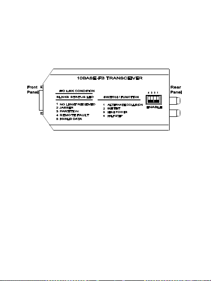
Figure 1 illustrates the top panel of the 3Com
10BASE-FB Transceiver. Table 1 provides a
description of the DIP switches.
Figure 1. Transceiver Top Panel
Page 13

Table 1. Transceiver DIP Switch Settings
Switch Setting Description
1 Alternate
2 SQE Test Enables or disable s SQE
3 High
4 Half Step Enables Half Step Signaling
Collision
Power
Enables or disable s
Alternate collision
Presence Signaling mode.
Test.
Enables High Power.
Disable set tin g invokes
Normal Power.
on AUI Receive (DI) Pa ir.
Disable set tin g invokes Full
Step Signaling.
Page 5
Page 14
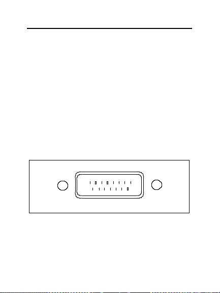
Transce i ver Front Panel
The Transceiver front panel contains the 15-pin
AUI (Attachment Unit Interface) connector. The
AUI 15-pin D subminiature male connector
conforms to IEEE 802.3 and Ethernet Version 2.0
requirements. The shell of the connector is not
insulated from the transceiver case, thereby
providing optimal shielding and minimizing
radiation.
Figure 2 shows the AUI connector on the
Transceiver front panel.
Figure 2. Trans ceiver Front Panel
Page 6
Page 15

Transceiver Rear Panel
The Transceiver rear panel contains the Fiber
Optic (SMA, ST, or FC) connectors and four indicators (LEDs). The LEDs provide status for:
■ Fiber link (transmit and receive)
■ SQE Test
■ Ports
The LEDs can be On, Off, or Blinking. The number of consecutive blinks before a longer pause
on the STA (status) LED indicates the type of failure detected on the link. For ease of interpretation, a table is printed on the top panel of the
transceiver to briefly describe the type of failure.
This table is also repeated in greater detail in the
Troubleshooting section later i n this manual.
Refer to the Troubleshooting section later in this
manual for a description of the LED blink
sequences.
Page 7
Page 16
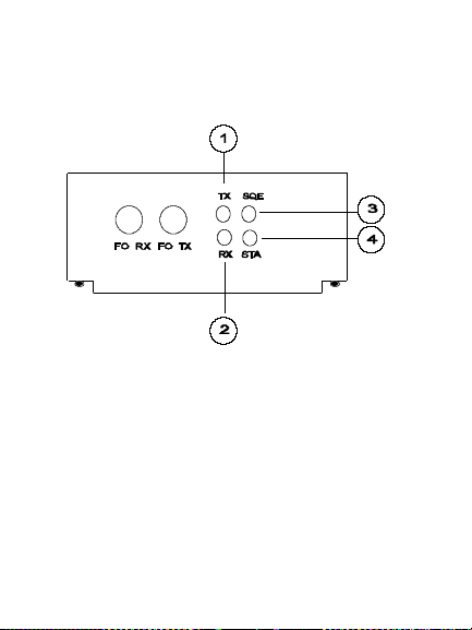
Figure 3 shows the rear panel on the 10BASE-FB
Transceiver. Table 2 provides a description of the
LEDs.
Figure 3. Trans ceiver Rear Panel
Page 8
Page 17

Table 2. Transceiver LED Descriptions
Switch Setting Description
1 TX Transmit Port
2 RX Receive Port
3 SQE Squelch Test
4 STA Status Indicator
Alternate Collision Mode
When enabled, the timing and duration of the
collision presence signal (CI) at the AUI is altered
to facilitate operation with certain controller
chips. The default setting is enabled. When
disabled, collisions are signaled to the AUI for as
long as they last on the medium.
Page 9
Page 18

SQE Te st
When enabled, the collision detection capability
of the transceiver is tested after each transmission. If the test is successful, the SQE test (Signal
Quality Error test, or heartbeat) signal is sent on
the AUI to the attached controller. The default
setting is enabled.
When disabled, this test is not performed and no
SQE test signal is sent to the AUI. Always disable
this function when connecting to an IEEE 802.3
repeater.
High Power (PW R)
When enabled, the optical power output on the
main link is in the High range. The default setting
is disabled, which invokes the optical power
output on the main link in the Normal range.
Page 10
Page 19

Half Step Mode
When enabled, half step is signaled at the
beginning of packets, as re q uired in IEEE 802.3
and Ethernet Version 2.0. The default setting is
enabled.
When disabled, the signaling on the AUI receive
pair (DI) is the same as defined in Ethernet
Version 1.0. This is a full step waveform at the
beginning of a packet.
Installation
This section describes the following considerations for the 10BASE-F B Transceiver:
■ Site Preparation and Placement
■ Unpacking Procedures
Page 11
Page 20

Site Preparation and Placement
The 10BASE-FB Transceiver can be placed in the
following locations:
■ On top of the device to which it is attached
■ On top of a desk
■ Attached directly to the AUI connection on
the DTE
To avoid damage to the Fiber Optic cable and
prevent accidental disconnection from the AUI
cable, secure the transceiver and cables connections.
3Com offers a velcro mount kit
(part # 9 3 0 0-TM3) to secure y our tr ansceiv ers. To
order this kit, contact your supplier or call 3Com
Technical Support.
Page 12
Page 21

Unpacking Procedures
To unpack the transceiver:
1. Remove the unit from the shipping carton.
2. Inspect the unit closely for da mage.
If the unit appears to be damaged, return it
to the shipping carton and conta ct you r local
supplier.
3. Verify that the transceiver is the correct
model by matching the model number listed
on the side of the shipping carton to the
model number you ordered (5101T-FB-SMA,
5101T-FB-ST, or5101T-FB-FC).
Note that the product model number
printed on the shipping box differs from the
model number on the product. The model
number on the shipping box contains the
prefix ’3C9’.
Page 13
Page 22

Verifying Transceiver Switch Settings
Factory-set default settings for the transceiver
are defined in Table 3.
Table 3. Transceiver DIP Switch Default
Settings
Switch Function Default Setting
1 Alter nate
2 SQE Test Enabled
3 High Power Disabled
4 Hal f Step Enabled
Page 14
Collision
Enabled
Page 23

These switch settings typically work with any
Ethernet Version 2.0 or IEEE 802.3 controller
device. You may change the Half Step switch
and Collision Mode switch to optimize operational parameters for a particular controller type.
To make these optimizations, you must know
the following two facts about your Ethernet controller:
1. Is the controller Ether net V2.0 or IEEE
802.3?
Most new products today are based on the
IEEE 802.3 AUI interface standard. Some
controllers are still based on Ethernet V2.0.
Differences exist between the two standards
in AUI pinouts and signaling characteristics.
If you are in doubt, keep the Half Step
switch enabled.
Page 15
Page 24

2. Does the controller use the AMD L ANCE or
Intel 82586 controller chip?
The Transceiver can accommodate certain
operational characteristics of these two
widely used controller chips. The optimizations made by the Transceiver to more suitably support these chips during collision
recovery are not detrimental to operation
with other Ethernet controllers. If there is
any doubt about the type of controller chip
used by your equipment, leave the Alternate
Collision Mode switch enabled.
Page 16
Page 25

Connecting to Ethernet V2.0
and IEEE 802.3 Controllers
Refer to Table 4 for the settings to use for connecting the transceiver to Ethernet Version 2.0
and IEEE 802.3 controller devices.
Table 4. DIP Switch Settings for Ethernet
V2.0 and IEEE 802.3 Controllers
Ethernet
V2.0
Controllers
SQE Test Enabled Enabled
Alternate
Collision Mode
Half Step Mode Enabled May be
* May be Disabled for IEEE compliance.
Enabled * Enabled *
IEEE 802.3
Control lers
Disabled
Page 17
Page 26

Connecting to Ethernet V2.0
and IEEE 802.3 Repeaters
Refer to Table 5 for the settings to use for
connecting the transceiver to Ethernet Version
2.0 and IEEE 802.3 repeaters. The tr ansceiv er DIP
switches must be changed for conn ection to IEEE
802.3 Repeaters.
Table 5. DIP Switch Settings for Ethernet
V2.0 and IEEE 802.3 Repeaters
Ethernet V2.0
Repeaters
SQE Test Disabled * Disabled
Alternate
Collision Mode
Half Step Mode Disabled * Disabled
Disabled * Disabled
IEEE 802.3
Repeaters
Page 18
Page 27

* Functional differences exist whereby
Ethernet V2.0 repeaters are not
suppo rted by the 10BASE-FB
Transceiver. If you are in doubt about
the type of your repeater, contact your
3Com supplier for more information.
Connecting Fiber Cables
To connect fiber cables to the transceiver:
1. Remove the plastic protection caps from the
fiber optic port only when ready to install
cables. Transceiver ports that are not in use
should remain capped.
2. Ensure tha t transmit and receive cables are
clearly marked or color coded and are
connected to the appropriate ports on the
Transceiver.
3. Ensure the cables have been properly
cleaned with an appropriate fiber optic
cleaning solution before installation.
Page 19
Page 28

4. Connect the remote end of the fiber optic
cables to the 10BASE-FB Star Coupler , ONline
Ethernet 10BASE-FB Module, or ONcore
Ethernet 10BASE-FB Module ports. Ensure
the transmit fiber at one end connects to a
receive port at the other end.
Connectin g the AUI Cable
Apply power to the transceiver by connecting it
to:
■ AUI transceiver cables
■ Directly to AUI connectors coming from
active IEEE 802.3/Ethernet nodes
Upon powerup, the transceiver status indicator
and the port status indicator on the other unit
(Star or Ethernet 10BASE-FB Module port) stops
blinking and turns on solid.
Connect the 10BASE-FB Transceiver to an
Ethernet device using proper AUI (transce iver)
cables.
Page 20
Page 29

There are differences between IEEE 802.3 and
Ethernet Version 2.0 AUI cables. While the
10BASE-FB Transceiver is compatible with both,
ensure that the AUI cable being used is appropriate for the device being connected. Refer to the
section, AUI Cables and Pinouts, later in this
manual for cable specifications.
Note: The AUI cable can not exceed 50 meters
in length.
Verif ying Ph ysical Link Ope ration
To verify physical link ope ration:
1. Verify that every transceiver on the network
has its status indicator ON and not blinking.
2. Verify that each 3Com 10BASE-FB Sta
Coupler or Ethernet 10 BA SE-FB Module port
status indicator is ON and not blinking.
If after completing Steps 1 and 2 you find no
blinking Status indicators, you can now use your
network nodes and verify data connectivity.
Page 21
Page 30

If after completing Steps 1 and 2 you find blinking Status indicators on connected and enabled
modules or devices, refer to the Troubleshooting
section in this manual.
Troubleshooting
This section explains how to use the diagnostic
features of the 10BASE-FB Transceiver for fault
isolation. This section describes:
■ Status LED
■ Troubleshooting Fiber Links
■ System Problems
Status LED
The 10BASE-FB Transceiver provides a
diagnostic status LED that indicates link status.
The normal state for this indicator is the steady
ON state. If the LED is OFF, this usually indicates
lack of power.
Page 22
Page 31

A blinking status indicator is always a sign of a
detected problem.
The status of the 10BASE-FB Transceiver can be
easily and quickly determined by scanning for a
blinking LED. Interpretation of the blinking
sequences is provided in Table 6 and is also
printed on the Transceiver top panel.
Ta ble 6 lists the most common cause s of link
failures and the steps that should be taken to
correct them. If the indicat or r emains off or none
of the possible problems listed in Table 6 apply,
try another port on the connecting device or
replace the Transceiver.
Page 23
Page 32

Table 6. Troubleshooting Using the
Status LEDs
LED
Indicates
Status
Off No power Computer
Possible
Problem
not powered
Disconnected
AUI cable
Broken AUI
cable
Bad
controller
Page 24
Possible
Solution
Turn on the
computer
Check AUI
conne c ti on
Replace AUI
cable
Follow
vendor’s
instructions
Page 33

Table 6. Troubleshooting Using the
Status LEDs
LED
Indicates
Status
1 Blink No light
received
2
Jabber Jabbering
Blinks
3
Partition Bad port on
Blinks
Possible
Problem
Bad fiber
connections
Broken fiber Check and fix
Bad port on
other end
controller
Noisy AUI
cable
other end
Possible
Solution
Clean RX
fiber on
both ends
RX fiber link
Try another
port or
replace unit
Follow
vendor’s
instructions
Replace AUI
cable
Try another
port or
replace unit
Page 25
Page 34

Table 6. Troubleshooting Using the
Status LEDs
LED
Status
4
Blinks
5
Blinks
Page 26
Indicates
Remote
fault
Invalid
data
Possible
Problem
Bad fiber
connections
Bad port on
other end
Broken fiber Check and fix
Bad fiber
connections
Possible
Solution
Clean TX
fiber on
both ends
Try another
port or
replace unit
TX fiber link
Clean RX
fiber on
both ends
Page 35

Table 6. Troubleshooting Using the
Status LEDs
LED
Status
5
Blinks
(con’t)
Indicates
Invalid
data
Possible
Problem
Broken or
degraded
fiber
Bad or
degraded
port on other
end
Possible
Solution
Check and fix
RX fiber link
Try another
port or
replace unit
Troubleshooting Link Problems
Each full duplex fiber link is monitored at both
ends. The 1 0B ASE-FB Star Coupler and the 3Com
Ethernet 10 BASE-FB Modules contain status
indicators (one for each port). The Transceiver
contains a single status indicator. In addition to
signifying link problems, the T r an sceiver indica tor
also indicates a local or remote jabber condition.
Page 27
Page 36

All link problems cause the link to be inoperable.
If a link problem is indicated, check the indica tors
at both sides of the link, and then consult
Table 6.
Troubleshooting System Problems
This section addresses some of the system
problems that can be corrected using the options
on the 10BASE-FB Transceiver. If problems occur,
always check the diagnostics indicators on the
Transceiver.
Excessive Collisions
Collisions can be caused by loops in the
10BASE-FB network. Such loops cause every
packet to collide with itself. If you cannot locate
the loop, try segmenting your network (by disconnecting Star Couplers, or ONline and ONcore
Hubs one at a time) until the loop is located.
Page 28
Page 37

If you have IEEE 80 2.3 repea ters in you r netw ork,
ensure that the SQE Mode and Alternate Collision Mode switches are disabled for 10BASE-FB
Transceivers connected to these repeaters.
Late Collisions and Failure to Defer
Late collisions ca n be caused by exceeding the
distance rules of Ethernet, or by controllers that
do not fully comply 100% with the IEEE standard.
To verify that your network satisfies the distance
rules, refer to the configuration rules in:
■ 10BASE-FB Star Coupler Installation and
Operation Guide, Chapter 6
■ ONline or ONcore Ethernet 10BASE-FB
Module Installation Guide, Chapter 2
Activating the Alternate Collision Mode on the
Transceiver may solve this problem in many
cases.
Page 29
Page 38

Also, ensure that you have accounted for the
distance reduction caused by external baseband
repeaters that were added and by baseband
segments connected to those repeaters.
Miscellaneous Errors
Many types of physical layer errors can occur if
the controller AUI interfac e is Ethernet Version
1.0 or not fully compliant with Version 2.0 and
IEEE 802.3.
If errors occur:
1. Try switching between the Full Step and Half
Step options on the 10BASE-FB Transce iver.
2. Verify that an IEEE 802.3 AUI cable is being
used with 802.3 controllers
3. Verify that Ethernet V2.0 cables are being
used with Ethernet V2.0 controllers.
Refer to the next section for more information
on AUI cables.
Page 30
Page 39

Transceiver Cables
This section explains the signal differences
among the various types of AUI transceiver
cables. It also explains wire sizes and the proper
pinouts for Ethernet Version 2.0 and IEEE 802.3
AUI cables.
Signal Differ en ces
Signal differences occur between different types
of transceiver cables because there are three
Ethernet standards:
■ V1.0
■ V2.0
■ IEEE 802.3
These three standards also affect the shielding
and grounding of the cables and the size of the
wires used in the cables.
The most significant difference among AUI
Page 31
Page 40

cables occurs in the shielding and grounding of
the individual signal and power pairs. IEEE 802.3
and Ethernet V2.0 specify a requirement for
signal isolation due to AC-coupling of the AUI
connection. The V1.0 standard does not contain
this requirement.
The three standards specify different techniques
for shielding and grounding.
EEE 802.3
All shields of the individual signal and power
pairs are connected to pin 4. The overall AUI
cable shield is connected to the AUI connector
shell to provide a cable ground. Pin 1 is not used.
Version 2.0
All shields are connected to pin 1 and the AUI
connector shell. Pin 4 is not used. Most Ethernet
cables are built this way.
Version 1.0
Page 32
Page 41

Shielding of individual signal or power pairs is
not required because most V1.0 controllers and
transceivers are DC-coupled. The overall AUI
cable shield provides for shielding and grounding
and is connected to pin 1 and the AUI connector
shell.
In practice, most Ethernet V1.0 equipment uses
version 2.0 cables due to cross-talk problems
caused by the lack of individual shielding of the
pairs in Version 1.0 cables.
Wire Sizes
The three versions of AUI cables also use different wire sizes for the signal and power pairs.
Table 7 describes the wiring that each type of
transceiver cable uses.
Page 33
Page 42

Table 7. Transceiver Cable Wire Sizes
Cable Type Signal Pair Power Pair
V1.0 AWG # 22 AW G # 20
V2.0 and IEEE 802.3 AWG # 2 0 AWG # 2 0
Non-stan dard
“office” ca ble *
* More flexible, but is limited to 5.0
meters in length.
AWG # 24 * AWG #24 *
Signal deterioration along the signal pairs is most
likely to happen as the AUI cable reaches the
maximum length of 50 meters. Signal deterioration is due to the filtering action of the cable.
IEEE 802.3 AUI cables a re designed to reduce
this effect.
Page 34
Page 43

Because 802.3 AUI cables provide a ground
shield isolated from the signal and power pair
shields, the cables provide additional noise
immunity in noisy operating environments.
Cable Pinouts
Table 8 shows the proper pinouts for Ethernet
Version 2.0 and IEEE 802.3 AUI cables.
Table 8. AUI Cable Pinout Chart
Pin 802.3 V2.0, V1.0
1CI-SShield
2 CI-A Collision Presence +
3 DO-A Transmit +
4 DI-S Reserved
5 DI-A Receive +
6 V Power Return
Page 35
Page 44

Table 8. AUI Cable Pinout Chart
Pin 802.3 V2.0, V1.0
7CO-AReserved
8CO-SReserved
9 CI-B Collision Presence 10 DO-B Tran smit -
802.3 - All signal and power pair shields can be
connected to pin 4. The braided AUI cable shield
connects to the AUI shell and not to pin 1.
V2.0 - All shields (external and internal) connect
to pin 1 and to the connector shell.
V1.0 - Braided AUI cable shield connects to
connector shield and pin 1.
Page 36
Page 45

Troubleshooting Transceiver Cables
This section describes some of the common
problems you may have with transceiver cables
and provides possible solutions to the problems.
Sympto ms of Faulty Transceiver Cables
The follow ing list describes symptoms of faulty
transceiver cables:
■ False or excessive collisions.
■ Jabber condition on transceiver.
■ Receive Errors (CRC and Alignment).
■ Severe degradation of system performance
Page 37
Page 46

Causes of Fault Transceiver Cables
The follow i ng list describes causes of faulty transceiver cables:
■ Improper Grounding (pin 1 vs. pin 4).
■ Bad ground:
■ Shell connector not crimped onto AUI
cable braid.
■ Ribbon cables in computers not shielded
or improperly mounted.
■ Broken pair wires or unseated AUI connec-
tor pin.
■ Improper pairing - Verify that signal and
power wires are paired (for example,
Transmit + paired with Transmit -)
■ Individual pairs not individually shielded (for
example, Ethernet V1.0 type cable).
Page 38
Page 47

Cable Recommendations
The 10BASE-FB Transceiver is fully compatible
with IEEE 802.3 and Ethernet V2.0. The use of
Ethernet V1.0 AUI cables and cont rollers is not
recommended.
The 10BASE-FB Transceiver accepts either 802.3
or V2.0 AUI cables. Use the proper AUI cable for
the appropriate controller being used. For example, if you use an 802.3 controller, then use an
802.3 AUI cable.
Specifications
This section lists the following specifications for
the 10BASE-FB Transceiver:
■ General
■ Optical Interface
■ Transmit Power
■ Fiber Optic Cable Compatibility
Page 39
Page 48

■ Attachment Unit Interface
General Specifications
Table 9. General Specifications
Specification Value
Dimensions 4.8" x 2.4" x 0.9"
Weight 4 oz. (115 g)
Operating Temperature 32° to 104° F
Operating Humi di t y Less tha n 95%
Power 5 Watts
Page 40
(122mm x 61mm x
23mm)
(0° to 40° C)
non-condensing
Page 49

Optical Interface Specifications
Table 10. Optical Interface Specifications
Specification Value
Data Rate 10 Mi llion bits per second
Encoding Compliant with 10BASE-FB
Connector s SMA, ST, and FC
Connectors spacing 0.8 inch
Tran smit Source Type GaAlAs LED
Transmit Wavele n g th 820
Receiver Detector Type Silicon PIN photodiode
Receive Power for
better than 10
err or rate (minimal
guarantee d dynam ic
range)
-9
synchronous signaling
standard
-29.5 dBm peak to
bit
-9 dBm peak
± 20nm
Page 41
Page 50

Transmit Power Specifications
Tab le 11. Transmit Power
Cable Size
(micron)
50/125 NA 0.20 -21.3 ± 2.5 -13.8 ± 1. 5
62.5/125 NA 0.275 -17.5 ± 2.5 -10.5 ± 1.5
100/140 NA 0.30 -12.0 ± 2.5 -5.0 ± 1.5
Normal
Power
(dBm Peak)
High Power
(dBm Peak)
Fiber Optic Cables Compatibility
Tab le 12. Fiber Optic Cable Specifications
Specification Value
Cable size 50/125, 62.5/ 125, 100/140
Cable bandwidth 40 MHzKm minimum
Jabber protection 30 ± 3 msec (Non-Latching)
Page 42
micron diameter
Page 51

Attachme nt Unit Interfa ce Specifications
Table 13. AUI Specifications
Specification Value
Connector Standard male 15-pin
Standards
conformance
DC Power
requirements
DC line
current
consumption
D-subminiature
IEEE 802.3, Ethernet V2.0
12-15 Volts ± 10% applied at AUI
(pins 13, 6)
200 mA min @ 16.5 V, 77° F (25° C)
300 mA typ @ 12.0 V, 77° F (25° C)
500 mA max @ 10.8 V, 77° F (25° C)
Page 43
Page 52

 Loading...