

Page 1

®
ONline Ethernet Management
Module Installation and
Operation Guide
Document Number 17-00087-7
Printed March 1995
Model Number: 5101M-MGT
Software Version: 4.0
3Com Co rporation
118 Turnpike Road
Southbo rough, MA 0177 2-1886
U.S.A.
(508) 46 0- 8900
FAX (508) 460-8950
Page 2

Federal Communications Comm ission
Notice
This equipment has been tested and found to comply with the
limits for a Class A digital device, pursuant to Part 15 of the FCC
Rules. These limits are designed to provide reasonable protection
against harmful interference when the equipment i s operated in a
commercial environment. This equipment generates, uses, and can
radiate radio frequency energy and, if not installed and used in
accordance with the instruction manual, may cause harmful
interference to rad io communications. Operation of this equipment
in a residential area is likely to cause harmful interfer ence, in which
case you must correct the interference at your own expense.
Canadian Emissions Requirements
Cet appareil numérique respecte les limites de bruits
radioélectriques applicables aux appareils numériques de Classe A
prescrites dans la norme sur la matériel brou illeur: "Appareils
Numériques", NMB-003 édictée par le Ministère des
Communications.
This digital apparatus does not exceed the Class A limits for radio
noise emissions from digital apparatus as set out in the
interference-causing equipment standard entitled "Digital
Apparatus", ICES-003 of the Department of Communications.
VDE Class B Compl ianc e
Hiermit wird bescheinigt, dass der 5101M-MGT in
Üebereinstimmung mit den Bestimmungen der Vfg 243/1991
funkentstöert ist.
Der Deutschen Bundespost wurde das Inverkehrbringen dieses
Geraetes angezeigt und die Berechtigung zur Üeberprüefung der
Serie auf Einhaltung der Bestimmungen eingeräeumt.
Einhaltung mit betreffenden Bestimmugen kommt darauf an, dass
geschirmte Ausfuehrungen gebraucht werden. Fuer die
Beschaffung richtiger Ausfuehrungen ist der Betreiber
verantwortlich.
This is to certify that the 5101M-MGT is shielded against radio
interference in accordance with the provisions of Vfg 243/1991.
The German Postal Services have been advised that this equipment
is being placed on the market and that they have been given the
right to inspect the series for compliance with regulations.
Compliance with applicable regulations depends on the use of
shielded cables. The user is responsible for procuring the
appropriate cables.
EN55022/CISPR22 Com p lian ce
This equipment conforms to the Class A emissions limits for a
digital device as defin ed by EN55022 (CISPR22).
VCCI Class 1 Com pl ian c e
This equipment is in the 1st Class category (information equipment
to be used in commercial or industrial areas) and conforms to the
standards set by the V oluntary Control Council for Inter fere nce by
Information Technology Equipment aimed at preventing radio
interference in commercial or industrial areas.
Consequently, when the equipment is used in a residential area or
in an adjacent area, r adio interferenc e may be caused to radio and
TV receivers, and so on.
Read the instructions for correct handling.
UK General Approval Statem en t
The ONcore Switching Hub, ONline System Concentrator, and
ONsemble StackSyste m Hub are manufactur ed to the International
Safety Standard EN 60950 and are approve d in the UK under the
Genera l Approval Number NS/G/12345/J/100003 for indirect
connection to the public telecommunication network.
Disclaimer
The information in this document is subject to change without
notice and should not be construed as a commitment by 3Com
Corporation. 3Com Corporation assumes no responsibility for any
errors that may appear in this document.
Copyright Statement
©
1995, by Chipcom Corporation, a subsidiary of 3Com
Corporation. Printed in U.S.A. All rights reserved. 3Com is a
registere d trade mark of 3Com Corporat ion. ONcore is a registered
trademark of Chipcom Corporation. The information contained
herein is the exclusive and confidential property of 3Com
Corporation. No part of this manual may be disclosed or
reproduced in whole or in part without permission from 3Com
Corporation.
Trademarks
Because of the nature of this material, numerous hardware and
software products are mentioned by name. In most, if not all
cases, these product names are claimed as trademarks by the
companies that man ufacture the products. It is not our intent to
claim these names or trademarks as our own.
Artel, Chipcom, Ethermo dem, Galactica, ONcore, ORnet,
StarBridge, and Tr iChannel are reg ister e d tra demark s of C hipcom
Corporation.
Chipcom OpenHub, G-Man, LANsentry, MultiProbe, ONdemand,
ONline, ONsemble, PowerRing, SL2000, SL3000, SL4000,
ii ONline Ethernet Management Module Installation and Operation Guide
Page 3

StackJack, StackSystem, and SwitchC entral are trademarks of
Chipcom Corporation.
The Chipcom Multichannel Architecture Communications System is
registered under U.S. Patent Number 5,301,303.
DEC, DECnet, the Digital logo, DELNI, POLYCENTER, VAX, VT100,
and VT220 are trademarks of Digital Equipment Corporation.
IBM is a registered trademark of International Business Machines.
NetView is a trademark of International Business Machines.
ST is a registerd trademark of AT&T.
UNIX is a registered trademark in the U.S.A. and other countries
licensed exclusively through X/Open Company, Ltd.
XNS is a trade mark a nd Ethernet is a r egistered trademark of Xerox
Corporation.
3ComFacts, Ask 3Com, CardFacts, NetFacts, and CardBoard are
service marks of 3Com Corporation.
3Com, LANplex, BoundaryRouting, LanScanner, LinkBuilder,
NETBuilder, NETBuilderII, ParallelTasking, ViewBuilder, EtherDisk,
Etherl\Link, Ether Link Plus, EtherLink II, TokenLink, T okenLink Plus,
and TokenDisk are registered trademarks of 3Com Corporation.
3ComLaser Library, 3TECH, CacheCard, FDDILink, FMS, NetProbe,
SmartAgent, Star-Tek, and Transcend are trademarks of 3Com
Corporation.
CompuServe is a registered trademark of CompuServe, Inc.
3Com registered trademarks are registered in the United States,
and may or may not be register ed i n other countrie s. Other brand
and product names may be reg istered tradema rks or trademark s of
their respective holders.
Restricte d Righ ts
Use, duplication, or disclosure by the Government is s ubject to
restrictions as set forth in subparagraph (c)(1) (ii) of the Rights in
Technical Data and Computer Software clause at
DFARS 252.227-7013.
Printed on recycled paper.
ONline Ethernet Management Modul e Installation and Operation Guide iii
Page 4

iv ONline Ethern et Management Mo dule Installation and Operation Guide
Page 5

How to Use This Guide
Audience . . . . . . . . . . . . . . . . . . . . . . . . . . . . . . . . . . . . . . . . . . . . . . . . .xiv
Structure of This Guid e . . . . . . . . . . . . . . . . . . . . . . . . . . . . . . . . . . . . . . .xiv
Document Conventions . . . . . . . . . . . . . . . . . . . . . . . . . . . . . . . . . . . . . . xv
Related Documents . . . . . . . . . . . . . . . . . . . . . . . . . . . . . . . . . . . . . . . . xvii
3Com Documents . . . . . . . . . . . . . . . . . . . . . . . . . . . . . . . . . . . . . . xviii
Reference Documents . . . . . . . . . . . . . . . . . . . . . . . . . . . . . . . . . . . . xviii
Chapter 1 — Introduction
The ONline Ethernet Managem ent Module . . . . . . . . . . . . . . . . . . . . . . . 1-1
Theory of Operation . . . . . . . . . . . . . . . . . . . . . . . . . . . . . . . . . . . . . 1-3
Complete ON lin e C on trol . . . . . . . . . . . . . . . . . . . . . . . . . . . . . . . . . 1-5
ONline Ethernet Management Mo du le Versions . . . . . . . . . . . . . . . . 1-5
The EMM Starter Version . . . . . . . . . . . . . . . . . . . . . . . . . . . . . . 1-5
The EMM Basic Version . . . . . . . . . . . . . . . . . . . . . . . . . . . . . . . 1-6
The EMM Advanced Version . . . . . . . . . . . . . . . . . . . . . . . . . . . . 1-6
Network Management Access . . . . . . . . . . . . . . . . . . . . . . . . . . . . . . . . 1-7
Network Management Functions . . . . . . . . . . . . . . . . . . . . . . . . . . . 1-7
ONline Backplane Archi tectu r e . . . . . . . . . . . . . . . . . . . . . . . . . . . . . . . . 1-8
Where To Go From Here . . . . . . . . . . . . . . . . . . . . . . . . . . . . . . . . . . . 1-12
Contents
Chapter 2 — Unpacking and Installin g the Mod ul e
Precautionary Procedures . . . . . . . . . . . . . . . . . . . . . . . . . . . . . . . . . . . . 2-1
Unpacking Procedu re . . . . . . . . . . . . . . . . . . . . . . . . . . . . . . . . . . . . . . . 2-2
Installation Procedures . . . . . . . . . . . . . . . . . . . . . . . . . . . . . . . . . . . . . . 2-3
Verifying Operatio n . . . . . . . . . . . . . . . . . . . . . . . . . . . . . . . . . . . . . 2-5
The EMM Front Panel . . . . . . . . . . . . . . . . . . . . . . . . . . . . . . . . . . . . . . . 2-6
Status LED . . . . . . . . . . . . . . . . . . . . . . . . . . . . . . . . . . . . . . . . . 2-7
Master Mgt Module LED . . . . . . . . . . . . . . . . . . . . . . . . . . . . . . . 2-7
Download in Progress LED . . . . . . . . . . . . . . . . . . . . . . . . . . . . . 2-8
ONline Ethernet Management Module Installation and Operation Guide v
Page 6

Reset Button . . . . . . . . . . . . . . . . . . . . . . . . . . . . . . . . . . . . . . . . 2-8
RS-232 Serial Port . . . . . . . . . . . . . . . . . . . . . . . . . . . . . . . . . . . . 2-8
Where to go From Here . . . . . . . . . . . . . . . . . . . . . . . . . . . . . . . . . . . . . 2-9
Chapter 3 — Startup and Management Functions
Quick Reference for Getti ng Starte d . . . . . . . . . . . . . . . . . . . . . . . . . . . . 3-2
Saving and Reverting Configuratio n Values . . . . . . . . . . . . . . . . . . . . 3-3
Configuring the Terminal . . . . . . . . . . . . . . . . . . . . . . . . . . . . . . . . . . . . 3-4
Optional Termi nal Setting s . . . . . . . . . . . . . . . . . . . . . . . . . . . . . . . . 3-6
Setting Terminal Hang up . . . . . . . . . . . . . . . . . . . . . . . . . . . . . . 3-6
Setting Terminal Promp t . . . . . . . . . . . . . . . . . . . . . . . . . . . . . . . 3-7
Setting Terminal Tim eo ut . . . . . . . . . . . . . . . . . . . . . . . . . . . . . . 3-7
Configuring the EMM . . . . . . . . . . . . . . . . . . . . . . . . . . . . . . . . . . . . . . 3-7
Setting Device Password . . . . . . . . . . . . . . . . . . . . . . . . . . . . . . . . . . 3-9
Establishing the Administrator Password . . . . . . . . . . . . . . . . . . 3-10
Establishing the User Password . . . . . . . . . . . . . . . . . . . . . . . . . 3-11
Assigning an EMM Name . . . . . . . . . . . . . . . . . . . . . . . . . . . . . . . . 3-12
Setting Device Diagnostics . . . . . . . . . . . . . . . . . . . . . . . . . . . . . . . 3-12
Assigning a Contact N am e and Locatio n . . . . . . . . . . . . . . . . . . . . . 3-12
Configuring SNMP Values . . . . . . . . . . . . . . . . . . . . . . . . . . . . . . . . . . 3-13
Assigning IP Addresses . . . . . . . . . . . . . . . . . . . . . . . . . . . . . . . . . . 3-15
Creating a Community Table . . . . . . . . . . . . . . . . . . . . . . . . . . . . . 3-15
Configuring the Alert Setting . . . . . . . . . . . . . . . . . . . . . . . . . . . . . 3-15
Setting a Subnetwork Mask . . . . . . . . . . . . . . . . . . . . . . . . . . . . . . 3-16
Defining the Default Gateway . . . . . . . . . . . . . . . . . . . . . . . . . . . . 3-16
Enabling Trap Receive . . . . . . . . . . . . . . . . . . . . . . . . . . . . . . . . . . . 3-16
Configuring Modules and Ports . . . . . . . . . . . . . . . . . . . . . . . . . . . . . . 3-17
Assigning Modu le Networks . . . . . . . . . . . . . . . . . . . . . . . . . . . . . . 3 -17
Assigning Module Mastersh ip Prio rity . . . . . . . . . . . . . . . . . . . . . . . 3-18
Setting Port Mode . . . . . . . . . . . . . . . . . . . . . . . . . . . . . . . . . . . . . 3 -19
Setting Port Network . . . . . . . . . . . . . . . . . . . . . . . . . . . . . . . . . . . 3-19
Setting Redundant Ports . . . . . . . . . . . . . . . . . . . . . . . . . . . . . . . . . 3-19
Configuring Address-to-Port Sec urit y . . . . . . . . . . . . . . . . . . . . . . . . . . 3-20
Managing Security with EMM Master and Slaves . . . . . . . . . . . . . . 3-21
Establishing Rem ot e Logins . . . . . . . . . . . . . . . . . . . . . . . . . . . . . . . . . 3-22
Logging Out From a Remote Session . . . . . . . . . . . . . . . . . . . . . . . 3-24
Monitoring With SHOW Commands . . . . . . . . . . . . . . . . . . . . . . . . . . . 3-24
Showing Device Informa t ion . . . . . . . . . . . . . . . . . . . . . . . . . . . . . . 3 -24
vi ONline Ethernet Management Module Installation and Operation Guide
Page 7

Showing Mod ule Informa t ion . . . . . . . . . . . . . . . . . . . . . . . . . . . . . 3 -25
Showing Port Inform atio n . . . . . . . . . . . . . . . . . . . . . . . . . . . . . . . . 3-26
Showing Conc entr at or Information . . . . . . . . . . . . . . . . . . . . . . . . 3 -26
Showing Coun ter Statistic s . . . . . . . . . . . . . . . . . . . . . . . . . . . . . . . 3-27
Using the MONI TO R Co mm and . . . . . . . . . . . . . . . . . . . . . . . . . . . 3 -28
Where To Go From Here . . . . . . . . . . . . . . . . . . . . . . . . . . . . . . . . . . . 3-28
Chapter 4 — Troubleshooting
Applying Power . . . . . . . . . . . . . . . . . . . . . . . . . . . . . . . . . . . . . . . . . . . 4-1
EMM and Terminal Interface . . . . . . . . . . . . . . . . . . . . . . . . . . . . . . . . . 4-3
EMM Trap Messages . . . . . . . . . . . . . . . . . . . . . . . . . . . . . . . . . . . . . . . 4-5
Technical Assistance . . . . . . . . . . . . . . . . . . . . . . . . . . . . . . . . . . . . . . . . 4-7
EMM Network Impact . . . . . . . . . . . . . . . . . . . . . . . . . . . . . . . . . . . . . . 4-7
3Com Protocols . . . . . . . . . . . . . . . . . . . . . . . . . . . . . . . . . . . . . . . . 4-8
Chapter 5 — Software Download Instructions
Download Requ irements . . . . . . . . . . . . . . . . . . . . . . . . . . . . . . . . . . . . 5-2
How the FDK and UDK Process Works . . . . . . . . . . . . . . . . . . . . . . . 5-3
Out-of-Band Do wn load Instru ctions . . . . . . . . . . . . . . . . . . . . . . . . . . . . 5-4
Installing the ProComm Software . . . . . . . . . . . . . . . . . . . . . . . . . . . 5-4
Connect the RS-23 2 Cabl e . . . . . . . . . . . . . . . . . . . . . . . . . . . . . . . . 5-8
Preparing to Download the New Software . . . . . . . . . . . . . . . . . . . . 5-8
Downloading the New Software . . . . . . . . . . . . . . . . . . . . . . . . . . . 5-11
Inband Downl oad In structions . . . . . . . . . . . . . . . . . . . . . . . . . . . . . . . 5-15
Troubleshooting . . . . . . . . . . . . . . . . . . . . . . . . . . . . . . . . . . . . . . . . . . 5-19
ProComm Problems . . . . . . . . . . . . . . . . . . . . . . . . . . . . . . . . . 5-20
Ethernet Managemen t Modu le Problems . . . . . . . . . . . . . . . . . 5-21
Appendix A — Specifications
General Specifications . . . . . . . . . . . . . . . . . . . . . . . . . . . . . . . . . . . . . . A-1
Electrical Specifications . . . . . . . . . . . . . . . . . . . . . . . . . . . . . . . . . . . . . . A-2
Environmental Spec ific ation s . . . . . . . . . . . . . . . . . . . . . . . . . . . . . . . . . A-2
Mechanical Specificatio ns . . . . . . . . . . . . . . . . . . . . . . . . . . . . . . . . . . . .A-3
Hardware Specifications . . . . . . . . . . . . . . . . . . . . . . . . . . . . . . . . . . . . .A-3
Memory . . . . . . . . . . . . . . . . . . . . . . . . . . . . . . . . . . . . . . . . . . .A-3
Special Circuits . . . . . . . . . . . . . . . . . . . . . . . . . . . . . . . . . . . . . .A-3
ONline Ethernet Management Module Installation and Operation Guide vii
Page 8

Appendix B — RS-232 Cable Specs and Modem Use
RS-232 Cable Specification s . . . . . . . . . . . . . . . . . . . . . . . . . . . . . . . . . . B-1
Modem Use . . . . . . . . . . . . . . . . . . . . . . . . . . . . . . . . . . . . . . . . . . . . . . B-2
Appendix C — MIB Group s
MIB-II Grou p s . . . . . . . . . . . . . . . . . . . . . . . . . . . . . . . . . . . . . . . . . . . . . C-1
3Com MIB G roups . . . . . . . . . . . . . . . . . . . . . . . . . . . . . . . . . . . . . . . . . C-2
Appendix D — Technical Support
On-line Technical Support . . . . . . . . . . . . . . . . . . . . . . . . . . . . . . . . . . .D-1
Email Technical Support . . . . . . . . . . . . . . . . . . . . . . . . . . . . . . . . . . D-2
World Wide Web Site . . . . . . . . . . . . . . . . . . . . . . . . . . . . . . . . . . . . D-2
Support from Your Netw ork Sup plier . . . . . . . . . . . . . . . . . . . . . . . . . . . D-2
Support from 3Com . . . . . . . . . . . . . . . . . . . . . . . . . . . . . . . . . . . . . . . .D-3
Returning Produ cts for Repair . . . . . . . . . . . . . . . . . . . . . . . . . . . . . . . . . D-4
Accessing the 3Com MIB . . . . . . . . . . . . . . . . . . . . . . . . . . . . . . . . . . . .D-4
3Com Technical Publications . . . . . . . . . . . . . . . . . . . . . . . . . . . . . . . . . D-5
Index
viii ONline Ethernet Management Module Installatio n and Operation Guide
Page 9

Figures
Figure 1-1. EMMs in Network Config uration . . . . . . . . . . . . . . . . . . 1-3
Figure 1-2. Ethernet Management Module Communication in the
Figure 1-3. TriChannel Backplane Archit ectu re Assignments . . . . . . . 1-9
Figure 2-1. Installing the Ethernet Management Module . . . . . . . . . . 2-4
Figure 2-2. Installed EMM Connected to a Terminal . . . . . . . . . . . . . 2-5
Figure 2-3. Ethernet Management Module Faceplate . . . . . . . . . . . . 2-6
Figure 3-1. The 17-Slot ONline System Con cent rator . . . . . . . . . . . . 3-8
Figure 3-2. The 6-Slot ONline System Concentrat or . . . . . . . . . . . . . 3-9
Figure 3-3. The 6-Slot ONline System Concentrator with Integrated
Figure 3-4. Sample Remote Conn ec tio n . . . . . . . . . . . . . . . . . . . . . 3-23
Figure 5-1. Initial Installation Screen . . . . . . . . . . . . . . . . . . . . . . . . . 5-5
Figure 5-2. ProComm Installatio n Scr een . . . . . . . . . . . . . . . . . . . . . 5-7
Figure 5-3. Post-ProComm Installation Screen . . . . . . . . . . . . . . . . . . 5-7
Figure 5-4. Initial UDK Installation Screen . . . . . . . . . . . . . . . . . . . . . 5-9
Figure 5-5. ProComm Status Line Screen . . . . . . . . . . . . . . . . . . . . 5-10
Figure 5-6. ProComm Menu Screen . . . . . . . . . . . . . . . . . . . . . . . . 5 -13
Figure 5-7. ProComm Downl oad Screen . . . . . . . . . . . . . . . . . . . . . 5-14
Figure 5-8. Exit ProComm Screen . . . . . . . . . . . . . . . . . . . . . . . . . . 5-14
Figure 5-9. UDK Completion Screen . . . . . . . . . . . . . . . . . . . . . . . . 5-15
Figure B-1. Management Interface RS-232 Connector and Cable
ONline System Concentrator . . . . . . . . . . . . . . . . . . . . . . 1-3
Controller . . . . . . . . . . . . . . . . . . . . . . . . . . . . . . . . . . . . 3-9
Pinouts . . . . . . . . . . . . . . . . . . . . . . . . . . . . . . . . . . . . . . B-2
ONline Ethernet Management M odule Installation and Operation Guide ix
Page 10

x ONline Ethernet Management Module Installation and Operation Guide
Page 11

Tables
Table 1-1. Ethernet Backp lane Combination Reference Chart. . . . . 1-10
Table 1-2. Token Ring Backplane Com bination Reference
Chart . . . . . . . . . . . . . . . . . . . . . . . . . . . . . . . . . . . . . . . 1-10
Table 1-3. FDDI Backplane Combination Reference Chart. . . . . . . . 1-11
Table 2-1. Interpretation of the Ethernet Management Module
LEDs . . . . . . . . . . . . . . . . . . . . . . . . . . . . . . . . . . . . . . . . 2-7
Table 3-1. Quick Reference for Getting Started. . . . . . . . . . . . . . . . . 3-2
Table 3-2. EMM Terminal Parameter Options and
Factory Defaults. . . . . . . . . . . . . . . . . . . . . . . . . . . . . . . . 3-5
Table 4-1. Applying Power Suggestions . . . . . . . . . . . . . . . . . . . . . . 4-2
Table 4-2. EMM Terminal Interface Suggestions . . . . . . . . . . . . . . . . 4-3
Table 4-3. EMM Trap Message Fields . . . . . . . . . . . . . . . . . . . . . . . . 4-6
Table 5-1. UDK Er ror Messages . . . . . . . . . . . . . . . . . . . . . . . . . . . 5-20
Table 5-2. EMM Down load Error Message s . . . . . . . . . . . . . . . . . . 5-22
Table B-1. RS-232 Cable Gu idelin es . . . . . . . . . . . . . . . . . . . . . . . . . B-1
ONline Ethernet Management M odule Installation and Operation Guide xi
Page 12

Page 13

How to Use This Guide
This guide presents the principal features of the 3Com ONline™ Ethernet
Network Management Module (EMM) for version 4.0 software. It includes
instructions for installing the EMM into the ONline System Concentrator
and it also gives a physical description of the EMM, including the LEDs,
Reset Button, and RS-232 serial port con nector on the mo dule faceplate.
Instructions are also provided for using the EMM to manage the
concentrator through a terminal connected to the RS-232 serial port
connector. The commands used to configure the EMM to manage the
concentrator and modules are described in Chapter 3.
Troubleshootin g procedures that may help diagnose problem s during
installation and d uring operation are provided in Chapter 4.
A complete set of alphabetized ONline management commands is provided
in the ONline Management Commands Guide (17-00403). Each command
is described in detail with examp les of its syntax, options, and use.
ONline Ethernet Management Module Installation and Operation G uide xiii
Page 14

Audience
This guide is intended for the following people at your site:
❑ Network manager or administrator
❑ Hardware installer
Structure of This Guide
This guide contains five ch apters, three append ices, and an index:
Chapter 1 - Introduction – Presents the key features and management
functions of the EMM.
Chapter 2, Unpacking a nd Installing the Module – Pr ovides illustrated
procedures for installing the EMM into the ONline System Concentrator.
This chapter also describes the front panel in dic ators (LEDs), the Reset
Button, and RS-232 serial port connector. It also explains how to connect a
terminal to the EMM.
Chapter 3, Startup and Management Functions – Explains how to
configure the EMM to manage an Ethernet network. These configurations
include terminal settings, default system values, and configuring the EMM
for communication with SNMP-based management systems. This chapter
also describes how to monitor your Ethernet network using the SH O W
commands.
Chapter 4, Troubleshooting – Provides help in isolating and correcting
problems that may arise during installation and during normal operation.
Chapter 5, Software Download Instructions – Explains how to
download new software code to the Flash EPROM in th e EMM.
Appendix A, Specifications – Provides tech nical specification s for the
EMM, such as the electrical and environmental specifications.
xiv ONline Ethernet Management Module Installation and Operation Guide
Page 15

Appendix B, RS-232 Cable Specification and Modem Use –Describes
the various RS-232 cable configurations that can be used to connect a
device to the EMM serial port. This appendix also explains how a modem
should be configured for connection to the EMM.
Appendix C, - MIB Groups – Lists the 3Com MIB groups and the MIB II
groups that the EMM supports.
Appendix D, - Technical Support – Lists the various method s fo r
contacting the 3Com technical support organization and for accessing
other product support services.
Index
ONline Ethernet Management Module Installation and Operation Guide xv
Page 16

Document Conventions
The following document conventions are used in this manual:
Convention Indicates Example
Courier text User input In the Agent Information Form,
System output After pressing the Apply
enter MIS in the New Contact
field.
button, the system displays
the message
Transmi tt in g da ta .
Bold command
string
Italic text in braces User-substituted
Capitalized text in
plain brackets
Italics Text em phasis,
Path names Before you begin, read the
identifiers
Keyboard entry
by the user
document titles
readme.txt file located in
/usr/snm/agents.
Use the following command to
show port details:
SHOW PORT {
Type your password and press
[ENTER].
Ensure that you press the Apply
button after you add the new
search parameters.
slot
.all} VERBOSE
xvi ONline Ethernet Management Module Installation and Operation Guide
Page 17
Convention Indicates Example
Note: A Note. The
Caution: A Caution. A
Warning: A Warning. A
Related Documents
This section provides infor mation on supporting documentation, including:
❑ 3Com Documents
information is
important
condition may
damage
software or
hardware
condition may
threaten
personal safety
Note: Use STP lobe
cables for your system.
Caution: Do not put
your installation
diskettes on a
magnetic surfac e.
This may damage the
diskettes.
Warning: Wear eye
protection when
performin g these
maintenance
procedures.
❑ Reference Documents
ONline Ethernet Management Module Installation and Operation Guide xvii
Page 18

3Com Documents
The following documents provide additional info rmation on 3Com
products:
17-Slot ONlin e System Concen trator Ins tallatio n and O pera tion
Guide – Explains how to install, operate, and manage the 3Com ONline
17-Slot System Concentrator (Models 5017C-LS and 5017C with load
sharing).
6-Slot ONline System Concentrator Installation and Operation
Guide – Explains ho w to install, operate, and manage the 3Com ONline
6-Slot System Concentrator.
ONline Token Ring Management Module Installation and Operation
Guide – Explains how to install, operate, and use the 3Com ONline T oken
Ring Manageme nt Module.
ONline Management Commands Guide – Provides an alphabetized
reference resource describing all ONline management commands.
For a complete list of 3Com documents, contact your 3Com representative.
Reference Documents
The following documents supply related background information:
Case, J., Fedor, M., Scoffstall, M., and J. Davin, The Simple Network
Management Protocol, RFC 1 157, University of Tenne ssee at Knox ville,
Performance Systems International and the MIT Laboratory for Computer
Science, May 1990.
Rose, M., and K. McCloghrie, Structure and Identification of
Management Information for TCP/IP-based Internets, RFC 1155,
Performance Systems International and Hughes LAN Systems, May 199 0 .
xviii ONline Ethernet Management Module Installation and Operation Guide
Page 19

Introduction
1
This chapter presents an overview of the ONline™ Ethernet Management
Module (EMM) for software version 4.0 software. A brief description of the
new features in version 4.0 is presented first. Also included is a sample
application of using the EMM in a network configuration.
The remainder of this chapter describes:
❑ EMM Overview
❑ Network Management Acce ss
❑ The ONline Backplane Architecture
The ONline Ethernet Management Module
The EMM is a single-slot module designed to work with the 3Com ONline
System Concentrators. The EMM provides connection to an IEEE 802.3
Ethernet Local Area Networ k (LAN ), enab ling you to fully manage and
control your Ethernet network down to the port level. In addition, the EMM
contains advanced monitoring and control capabilities which allow you to
configure and check status on all Ethernet m odules.
Introduction 1 - 1
Page 20

The major features of the EMM include:
❑ Telnet support for remotely managing the EMM via inband
connection
❑ Inband network management via SNMP for local and remote
configuration cap abilities for all concentrators in th e network.
❑ Out-of-band network management via an RS-232 terminal connection
for local and remot e configuration capabilities for all concentrators
on the netwo rk
❑ Dynamic network control and management to the module and port
level
❑ Flash PROM designed for quick upgrade to the newest version of
software using inband or out-of-band downloads
❑ Automatic detection of faults and failures
❑ Security features to prevent unauthorized use
❑ Continuous monitoring and reporting of key network statistics
❑ Support of the 3Com Tr iChannel Architecture, ONdemand
Port-Switching, and fault tolerance capabilities
Figure 1-1 shows a typi cal im plementation of EMMs.
1 - 2 ONline Ethernet Management Module Installation and Operation Guide
Page 21
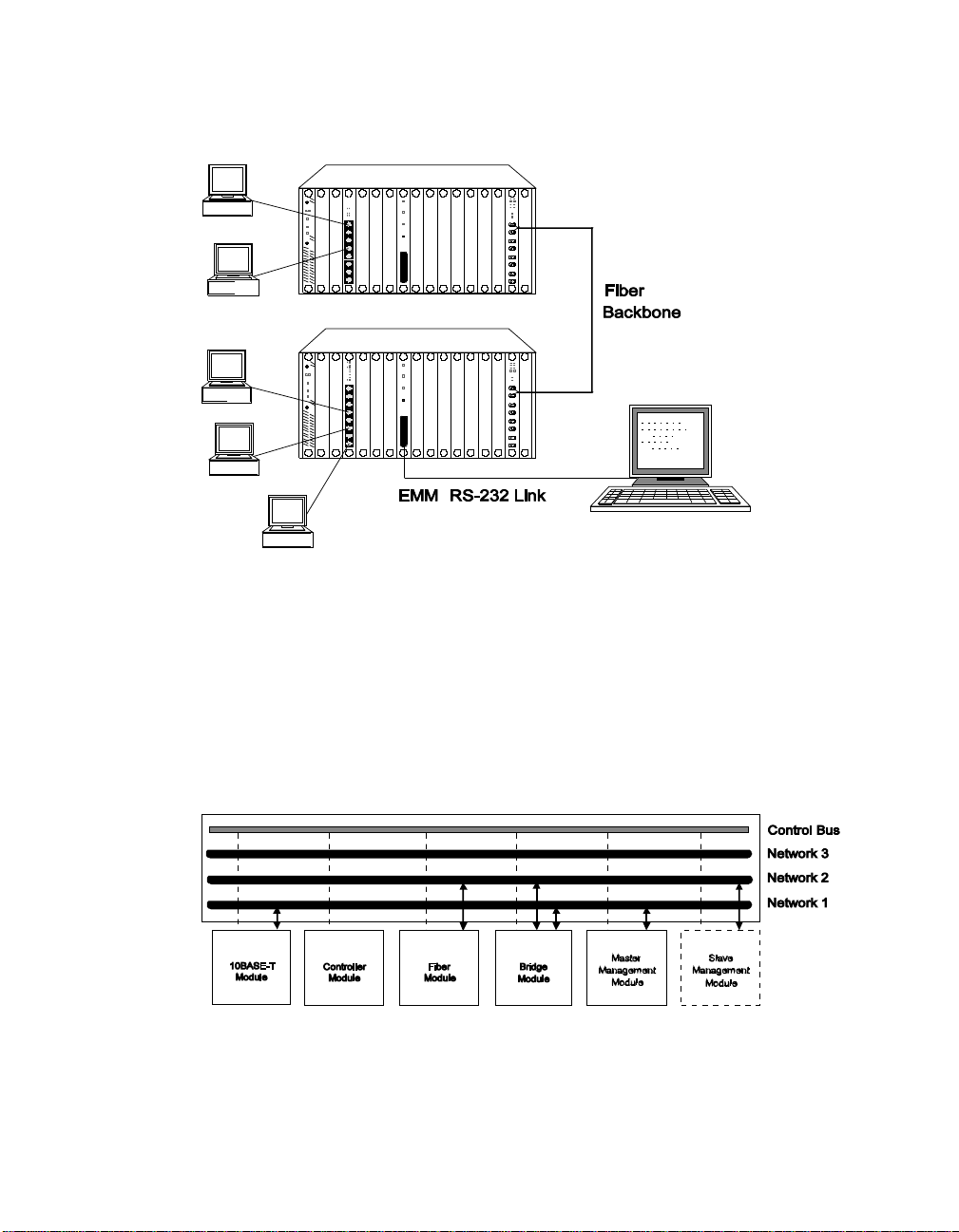
Figure 1-1. EMMs in Network Configuration
Theory of Operation
The EMM can be installed into any slot in the concentrator and
communicates with all other modules in the concentrator via a dedicated
control bus on the concentrator backplane as shown in Figure 1-2.
Figure 1-2. Ethernet Management Module Communication in the
ONline System Concentrator
Introduction 1 - 3
Page 22

Like media modules installed in the ONline System Concentrator , the EMM
is assigned to a network on the concentrator backplane. The configuration
and fault-detection capability of the EMM is protocol-independent an d
enables you to configure all Ethern et modules as well as Token Ring and
FDDI modules. In addition, via the Control Bus, the EMM can configure and
check status on all modules in the concentrator , even if they are assigned to
different networks or are isolated.
If you have modules assigned to different Ether net networks in a
concentrator, you should use multiple EMMs to track statistics on the
individual networks. For configuration management, however, only one
EMM in the concent rator can be the master EMM - all other EM Ms are
considered slaves.
A slave EMM can collect statistics and listen to traffic on the network to
which it is assigned. Since the slave does not have contro l of the Control
Bus, it cannot configure modules or detect faults. The slave module will
take over as master if the master EMM fails, thus providing fault tolerance
for your concentrator management. The administrator assigns a mastership
priority level between 1 and 10 to each EMM.
Since all EMMs are factory set with a priority level 10, the first EMM you
install will automatically become the master for that concentrator . All other
EMMs you install should have their mastership priority changed to a lower
value so as not to conflict with the first EMM.
1 - 4 ONline Ethernet Management Module Installation and Operation Guide
Page 23

Complete ONline Control
When you install an EMM into a concentrator for the first time and it
becomes master , it automatically learns a nd saves the configurations of all
existing modules and their ports. The EMM provides the following features
that maximize security and minimize the risk of losing module and port
configuration settings:
❑ All known modules installed in an ONline System Concentrator after
an EMM has been installed will have all ports disabled to prevent
unapproved connections and will be set to the network setting of
isolated. The one exception is when a module is unknown to the
EMM, in whi ch case it will be configured off its dip switch settings.
❑ If you remove any module from the concentrator and then reinstall it,
or another module of the same type in the original slot, the EMM will
automatically configure it as it was as of the last save.
❑ If you replace an EMM with another EMM, the new EMM
automatically learns the module and port configurations. However,
you will need to configure the new EMM to the proper terminal and
device settings.
ONline Ethernet Management Module Versions
There are three versions of the ONline Ethernet Management Module:
Starter (5101M-MGTS), Basic (5101M-MGTB), and Advanced (5101M-MGTA).
The following paragraphs explain the differences between these three
versions.
The EMM Starter Version
The EMM Starter includes all of the functions of the Basic soft ware, with
the following exception:
❑ Can only manage modules that are assigned to the same network as
the EMM
Introduction 1 - 5
Page 24

The EMM Basic Version
The EMM Basic provides:
❑ Local inband softw are upgrades using TFT P (Trivial File Transfer
Protocol) in mai ntenance mode
❑ SNMP support
❑ Out-of-band software upgrade
❑ Modem support (up to 9600 baud)
❑ Master/slave network managem ent
❑ Automatic statistics reporting
❑ Telnet support for remotely managing the EMM via inband
connection
The EMM Advanced Version
The EMM Advanced includes all of the functions of the Basic software plus
the following features:
❑ Local and remote inband software upgrades using TFTP
❑ Enhanced security through MA C address tracking per port
❑ Cross-module redundancy (ability to set port redundancy using
different modules )
❑ The ability to receive traps from othe r SNMP agents
1 - 6 ONline Ethernet Management Module Installation and Operation Guide
Page 25

Network Management Access
The EMM provides several ways to access networ k management. For
inband management, the EMM provid es built-in SNMP (Simple N et work
Management Protocol) agent, the de facto industry standard for network
management. The agent will let you manage EMMs through SNMP-based
network management solutions.
For out-of-band management, you can connect an ASCII terminal to the
RS-232 port on the module faceplate and manage the EMM using the
command-lin e in terface. You also have the flexibility to use Telnet for
inband management using the same extensive command-line interface.
The EMM also provides the Rem ote_login and Telnet features.
Remote_login is based on the 3Com proprietary proto col, RCP (Remote
Character Protocol). Telnet support is based on a fully compliant TCP /IP
stack.
Network Management Functio ns
The EMM provides management and control capabilities in six major areas:
❑ Configurations - When logged in under the administrator password,
you can configure the EMM, Ethernet network, modules, ports, and
terminal settings.
❑ Fault, Performance, and T raffic Statistics Monitoring - T ypical terminal
management systems only report statistics when you request them.
Y ou can configure the EMM to continuously monitor and report key
statistics by invoking the MONITOR command. The statistics on the
screen are updated periodically to give a snapshot of the network.
❑ Security Control - The EMM provides two important security features
that prevent unauthorized access to devices on the network address-to-port security and a two-level password protection feature.
Introduction 1 - 7
Page 26

❑ SNMP S up po r t - SNMP (Simple Network Management Protocol) is a
protocol defined by the Internet com munity. The EMM acts as an
agent i n a n S NMP managed environment r e sponding t o S NMP
requests and generating SNMP traps.
❑ Inband and Out-of-Band Download - The EMM provides both inband
and out-of-band dow nlo ad features. An inb and download is
performed via TFTP (Trivial File Transfer Protoco l ). The out-o f-band
download is performed using Xmodem software and a connection to
the RS-232 serial port on the front panel of the EMM.
❑ Telnet Support - The T elnet command enables you to log in remotely
to any EMM on the network and manage it from a remote EMM.
You can also manage an EMM from a workstation with Telnet
support.
ONline Backp l ane Architec tu re
The 3Com unique backplane architecture provides you with the power and
flexibility to create multiple Ethernet, Token Ring, FDDI networks in one
ONline System Concentrator. This backplane architecture allows th e
following networks to run in a single ONline System Conc en trator:
❑ three separate Ethernet networ ks and one isolated network
❑ seven backplane Token Ring networks and one isolated network
❑ four FDDI networks and one isolated network
Figure 1-3 illustrates how Ethernet, T oken Ring, and FDDI networks coexist
on the concentrator backplane. Note in Figure 1-3 that Ethernet networks
and paths correspond. That is, Ethernet_1 network is always allocated to
Ethernet path 1, Ethernet_2 network is always allocated to Ethernet path 2,
and Ethernet_3 network is always allocated to Ethernet path 3.
1 - 8 ONline Ethernet Management Module Installation and Operation Guide
Page 27
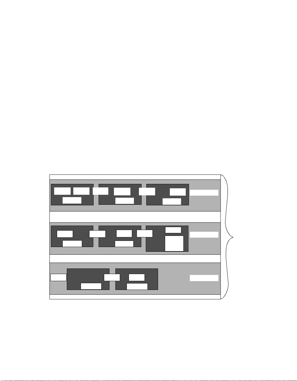
This is not true for Token Ring and FDDI networks and paths. There are 7
available Token Ring networks and 15 Token Ring paths. For FDDI, there
are 4 available FDDI networks and 8 FDDI paths. When you a s sign a
module or port to a network, the master management module dynamically
allocates the best possible path currently available for your configuration.
Following Figure 1-3 are T able 1-1, T able 1-2, and T able 1-3, which provide
reference tables for configuring Ethernet, Token Ring, and FDDI networks
in one concentrator . These tables define which networks paths are
removed when certain network paths are used. Refer to these charts to
determine the n um ber and types of different protocol combinations yo u
can have in one concentrator.
Y ou may want to issue the SHOW NETWORK P A THS command before and
after you configure networks to modules or ports to display which network
paths are in use.
TR1 TR2
FDDI 1
TR7 TR8
FDDI 4
TR13 TR15 TR14
*TR12 overlays part of FDDI 6, but it does not affect the Ethernet 2 path.
TR3
FDDI 17
TR4
FDDI 2
TR9
FDDI 5
FDDI 18
TR5
TR10
TR6
FDDI 3
TR11
FDDI 6
TR12*
Ethernet 1
Ethern et 2
Ethernet 3
Figure 1-3. Tr iChannel Backplane Architecture Assignments
Introduction 1 - 9
ONline
Backplane
Page 28

As shown in T able 1-1, Ethernet_3 is the best Ethernet network selection to
use in a mixed protocol environment because it affects the least amount of
Token Ring and FDDI network paths.
Table 1-1. Ethernet Backplane Combination Reference Chart
Ethern et Paths Token Ring Paths FDDI Paths
Ethernet 1 removes Token Ring 1
Token Ring 2
Token Ring 3
FDDI 1
FDDI 2
FDDI 3
Token Ring 4
Token Ring 5
Token Ring 6
Ethernet 2 removes Token Ring 7
Token Ring 8
Token Ring 9
FDDI 4
FDDI 5
FDDI 6
Token Ring 10
Token Ring 11
Ethernet 3 removes Token Ring 13
Token Ring 14
FDDI 7
FDDI 8
Token Ring 15
Table 1-2. Token Ring Backplane Combination Reference
Chart
Token Ring Paths Ethernet Paths FDDI Paths
Token Ring 1 removes Ethernet 1 FDDI 1
Token Ring 2 removes Ethernet 1 FDDI 1
Token Ring 3 removes Ethernet 1 FDDI 1 and FDDI 2
1 - 10 ONline Ethernet Management Module Installation and Operation Guide
Page 29

Table 1-2. Token Ring Backplane Combination Reference
Chart (Continued)
Token Ring 4 removes Ethernet 1 FDDI 2
Token Ring 5 removes Ethernet 1 FDDI 2 and FDDI 3
Token Ring 6 removes Ethernet 1 FDDI 3
Token Ring 7 removes Ethernet 2 FDDI 4
Token Ring 8 removes Ethernet 2 FDDI 4 and FDDI 5
Token Ring 9 removes Ethernet 2 FDDI 5
Token Ring 10 removes Ethernet 2 FDDI 5 and FDDI 6
T oken Ring 11 removes Ethernet 2 FDDI 6
T oken Ring 12 removes FDDI 6
T oken Ring 13 removes Ethernet 3
T oken Ring 14 removes Ethernet 3 FDDI 8
Token Ring 15 removes Ethernet 3 FDDI 7 and FDDI 8
Table 1-3. FDDI Backplane Combination Reference Chart
FDDI Paths Ethernet Paths Token Ring Paths
FDDI 1 removes Ethernet 1 Token Ring 1
Token Ring 2
Token Ring 3
FDDI 2 removes Ethernet 1 Token Ring 3
Token Ring 4
Token Ring 5
FDDI 3 removes Ethernet 1 Token Ring 5
Token Ring 6
Introduction 1 - 11
Page 30

Table 1-3. FDDI Backplane Combination Reference Chart
FDDI 4 removes Ethernet 2 Token Ring 7
FDDI 5 removes Ethernet 2 Token Ring 8
FDDI 6 removes Ethernet 2 Token Ring 10
FDDI 7 removes Ethernet 3 Token Ring 15
FDDI 8 removes Ethernet 3 Token Ring 14
Where To Go From Here
Token Ring 8
Token Ring 9
Token Ring 10
Token Ring 11
Token Ring 12
Token Ring 15
This chapter presented an overview of the ONline Ethernet Management
Module and its co ntrol capabilities. The next chapter, Unpacking and
Installing the Module, explains how you install the module into your
concentrator.
1 - 12 ONline Ethernet Management Module Installation and Operation Guide
Page 31

Unpacking and
Installing the Module
2
This chapter describes the precautionary, unpacking, and installation
procedures for the ONline Ethernet Man agement Module (EMM). It also
describes the module's front panel LEDs, Reset Button, and RS-232 serial
port connector . After you install the module, follow the steps in Chapter 3
to configure the module for proper operation.
Precautionary Procedures
Electrostatic discharge (ESD) can damage the static-sensitive devices on
circuit boards. T o avoid this kind of damage, use the following precautions
when han dling the EMM:
❑ Do not remove the board from its anti-static shielding bag until you
are ready to insert it into the concentrator.
❑ Use proper grounding techniques when inspecting and installing the
EMM. These techniques include using a foot strap and grounded mat
or wearing a grounded static discharge wrist strap. An alternate
method is to touch a grounded rack or other source of ground before
you handle th e EMM.
Unpacking and Installing the Modul e 2 - 1
Page 32

Unpacking Procedure
Use the following procedure when unpacking the EMM:
1. Verify that the EMM is the correct model by matching the model
number listed on the side of the shipping carton to the model
number you ordered (5101M-MGTB, 5101M-MGTA, or
5101M-MGTS).
Note that the product model number printed on the shipping box
differs from the model number on the product. The model number
on the shipping box contains the prefix ’3C9’.
2. Remove the module, in its anti-static bag, from the shipping carton.
3. Remove the module from the anti-static shielding bag and inspect it
for damage. Always handle the m odule by the faceplate being
careful not to tou ch the components.
4. If the module appears to be damaged, replace it in the anti-static
shielding bag, return it to the shipping carton and contact your local
supplier .
We suggest you keep the shipping carton and anti-static shielding bag in
which your module was shipped in case you later want to repackage the
module for storage or shipment.
We also suggest that you record the serial number of your EMM. A log for
this and other information specific to your modules under the Slot Usage
Chart in Appendix B of the ONline System Co ncentrator Installation and
Operation Guide.
2 - 2 ONline Ethernet Management Module Installation and Operation Guide
Page 33

Installatio n Procedures
For a new installation where you have received a new ONline System
Concentrator and all the modules, the following steps must be performed
prior to installin g the EMM:
❑ Install the concentrator in its location (rack, table, etc.) referring to
the instructions in the ONline System Concentrator Installation and
Operation Guide.
❑ Remove blank panels on the concentrators to expose empty slots for
the Controller Module, EMM, and ONline modules.
❑ Install the Con troller Module and ONlin e m odules into the board
guides at the top and bottom of the slots and slide them into the
concentrator. Make sure the connectors are firmly seated in the
backplane of the co ncentrator.
❑ Fasten the spring-loaded screws on the front panels of the modules
to the concentrator with your fingers (do not overtighten).
❑ Plug the power cord into an outlet and verify that all modules come
up in their default state. Optionally , press the LED Test button on the
Controller Module to ver ify that all LEDs are functional.
Installing the EMM into an existing installation does not require you to
power down the concentrator . The EMM, like all other ONline modules, has
the ability to be “hot swapped,” meaning that you can install the module
into any open slot and remove it with the concentrator in an operating
state. Use the following procedure if you are installing the EMM into an
existing installation.
1. Install the EMM into the board guides at the top and bottom of the
empty slot and slide it into the concentrator as shown in Figure 2-1.
Make sure the connector is firmly seated in the backplane of the
concentrator.
Unpacking and Installing the Modul e 2 - 3
Page 34

Wait for the Status LED and Master Mgt Module LED to light solid
green. At this point the EMM will learn the default module and port
settings for all modules installed in the concentrator.
Figure 2-1. Installing the Ethernet Management Module
2. Fasten the spring-loaded screws on the front panel of the EMM
faceplate to the concentrator with your fingers (do not overtighten).
3. If a terminal (out-of-band) connection is desired, verify that the
terminal meets the factory defaults of the EMM or you will not be
able to communicate with the module. The default EMM settings are:
– 9600 baud
– 8 data bits
– No parity
– 2 stop bits
4. Attach one end of an RS-232 cable to the RS-232 serial port connector
on the front of the EMM . Loop the cable through the concentrator
cable tray (if installed) and attach the other end to the RS-232 serial
port connector on a terminal or personal computer as shown in
Figure 2-2.
2 - 4 ONline Ethernet Management Module Installation and Operation Guide
Page 35

Figure 2-2. Installed EMM Connected to a Terminal
The RS-232 cable can be a maximum of 50 ft. in length. There are several
legal RS-232 cable configurations available depending on your installation.
Refer to Appendix B for more information on the exact RS-232 cable that
you need for your installation.
If you want to connect another type of device to the EMM, you can change
the factory default terminal settings of the EMM as described at the
beginning of Chapter 3.
Verifying Operation
This section explains how to v erify module functionality.
1. The Status LED on the m odule should light and t he Master Mgt
Module LED should light if this is the master EMM (or the only
management module in the con centrator).
Unpacking and Installing the Modul e 2 - 5
Page 36

2. The following message should display on the terminal screen once
the module is installed properly and the RS-232 connection is made:
Ethernet Management Module (v4 .00), Copyright (c) 1993
Chipcom Corporation
The EMM Front Panel
The EMM has three LEDs on the front panel that indicate the status of the
module, one button to reset the module, and one RS-232 serial port
connector used to connect the EMM to a terminal or modem. Figure 2-3
shows the features of the EMM faceplate and T able 2-1 describes the LEDs.
Figure 2-3. Ethernet Management Module Faceplate
2 - 6 ONline Ethernet Management Module Installation and Operation Guide
Page 37

T able 2-1. Interpretation of the Ethernet Management Module LEDs
LED Name Color State Indicates
Status Green Off Power off
On Power on
Blinking Error
Master Mgt
Module
Download in
Progress
Green Off EMM is a slave
On EMM is a master
Yellow Off Not downloading
On Downloading n ew
software to EMM flash
EPROM
Status LED
The Status LED displays a steady green glow to indicate that power is being
provided to the EMM and that the EMM is working proper ly. This LED
blinks when an error occurs during operation or if an error is found when
diagnostics are performed during a reboot. Refer to Chapter 4,
Troubleshootin g, for a description of the error codes.
Master Mgt Module LED
The Master Mgt Module LED displays a steady green glow if this EMM is
the master management module in the concentrator. It also displays a
green glow while a mastership election is in progress and during initial
installation. The LED is off when the EMM is a slave.
Unpacking and Installing the Modul e 2 - 7
Page 38

Download in Progress LED
The Download in Progress LED displays a steady yellow glow when
software is being downloaded to the Flash EPROM on the EMM. See
Chapter 5, Software Download Instructions, for details on downloading
new software.
Note that you need the Firmware Distribution Kit3Com Firmware
Distribution Kit (part number 5000-FDK) to initiate the download of new
software provided in the Update Distribution Kit (part number
5101M-UDKx-x.xx) .
Reset Button
The Reset Button resets the EMM and executes self-test diagnostic routines
(network traffic is not affected). You should press this button only w hen
you suspect problems with the EMM. The Reset Button is recessed to
prevent an accidental reset, yet you can access it with a pen tip or a small
screwdriver.
When the EMM is reset, it will come up under the last saved configuration
parameters. Pushing this button has the same effect as issuing the RESET
DEVICE command with one exception. Pushing the Reset button will cause
any unsaved changes to be lost. Issuing the RESET command on an EMM
after changes have been made but not saved causes a messa ge to display
warning you that unsaved changes exist. The RESET command aborts and
cannot be executed until the SAVE command is issued.
RS-232 Serial Port
The 25-pin (DB-25) RS-232 serial port is a DTE male connector used to
connect the EMM to a terminal or modem so you can enter management
commands and do wnload new software.
2 - 8 ONline Ethernet Management Module Installation and Operation Guide
Page 39

Where to go From Here
This chapter covered installation procedures for installing the EMM into a
concentrator. Also provided were descriptions of the EMM front panel
LEDs, RS-232 port, and the Reset Button. Now you are ready to set up your
terminal for c om m unication wit h the EMM and configure the EMM to
begin managing your Ethernet network as explained in Chapter 3. If you
encountered any problems with installing the module or the operation of
the LEDs, refer to Chapter 4, Troubleshooting.
Unpacking and Installing the Modul e 2 - 9
Page 40

Page 41

3
Startup and
Management Functions
This chapter describes how to configure the EMM once you have
completed the installation procedures outlined in Chapter 2. Included in this
chapter is a quick reference chart for getting started. The remainder of this
chapter is organized into the following sections:
❑ Configuring the Terminal
❑ Config uring the EMM
❑ Configuring SNMP Values
❑ Configuring Modules and Ports
❑ Configuring Address-to-Port Security
❑ Establishing Remote Logins
❑ Monito ring With SHOW Commands
The commands necessary to configure the EMM for operation are provided
in this chapter. The EMM supports similar command conventions and
keystroke functions as other ONline management d ev ices. Refer to th e
ONline Management Commands Guide (17-00403) for complete
information on all ONline management commands and command
conventions.
Startup and Management Functions 3 - 1
Page 42

Quick Reference for Getting Started
Table 3-1 outlines the steps and commands necessary to configure your
EMM. The procedures and command examples are explained further
throughout this chapter. If you are familiar with these instructions, you may
want to use this table as a checklist.
Table 3-1. Quick Reference for Getting Started
Procedure Command
1. Configure your terminal to
default
EMM communication settings
❑ Configure EMM Te rminal
Settings
2. Configure the EMM
❑ Concentrator Configuration
❑ Device Configuration (EMM)
SNMP Configuration SET COMMUNITY
Refer to your terminal v endor's
documentation
SET TERMINAL HANGUP
SET TERMINAL PROMPT
SET TERMINAL TIMEO UT
SET CONCENTRATOR PLATFORM
SET CLOCK
SET DEVICE CONTACT
SET DEVICE DIAGNOSTICS
SET DEVICE LOCA TION
SET DEVICE NAME
SET DEVICE P ASSWORD
SET DEVICE DEFAULT_GATEWAY
SET DEVICE IP_ADDRESS
SET DEVI CE SUB NET_MASK
SETALERT
SET DEVICE TRAP_RECEIVE
(Advanced EMM only)
3 - 2 ONline Ethernet Management Module Installation and Operation Guide
Page 43

Table 3-1. Quick Reference for Getting Started (C ontinued)
Procedure Command
3. Module Configuration SET MODULE
MASTERSHIP_PRIORITY
SET MODU LE NET WORK
SET MODULE RING_SPEED
4. Port Configuration SET PORT
SET PORT MODE
SET SECURITY PORT (Advanced
EMM only)
5. Save All Configuration Values SA VE ALL
6. Monitor the Network and
Device with SHOW commands
❑ Device Information
Module Information
Port Information
Concentrator Information
Counter Statistics
❑ EMM Traffic Statistics
SHOW DEVICE
SHOW MODULE
SHOW PORT
SHOW CONCENTRATOR
SHOW COUNTER MODULE
SHOW COUNTER PORT
SHOW COUNTER NETWORK
Saving and Reverting Config ura tio n Values
When you make configuration changes using the SET c ommand, t hey ar e
effective immediately but are not saved permanently. To s ave comma nds
permanently, use the SA VE command. Only saved values are in effect upon
reset of the EMM or the concentrator. You can issue the SAVE ALL
command to save all current concentrator configuration values previously
established by the SET command for all cat egories. Or you may issue a
specific SAVE command to save the configurations of only one group.
Startup and Management Functions 3 - 3
Page 44

Use the REVERT command to restore the c onfiguration values in effect at
the time of the last save. Any unsaved changes made using th e S ET
command are lost. The REVERT and SAVE commands support the same
configuration groups as defined below.
❑ Alert
❑ All
❑ Community
❑ Concentrator
❑ Device
❑ Security
❑ Module_Port
❑ Te rminal
❑ TFTP
Configuring the Terminal
The terminal that attaches to the serial port on the EMM must be
configured to the same parameter settings as the EMM so the terminal and
EMM can communicate. These settings include baud rate, data bits, parity ,
and stop bits. Initially , the terminal settings must match the factory default
settings of the EMM as specified in Table 3-2 . Consult the user's guide
shipped with your computer terminal for instructions on how to set these
values
3 - 4 ONline Ethernet Management Module Installation and Operation Guide
Page 45

.
Table 3-2. EMM Terminal Parameter Options and Factory Defaults
Parameter Options Factory Defa ult
Baud 300, 1200, 2400, 4800, 9600 9600
Data_bits 7 or 8 8
Parity odd, even, or none none
Stop_bits 1 or 2 2
Once you have configured your terminal to match the factory defaults of
the EMM, press [ENTER] and the following greeting is displayed:
Ethernet Management Module (v4.00) Copyri ght (c) 1993 Chipcom Corporation
Press [ENTER] again and the EMM prompts you for a password. Enter the
password and then press [ENTER] (the default password is a null string).
The following greeting and the default management prompt is displayed:
Welcome to system administrator service on ONline.
ONline>
You are now logged in as the administrator with full access to all
commands. Once terminal setti ngs are complete, yo u can configure the
ONline System Concentrator , the newly installed EMM, and all other ONline
modules residing in the concentrator.
When you are done using the EMM, save all changes, and then log out of
the system using the LOGOUT co mmand. Provided you have saved all
changes before issuing this command, you are logged out of the system
and the following message displays:
ONline> logout [ENTER]
Bye
Startup and Management Functions 3 - 5
Page 46

If you have made configuration changes and you have not saved those
changes, the LOGOUT command prom pts you as follows:
ONline> logout [ENTER]
WARNING: Save unsaved changes before logout.
You must either SAVE or REVERT any changes you made to the system
before you can successfully log out. Re-issue the LOGOUT command to log
out of the system once you have saved or reverted.
Optional Termina l Settings
The EMM provides three additional terminal management commands that
allow you to customize your term inal connection:
❑ terminal hangup
❑ terminal prompt
❑ terminal timeout v alue
These terminal settings are discussed in the following paragraphs. Also
included in this section is the procedure to change the terminal's setting if
you need to connect another device to the EMM that runs at a slower baud
rate or different parity or data bits values than the factory settings.
Setting Terminal Hangup
If you use a modem connection to the EMM, you may want to use the SET
TERMINAL HANGUP command to specify that the modem automatically
hang up the connection to the terminal when you log out of the EMM. The
factory default is disable, which means the modem will not automatically
hang up when y ou log out of the connection. If you fail to hang up the
modem connection, an unautho rized user may pick up the last lo gin
session.
Use the SET TERMINAL HANGUP command as shown to automatically
hang up the modem connection once you log out of the EMM:
ONline> set terminal hangup enable [ENTER]
3 - 6 ONline Ethernet Management Module Installation and Operation Guide
Page 47

Setting Terminal Prompt
It is a good idea to customize the management prompt for each EMM. This
will remind you of the EMM to which you are connected in the case where
you are logged into a remote EMM. The d efault management prompt is
“ONline>” for all Hems. Use the SET TERMINAL PROMPT command as
shown to customize your management prompt. 3Com recommends that
you use the same identification to specify the terminal prompt and device
name for your EMM.
ONline> set terminal prompt NEW PROMPT> [ENTER]
Setting Terminal Timeout
For optimum security, you should set the terminal timeout value to specify
the amount o f time you want yo ur terminal to remain active during the
absence of any keyboard activity. This feature is useful for keeping
unauthorized users off the system if you leave your terminal without
logging off. Once timeout has been set, the terminal will automatically log
you off the system if there is no terminal (keyboard) activity for the period
of time you have specified.
The default timeout value is 0, which means that no timeout has been set you will never be logged off automatically. Use the SET TERMINAL
TIMEOUT command as shown to set the timeou t period. Note that the
value specified is in minutes.
ONline> set terminal timeout 10 [ENTER]
Configuring the EMM
This section describes the commands necessary for startup and
management of your concentrator and EMM. You need to define the
following setting s for your EMM :
❑ Passwords
❑ EMM Name
Startup and Management Functions 3 - 7
Page 48

❑ Diagnostics
❑ Contact Nam e and Location
Use the following command to set the EMM' s internal clock .
ONline> set clock 5:53 93/03/6 Saturday [ENTER]
Use the following command to define the concentrator platform for your
EMM.
ONline> set concentrator platform {5006C} [ENTER]
{5017C}
{5006C-FT}
Note: Use the 5006C designation for all 6-slot concentrators.
Figure 3-1, Figure 3-2, and Figure 3-3 show an ONline 17-Slot System
Concentrator, an ONline 6-Slot System Concentrator , and an ONline 6-Slot
System Concentrator with Integrated Controller , respectively . As the names
imply , there are 17 available slots (numbered from left to right) on the large
concentrator and 6 slots (numbered top to bottom) on the smaller
concentrators.
SLOT
2 3 4 5 6 7
1
8910 11
12 13 141516 17
Figure 3-1. The 17-Slot ONline System Concentrator
3 - 8 ONline Ethernet Management Module Installation and Operation Guide
Page 49

1
2
3
4
5
6
Figure 3-2. The 6-Slot ONline System Concentrator
1
2
3
4
5
6
Figure 3-3. The 6-Slot ONlin e System Concentrator w ith Integrated
Controller
Setting Device Password
The EMM provides two levels of password protection to protect against
unauthorized access to the EMM console and possible network tampering.
❑ Administrator. The administrator password provide s acce ss to all
EMM commands.
❑ User. The user password allows limited access to EMM commands
enabling status and configuration displays only.
Startup and Management Functions 3 - 9
Page 50

Both the administrator and the user password can be a maximum of 15
characters in length. Note that you must enter a password within 10
seconds following the display of the Password: prompt, or the terminal will
display “Timeout.” If this happen s, press [CTRL] [R] to redisplay the SET
DEVICE P ASSWORD command. The new passwords you set go into effect
immediately , but you must issue the SAVE DEVICE (or SAVE ALL) command
to save the new passwords.
Establishing the Administrator Password
Use the following command to establish the administrator password.
ONline> set device password administrator [ENTER]
Enter cu rrent administrator password: {old password} [ENTER]
New pass word: {new password} [ENTER]
Verify: {new password} [ENTER]
Note: For security purposes, the values you enter in the password
fields are not displayed on the screen.
Y ou do not need to use the new administrator password until the next time
you log in to the EMM.
As EMM administrator, you can conf igure the following:
❑ Device - This includes naming the EMM, establishing passwords,
setting mastership priority , setting SNMP Values, as well as providing
location and contact information.
❑ Modules - The EMM can assign each module in the ONline System
Concentrator to one of the available networ ks or i solate it (not
connect that module to any network). Reconfiguration of network
assignments can be done at any time, witho ut removing a module
from the concentrator or disrupting other configuration settings. If a
module is removed from the concentrator slot and replaced with the
same module ty pe in the same slot, the new module will be
configured to the settings of the previous module installed in that
slot.
3 - 10 ONline Ethernet Management Module Installation and Operation Guide
Page 51

❑ Ports - The EMM can assign each port on a per-port switching ONline
module to one of the available networks. Reconfiguration of network
assignments can be done at any time, without removing the module
from the concentrator or disrupting other configuration settings.
❑ Override Control - The EMM can overr ide all ONline module d ip
switch set ting s .
❑ Terminal - EMM terminal configuration values can be modified to
meet your particular application requirements.
❑ Security - The EMM address-to-port security feature enables you to
assign a maximum of four MAC addresses to a port. Whenever a
device assignment is changed, the EMM is alerted to the change in
MAC Address, sends a trap to the designated workstation, and
automatically disables that port.
❑ Fault Tolerance - The EMM can assign the ports of some modules
(e.g., Fiber Module, 10BASE-T Module) as redundant pairs in order to
provide fault-toleran t links between concentrators or between
devices (when using Fault-To lerant Transceivers).
Establishing the User Password
Use the following command to establish a user p assword. Note that you
must be logged in as administrator to change the user password. The
default user password is [ENTER].
ONline> set device passw ord user [ENTER]
Enter current administrator password: {administra tor password} [ENTER]
New passwo rd: {new use r p assword} [ENTER]
Verify: {new use r password} [ENTER]
Startup and Management Functions 3 - 11
Page 52

Assigning an EMM Name
To make identification of your EMMs easier, 3Com recommends that you
assign a unique name to each EMM. Y ou can then use this name instead of
the IP address or MAC address to refer to a particular EMM. Use the SET
DEVI CE NAME co mmand a s shown t o ass ign a un ique na me to yo ur EMM.
The EMM name can be a maximum of 31 characters.
ONline> set device name EMM3 [ENTER]
3Com recommen ds that you use the same identification to specify the
terminal prompt an d the device name for your EMM.
Setting Device Diagnostics
When the EMM is reset (or rebooted) using the factory default settings, the
module performs a full diagnostic check of itself and t hen sets all the
modules to the approp riate settings. You have the option to disable the
diagnostics if you want the EMM to boot up faster. Use the SET DEVICE
DIAGNOSTICS command as shown to bypass the diagnostics.
ONline> set device diagnostics disable [ENTER]
Assigning a Contact Name and Location
The EMM enables you to enter the name of an appropriate service contact
and the concentrator location. Use the SET DEVICE LOCATION and SET
DEVICE CONT ACT commands as shown to identify the location of the EMM
and the name of the person responsible for EMM operation. These
commands allow you to enter one line of free format text up to 78
alphanumeric characters in length. Note that you must enter the line of text
within 15 seconds of receiving the prompt or the com m and will timeout.
ONline> set device location [ENTER]
ONline> set device contact [ENTER]
3 - 12 ONline Ethernet Management Module Installation and Operation Guide
Page 53

Configuring SNMP Values
SNMP (Simple Network Management Protocol) is a protocol defined by the
Internet co m munity. All TCP/IP-ty pe traffic is encapsulated in Ethernet
frames. The EMM supports SNMP by responding to SNMP requests and
generating SNMP traps. An EMM acts as an agent in an SNMP- managed
environment, enabling you to configure your EMM and all modules in the
concentrator through SNMP. It has a community table that can contain up
to 10 IP addresses.
An IP Address entry in a community table may have one of the following
attributes assigned:
– read-only allows the specified IP address to re ad SNMP
variables via the SNMP GET command
– read-write allows the specified IP address to read and
write SNMP variables via the SNMP GET and SNMP SET
commands, respectively
– trap sends a trap to the specified IP address when an
SNMP variable is changed
– read-trap allows the specified IP address to read SNMP
variables and receive traps
– all (rea d-write, and trap) allows the specified IP address
to read SNMP variables, change the variables via the SNMP
SET command and receive traps wh enever an SNMP
variable is changed.
– oldtrap access means that the IP Address you specify will
receive alerts from the EMM based on the 3Com MIB I.
– read_oldtrap access means that the IP Address you
specify can display information about the EMM and it will
receive alerts based on the 3Com MIB I.
– oldall access means that the IP Address you specify has
read_write and trap access to the EMM based on the
3Com MIB I.
Startup and Management Functions 3 - 13
Page 54

Note: When you use the IP Address entry of all, you cannot use
trap, read_trap, or all access.
The three “old” trap options should be used when sending traps to
workstations using the 3Com MIB I variables. All the non-”old" trap options
should be used when sending traps to workstations using the 3Com MIB II
variables.
An EMM sends alarms to those IP addresses in the community table having
either trap, read-trap, or all attributes. The EMM and all modules in the
concentrator can be configured via SNMP from stations having IP addresses
with either read-write or all attributes. Finally, the EMM can be monitored
from stations having IP addresses with read-only , read-write, read-trap, or
all attributes.
An EMM can receive SNMP alarm s from SNMP devices on the net work
(including its elf) once the EMM's IP address and accompanying attributes
have been added to the community table of the SNMP device generating
the alarms, and the SET ALERT feature is enabled.
For example, if a major fault co ndition causes a port to be disabled, an
SNMP alarm is generated and displays to the terminal or workstation. This
feature enables you to analyze network information simply by accessing a
single EMM instead of having to be at the network management
workstation.
If you plan to manage your concentrator through an SNMP workstation,
you must set the following attributes for th e EMM:
❑ IP Address
❑ Community Table
❑ Alerts
❑ Subnetwork Mask
❑ Trap Receive
❑ Default Gateway
3 - 14 ONline Ethernet Management Module Installation and Operation Guide
Page 55

Assigning IP Addresses
T o run SNMP properly , every device on your network must have a unique IP
address. Use the SET DEVICE IP_ADDRESS command as shown to assign an
IP address for the EMM on network 1. Note that you can set separate IP
addresses for each of the ind ividual networks on the concentrator
backplane.
ONline> set device ip_address 195.36.58.27 network_1 [ENTER]
Creating a Community Table
The community table defines which SNMP stations on the network can
access information from the EMM and which station(s) will receive a trap
from the EMM when the EMM detects an error . For example, the following
command adds a community name of NCS with IP Address 195.36.58.217
to have read_write access:
ONline> set community NCS 195.36.58.217 read_write [ENTER]
Note that community entry names are case-sensitive. For example NCS and
ncs are different community names. Use the SHOW COMMU NI TY
command to view existing community entries.
Configuring the Alert Setting
The SET ALERT command enables or disables the feature used to send an
alert to the management workstation. The following command enables the
alert feature. Therefore, when a configuration chan ge i s mad e to the
concentrator via SNMP, an alert will be sent to the management
workstation.
ONline> set alert change enable [ENTER]
Refer to the SET ALERT command in the ONline Management Commands
Guide for information on the different types of alerts available through this
command.
Startup and Management Functions 3 - 15
Page 56

Setting a Subnetwork Mask
The subnetwork mask is specific to each type of Internet class. Generally,
the subnetwork mask is a group of common characters appearing on the
left side of an IP Address (called the Network ID), while the host address is
the group of unique characters appearing on the right side of an IP
Address. For example, to set the subnetwork mask for a class C address
without subnetworks, enter the following command:
ONline> set device subnet_mask FF.FF.FF.00 all [ENTER]
The subnetwork mask for a class B device without subnetworks would be
set using the following command:
ONline> set device subnet_mask FF.FF.0.0 ne twork_1 [ENTER]
Note that you can set separate subnetwork masks for each of the individual
networks on the co ncentrator backplane, or the same subnetwor k mask
for all of the networks on the concentrator backplane.
Defining the Default Gateway
The default gateway is the IP Address of the gateway that receives and
forwards packets whose addresses are unknown to the local network. The
default gateway is useful when sending EMM alert packets to a
management workstation on a different network. For example, the
following command specifies that the gateway with address 195.3.6.58 is
to become the default gateway:
ONline> set device default_gateway 195.3.6.58 all [ENTER]
Note that you can set separate default gateways for each of the individual
networks on the concentrator backplane, or the same default gateway for
all of the networks on t he concentrator backplane.
3 - 16 ONline Ethernet Management Module Installation and Operation Guide
Page 57

Enabling Trap Receiv e
The Advanced version of EMM software provides you wi th the ability to set
the EMM as a trap receiver . As a trap r eceiver , the EMM receives traps from
other SNMP devices that have the EMM's IP address in their community
table.
Use the following command to enable an EMM to function as the trap
receiver for other SNMP devices on the network.
ONline> set device trap_receive enable [ENTER]
Note: You must add the EMM's IP Address to a device's
community table in order for that device to be able to send
traps to the EMM.
Configuring Modules and Ports
This section describes how to assign the EMM and media modules to an
Ethernet network and how to configu re ports. Also discussed is the
importance of settin g the appropriate m astership priority l evel for your
EMM. Appendix B of the ONline System Concentrator Installation and
Operation Guide provides a chart to r ecord the values you se t for modules
in your concentrator.
Assigning Module Networks
Modules assigned to the same network form a segment. Modules assigned
to different networks cannot communicate with each other unless the
networks are bridged. All ONline modules, except the Fau lt-Tolerant
Controller Module and the Token Ring MAU Module can be assigned to a
network. The Controller Module does not require a network assignment as
it only connects to th e control bus and the Token Ring MAU M odule is
connected through its trunk or Ring In/Ring Out ports.
Startup and Management Functions 3 - 17
Page 58

If you isolate a module, the isol ated module cannot send or receive any
traffic from other modules in the concentrator. Initially, all ONline modules
are factory-set to network 1, but will come up isolated if a managem e nt
module is installed in the concentrator.
Use the following command to assign the Ethernet module in slot 7 to
network ethernet_1:
ONline> set module 7 network ethernet_1 [ENTER]
Assigning Module Master ship Priority
All ONline management modules are shipped from the factory with a
mastership priority level of 10. Ten is the highest priority. When multiple
management modules reside in the same concentrator, the SET MODULE
MASTERSHIP_PRIORITY command enables you to establish one of the
modules as master management module and all other modules as slaves.
An EMM master manages the network to which it is assigned, controls all
configuration, and supplies all fault-detection capabilities for the ent ire
concentrator. A slave management module can only listen to its assigned
network's activity. Both master and slaves can collect statistics on only one
network at a time .
The first EMM you place in a concentrator should main tain the default
mastership priority level of 10. Once installed, the priority levels of all other
EMMs should be changed to a different mastership priority l evel.
Use the following command to set the EMM in slot 3 to mastership priority
10:
ONline> set module 3 mastership_priority 10 [ENTER]
Once mastership priorities are assigned, you must issue the RESET
MASTERSHIP command to initiate an election. During an election, the
management module with the highest assigned mastership priority
becomes the master . The new mastership setting is in effect immediately,
but you must use the SAVE MODULE_PORT command t o save this priority
permanently.
3 - 18 ONline Ethernet Management Module Installation and Operation Guide
Page 59

Note: When you power up a concentrator in which more than
one management modules is set to priority level 10, one
management module is randomly chosen as master. 3Com
recommends that you assign priority level 10 to only one
management m odule in the concentrator.
Setting Port Mode
Use the SET PORT command to enable port 1 on the module in slot 3:
ONline> set port 3.1 mode enable [ENTER]
Setting Port Network
Use the SET PORT NETWORK command to assign a port to a specific
network. This command applies to 3Com modules (e.g., the ONline
Ethernet Bridge Module) where individual ports are networ k-selectable.
This example assigns port 1 on the module in slot 7 to network ethernet_3.
ONline > set por t 7.1 netwo rk eth erne t_3 [EN TER]
Setting Redundant Ports
Use the SET PORT MODE REDUNDANT command as shown to set
redundancy between port 1 on the module in slot 5 to port 2 on t he
module in slot 7.
ONlin e> set port 5.1 mode redund ant 7.2 [ ENTER]
Startup and Management Functions 3 - 19
Page 60

Configuring Address-to-Port Security
The Advanced EMM provides address-to-port security which enables you to
assign a maximum of four MAC Addresses to individual ports in y our
network. This allows the EMM to detect a change in the MAC Address of a
station connected to a port whenever a different device is connected to
that port. When a master EMM detects such an address change, it disables
the port to preserve network security, and sends a trap to all stations with
trap or all access in its community tab le.
A slave EMM (Advanced) can also detect a change in a port's MAC address.
The slave EMM will send a trap to all stations in its community table,
however, it cannot disable the port. Once you are alerted to the trap
(displayed on the EMM console or workstation), you must issue the SET
PORT MODE DISABLE command to disable the port.
Once you have determined and rectified the in truding station, you must
issue the SET PORT MODE ENABLE command to re-enable the port.
Note: All versions of the EMM (i.e., Starter, Basic, Advanced) are
capable of managing the ONline 10BASE-T Security Module.
However , only the Advanced EMM supports management
security features. Therefore, when you use a Starter or
Basic EMM to issue a security command using the 'all'
option, the EMM scans the concentrator for Security
Modules and initiates the command on Security modules
only.
When you use an Advanced EMM to issue a security command
using the 'all' option, the EMM will initiate the command on all
Ethernet modules that support security.
3 - 20 ONline Ethernet Management Module Installation and Operation Guide
Page 61

To implement port security , assign a MAC Address to a given port before
you enable the security feature for that port.
Issue the following command to assign a MAC A ddress to port 3 on the
module in slot 6:
ONline> set security port 6.3 mac_address 08-00-8f-12 -c0-09 [ENTER ]
Use the following command to enable the security feature for all ports on
the module in slot 7. Prior to enabling the security feature, you must already
have assigned a MAC Address to each port:
ONline> set security port 7.all mode enable [ENTER]
Use the SHOW SECURITY PORT command to display the MAC address and
security setting for a specific module and port, for all ports, or for all port's
of a specific module.
The following example displays security settings for all of the ports on the
Fiber Modul e in slot 16.
ONline> show security port 3.all verbose [ENTER]
Security Display for Module 5104M- FB in Slot 3:
Port
16.01 ENABLED 08-00-8f-1b-0b-ad ETHERNET_1
16.02 ENABLED 08-00-8f-3c-c6-1e ETHERNET_1
16.03 DISABLED 08-00-8f-00-0e-c6 ETHERNET_1
16.04 DISABLED 08-00-8f-00-0e-2e ETHERNET_1
Mode MAC Addresses Genera l Information
Managing Secur ity with EMM Master and Sla ves
When managing security in Ethernet modules (other than the 5112M-TPLS
Security Module), 3Com recommends that all security configuration
changes to an Ethernet module only be issued through the EMM (master or
slave) that is managing the network to which that module is assigned. This
eliminates the possibility of having two different security configurations for
one module stored in two EMMs. (This consideration does not apply to the
Security Module becau se only a master EMM is capable of managing it.)
Startup and Management Functions 3 - 21
Page 62

By followin g this guideline, you will avoid having secu rity configurati on
information restored incorrectly in the unlikely event both the master EMM
and concentrator power fail concurrently, with at least one slave EMM in
the concentrator . In this scenario, the slave will power up and become
master, and will configure a module's security settings according to the
information stored in its memory. This information may be different than
the previous master EMM's information if you made security configuration
changes using the slave rather than the master.
Establishin g Remo te Logins
The TELNET command and the REMOTE_LOGIN command enable you to
log in remotely to any EMM on the network, and to manage the network
remotely (from a terminal attached to a remote EMM, or from a
workstation with Telnet support). You can manage an EMM across any
number of bridges and routers.
You must be lo gged into the local concentrator before you can issue the
TELNET command or the REMOTE_LO GIN command. Once you are
connected to the remote EMM, you must enter that EMM's password.
Then, all the commands you issue are for that EMM and are identical to
those issued under a local login.
As shown in Figure 3-2, once you are connected to the EMM in
Concentrator C, you can remotely log in and manage the EMMs in
Concentrators A and B.
3 - 22 ONline Ethernet Management Module Installation and Operation Guide
Page 63

Concentrator A
EMM IP Address 1.2.3.4
Concentrator B
Concentrator C
Dial-in
Modem
RS-232 Link
Figure 3-4. Sample Remote Connection
Dial-in
Modem
Use the TELNET command and specify the IP Address of the re mote device
to which you want to connect.
ONline> telnet 127.3.6.58 [ENTER]
Note that you are only allowed on e Telnet login session per EMM.
Therefore, it is not possible to be logged into Concentrator A and
Concentrator B (in Figure 3-2) simultaneously.
Use the REMOTE_LOGIN command and specify the EMM name, IP address
or MAC address of the remote EMM to which you want to connect.
ONline> remote_login 127.3.6.58 [ENTER]
Refer to the ONline Management Commands Guide for a complete
description of the TELNET and REMOTE_LOGIN commands.
Startup and Management Functions 3 - 23
Page 64

Logging Out From a Remote Session
When you no longer need to be connected to a remote device, enter the
LOGOUT command. This command disconnects the remote connection and
reconnects the session with the local EMM. Once this is done, the local
management prompt returns to the local screen.
If TIMEOUT has been set for the remote EMM and the time runs out, you
will be logged out of the remote EMM and returned to the local EMM.
Unsaved changes are still in effect, but they will be lost if the EMM is reset.
To save these changes, re-establish connection to the EMM and issue the
SAVE comman d.
Monitoring With SHOW Commands
The EMM enables you to display device (EMM), module, port, and
concentrator configuration settings using the SHOW commands.
Showing Device Information
Use the SHOW DEVIC E command to view the current EMM information.
ONline> show device [ENTER]
3Com Advanced Ethernet Management Module (5101M-MGTA)
v4.00.0 AgentOS SNMP
Name: ONline
Location: Wiring Closet 3
For assi stance contact: Network Administrator
Boot EPROM Version: v3.2 Serial
Number: 850836 Restarts: 7
Flash EPROM Version: v4.00-A Service Date: 93/06/16
Network
1 * 151.104.002.205 FF.FF.00.00 151.104.002.001
2 151.104.006.214 FF.FF.00.00 151.104.006.001
3 151.104.006.214 FF.FF.00.00 151.104.006.001
IP Address Subnet Mask De fault Ga tew ay
3 - 24 ONline Ethernet Management Module Installation and Operation Guide
Page 65

MAC Address: 08-00-8F-10-6B-B3
Dip Configuration: DISABLED Diagnostics: ENABLED
Trap Re ceive: ENABLED
Showing Module Information
Use the SHOW MODULE ALL command to view information about all of
the module s currently installed in the concentrator:
ONline > show module all [ENTER ]
Slot
01 5000M-RCTL xx N/A Active Red undant Control ler
03 5104M-FBP xx ETHERNET_1
05 5108M-TP xx ISOLATED
*15 5101M-MGT xx ETHERNET_1 Master Management Module
In this example, slot 1 contains the Controller Modu le, slot 3 co ntains a
Fiber Module on network 1, slot 5 contains a 10BASE-T Module that is
isolated from the backplane networks, and slot 15 contains a master EMM
on network 1.
For additional information about a module, issue the SHOW MODULE
VERBOSE command. The example belo w displays more detailed
information about the EMM in slo t 15.
ONline> show module 15 verbose [ENTER]
Slot
*15 5101M-MGT xx ETHERNET_1 Master Management Module
Module Version Network General Information
Module Version Net work Genera l I nf orm a ti on
5101M- MGT : ONline Ethern et Ma na g eme nt Module
Master shi p_ p rio ri t y: 10
Statio n A ddr es s : 08-00-8F-10- 6B - B3
Startup and Management Functions 3 - 25
Page 66

Showing Port Information
The EMM enables you to display the status of all module ports. Use the
SHOW PORT command to display the mode and status of one port or all
ports. Use the VERBOSE option as shown to display detailed information
about a specific port.
ONline > show port 16.1 verbose [ENTER]
Port Display for Module 5104M-FBP:
Port
16.01 DISABLED LINK FAILURE ETHERNET_1
Port Alert Filter: DISABLED
Port Connector: FIBER
Mode Dip Setting: ENABLED
Issue the SHOW PORT ALL command to display information for all ports on
a four-port Fiber Module instal led in slot 3.
ONline> show port 3.all [ENTER]
Port Display for Module 5104M-FBP:
Port
03.01 ENABLED OKAY ETHERNET_3
03.02 ENABLED LINK FAILURE ETHERNET_3 Port is down
03.03 ENABLED OKAY ETHERNET_3
03.04 ENABLED OKAY ETHERNET_3
Mode Status Network General Information
Mode Status Network General In formation
Showing Concentrator Information
The SHOW CONC ENTRATOR command reports the status of the primary
and backup power supplies and temperature status for that concentrator.
ONline> show concentrator [ENTER]
Concentrator Information:
Concentrator Type: 5017C
Primary power supply status: NORMAL
Backup power supply status: NORMAL
Temperature sensor status: NORMAL
3 - 26 ONline Ethernet Management Module Installation and Operation Guide
Page 67

Showing Counter Statistics
Once the EMM is assigned to a network, it continuously records and
updates traffic and error statistics on all Ethernet stations, ports, and the
network to which it is assigned. The SHOW COUNTER command can be
issued for a module, port, or network.
Issue the SHOW COUNTER command to display the total traffic and err or
statistics recorded since either a module or port was first installed, or since
the last time the counters were cleared (using the CLEAR COUNTER
command).
Use the SHOW COUNTER MODULE command as shown to display traffic
and error statistics for the mod ule in slot 3.
ONline > show counter module 3 [ENTER]
Non-zero counters for network ETHERNET_1 on 09 Aug 93:
Slot Frames Bcast CRC Err AlignErr Collisions
Time Octets Mcast TooLongErr Remote
–––––– ––––––––––––––––––––––––––––––––––––––––––––––––––––––––––
3 1500 500 0 162 3
18:17: 12 9000 1325 0
Use the SHOW COUNTER PORT comm and as shown t o report tra ffic and
error statistics for the ports on m odule 3.
ONline > show counter port 3.all [ENTER]
Non-zero counters for network ETHERNET_1 on 09 Aug 93:
Slot.P ort Frames Bcast CRC Err AlignErr Collisions
Time Octets Mcast TooLongErr Remote
LastSourceAddr Changes LastErrorAddr
––––––––––––––––––––––––––––––––––––––––––––––––––––––––––––––––
3.1 1200 350 0 12 1
18:16:28 8600 125 0
08-34-8e-41-20-50 13 08-12-03-3e-74-06
3.2 150 75 0 75 1
18:16:28 200 600 0
08-04-23-15-10-67 4 08-40-65-8e-30-32
3.3 150 75 0 75 1
18:16:28 200 600 0
08-75-34-05-30-8d 7 08-35-46-75-60-32
Startup and Management Functions 3 - 27
Page 68

Use the SHOW COUNT E R NETWORK command as shown to report traffic
and error statistics for the network to which the EMM i s assigned .
ONline > show counter network [ENTER]
Non-zero counters for network ETHERNET_1 on 9 Aug 93:
Network Frames Bcast CRC Err AlignErr Collisions
Time Octets Mcast TooLongErr Remote/Local
–––––– ––––––––––––––––––––––––––––––––––––––––––––––––––––––––
ETHERNET_1 928 21 0 1 16502
13:24:47 74129 129 0 51
Using the MONITOR Command
The EMM can be set to continuously monitor and report key network
statistics by invoking the MONITOR command. The statistics on the screen
are updated periodically to give you a snapshot of the network activity . The
information displayed by the MO NITOR command is current, rather than
cumulative.
Use the MONITOR command to periodically report current net work
statistics for the EMM (the frequency of reporting is determined by the
time, expressed in minutes, that you request). Note that the MON ITO R
command report s the s am e information as the SHO W COUNTER
NETWORK comma nd except that the system reports on ly on the events
occurring for the time you specify.
Where To Go From Here
This chapter described how to configure your EMM to suit your specific
network requirements, as well as how to display information about your
EMM, ONline modules and ports, and the ONline System Concentrator in
which the modules are installed. The next chapter, Troubling, provides
troubleshooting suggestions for isolating and correcting problems that may
arise during the installation proce ss and normal operations of the ONline
Ethernet Managem ent Module.
3 - 28 ONline Ethernet Management Module Installation and Operation Guide
Page 69

4
Troubleshooting
This chapter provides help in isolating and correcting problem s that may
arise during the installation process and normal operations of the ONline
Ethernet Management Module (EMM). It is divided into th e following
sections:
❑ Applying Power
❑ EMM and Terminal Interface
❑ EMM Trap and Error Messages
❑ Technical Assistance
❑ EMM Network Impact
Applying Power
Under normal conditions, when you install the EMM, the Status LED and
the Mastership LED turns on. The Mastership LED remains on if the EMM is
elected master . T able 4-1 lists some of the common problems that may arise
when installing your EMM, and th eir solutions
Troubleshooting 4 - 1
Page 70

.
Table 4-1. Applying Power Suggestions
Problem Troubleshooting Suggestions
Power is on, but the Status LED
does not light.
The Status LED is blinking,
failing diagnostics.
Press the LED check button on the
Controller Module to verify that the
LED is not burned out. All the LEDs
should light.
Verify that the EMM is installed
correctly by following the installation
instructions in Chapter 2.
Try the EMM in another slot in the
concentrator.
Press the reset button on the EMM.
If the LED still does not light, the
software on the Flash EPROM may be
corrupted, Try downloading a new
copy of the software as described in
Chapter 5.
If downloading software does not
solve the problem, call your supplier
for assistance.
Try the suggestions for th e previous
problem.
4 - 2 ONline Ethernet Management Module Installation and Operation Guide
Page 71

Table 4-1. Applying Power Suggestions (Continued)
Problem Troubleshooting Suggestions
Master Mgt LED not lit. Check if another EMM in the
EMM and Terminal Interface
Follow the directions in Chapter 2 for attaching your terminal to the EMM
using the RS-232 serial port connector . Table 4-2 lists some common
problems that may occur when trying to get the EMM to communicate
with the terminal.
concentrator is master.
If there is only one EMM in the
concentrator, verify that it is set to a
mastership priority of 10 (using the
SHOW MODULE {slot} VERBO SE
command) and then press the reset
button on the EMM.
Try the suggestions for th e previous
problem.
Table 4-2. EMM Terminal Interface Suggestions
Problem Troubleshooting Suggestions
Nothing appears on the screen. Make sure the R S-232 cable meets the
specifications detailed in Appendix B.
Make sure the RS-232 cable is
securely connected to both d evices.
See Chapter 2 for installation
instructions.
Verify that the baud rates match for
the terminal and the EMM.
Troubleshooting 4 - 3
Page 72

Table 4-2. EMM Terminal Interface Suggestions (Contin ued)
Problem Troubleshooting Suggestions
Characters appear on the
screen, but are garbled.
The SET command doesn't
work.
Abbreviated input is used and
pressing [SPACE] does not
complete the input.
Random characters are lost. Set the flow control on the terminal
Characters are lost when
connected to the EMM through
a modem.
The management prompt on
the screen is not as you set it.
Power up (switchover) brings up
a different configuration than
the one last set.
Verify that the EMM and the terminal
settings match for baud, data bits,
stop bits, and parity . These values are
explained in Chapters 3.
Make sure you are logged in as the
Administrator and that you are
connected to the master EMM.
Enter enough characters for the EMM
to distinguish between d ifferent
commands and options.
to XON/XOFF.
Make sure the STOP_BITS value on
the terminal is set to 2 STOP_BITS.
You may be connected to a remote
device. Refer to the REMOTE_LOGIN
and LOGOUT commands.
Make sure you SAVE your
configuration changes.
Verify that the DIP_CONFIGURATION
setting is disabled by using the SHOW
DEVICE comm and.
You are not receiving any
statistics from the concentrator.
4 - 4 ONline Ethernet Management Module Installation and Operation Guide
Check that the EMM and the
modules in the concentrator are not
isolated.
Page 73

Table 4-2. EMM Terminal Interface Suggestions (Contin ued)
Problem Troubleshooting Suggestions
The Master MGT Module LED
blinks sporadically.
The >> prompt appears on the
screen.
EMM Trap Messages
A trap message is sent to the console when a change is made or an error
occurs in a concentrator that has an installed EMM. The trap is also sent to
the designated trap receiver (e.g., management workstation) if you have
entered this information in th e EMM community table. For example, if a
module is removed from a concentrator, a messag e that describes the
change is sent to the console, as shown below:
Message received from this device on 15:28 Mon 09 Aug 93:
Enterprise: Chipcom
Enterprise Specific Trap: Slot Down
Message Information:
Slot Number: 6
Module Type Number: 6
Module Description: 5108M-TP
Check for multiple EMMs and verify
that only one has been set to a
mastership level of 10.
The EMM is running in maintenance
mode. Type BOOT to return to
management mode and the ONline>
prompt.
Troubleshooting 4 - 5
Page 74

The first two fields in the trap message are described in Table 4-3. The
remainder of the fields are dependent on the type of trap received and are
self-explanatory.
Table 4-3. EMM Trap Message Fields
Field Description
Enterprise Describes the enterprise (organization)
responsible for this type of trap message.
Enterprise Specific Trap One of the following trap messages:
Slot Up or Slot Down
Port Up or Port Down
Trunk Up or Trunk Down
Fatal Error
Environment Change
SNMP traps are also sent to the EMM console when th ey occur. An
example of an SNMP trap would be when a device attempts to gather
information (read) from th e EMM, but the address of the device h as no t
been added to the comm unity table with that acce ss level. The message
that would appear in this instance is shown below:
Message received from this device on 15:28 Tues 08 Jun 93:
Enterprise: Chipcom
SNMP Generic Trap: SNMP Authentication Failure
You also have the option of disabli ng traps. Use the SET ALERT
PORT_UP_DOW N DISABLE command as described in the ONline
Management Commands Guide to disable traps slot up/down traps.
4 - 6 ONline Ethernet Management Module Installation and Operation Guide
Page 75

Technical Assistance
You can receive assistance for installing and troubleshooting the EMM by
calling either your 3Com reseller or 3Com T echnical Support. Be prepared
to supply a representative with th e fo llowing information:
❑ Description of the problem
❑ Steps you have tak en to try and correct the problem
❑ Type and software version of the ONline network management
module being used
❑ Version of software installed on your EMM
❑ Status of the front panel LEDs
❑ Screen information (if available)
❑ Configuration of your concentrator
(you may find it helpful to refer to the Slot Usage Chart in Appendix B
of the ONline System Concentrator Installation and Operation Guide
for a record of this information)
Refer to Appendix D for instructions how to contact T echnical Support for
your product .
EMM Network Impact
This section describes the impact of the Ethernet Management Module
(EMM) on the network. It is designed to help the network administrator
identify the source of packets on the network. Specifically , this section will
help identify 3Com generated packets.
Troubleshooting 4 - 7
Page 76

The EMM generates packets on the network (channel) in th e following
three instances:
❑ When establishing and maintaining a remote login session (RCP or
Teln et session).
❑ When resolving a name tag (or IP Address) to a network address
(TAG, ARP).
❑ When the EMM is configured to support SNMP, and send Alert
messages.
In all other cases, the EMM does not generate any network activity. T raffic
statistics are collected by operating in promiscuous mode, that is, listening
to each packet on the network. Management of the other modules in the
concentrator is accomplished by utilizing a separate control bus on the
ONline backplane.
Note that when the EMM i s isolated from the backplane, it cannot
generate, nor receive, any Ethernet traffic.
3Com Protocols
In order to support the remote login mechanism, 3Com has defined a thin
protocol layer called RCP (Remote Character Protocol). This protocol uses
the IEEE 802.2 link control layer protocol. This implies that remote login
sessions can exist across bridges, but not across a router.
Also, 3Com has defined a support protocol similar to ARP that resolves
names to addr esses. T his “tag resolution” occurs when a user initiates the
REMOTE_LOGIN or PING command, using the EMM name.
The entire 3Com protocol packet is structured as follows:
802.3 Header 802.2 Header 3Com Protocol Header Data
4 - 8 ONline Ethernet Management Module Installation and Operation Guide
Page 77

The 802.3 Header is defined by IEEE and consists of:
For Remote Character Protocol
0x81b2 (RTAG) 0x81b2 (RTAG)
0x81b1 (RCP)
For Tag Resolution
or
– Destination (MAC) address (6 octets)
– Source (MAC) address (6 octets)
– Enet Type (2 octets)
xx-xx-xx-xx-xx-xx xx-xx-xx-xx-xx-xx SIZE-14
The 802.2 Header is defined by IEEE and consists of:
– D estinations SAP (1 octet)
– Source SAP (1 octet)
– Ty pe (1 octet)
– Protocol ID (3 octets)
0xAA (SNAP) 0xAA (SNA P) 0x03 (UI) 0x08008F (3Co m)
The 3Com Protocol Head er is defined by 3Com and consists of:
– P rotocol ID (2 octets
As stated earlier, tag resolution is initiated to resolve a 3Com name to a
network address. This occurs when the name is used in the
REMOTE_LOGIN and the PING commands.
Troubleshooting 4 - 9
Page 78

3Com also uses the Inter net defined protocol, ARP (Address Resolution
Protocol). This protocol is used in a similar fashion to the tag resolution
protocol, except that it is used to resolve an IP address to a network
address.
RCP, or the 3Com remote character protocol is used to support the remote
login session. The protocol defines a master/slave relationship between the
device initiating the login session and the device supporting the session.
Termin al characters are separately sent between the master and slave.
Upon command completion, the slave sends the output of the executed
command.
RCP also maintains an underlying protocol to determine if the login session
is still active. Basically , the master pings the slave once a minute. After the
timeout period passes without a successful pin g, the remote session is
aborted.
4 - 10 ONline Ethernet Management Module Installation and Operation Guide
Page 79

5
Software Download
Instructions
This chapter explains how to download new software to the Flash EPROM
in your ONline Ethernet Management Module (EMM). 3Com Corporation
provides new software to registered Software Subscriptio n Service users
when new features or enhancements are available for the module.
You can download softwa re either t hroug h an out-of-band connection,
which requires that your terminal be connected directly to the module
RS-232 port, or through an inband connection, which downloads the code
from a file stored on a local file server . An inband download is available only
using the advanced software version of EMM.
This chapter is divided in to the following sections:
❑ Download Requirements
❑ Out-of-Band Download Instructions
❑ Inband Download Instructions
❑ Troubleshooting
Software Dow nload Instruction s 5 - 1
Page 80

Download R equ i rements
A UDK key code is required to complete a software download to the EMM.
UDK key codes are usually provided with the UDK. However , you will need
to request a key code from 3Com if the key code i s not provided on the
UDK package. If you need to request a key code from 3Com, locate the fax
form in the UDK shipment. Complete this form and fax it to 3Com so that a
Customer Service Representative can assign the proper key for your EMM.
The following download components are required before you can perform
a downl oad :
❑ You must have the 3Com Firmw a re Distribution Kit (Part Number
5000-FDK) required for out-of-band downloads only. The FDK
includes:
– ProCo mm ™ Reference Manual (from Datastorm
Technologies, Inc.) shrink-wrapped with:
– ProComm diskettes (3 1/2" disks)
– ProComm software license
– 3 Co m 3 1/2" diskettes
– 10 ft. RS-232 crossover cable
(refer to Appendix B for the cable pin assignments)
– 25-pin to 9-pin adapter
❑ You must have the ONline Ethernet Management Module Update
Distribution Kit from 3Com - Part Number 5100U-xxL-x.xx (limited,
single use license) or 5100U -xxU-x.xx (unlimited, site lic ense),
including:
– 3Co m 3 1/2" diskettes (two sets for site license)
– 3Co m software license
– The new user manual for the module (four manuals for
site license)
– Release Notes
5 - 2 ONline Ethernet Management Module Installation and Operation Guide
Page 81

❑ IBM PC/A T or compatible with either one high-density diskette drive
and a hard drive, or two high-density diskette drives
❑ 640K of available RAM on the PC
❑ 3Com UDK Key Cod e. The key code is provided automatically with
the UDK for SSS customers. If not already provided, the key code
may be obtained by faxing the UDK fax form to 3Com.
Caution: The PC used to download the new software must not
be running any background RAM processes, such as
electronic mail systems, because they interfere with the
download procedure.
How the FDK and UDK Process Works
The 3Com Firmware Distribution Kit (FDK) makes system upgrades fast and
easy for all 3Com products that are equipped with Flash PROMs. The first
time you update the software r equires that you purchase both the FDK and
the product UDK. All subsequent updates require that you purchase only
the new version of the UDK; you can re-use your origin al FDK.
When 3Com issues a software upgrade, we send the upgrade on diskette
(UDK) to all registered users who order the upgrade or to all customers
who have signed up for the Software Subscription Service (SSS). SSS is
explained in more detail in the Preface of this manual. The upgrade takes
only two or three minutes usin g an inband download o r ten to fifteen
minutes for an out-of-band download, after which time the EMM will be up
and running the new version of software.
Software Dow nload Instruction s 5 - 3
Page 82

Out-of-Ban d Do wn load Instru cti ons
The instructions for performing an out-of-band download to the Ethernet
Management Module are divided into the following steps:
❑ Install the ProComm Soft ware
❑ Connect the RS-232 Cable
❑ Download the New Sof tware
Installing the ProComm Software
This step installs and configures ProComm software on your PC hard disk or
onto the FDK diskette if you are using a two-floppy system. The files are
installed in the subdirectory PROCOMM which is created on the hard drive
or on the FDK diskette.
Follow the instructions below to install the ProComm software:
1. Remove the shrink-wrap from the ProComm package and remove the
ProComm Di st ribution Diskette.
2. Make a backup copy of both the ProComm diskette and the 3Com
provided diskette (the FDK diskette).
3. Place the 3Com diskette in the floppy drive and change to that drive
by typing a: or b:.
4. Type the command FDK and press [ENTER] to display the initial
installation screen as shown in Figure 5-1.
A:> FDK [ENTER]
5 - 4 ONline Ethernet Management Module Installation and Operation Guide
Page 83

*******************************************************************
Firmware Distribution Kit Copyright 199X Chipcom Corporation
This Firmware Distribution Kit will install and configure ProComm,
a terminal emulation program, on you computer’s hard disk or on a
second floppy drive. The program will reside in the directory
called PROCOMM. Make sure you have the PROCOMM Distribution
Diskette and the 3Com Firmware Distribution Diskette ready at all
times during the installation.
*******************
*******************************************************************
Enter the Source Drive :
Enter the Destination Drive :
Enter the COM Port (1-4) :
Start the Installation
Press ENTER to accept the current drive selections and start
the ProComm Installation.
, TAB: Next Field : Previous Filed Enter: Accept ESC: Quit
Chipcom CORPORATION
Figure 5-1. Initial Installation Screen
5. Enter the letter of the source drive where you will be inserting the
ProComm diskette following the “Enter the Source Drive:” prompt.
For a hard drive installation, this is the drive where the current 3Com
FDK diskette is installed. For a floppy disk install ation , this is the
second disk drive. Then press the Down Arrow key (↓) or [TAB] to
move the cursor to the next field.
*******************
6. Enter the letter of the destination drive where you want ProComm to
be installed following the “Enter the Destination Drive:” prompt. For
a hard drive installation, this is usually c or d. For a flop py disk
installation, this is the drive where the FDK disk is installed, either a or
b. Then press the Down Arrow key (↓) or [TAB] to move to the next
field.
Software Dow nload Instruction s 5 - 5
Page 84

7. Enter the number of the communications port (COM1, COM2, et c. )
to which you will be connecting the RS-232 cable on the PC to
perform the software download following the “Enter the COM Port
(1-4):” prompt. Then press the Down Arrow key (↓) or [TAB] to move
to the next field.
Note: If the message “ProComm directory already exists, overwrite
files?” displays, you have the choice of overwriting the files or
quitting the installation. If you enter Y to overwrite the files,
the existing ProComm files are deleted and then the new files
are copied to the selected driv e .
If you are performing a two-floppy installation, follow step 8. If you
are performing a floppy-to-hard drive installation, follow steps 9 and
10.
8. Press [ENTER] if the source and destination drive identifiers and the
COM port selection are correct. Then, insert the ProComm diskette in
the appropriate drive and press [ENTER] to install and config ure
ProComm directly on th e FDK diskette. The floppy installation is
complete when the message “INSTALLATION COMPLETE” displays.
Label the FDK diskette as now having ProComm installed so you can
locate this diskette when necessary.
9. Press [ENTER] if the source and destination drive identifiers and the
COM port selection are correct and the installation process begins.
Insert the ProComm diskette into the diskette drive when prompted
as shown in Figure 5-2.
5 - 6 ONline Ethernet Management Module Installation and Operation Guide
Page 85

*******************************************************************
Firmware Distribution Kit Copyright 199X Chipcom Corporation
This Firmware Distribution Kit will install and configure ProComm,
a terminal emulation program, on you computer’s hard disk or on a
second floppy drive. The program will reside in the directory
called PROCOMM. Make sure you have the PROCOMM Distribution
Diskette and the 3Com Firmware Distribution Diskette ready at all
times during the installation.
******************
*******************************************************************
Insert the ProComm Distribution Diskette in Drive A
Press any key to continue...
Chipcom CORPORATION
Figure 5-2. ProComm Installation Screen
10. Once ProComm is installed on the hard drive, you will be prompted to
swap in the 3Com FDK diskette as shown in Figure 5-3. Make sure
you place the correct diskette in the disk drive before pressing
[ENTER].
******************
Insert the Chipcom Distribution Diskette in Drive A
Press any key to continue...
Figure 5-3. Post-ProComm Installation Screen
Software Dow nload Instruction s 5 - 7
Page 86

This last step of the installation loads the ProComm configuration file. The
configuration file sets the parameters that are used by ProCo m m to
communicate with the EMM. The parameters are as follows:
Baud= 9600
Data Bits= 8
Stop Bits= 1
Parity= None
COM Port= (Port number selected in step 7)
11. The message “Installation Complete” is displayed. ProComm is now
installed and ready for use.
Connect the RS-232 Ca ble
This step provides instructions for connecting your PC to t he Ethernet
Management Module so you can download the software to the Flash
EPROM. Follo w the instructions below:
1. Connect the provided RS-232 cable to the Ethernet Ring Management
Module RS-232 serial port connec tor on the front panel of the
module.
2. Connect the oth er end of the cable to the serial port on your PC
(using the provided 9- to 25-pin adapter if necessary). Make sure you
connect the cable to the comm unications port you specified for
ProComm durin g the FDK installation procedu re.
Preparing to Download the New Software
This procedure copies the new EMM software to the Flash EPROM on the
Ethernet Managem ent Module. Note that this procedure creates a file
called profile.cmd in the PROCOMM directory . If you currently have a file
with that name, rename it before the UDK download so that it does not
get overwritten. If PROCOMM is on the FDK disk, the disk must b e write
enabled.
5 - 8 ONline Ethernet Management Module Installation and Operation Guide
Page 87

Warning: Do not interrupt power to the concentrator during the
download process or you may corrup t the Flash EPROM.
1. Make a backup copy of the 3Com UDK diskette.
2. Place the 3Com UDK diskette in the floppy drive and change to that
drive by typing a: or b:.
3. Type the command UDK and press [ENTER] to display the initial
installation screen as shown in Figure 5-4.
A:> UDK [ENTER]
*******************************************************************
Chipcom CORPORATION
Update Distribution Kit Copyright 199X Chipcom Corporation
This Update Distribution Kit will start ProCommso you can
download new software to your 3Com device. Make sure you follow
the instructions carefully to avoid downloading the wrong file
to your device. Downloading the wrong file may damage the
device.
******************
*******************************************************************
Enter the Source Drive :
Enter the ProCcomm Drive :
Start Procomm
******************
Press ENTER to accept the current drive selections and start
ProComm.
, TAB: Next Field : Previous Filed Enter: Accept ESC: Quit
Figure 5-4. Initial UDK Installation Screen
4. Enter the letter of the source drive (where you inserted the 3Com
UDK diskette) following the “Enter the Source Drive:” prompt. Then
press the Down Arr ow key (↓) or [TAB] to move the cursor to the
next field.
Software Dow nload Instruction s 5 - 9
Page 88

5. Enter the letter of the drive where ProComm has been installed
following the “Enter the Destination where ProComm resides:”
prompt. For a hard drive installation, this is usually c or d. For a floppy
disk installation, this is the drive where the FDK disk is installed,
usually a or b. Then press the Down Arrow key (↓) or [TAB] to mo ve
to the next field.
6. If the source and destination drive identifiers are correct, press
[ENTER] to begin the installation process. The ProComm Header
screen displays quickly and then the ProComm Status Line screen
appears as shown in Figure 5-5.
ALT-F10 VT-100 FDX 9600 N81 LOG CLOSED PRT OFF CR CR
Figure 5-5. ProComm Status Line Screen
Follow the next procedure to complete a software download to the EMM.
5 - 10 ONline Ethernet Management Module Installation and Operation Guide
Page 89

Downloading the New Software
Use the following procedure to download so ftware to the EMM.
1. Press [ENTER] to display the ONline> prompt and then log in to the
EMM as the system administrator.
2. Type the MAINTAIN command to enter maintenance mode where
the download can be completed.
ONline> maintain [ENTER]
Enter administrator password:
Enter the administrator password for that EMM and the following is
displayed:
Network agent executive system controller (vx.x)
Copyright 199x Chipcom Corporation
>>
3. Type the following download command and press [ENTER] to begin
the download procedure.
>> download out_of_band [ENTER]
WARNING:
Download will erase your current operational code.
You will need the following to replace the software:
1. PC running ProComm communications software.
2. Chipcom Network Management Module software media.
3. The serial number of the Upgrade Distribution Kit.
4. Chipcom Key Code, which is provided by completing the
UDK fax form and faxing it to 3Com at (508)460-6195.
Please list your return fax number, your Upgrade Distribution Kit Serial number, plus for non-site licenses
Management Module's ID number: 3658117
If you are positive you want to perform a download, enter
the 'download out_of_band' command again within 10 seconds.
Otherwise the sequence will be aborted.
>>
Software Down load Instructions 5 - 11
Page 90

4. Press the key sequence [CTRL-R] to redisplay the pr evious command
and then press [ENTER] to initiate the download. (If the download
sequence times out before you press [CTRL] [R], retype the download
command.)
>> download out_of_band [ENTER]
Enter Upgrade Distribution Kit Serial number:
5. Enter the serial number from the UDK diskette and press [ENTER].
Enter Chipcom Key Code:
6. Enter the key code supplied by 3Com Corporation. Then press
[ENTER] to initiate the download process.
7. Once the message “Please enter download sequence: <ALT> <F5>
<CR>” displays, press the key combination [ALT-F5] and the ProComm
Menu Screen displays as shown in Figure 5-6.
Note that you must enter this key sequence within 10 seconds or the
download will abort. If the command is timed out, return to Step 3
and retype the Download command.
5 - 12 ONline Ethernet Management Module Installation and Operation Guide
Page 91

EMM1> maintain
Enter administrator password:
ONlin
versi
>> do
WARNING:
Download will erase your current operational code and
new software. You will need the following to replace
software:
1. PC running ProComm communications software.
2. Chipcom Netowrk Management Module software media (UDK).
If you are sure you want to perform a download command again within
10 seconds or the download will be aborted.
Preparing device for download...
Please enter the download sequence: <ALT> <F5>
ALT-F10 VT-100 FDX 9600 N81 LOG C LOSED PRT OFF CR CR
Command file:
Figure 5-6. ProComm Menu Screen
8. Press [ENTER] to download the selected file to the EEPROM. This
process takes approximately 12 to 20 minutes at 9600 baud. If you
use a slower baud rate, the download will take much longer.
Command Files
EMMx_xx.CMD
Once the download process begins, do not press any keys or
otherwise interfere with the process.
As the download proceeds, the screen shown in Figure 5-7 is
displayed and th e Download LED on th e EMM lights.
Software Down load Instructions 5 - 13
Page 92

PROTOCOL: XMODEM
FILE NAME: emmx_xx.bin
FILE SIZE: xxxxx
BLOCK CHECK: CRC
TRANSFER TIME: xx:xx
BYTES TRANSFERRED: xxxx
BLOCKS TRANSFERRED xxxx
BLOCKS IN FILE: xxxx
ERROR COUNT: 0
LAST MESSAGE: NONE
Download successful.
>> boot
<Boot messages display for new operational code>
Ethernet Management Module (v x.xx) Copyright 199x Chipcom
Corporation...
Figure 5-7. ProComm Download Screen
The PC will beep to indicate that the download has completed and
also display 'Download successful". If error messages are displayed on
the screen, refer to the Troubleshootin g section in this chapter.
9. Press the key sequence [ALT-X] and the “EXIT TO DOS? (Y/N)”
prom pt
displays as shown in Figure 5-8.
EXIT TO DOS? (Y/N)
Figure 5-8. Exit ProComm Screen
5 - 14 ONline Ethernet Management Module Installation and Operation Guide
Page 93

10. Enter “Y” to exit from ProComm and the UDK Completion Screen
displays as shown in Figure 5-9.
*******************************************************************
Update Distribution Kit Copyright 199X Chipcom Corporation
This Update Distribution Kit will start ProCommso you can
download new software to your 3Com device. Make sure you follow
the instructions carefully to avoid downloading the wrong file
to your device. Downloading the wrong file may damage the
device.
******************
*******************************************************************
DOWNLOAD COMPLETE
Press any key to exit
, TAB: Next Field : Previous Filed Enter: Accept ESC: Quit
Chipcom CORPORATION
******************
Figure 5-9. UDK Completion Screen
11. Press any key to exit from the UDK program.
12. Disconnect the cable from the PC and the Ethernet Management
Module. The EMM is now updated with the new software.
Inband Dow nlo ad Ins truc tions
The EMM provides an inband download feature that allows you to update
your EMM Flash EPROMs using TFTP (Trivial File Transfer Protocol). TFTP
allows the transfer of files to and from a remote machine. By using the
TFTP protocol, you can inband download new EMM software to an EMM
from a remote network server.
Software Down load Instructions 5 - 15
Page 94

Note: Y ou can perform an inband download (remotely or locally)
when you are logged into an Advanced EMM. However,
you cannot perform an inband download when you are
remotely logged into either a Starter or Basic EMM. This is
because Starter and Basic EMMs must be in maintenance
mode in order to perform an inband download. When an
EMM enters maintenance mode, a remote session is
disconnected.
The following prerequisites must be completed prior to initializing the
download:
❑ You must have a TFTP server on the network to perform inband
downloads
❑ EMMs to be updated must be assigned to the same network as the
TFTP server
Use the following procedure to perform an inband download to a Starter,
Basic, or Advanced EMM. Additional steps required to perform a download
from maintenance mode are included.
1. Transfer the contents of the UDK f loppy disk to your netw ork TFTP
server using the copy command for DOS-based systems. Use the F TP
BINARY mode for UNIX-based systems. Note that the FTP BINARY
mode must be specified instead of the default ASCII mode or the file
will be corrupted.
Note: If your TF TP s erver is running on a UNIX machine, you need
to FTP the file from the DOS machine to the server. If your
server is running in a DOS environment, you must be in the
directory that contains the.BIN file when you start the
server.
The floppy disk contains one file - emm400.bin, which updates the
Flash EPROM.
5 - 16 ONline Ethernet Management Module Installation and Operation Guide
Page 95

2. Connect the provided RS-232 cable to the Ethern et Management
Module RS-232 serial port connec tor on the front panel of the
module. Then connect the other end of the cable to the serial port on
your PC (using a 9- to 25-pin adapter, if necessary).
You may also use Telnet or Remote_Login to perform inband
downloads to an Ad vanced EMM. By establishing a remote session
from an Advan ced EMM to another EM M, you may issue TFTP
commands and perfor m the download remotely.
3. Configure the TFTP parameters by issuing the following three
management commands as shown below. Note that these
parameters must be set for each EMM to be upd ated. To update
multiple EMMs, you must log in to or establish a Telnet session with
the next EMM to be updated and issue the TF TP commands for that
EMM.
ONline> set tftp file_name [ENTER]
ONline> set tftp server_ip_address [ENTER]
4. If you are performing the download from Maintenance mode, you
must also issue the SET DOWNLOAD NETWORK command to
configure the EMM to the network to which the server is co nnected.
5. Issue the SHOW TFTP com mand as shown to verify the TFTP
parameters previously set.
ONline> show tftp [ENTER]
TFTP Server IP Address: nnn.nnn.nnn.nnn
TFTP File Name: emmv400.bin
TFTP Result: CLEAR
Software Down load Instructions 5 - 17
Page 96

6. Issue the DOWNLOAD INBAND command as shown to begin the
download.
ONline> download inband
WARNING: Download will erase your current operational code.
You will need the following to replace the software:
1. Chipcom Management Module Software residing on a TFTP
server accessible over the network.
2. The TFTP variables (see SHOW TFTP and SET TFTP) must be
set up to point to the TFTP server. The DEVICE
varibles (see SHOW DEVICE and SET DEVICE) must be set up
to a valid IP configuration.
3. The serial number of the Upgrade Distribution Kit.
4. Chipcom Key Code, which is provided by completing the
UDK fax form and faxing it to 3Com at (508)
460-6195. Please list your return fax number, your
Upgrade Distribution Kit Serial Number, plus for
non-site licenses: Management Module's ID number:
3658117
If you are positive that you want to perform a network
download, enter the download inband again within 10
seconds. Otherwise, the sequence will be aborted.
7. Press the key sequence [CTRL-R] to redisplay the pr evious command
and press [ENTER] to begin the download process.
ONline> download inband [ENTER]
Enter Upgrade Distribution Kit Serial number:
8. Enter the serial number from the UDK diskette and press [ENTER].
Enter 3Com Key Code:
9. Enter the Key Code number as supplied from 3Com Corporation and
press [ENTER].
Enter Administrator Password [ENTER]
10. Enter the administrator p assword and press [ENTER]. Once the
download begins, do not press any keys or interfere wit h the process.
If you are logged into an EMM remotely, the following message i s
displayed. Once this message displays, the remote session is
terminated and the download begins.
5 - 18 ONline Ethernet Management Module Installation and Operation Guide
Page 97

Note: Performing an inband download will end your
remote login session. It wil l be necess ar y for you t o
remote_logi n ag ain to chec k your TFTP resul t code.
Wait three to five minutes allowing the download to complete before
re-connecting to the EMM. You may then log in remotely to the
EMM. Issue the SHOW TFTP command to display the TFTP Result
Field and verify that the download transfer was successful.
If you are logged into an EMM locally, the download begins once
you enter the administrator password.
When the download completes, the following message is displayed
when the EMM boot up under the new software.
Inband Download Successful
Rebooting System: standby
Ethernet Management Module (vx.xx) Copyright (c) 199x
Chipcom Corporation
Press [ENTER] to display the Password: prompt. Enter the
administrator password to log into the EMM.
If error messages are displayed, refer to the T r oubleshooting section
beginning on the next page.
Troubleshooting
This section discusses possible problems you may encounter during the
out-of-band or inband download procedures. The problems are divided into
ProComm Problems and Ethernet Management Module Problems.
Software Down load Instructions 5 - 19
Page 98

ProComm Problems
If the problem is not listed in Table 5-1, UDK Error Messages, refer to the
ProComm Reference Manual. Refer also to Table 5-2 which lists EMM
download error messages.
Table 5-1. UDK Error Messages
Message Troubleshooting Suggestion
Invalid Source or ProComm
Drive Specifications
Specified Source Drive is
inaccessible, Drive latch
closed?
Specified ProComm Drive is
inaccessible
Y ou must have ProComm to
successfully download
Installation Terminated,
press any key to exit
The drive letter entered where the UDK
program may find the 3Com distribution
diskette, or ProComm is invalid. The drive
letter entered for the 3Com distribution
diskette must be 'A' or 'B'. The drive letter
entered where the UDK may find
ProComm cannot be the same as the
drive letter entered to find the 3Com
distribution diskette.
The specified drive lett er for the UDK
program to find the download files is
inaccessible. Verify the floppy drive
exists, the diskette is inserted, and the
drive latch is closed.
The specified driv e lett er for the
ProComm drive is inaccessible. Verify the
specified drive exists and ProComm is
installed on it.
The UDK program is unable to locate a
ProComm subdirectory on t he specified
destination d rive. Verify that a directory
called \PROCOMM exists on the
destination drive and that the ProComm
files are in it.
5 - 20 ONline Ethernet Management Module Installation and Operation Guide
Page 99

Table 5-1. UDK Error Messages (Continued)
Message Troubleshooting Suggestion
Fatal Error: Insufficient
Available Memory to run
ProComm
Fatal Error: Unable to run
ProComm or ProComm not
found
A minimum of 200k bytes of free
memory is necessary to successfully run
ProComm and to do the download.
Decreasing the number of T erminate and
Stay Resident Programs present while
running the UDK program will free
memory.
The ProComm subdirector y on the
destination drive does not cont ain
ProComm or ProComm has been
corrupted. Verify that ProComm exists on
the destination drive subdirectory
\PROCOMM.
You may also want to run the DOS
CHKDSK utility on the drive to ensure
that the files are not corrupt.
Ethernet Management Module Problems
EMM problems during the download cause an error statement to be
displayed on the screen. Common error messages and their meanings are
discussed in Table 5-2. If it is necessary to contact 3Com Support, follow
the procedure outlined in Appendix D.
Software Down load Instructions 5 - 21
Page 100

Table 5-2. EMM Download Error Messages
Message Troubleshooting Suggestion
Maximum bad CRC—transfer aborted Check the RS-232 cable and
retry. If the problem persists,
call 3Com Support.
Transfer timeout—transfer aborted Try again. If the problem
persists, call 3Com Support.
Packet out of sequence—tran sfe r
aborted
Incorrect code type—transfer aborted
wrong version of software
Incorrect code version—transfer
aborted, wrong version of software
Try again. If th e problem
persists, call 3Com Support.
Try again. If th e problem
persists, call 3Com Support.
Try again. If th e problem
persists, call 3Com Support.
RAM write error—transfer aborted Try again. If the problem
persists, call 3Com Support.
RAM verify error—transfer aborted Try again. If the problem
persists, call 3Com Support.
RAM CRC error—t ransfer aborted Try again. If the problem
persists, call 3Com Support.
FEPROM program error—transfer
Call 3Com Support.
aborted
FEPROM overflow—transfer aborted Call 3Com Support.
FEPROM erase error—transfer aborted Call 3Com Support.
FEPROM initialization error —
Call 3Com Support.
transfer aborted
5 - 22 ONline Ethernet Management Module Installation and Operation Guide
 Loading...