

Page 1

®
ONline 17-Slot System
Concentrator Installation and
Operation Guide
Document Number 17-00417-3
Printed March 1995
Model Numbers: 5017C-LS
5017C
5017C with load sharing
3Com Co rporation
118 Turnpik e Road
Southborough, MA 01772-1886
U.S.A.
(508) 460-8900
FAX (508) 460-8950
Page 2

Federal Communications Commission
Notice
This equipment has been tested and found to comply with the
limits for a Class A digital device, pursuant to Part 15 of the FCC
Rules. These limits are designed to provide reasonable protection
against harmful interference when the equipment is operated in a
commercial environment. This equipment generates, uses, and can
radiate radio frequency energy and, if not installed and used in
accordance with the instruction manual, may cause harmful
interference to radio communications. Operation of this equipment
in a residential area is likely to cause harmful interference, in which
case you must correct the interference at your own expense.
Canadian Emissions Requirements
This Class A digital apparatus meets all requirements of the
Canadian Interference-Causing Equipment Regulations.
Cet appareil numérique de la classe A respecte toutes les exigences
du Règlement sur le matériel brouilleur du Canada.
VDE Class B Compliance
Hiermit wird bescheinigt, dass der 5017C und 5017C-LS in
Üebereinstimmung mit den Bestimmungen der Vfg 243/1991
funkentstöert ist.
Der Deutschen Bundespost wurde das Inverkehrbringen dieses
Geraetes angezeigt und die Berechtigung zur Üeberprüefung der
Serie auf Einhaltung der Bestimmungen eingeräeumt.
Einhaltung mit betreffenden Bestimmugen kommt darauf an, dass
geschirmte Ausfuehrungen gebraucht werden. Fuer die
Beschaffung richtiger Ausfuehrungen ist der Betreiber
verantwortlich.
This is to certify that the 5017C and 5017C-LS are shielded against
radio interference in accordance with the provisions of Vfg
243/1991.
The German Postal Services have been advised that this equipment
is being placed on the market and that they have been given the
right to inspect the series for compliance with regulations.
Compliance with applicable regulations depends on the use of
shielded cables. The user is responsible for procuring the
appropriate cables.
EN55022/CISPR22 Compliance
This equipment conforms to the Class A emissions limits for a
digital device as defined by EN55022 (CISPR22).
VCCI Class 1 Compliance
This equipment is in the 1st Class category (information equipment
to be used in commercial or industrial areas) and conforms to the
standards set by the Voluntary Control Council for Interference by
Information Technology Equipment aimed at preventing radio
interference in commercial or industrial areas.
Consequently, when the equipment is used in a residential area or
in an adjacent area, radio interference may be caused to radio and
TV receivers, and so on.
Read the instructions for correc t handling .
UK General Approval Statement
The ONcore Switching Hub, ONline System Concentrator, and
ONsemble StackSystem Hub are manufactured to the International
Safety Standard EN 60950 and are approved in the UK under the
General Approval Number NS/G/12345/J/100003 for indirect
connection to the public telecomm unication network.
Disclaimer
The information in this document is subject to change without
notice and should not be construed as a commitment by 3Com
Corporation. 3Com Corporation assumes no responsibility for any
errors that may appear in this document.
Copyright State me nt
©
1995 by Chipcom Corporation , a subsidiar y of 3Com
Corporation. Printed in U.S.A. All rights reserved. The information
contained herein is the exclusive and confidential property of
3Com Corporation. No part of this manual may be disclosed or
reproduced in whole or in part without permission from 3Com
Corporation.
Trademarks
Because of the nature of this material, numerous hardware and
software products are mentioned by name. In most, if not all
cases, these product names are claimed as tradem arks by the
companies that manufacture the products. It is not our intent to
claim these names or trademarks as our own.
Artel, Chipcom, Ethermodem, Galactica, ONcore, ORnet,
StarBridge, and TriChannel are registered trademarks of Chipcom
Corporation, a subsidiary of 3Com Corporation.
Chipcom OpenHub, G-Man, LANsentry, MultiProbe, ONdemand,
ONline, ONsemble, PowerRing, SL2000, SL3000, SL4000,
StackJack, StackSystem, and SwitchCentral are trademarks of
Chipcom Corporation, a subsidiary of 3Com Corporation.
ii ONline 17-Slot System Concentrator Installation and Operation Guide
Page 3

The Chipcom Multichannel Architecture Communications System is
registered under U.S. Patent Number 5,301,303.
UNIX is a registered trademark in the U.S.A. and other countries
licensed exclusively through X/Open Company, Ltd.
XNS is a trademark of Xerox Corporation.
DEC, DECnet, the Digital logo, DELNI, POLYCENTER, VAX, VT100,
and VT220 are trademarks of Digital Equipment Corporation.
3ComFacts, Ask 3Com, CardFacts, NetFacts, and CardBoard are
service marks of 3Com Corporation.
3Com, LANplex, BoundaryRouting, LanScanner, LinkBuilder,
NETBuilder, NETBuilderII, ParallelTasking, ViewBuilder, EtherDisk,
Etherl\Link, EtherLink Plus, EtherLink II, TokenLink, TokenLink Plus,
and TokenDisk are registered trademarks of 3Com Corporation.
3ComLaser Library, 3TECH, CacheCard, FDDILink, FMS, NetProbe,
SmartAgent, Star-Tek, and Transcend are trademarks of 3Com
Corporation.
CompuServe is a registered trademark of CompuServe, Inc.
3Com registered trademarks are registered in the United States,
and may or may not be registered in other countries. Other brand
and product names may be registered trademarks or trademarks of
their respective holders.
Restricted Rights
Use, duplication, or disclosure b y the G overnm ent is subject to
restrictions as set forth in subparagraph (c)(1) (ii) of the Rights in
Technical Data and Computer Software clause at
DFARS 252.227-7013.
Printed on recycle d paper.
ONline 17 -Slot System Concentrator Installation and Operation Guide iii
Page 4

iv ONline 17-Slot System Concentrator Installation and Operation Guide
Page 5

How to Use This Guide
Audience . . . . . . . . . . . . . . . . . . . . . . . . . . . . . . . . . . . . . . . . . . . . . . . . . . xiii
Structure of This Guide . . . . . . . . . . . . . . . . . . . . . . . . . . . . . . . . . . . . . . . . xiv
Docume nt Conventions . . . . . . . . . . . . . . . . . . . . . . . . . . . . . . . . . . . . . . . xv
Related Documents . . . . . . . . . . . . . . . . . . . . . . . . . . . . . . . . . . . . . . . . . . xvi
3Com Doc uments . . . . . . . . . . . . . . . . . . . . . . . . . . . . . . . . . . . . . . . .xvii
Reference Documents . . . . . . . . . . . . . . . . . . . . . . . . . . . . . . . . . . . . .xvii
Chapter 1 — Introduction
Introducing the ONline System Concentrator . . . . . . . . . . . . . . . . . . . . . . .1-1
Back Panel . . . . . . . . . . . . . . . . . . . . . . . . . . . . . . . . . . . . . . . . . . . . . .1-3
Front Panel . . . . . . . . . . . . . . . . . . . . . . . . . . . . . . . . . . . . . . . . . . . . .1-3
ONline System Concentrator Features . . . . . . . . . . . . . . . . . . . . . . . . . . . . .1-4
Modul ar Design . . . . . . . . . . . . . . . . . . . . . . . . . . . . . . . . . . . . . . . . . .1-5
TriChannel Architecture . . . . . . . . . . . . . . . . . . . . . . . . . . . . . . . . . . . .1-6
Port-Switching Technology . . . . . . . . . . . . . . . . . . . . . . . . . . . . . . . . . .1-6
Fault-Tolerance Capabilities . . . . . . . . . . . . . . . . . . . . . . . . . . . . . . . . . .1-8
Backup Power Supply . . . . . . . . . . . . . . . . . . . . . . . . . . . . . . . . . . .1-8
Load Sharing . . . . . . . . . . . . . . . . . . . . . . . . . . . . . . . . . . . . . . . . .1-8
Backup Controller Module . . . . . . . . . . . . . . . . . . . . . . . . . . . . . . .1-9
Redun dant Cable Links . . . . . . . . . . . . . . . . . . . . . . . . . . . . . . . . . .1-9
Backup Concentrator . . . . . . . . . . . . . . . . . . . . . . . . . . . . . . . . . .1-10
Hot Swa pping of Media Modules . . . . . . . . . . . . . . . . . . . . . . . . . . . .1-11
Synchronous Backplane . . . . . . . . . . . . . . . . . . . . . . . . . . . . . . . . . . .1-12
Contents
Chapter 2 — Installation and Troubleshooting
Contents of the S hipping B ox . . . . . . . . . . . . . . . . . . . . . . . . . . . . . . . . . . .2-1
FCC Regulations . . . . . . . . . . . . . . . . . . . . . . . . . . . . . . . . . . . . . . .2-3
Site Se lection Consider ations . . . . . . . . . . . . . . . . . . . . . . . . . . . . . . . . . . .2-4
ONline 17-Slot System Concentrator Installation and Operation Guide v
Page 6

Location Requirement s . . . . . . . . . . . . . . . . . . . . . . . . . . . . . . . . . . . . .2-4
Ventilation . . . . . . . . . . . . . . . . . . . . . . . . . . . . . . . . . . . . . . . . . . . . . .2-4
Power Requirem ents . . . . . . . . . . . . . . . . . . . . . . . . . . . . . . . . . . . . . .2-5
Rack Mount Installati on Require ments . . . . . . . . . . . . . . . . . . . . . . . . .2-5
Table Top Installation Requirements . . . . . . . . . . . . . . . . . . . . . . . . . . .2-6
Installation . . . . . . . . . . . . . . . . . . . . . . . . . . . . . . . . . . . . . . . . . . . . . . . . .2-6
Inst alling the Cable Tray . . . . . . . . . . . . . . . . . . . . . . . . . . . . . . . . . . . .2-7
Cabl e Tray Rack Mounting . . . . . . . . . . . . . . . . . . . . . . . . . . . . . . .2-8
Cabl e Tray Table Mounting . . . . . . . . . . . . . . . . . . . . . . . . . . . . .2-10
Installing the ONline System Concentrator . . . . . . . . . . . . . . . . . . . . .2-11
Rack Mounting the ONline System Concentrator . . . . . . . . . . . . .2-11
Table Top Mounting the ONline Concentrator . . . . . . . . . . . . . . .2-13
Inst alling the Backup Power Supply (Optional) . . . . . . . . . . . . . . . . . .2-14
Selecting the Power Supp ly Voltage . . . . . . . . . . . . . . . . . . . . . . . . . .2-17
Inst alling ONline Modules . . . . . . . . . . . . . . . . . . . . . . . . . . . . . . . . . .2-19
Connecting Network Cables . . . . . . . . . . . . . . . . . . . . . . . . . . . . . . . .2-19
Power Up and Verification . . . . . . . . . . . . . . . . . . . . . . . . . . . . . . . . .2-20
Fan Operation Verification . . . . . . . . . . . . . . . . . . . . . . . . . . . . . .2-21
Power Supply Operation Verification . . . . . . . . . . . . . . . . . . . . . .2-21
Technical Assistance . . . . . . . . . . . . . . . . . . . . . . . . . . . . . . . . . . . . . . . . .2-25
Where To G o F r om Here . . . . . . . . . . . . . . . . . . . . . . . . . . . . . . . . . . . . .2-26
Chapter 3 — Maintenance
Routine Maint enance . . . . . . . . . . . . . . . . . . . . . . . . . . . . . . . . . . . . . . . . .3-2
Replacing the Power Supply . . . . . . . . . . . . . . . . . . . . . . . . . . . . . . . . . . . .3-2
Replacing the Fan Unit . . . . . . . . . . . . . . . . . . . . . . . . . . . . . . . . . . . . . . . .3-7
ONline Module Maintenance . . . . . . . . . . . . . . . . . . . . . . . . . . . . . . . . . . .3-9
Other System Components . . . . . . . . . . . . . . . . . . . . . . . . . . . . . . . . . . . . .3-9
Appendix A — Specifications
General . . . . . . . . . . . . . . . . . . . . . . . . . . . . . . . . . . . . . . . . . . . . . . . . . . A-1
Environmental . . . . . . . . . . . . . . . . . . . . . . . . . . . . . . . . . . . . . . . . . . . . . A-1
Mechanical . . . . . . . . . . . . . . . . . . . . . . . . . . . . . . . . . . . . . . . . . . . . . . . A-2
Power Source . . . . . . . . . . . . . . . . . . . . . . . . . . . . . . . . . . . . . . . . . . . . . . A-2
Regulatory Compliance . . . . . . . . . . . . . . . . . . . . . . . . . . . . . . . . . . . . . . . A-2
Accessories . . . . . . . . . . . . . . . . . . . . . . . . . . . . . . . . . . . . . . . . . . . . . . . A-3
vi ONline 17-Slot System Concentrator Installation and Operation Guide
Page 7

Appendix B — Slot Usage Chart
Appendix C — Technical Support
On-line Technical Support . . . . . . . . . . . . . . . . . . . . . . . . . . . . . . . . . . . . . .C-1
Email Technical Support . . . . . . . . . . . . . . . . . . . . . . . . . . . . . . . . . . . .C- 2
World Wide Web Site . . . . . . . . . . . . . . . . . . . . . . . . . . . . . . . . . . . . . .C-2
Support from Your Network Supplier . . . . . . . . . . . . . . . . . . . . . . . . . . . . .C-2
Support from 3Com . . . . . . . . . . . . . . . . . . . . . . . . . . . . . . . . . . . . . . . . . .C-3
Returning Products for Repair . . . . . . . . . . . . . . . . . . . . . . . . . . . . . . . . . . .C-4
Accessing the 3 Com MIB . . . . . . . . . . . . . . . . . . . . . . . . . . . . . . . . . . . . . .C-4
3Com Tec hnical Publicat ions . . . . . . . . . . . . . . . . . . . . . . . . . . . . . . . . .C-5
Index
ONline 17-Slot System Concentrator Installation and Operation Guide vii
Page 8

viii ONline 17-Slot System Concentrator Installation and Operation Guide
Page 9

Figures
Figure 1-1. Multiple 17-Slot Concentrator Environment . . . . . . . . . . . .1-2
Figure 1-2. ONline System Concentrator Rear View . . . . . . . . . . . . . . .1-3
Figure 1-3. ONline System Concentrator Front View . . . . . . . . . . . . . . .1-4
Figure 1-4. Modular ONline Configuration . . . . . . . . . . . . . . . . . . . . . .1-5
Figure 1-5. ONline System Concentrator Using Multiple Networks . . . .1-7
Figure 1-6. Redunda nt Cable Lin k Configuration . . . . . . . . . . . . . . . .1-10
Figure 1-7. Backup Concentrator Configuration . . . . . . . . . . . . . . . . .1-11
Figure 2-1. ONline System Concentrator Shipping Box Contents . . . . . .2-2
Figure 2-2. Rack Mount Positions . . . . . . . . . . . . . . . . . . . . . . . . . . . . .2-9
Figure 2-3. Cable Tray Installation i n Rack . . . . . . . . . . . . . . . . . . . . .2-10
Figure 2-4. Attaching the Rack Mount Flanges . . . . . . . . . . . . . . . . . .2-12
Figure 2-5. Chassis Mounted in Rack . . . . . . . . . . . . . . . . . . . . . . . . .2-13
Figure 2-6. Removing Fan Unit . . . . . . . . . . . . . . . . . . . . . . . . . . . . . .2-14
Figure 2-7. U npluggi ng the Fan Unit . . . . . . . . . . . . . . . . . . . . . . . . .2-15
Figure 2-8. Power Su pply Conne ctors . . . . . . . . . . . . . . . . . . . . . . . . .2-16
Figure 2-9. Installing the B ackup Power Supply . . . . . . . . . . . . . . . . .2-16
Figure 2-10. Inst alled Backup Powe r Supply . . . . . . . . . . . . . . . . . . . . .2-17
Figure 2-11. Setting the Voltage Selector Switch . . . . . . . . . . . . . . . . .2-18
Figure 2-12. Networ k Cable Connectio ns . . . . . . . . . . . . . . . . . . . . . . .2-20
Figure 3-1. Removing the Power Su pply . . . . . . . . . . . . . . . . . . . . . . . .3-3
Figure 3-2. U npluggi ng the Power Supply . . . . . . . . . . . . . . . . . . . . . .3-4
Figure 3-3. Power Supply Plugs in ONline System Concentrator . . . . . .3-5
Figure 3-4. Backup Power Supply Install ed . . . . . . . . . . . . . . . . . . . . . .3-6
Figure 3-5. Removing the Fan Unit . . . . . . . . . . . . . . . . . . . . . . . . . . . .3-7
Figure 3-6. U npluggi ng the Fan Unit . . . . . . . . . . . . . . . . . . . . . . . . . .3-8
Figure 3-7. Fan Unit Install ed . . . . . . . . . . . . . . . . . . . . . . . . . . . . . . . .3-9
ONline Ethernet 10BASE- FL Module Installation and O peration Guide ix
Page 10

x ONline Ethernet 10BASE-FL Module Installation and Operation Guide
Page 11

Tables
Table 2-1. Steps for Installing the ONline System Concentrator . . . . . .2-6
Table 2-2. Rack Mount Settings. . . . . . . . . . . . . . . . . . . . . . . . . . . . . .2-8
Table 2-3. Controller Module LEDs After Proper Power-Up . . . . . . . . .2-21
Table 2-4. Troubleshooting with Controller Module LEDs . . . . . . . . . .2-22
Table B-1. Concentrator Slot Usage Chart . . . . . . . . . . . . . . . . . . . . . .B-1
ONline Ethernet 10BASE- FL Module Installation and O peration Guide xi
Page 12

Page 13

How to Use This Guide
This guide explains how to install, operate, and manage the following
3Com ONli ne™ 17-Slot System Co ncentrators.
❑ 5017C
❑ 5017C with load sh aring
❑ 5017C-LS
Keep this guide near the ONline System Concentrator
Audience
This guide is intended for the following people at your site:
❑ Network manager or administrator
❑ Hardware installer
ONline 17-Slot System Concentrator Installation and Operation Guide xiii
Page 14

Structure of This Guide
This guide contains the following chapters:
Chapter 1, Introduction – Introduces the principal features of the ONline
System Concentrator and provides a front and rear view of the unit.
Chapter 2, Installation and Troubleshooting – Provides illustrated
procedures for installin g and verify ing the operation of the 17-Slo t ONline
System Concentrator.
Chapter 3, Maintenance – Describes how to order and replace
serviceable parts on the ONline Syste m Concentrator. These parts include
the power supply, backup power supply, and fan units.
Appendix A, Specifications – Provides product dimensions, power
requirements, and other specifications for the unit.
Appendix B, Slot Usage Chart – Provides a chart to record informatio n
about which modules are installed in the 17 concentrator slots.
Appendix C - Technical Support – Lists the various methods for
contacting the 3Com technical support organization and for accessing
other product support services.
Index
ONline 17-Slot System Concentrator Installation and Operation Guide xiv
Page 15

Document Conve ntions
The following document conventions are used in this manual:
Convention Indicates Example
Courier text User input In the Agent Information Form,
enter MIS in the New Contact
field.
System output After pressing the A pply
button, the sy stem displays
the message
Transmi tt in g da ta .
Bold command
string
Italic text in braces User-substituted
Capitalized text in
plain brackets
Italics Text emphasis,
Path names Before you begin, read the
identifiers
Keyboard entry
by the user
docu me nt titles
readme.txt file located in
/usr/snm/agents.
Use t he following command to
show port details:
SHOW PORT {
Type your password and press
[ENTER].
Ensure that you press the Apply
button after you add the new
search parameters.
slot
.all} VERBOSE
ONline 17-Slot System Concentrator Installation and Operation Guide xv
Page 16
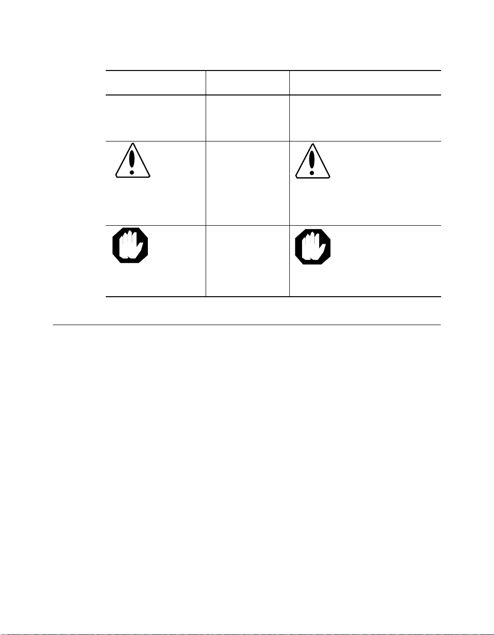
Convention Indicates Example
Note: A Note. The
Caution: A Caution. A
Warning: A Warning. A
Related Docu me nts
This section provides information on supporting documentation, including:
❑ 3Com Documents
information is
important
condition may
damage
software or
hardware
condition may
threaten
personal safety
Note: Use STP lobe
cables for yo ur s yste m.
Caution: Do not put
your installation
diskettes on a
magnetic surface.
This may damage the
diskettes.
Warning: Wear eye
protec tion when
performing these
maintenance
procedures.
❑ Reference Documents
xvi ONline 17-Slot System Concentrator Installation and Operation Guide
Page 17

3Com Documents
The following documents provide additional information on 3Com
products:
17-Slot ONline System Concentrator Installation and Operation
Guide – Explains how to install, operate, and manage the 3Com ONline
17-Slot Syste m Concentrator (Models 5017 C-LS and 5017C with load
sharing) .
6-Slot ONline System Concentrator Installation and Operation
Guide – Explains how to install, operate, and m anage the 3Com ONline
6-Slot System Concentrator.
ONline To ken Ring Management Module User’s Guide – Explains how to
install, operate, and use the 3Com ONline Token Ring Management
Module.
ONline Management Commands Guide – Provides an alphabetized
reference resource describing all ONline management commands.
For a complete list of 3Com documents, contact your 3Com representative.
Reference Documents
The following documents supply related background information:
Case, J., Fedor, M., Scoffstall, M., an d J. Davin, The Simple Network
Management Protocol, RFC 1157, University of Tennessee at Knoxville,
Performance Systems International and the MIT Laboratory for Computer
Science, May 1990.
Rose, M., and K. McCloghrie , Structure and Identification of
Management Information for TCP/IP-based Internets, RFC 1155,
Performance Systems International and Hughes LAN Systems, May 1990.
ONline 17-Slot System Concentrator Installation and Operation Guide xvii
Page 18

Page 19

Introduction
1
This chapter briefly describes the cap abilities and operation of the 3Com
ONline™ System Concentrator. Chapter 2 provides important information
for installing modules and verifying their operation.
If you are uncertain about legal network configurations when using the
ONline System Concentrator, refer to the appropriate ONline media module
manual.
Introducing the ONline Sys tem Conc e ntrat or
The ONline System Concentrator is a modular, fault-tolerant pl atform for
facility networks. The concentra tor has a unique TriChannel® architecture
that allows it to run three network protocols concurrently. It is capable of
running Ethernet, Token Ring, and FDDI networks - all in the same
concentrator.
Ethernet connectivity is available on a variety of major cable types including:
❑ Fiber optic ca ble
❑ Unshielded and Shielded twisted pair wire
❑ Thin and Th ick coaxial cable
Introduction 1 - 1
Page 20
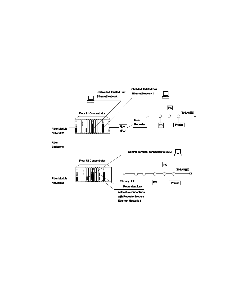
Figure 1-1 shows a mod el syst em that i nclud es ea ch of thes e cable t ypes. I n
this diagram, an ONline Ethernet Repeater Module is connected to a
10BASE5 segment via an AUI cable and a transceiver. Also shown is the
physical connection between an ONline Ethernet Fiber Module and a
10BASE2 segment, via a fibe r cable, fiber media access unit, and IEEE
repeater. Unshielded and shielded twisted pair connections to-the-desk are
also included in this sample configuration.
Figure 1-1. Multiple 17-Slot Concentrator Enviro nment
Network segments attach to the concentrator through media modules you
install into the chassis. The ONline Controller Module, which provides
re-timing and re-transmission of received signals, must be installed in one of
the concentrator's seventeen slots. The remaining sixteen slots can be
configured with any combination of media modules.
1 - 2 ONline 17-Slot System Concentrator Installation and Operation Guide
Page 21
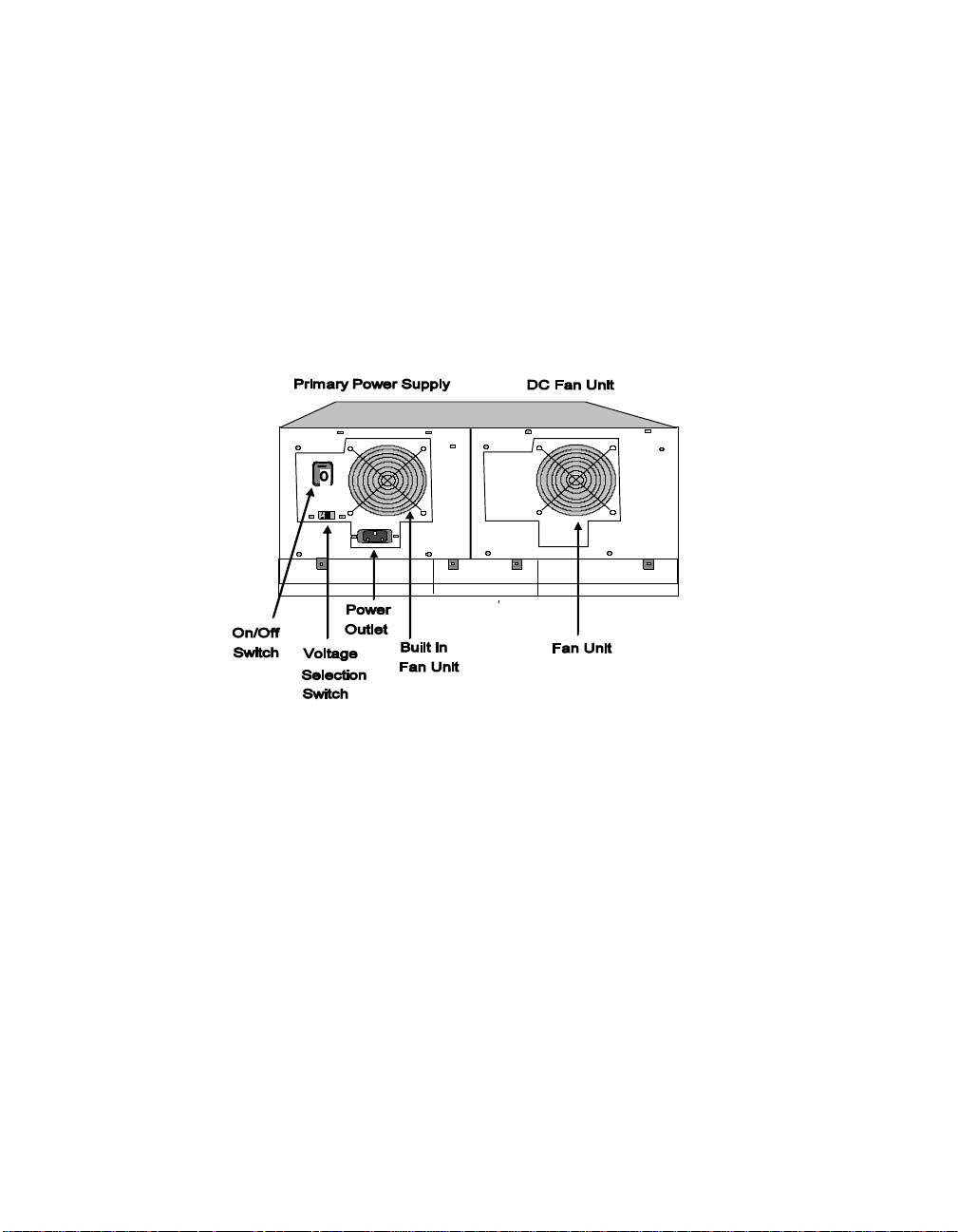
Back Panel
A power supp ly and DC fan unit are installed when you receive your
concentrator. There is an On/O ff switch on the power supply. The power
supply should be powered down when you install or remove it. Note that
there is no need to power down the concentrator for installation or
removal of the media modules. Add itionally, you can repl ace the fan unit
with an optional backup power supply to provide power redundancy.
Figure 1-2. ONline System Concentrator Rear View
Front Panel
The concentrator is shipped with 15 blank faceplates and two empty slots.
The two slots are left empty because you must install the ONline Controller
Module and a t least one media module for the concentrator to be
functional. As you add media modules to your unit, remove blank
faceplates to provide additional slots for the new modules.
Introduction 1 - 3
Page 22
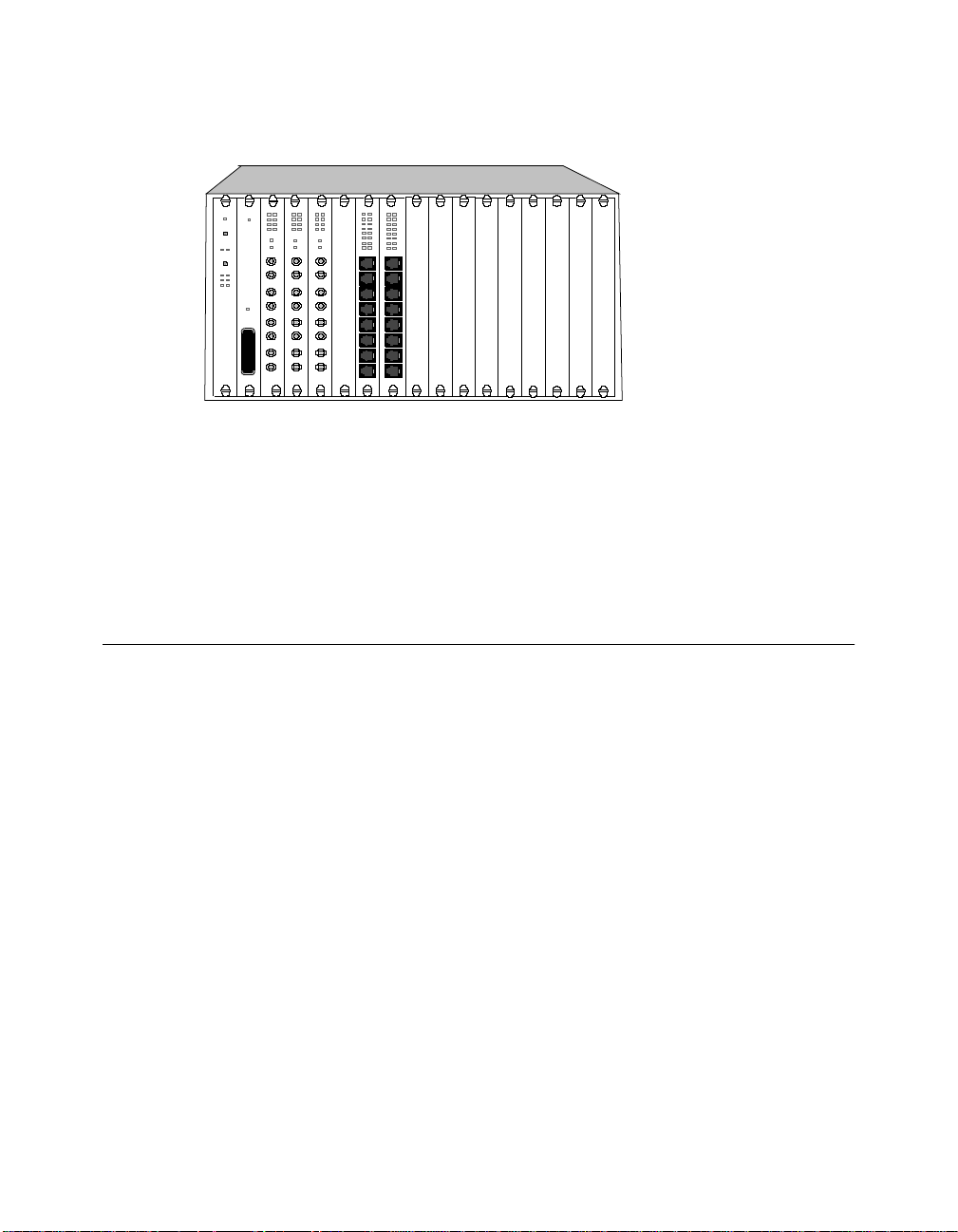
Figure 1-3. ONline System Co ncentrator Front View
A cable tray is provided with the concentrator so that c ables you attach to
the media m odules can be run under the unit and out the back − where
they will not be in the way. A rack mount kit is also provided for the
concentrator and for the cable tray so you can rack mount the enti re unit.
ONline System Concentrator Features
This section describes the major features of the ONline System
Concentrator. The features include:
❑ Modular Desi gn
❑ TriChannel® Architecture
❑ Port-Switching Technology
❑ Fault-Tolerance Capabiliti es
❑ Hot Swapping of Media Modules
❑ Synchronous Backplane
1 - 4 ONline 17-Slot System Concentrator Installation and Operation Guide
Page 23
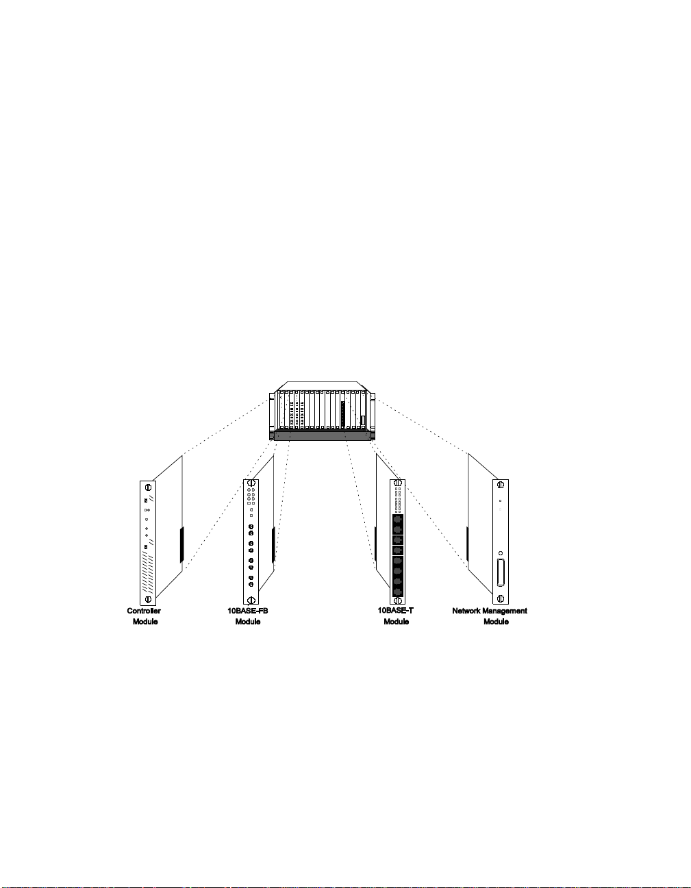
Modular Design
The ONline Concentrator's modular design lets you add different media
modules (such as fiber, twisted pair, and coaxial) in any combination to
connect different types of media segments. A possible configuration is
shown in Figure 1-4. You can link segments of different protocols using
Token Ring, FDDI, bridging and routing modules.
Every concentrator requires one Controller Module that controls
communications between all modules. In addition, a Network
Management Module provides sophisticated monitoring and control of the
modules in the concentrator. As a rack-mounted unit, the ONline
Concentrator can be connected to patch panels to simplify and manage
your network cables.
Figure 1-4. Mod u lar ONline Config u ration
Introduction 1 - 5
Page 24

TriChannel Architecture
The ONline System Concentrator's TriChannel architecture lets you run
Ethernet, Token Ring, and FDDI networks, al l in the same concentrator.
This allows a single ONline unit to do the work of three conventional hubs.
You can also run multiple Ethernet networks or mixture of Ethernet, Token
Ring, and FDDI networks in any combination you want. This architecture is
shown in Figure 1-5.
Any module you add to the concentrator can be assigned to any of three
networks on its backpl ane and can be easily moved to another backplane
network using either an on-board dip switch or remote network
management.
Additionally, any module can be set to “isolated” mode whereby it acts as
an isolated network - not connected to the concentrator backplane. This
mode lets you isolate users from the main network. This can be useful for
security or as a temporary situa tion to preve nt traffic from c ontaminating
the network (for example, if some users are conducting network tests or
running at very high loads.)
Port-Switching Technology
Available port-switching modules allow you to assign any port to any
backplane network using a network management command. This allows
you to perform moves, adds, and changes at the network console, saving
costly and time-consuming trips to the wiring closet. It also allows you to
get additional bandwidth on demand by switching users to lower volume
networks during peak traffic periods.
1 - 6 ONline 17-Slot System Concentrator Installation and Operation Guide
Page 25
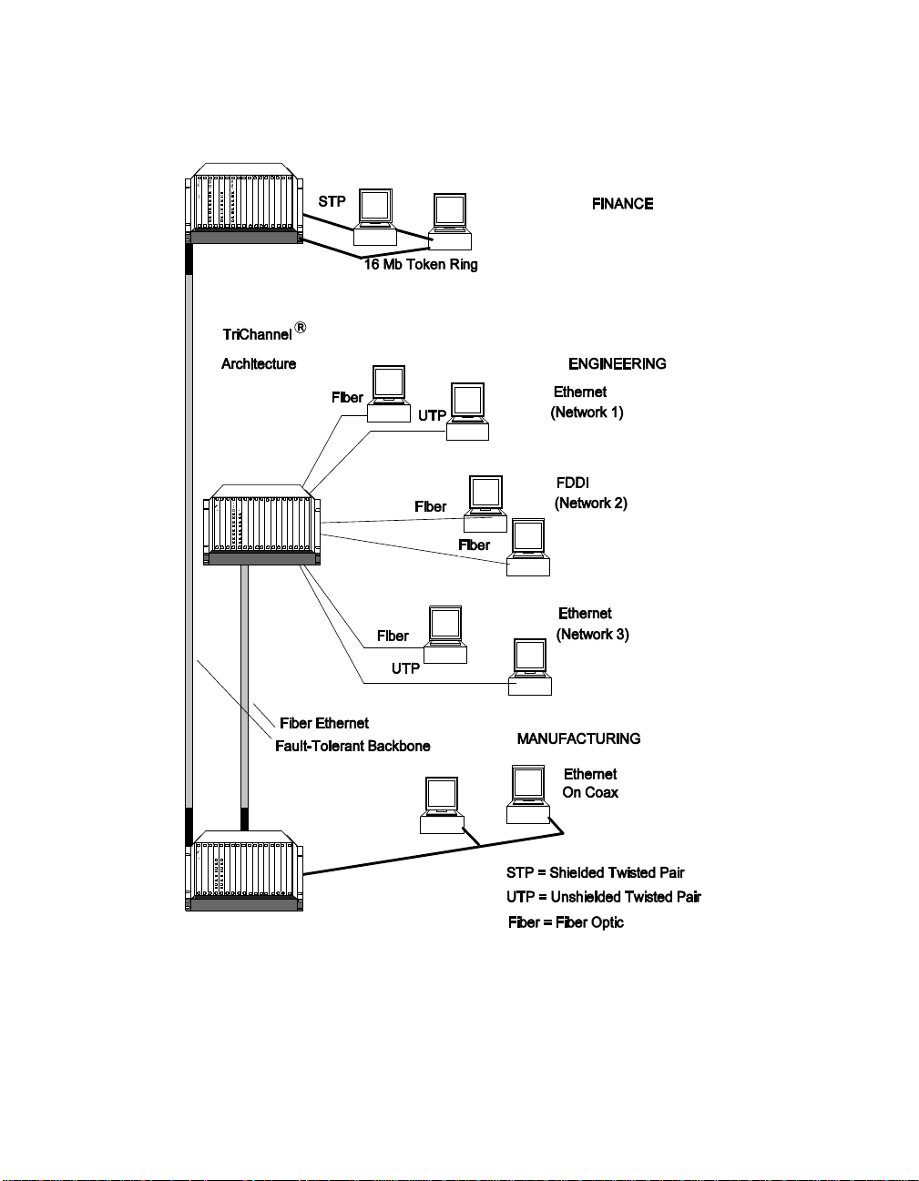
Figure 1-5. ON line System Co ncentrator Using Multiple Networks
Introduction 1 - 7
Page 26

Fault-Tolerance Capabilities
The ONline System Concentrator provides fault tolerance through
redundant features, such as an optional backup power supply, backup
controller module, redundant cable links , and backup concentrator
capability.
Backup Power Supply
An optional second power supply can be used to backup the primary
power supply in case of a power failure. Should the primary power supply
fail, the backup power supply takes over automatically. In addition, once a
backup power supply has been installed, you ca n replace a faile d primary
power supp ly without shutting down the system.
Load Sharing
The load-sharing func tion provi des uninterrupted power to modules
installed in a concentrator with two power supplies. If the active power
supply fails, the concentrator automatically switches to the other power
supply without interrupting the network.
The following ONline 17-Slot System Concentrators have load-sharing
capability:
❑ Model 5017C-LS
❑ Model 5017C with load-sharing upgrade
To determine if your model 5017C concentrator has load-sharing hardware,
check the rear of the concentrator chassis for a label reading “Upgraded
w/30-0 286.” If this label is present, the concentrator has received the
load-sharing upgrade.
In order for load shari ng to work, the Fault-Tolerant Controller Module
model 5000M-RCLS must be installed. This co ntroller monitors the
concentrator's load-sharing function.
1 - 8 ONline 17-Slot System Concentrator Installation and Operation Guide
Page 27

Backup Controller Module
The controller is vital to the system because it performs important functions
including:
❑ synchronizing all modules
❑ monitoring concentrator conditions (temperature, power supply
status, etc.)
❑ recognizing failures
❑ clocking and timing to the ONline Concentrator backplane
By using two 3Com Fault-Tolerant Controller Modules (5000M-RCLS) in
your concentrator you can protect these critica l tasks if a controller fails.
Note: You cannot use the 5000M-RCTL or 5000M-CTL controller
in a load-sharing conc entrator (Model 5017C-LS or Model
5017C with load-sharing upgrade).
Redundant Cable Links
Cable breaks or failures are the most common problem in any network.
Using the ONline Ethernet Fiber Module in your ONline System
Concentrator enables you to implement full cable redundancy for your
network's backbone. Thereafter, if one port should fail, or if a cable is
disconnected or cut, the b ackup port will take over in 100 milliseconds. A
sample redundant network connection is shown in Figure 1-6.
Introduction 1 - 9
Page 28

Figure 1-6. Redundant Cable Link Configuration
Backup Concentrator
A second concentrator or 3Com Fiber Ethernet Star Coupler may be used
to backup the primary concentrator in a star-wired network. This provides
full fault t olerance for a backbone c able plant.
1 - 10 ONline 17-Slot System Concentrator Installation and Operation Guide
Page 29

Figure 1-7. Backup Concentrator Configuration
Hot Swapping of Media Modules
Media modules can be added, removed, and reconfigured without
powering down the ONlin e System Conc entrator or affecting the rest of
the network. This means that you can add entire new segments or make
minor system adjustments during normal working hours withou t
interrupting the entire system.
Introduction 1 - 11
Page 30

Synchronous Backplane
The ONline System Concentrator backplane is designed with all passive
components to achieve the maximum reliability. The synchron ous
backplane allows the concentrator to be connected (using the 3Com
ONline Fiber Module) without the need for internal repeaters. This avoids
the limitations of the Ethernet four-repeater rule and lets you connect up to
23 concentrators serially, without the need for an intervening repeater or
bridge.
1 - 12 ONline 17-Slot System Concentrator Installation and Operation Guide
Page 31

2
This chapter describes how to install the ONline System Concentrator, how
to install ONline modules, and how to install the optional backup power
supply into y our ONline uni t.
Warning: Do not turn the concentrator's power supply switch on until
Installation and
Troubleshooting
you are instructed to do so in the following procedures.
The information and procedure s contained in this chapter
are to be used only by service personnel to install and
maintain the ONline 17-Slot System Concentrator.
Contents of the Shipping Box
The ONline System Concentrator is a chassis that enables installation of
media modules for network connection. The unit is shipped complete with
the following parts:
❑ Chassis containing:
– singl e power supply
– fan unit
Installation and Troubleshooting 2 - 1
Page 32

– 15 blank faceplates
❑ Chassis rack mount kit
❑ Cable tray with rack mount kit
❑ ONline Fault-Tolerant Controller Module and ONline Fault-Tolerant
Controller Module Ins tallation Guide
❑ Power cord
❑ This ONline System Concentrator Installation and Operation Guide
The pow er cord and hardware items are shown in Figure 2-1.
ONline System
Power Cord
Cable Tray
Rack
Mount Kit
Concentrator
Rack Mount
Controller
Figure 2-1. ONline System Concentrator Shipping Box Contents
2 - 2 ONline 17-Slot System Concentrator Installation and Operation Guide
Page 33

If an y o f t h es e it ems are d amaged or mi ssing, c on ta ct your l oc al s up plier or
a 3Com se rvice representative.
3Com suggests you keep the carton and anti-static shielding ba g in which
your unit was shipped in case you later want to repackage the unit for
storage or shipment.
We also suggest that you record the serial number of your Controller
Module. We have provided a log for this and other information specific to
modules under the Slot Usage Char t in Appendix B nea r the end of this
manual.
FCC Regulations
FCC regulations require that blank faceplates cover slots that are not being
used. To comply with this regulation, the concentrator is shippe d with 15
blank faceplates and two empty slots. These two slots are left empty
becau se t he ONl in e Con tro ller Modu le an d at l ea st one media modu le mu st
be installed for the concentrator to be functional.
Caution: Do not turn the concentrator's power supply switch on
until you have:
❑ verified tha t the selected site meets the installation requirements
outlined in the following pages
❑ completed each of the steps outlined in Table 2-1.
– Be sure to verify that the correct voltage level has been
selected. An improper setting may damage the power
supply.
Installation and Troubleshooting 2 - 3
Page 34

Site Selecti on Considerations
The concentrator can be placed almost anywhere within your company,
including offices and computer rooms. In general, we recommend
installation in a wiring closet. The unit has been designed for rac k
mounting and come s with all the necessary hardware.
Location Requirements
The area where you install the ONline System Concentrator must meet the
following conditions:
❑ Temperature b etween 0° to 50° C (32° to 122° F)
❑ Relative humidity less than 95%, non-condensing
❑ AC power source withi n 6 feet (2 meters). Note that for installation
to have true backup power, two independent AC power sources are
required
❑ The tabl e or rac k wh er e the un it i s in st a ll ed sho ul d b e le ve l and n ot i n
direct sunlight or in an excessively dusty location
Ventilation
The concentrator fan units draw air in through the front and bottom of the
chassis and exhausts air out the back. Make sure there are at least 6 inches
(15 centimeters) between the fan vents at the back of the unit and the
nearest surface to allow adequate airflow for cooling. This minimum
distance is also required for access to the rear of the unit for maintenance.
The cable tray that comes standard with the concentrator helps prevent a
tangle of cables at the front of the concentrator and also permits the
required airflow to the unit. Make sure the cable tray is installed below the
unit correctly before installing the concentrator.
2 - 4 ONline 17-Slot System Concentrator Installation and Operation Guide
Page 35

Caution: The concentrator should have two fans running at all
times to cool the unit properly. You should therefore
have: (A) a power supply (with b uil t-in fan) and a fan
unit installed or (B) two power supplies installed.
Power Requirements
3Com recommends using a 15 ampere electrical wire (branch circuit) to
supply power to the concentrator. This circuit must be grounded to a
safety ground (protected earth ground), not to neutral that carries current
back to the transformer. Do not use the electrical conduit pipe as the only
means of grounding.
Rack Mount Installation Requirements
For rack mount installation of the ONline System Concentrator you need a
standard nineteen-inch EIA config ured rack. The rack and its environment
also should meet the following specifications:
❑ If the rack has an open back and sides:
– the rack must be bolted to the floor
– the top of the rack may need to be braced to the wall
❑ the rack must be grounded
❑ there must be 10.5" (26.7 cm) (6U) of vertical space in the rack for
each 17-slot concentrator
❑ the unit location in the rack must be less than 6 feet (2 meters) from
the nearest AC outlet
❑ patch panels should already be installed in the rack for easier cable
management
Installation and Troubleshooting 2 - 5
Page 36

Table Top Installation Requirements
For table top or shelf mount installation of the ONline System Concentrator
you must make sure the table or shelf can suppo rt 100 pounds (45 kg) for
a fully loaded 17-slot conc entrator. (The concentrator itself, fully loaded
and with cable tray, weighs almost 75 pounds/34 kilograms.) The
table/shelf als o must be less than 6 feet (2 me ters) from the ne arest AC
outlet.
To ensure proper airflow to the un it, you should leave at least 1.75"
(4.45cm) of space below the concentrator (provided by the installed rubber
feet) and by installing the cable tray below the concentrator.
Installation
Table 2-1 prov id es a qui ck d es cr ipt i on of th e s tep s yo u m ust f ol lo w to i ns tall
the ONline System Concentrator as well as reference to the section in this
manual where the step is described. It is important that you perform the
steps in the order ind icated, noting that Step 3 is optional.
Table 2-1 . Steps for Installing the ONline System Concentrator
Step Action Section
1 Install the cable tray into a
rack or place it on a table
top.
2 Install the concentrator unit
into a rack or place it on a
table top.
3 Install the backup power
supply in the concentrator.
2 - 6 ONline 17-Slot System Concentrator Installation and Operation Guide
“Installing the Cable Tray”
“Installing the ONline System
Concentrator”
“Installing the Backup Power
Supply (Optional)”
Page 37

Table 2-1 . Steps for Installing the ONline System Concentrator
(Continued)
4 Set up the power supply. “Selecting the Power Supply
Voltage”
5 Install the ONline Controller
Module in the concentrator.
6 Inst all media modules in the
concentrator.
7 Connect the network
cables to the media
modules.
8 Power up all network
devices and verify the
installation.
Installing the Cable Tray
The cable tray that comes standard with the concentrator helps to manage
the cables that run from the front of the unit so they are fed under the unit
and out through the back. The tray also provides the required space
between the bottom of the unit and the next device in the rack (or the top
of the table) so there is adequate air flow to cool the unit.
“Installing ONline Modules”
“Installing ONline Modules”
“Connecting Network Cables”
“Power Up and Verification”
Caution: If you choose not to use the c able tray beneath your
unit, you must ensure that 1 3/4" (4.45 cm) of space is
open below the ONline unit to ensure adequate
incoming airflow (provided by the installed feet).
Installation and Troubleshooting 2 - 7
Page 38

Cable Tray Rack Mounting
To install the concentrator in a rack , first install the cable tray and then
install the concentrator above the tray. The cable tray can be mounted in
four separate configurations in your rack depending on your preference.
The options are described in Table 2-2 and shown in Figure 2-2.
Table 2-2. Rack Mount Settings
Option Rack Setting Function
1 Flush Mount Flush mounts the unit to the front of
the rack.
2 1/2" Recess Recesses the unit 1/2" (1 .3 cm) from
the front of the rack.
3 2 1/8" Recess Recesses the unit 2 1/8" (5.4 cm) in
a rack.
4 2 3/4" Rec ess Recesses the unit 2 3/4" (7.0 cm) in a
rack.
Note: The ONline System Concentrator is 18.3" (46.5 cm) deep.
Some shallow rack cabinets may only allow you to flush
mount the unit. In addition, make sure you mount the unit
so that cables connected to the media modules hav e
enough room to bend (especially important for fiber
cables).
2 - 8 ONline 17-Slot System Concentrator Installation and Operation Guide
Page 39

Figure 2-2. Rack Mount Po sitions
Follow the steps below to mount the cable tray in yo ur rack:
1. Attach the two rack mount flanges to the cable tray in the position
you want as shown in Fi gure 2-2 using th e eight (8) provided 8-32 x
1/4" flathead screws - four per side.
Note: You must tighte n the screws completely to be fl ush
with the rack mount flanges so the tray will fit in the
rack.
2. Select a vacant position in the rack that is at least 10.5 inches (26.7
cm) from the top of the rack or the next higher unit in the rack.
3. Install the provided clip nuts onto the front of the rack where you
want to attach the tray.
Installation and Troubleshooting 2 - 9
Page 40

Note: The function of the clip is to hold the nut in place behind
the rail. Be sure to install the clip onto the rail so that the
nut is centered behind the hole through which you plan to
insert the screw.
4. Place the tray in the rack and attach to the clip nuts through the front
of the rack using the four (4) 10-32 x 5/8" truss-head screw s and as
shown in Figure 2-3.
Figure 2-3. Cable Tray Installation in Rack
Cable Tray Table Mounting
To install the concentrator on a table top or on a shelf, place the cable tray
on the surface first and then place the concentrator on top of the tray.
Note that the four rubber feet must be installed on the concentrator before
it is placed on the table top or on top of the cable tray. The feet fit into the
four holes in the cable tray, which prevents the concentrator from moving.
2 - 10 ONline 17-Slot System Concentrator Installation and Operation Guide
Page 41

Installing the ONline System Concentrator
The ONline System Concentrator can be placed on top of a table or a shelf,
or mounted in a rack. Make sure the cable tray has been install ed first on
the table or in the rack (or that 1 3/4" (4.5 cm) of vertical space has been
provided below the unit for air flow) an d that the loc ation meets all the
environmental considerations specified earlier in this chapter.
Caution: 3Com recommends that two people install the unit
since it weighs 38 lbs (17 kg) with one power supply
and 46 lbs (24 kg) with the backup po wer supply
installed.
3Com also recommends installing the backup power supply
prior to rack mounting the unit (see the section titled
Installing the Backup Power Supply later in this chapter). In
some rack cabinets, the rear of the c abinet may interfere
with installation or removal of the power supply and fan.
Rack Mounting the ONline System Concentrator
The ONline System Concentrator can be mounted in four different
configurations in the rack. Use the same rack settings for both the cable
tray and the concentrator. If you are not installing the cable tra y in the
rack, you should select the concentrator mount setting at this time. Refer
to Table 2-2 and Figure 2-2 in the “Cable Tray Rack Mounting” section for
specifics about the four mounting settings.
Follow the steps below to mount the concentrator in your rack:
1. Attach the two rack mount flanges to the ONline concentrator unit in
the position you want as shown in Figure 2-4 using the eight (8)
provided 8-32 x 1/4" flathead screws - four per side.
Installation and Troubleshooting 2 - 11
Page 42

Caution: You must use the supplied 8-32 x 1/4" screws to attach
the rack mount flanges. A longer screw may extend
too far into the ONline chassis and disrupt the
installation of modules.
Figure 2-4 . A ttaching the Rack Mount Flanges
2. Install the provided clip nuts onto the front of the rack where you
want to attach the unit. See Figure 2-3 for proper orientation.
3. Slide the unit in the rack above the installed cable tray until the rack
mount flanges seat flush to the front of the rack.
Caution: While mounting the concentrator, do not leave the unit
resting on the mounted ca ble tray since the c able tray
rack mounts may not support a fully-loaded
concentrator.
4. Secure th e unit to the rack with the four (4) 10-32 x 5/8" truss-head
screws as shown in Figure 2-5.
2 - 12 ONline 17-Slot System Concentrator Installation and Operation Guide
Page 43

Figure 2-5. Chassi s Mounted i n Rack
Table Top Mounting the ONline Concentrator
You can set the ONline Concentrator directly on a table top or shelf that
can support at least 100 pounds (45 kg). A fully load ed concentrator
weigh s ab out 75 l bs ( 3 4 k g) . 3C om reco mme nd s yo u s et t he u nit on top of
the ONline cable tray as the cable tray provides a central area for cable
management and provides the required 1 3/4" (4.5 cm) of clearance for
sufficient air flow. Regardless of whether the cable tray is used or not, the
four (4) rubber feet must remain on the bottom of the unit.
If the cable tray is used, place the ONline unit on top of the cable tray and
insert the rubber feet from the unit into the holes in the cable tray, which
stabilizes the unit on the tray.
If the cable tray is not used, place the unit on the table or shelf.
Installation and Troubleshooting 2 - 13
Page 44

Installing the Backup Power Supply (Optional)
Install the backup power supp ly in the ONline System Concentrator (if
ordered). This power sup ply provides p ower redundancy if the primary
power supp ly should fail. Skip this section if you do not have a backup
power supply.
To install the backup power supply, you must first remove the fan unit from
the power supply slot in the back of the unit. Follow the steps below to
install the backup power supply:
1. Remove and save the four screws that attach the fan unit to the rear
of the concentrator as shown in Figure 2-6.
Figure 2-6. Removing Fan Unit
2. Carefully remove the fan unit and disconnec t the fan unit wiring
harness from the connector inside the base of the ONline u nit as
shown in Figure 2-7. Save this fa n unit in case a power s u pp ly s h ou ld
fail at a later ti me and you need to reinstall the fan unit.
2 - 14 ONline 17-Slot System Concentrator Installation and Operation Guide
Page 45

Figure 2-7. Unplugging the Fan Unit
Before you install the new power supply, chec k the label on the inside of
the power supply bay that explains where each of the seven power leads
from the power supply are connected in the concentrator chassis.
Power leads labeled P7, P8, and P9 fit in the back three raised connectors
and they are “keyed” so they can be inserted only in the correct
connector and only in one direction. Power leads labeled P10, P11, P12,
and P13 fit in the front four recessed connectors and can be ins erted in
only one direction. These connectors are shown in Figure 2-8.
Installation and Troubleshooting 2 - 15
Page 46

Figure 2-8. Power Supply Conne ct ors
3. Hold the backup power supply in one hand while using your other
hand to plug in the seven (7) le ads from the power supply as shown
in Figure 2 -9.
Figure 2-9. Installing the Backup Power Supply
2 - 16 ONline 17-Slot System Concentrator Installation and Operation Guide
Page 47

4. Make sure the cable is pushed up to the right side and then slide the
power supply into the b ack of the concentrator as shown in
Figure 2-10. Then fasten with the four (4) s crews you removed
earlier from th e fan unit.
Figure 2-10. Installed Backup Power Supply
Selecting the Power Supply Voltage
Before you plug in the power cord to the power connector on the power
supply (and to the backup pow er supply, if you have one), you must verify
that the voltage selector is correctly set for your country line voltage.
Caution: An incorrect voltage setting can damage the power
supply.
1. Set the power switch to the Off (O) position.
Installation and Troubleshooting 2 - 17
Page 48

2. Use a flat-blade screwdriver to move the voltage selector switch so
the setting that is appropriate for your country's line voltage is
showing: 100/120 Volts or 220/240 Volts, as shown in Figure 2-11.
Figure 2-11 . Setting the Voltage Selector Switch
3. Plug in the power cord to the power conn ector on the ba ck of the
concentrator and connect the other end to an outlet. If you installed
a backup power supply, make sure that power cord is connected to
an outlet on an independent circ uit from that used for the primary
power supp ly.
The power receptacle on the concentrator is an approved IEC
connec tor. Make sur e the power cord you u se is appr opr iat e for you r
country line voltage:
❑ For 100/120 Volt operation, use only a power cord rated for 10
Amps, 125 Volts.
❑ For 220/240 Volt op eration, use only use a power cord rated for
10 Amps, 250 Volts.
2 - 18 ONline 17-Slot System Concentrator Installation and Operation Guide
Page 49

Warning: DO NOT use a 3-to-2 pronged adapter at the outlet since
this may result in elec trical shock and does not provide
adequate grounding.
Installing ONline Modules
Warning: Only service personnel should install ONline modules.
Install the ONline Controller Module in the concentrator as described in the
ONline Controller Module Installation Guide provide d with the Controller
Module.
Install any ONline media modules in the ONline System C oncentrator as
described in the manual provided with each module. Note that you do not
need to turn off the concentrator when installing additional modules to
your co nce n trator.
Use the chart in Append ix B to label the location of each module in the
concentrator. At least one m edia module must be installed along with the
Controller Module to m ake the conc entrator functional.
Connecting Network Cables
Connect the network cables betw een conce ntrators, patch panels , and
transceivers.
Installation and Troubleshooting 2 - 19
Page 50

Figure 2-12. Network Cable Connections
Power Up and Verification
This section tells how to power up the concentrator and verify that it is
working correctly.
Switch the power supply O n/Off switch to the On (|) pos ition .
The Power Supply LED(s) on the ONline Controller Module light when the
unit is powered up correctly. The verification procedure i s split into the
following areas:
❑ fan operation
❑ power supply operation
❑ netwo rk operation
2 - 20 ONline 17-Slot System Concentrator Installation and Operation Guide
Page 51

Fan Operation Verification
To verify that the fan unit and the power sup ply fan are functio ning
correctly you need to visually inspect the fan unit(s) on the rear of the
concentrator to make sure they are turning and that nothing is blocking
their path.
Power Supply Operation Verification
Verify that the LEDs on the Controller Module appear as defined in
Table 2-3 to check the operation of the power supply.
Table 2-3. Controller Module LEDs After Proper Power-Up
LED Proper State
Primary Power On.
Backup Power On. A backup power supply is installed.
Off. No backup power supply is installed.
Temperature (TEMP) Off.
Installation and Troubleshooting 2 - 21
Page 52

If any of these LEDs are not lit as shown in this chart, refer to Table 2-4 to
troubleshoot the problem.
Table 2-4. Troubleshooting with Controlle r Module LEDs
LED State
Primary
Power
Off The Primary
Steady
Blinking
Possible
Problem
Power LED is
broken.
The primary
power supply
is not properly
installed.
The primary
power supply
has failed.
Troubleshooting
Suggestions
Press the LED Test button
to verify that the LED is
working properly.
Reinsta ll the primary
power supply and turn it
on.
Verify that the outle t is
supplying power.
Verify that the voltage
selection switch is set to
the correct position for
your country's line
voltage.
Verify that the power
cord is plugged in at
both ends and that the
cord is appropriate for
your country's line
voltage.
Verify that the power
switch is turned on.
Replace the power
supply.
2 - 22 ONline 17-Slot System Concentrator Installation and Operation Guide
Page 53

Table 2-4. Troubleshooting with Controlle r Module LEDs
(Continued)
LED State
Primary
Power
(cont.)
Steady
blinking
(cont.)
Two blinks,
then a pause
(in unison
with Backup
Power LED)
Possible
Problem
The primary
power supply
is not properly
installed.
The pow er
load-sharing
hardware is in
an error state.
Troubleshooting
Suggestions
Reinsta ll the primary
power supply and turn it
on.
If a management mod ule
is installed, the
concentrator should
recover automatically
from this condition. If it
doesn't, reset the
concentrator using the
RESET CONCEN TRATOR
command. If this fails to
correct the condition,
turn both power
supplies OFF, then ON
again.
If a management mod ule
is not installed, turn both
power su ppli es OFF, then
ON agai n.
Backup
Power
Off The Backup
Power LED is
broken.
The backup
power supply
is not properly
installed.
Installation and Troubleshooting 2 - 23
Press the LED Test button
to verify that the LED is
working properly.
Reinsta ll the backup
power supply and turn it
on.
Page 54

Table 2-4. Troubleshooting with Controlle r Module LEDs
(Continued)
LED State
Backup
Power
(cont.)
Temp Blinking The
Steady
blinking
(cont.)
Two blinks,
then a pause
(in unison
with Primary
Power LED)
The backup
power supply
has failed.
The backup
power supply
is not properly
installed.
The pow er
load-sharing
hardware is in
an error state.
temperature in
the
concentrator is
too high.
Possible
Problem
Troubleshooting
Suggestions
See Prima ry Power LED
suggestions for same
State and Possible
Problem (above).
Reinsta ll the backup
power supply and turn it
on.
See Primary Power LED
suggestions for same
State and Possible
Problem (above).
Verify tha t the fan units
are working and nothing
is blocking airflow from
the front and bottom of
the concentrator.
Active Off The module is
in standby
mode.
2 - 24 ONline 17-Slot System Concentrator Installation and Operation Guide
Verify at least 1 3/4"of
space below the
concentrator for proper
air flow.
Lower the temperature in
the room.
Verify tha t the Standby
LED is illuminated.
Page 55

Table 2-4. Troubleshooting with Controlle r Module LEDs
(Continued)
LED State
Standby Off The mod ule is
Blin king There is a
Possible
Problem
The Active LE D
is broken.
in active mode.
The Stand by
LED is broken.
hardware
failure in the
Standby
module.
Troubleshooting
Suggestions
Press the LED Test button
to see if the LED is
working.
Verify that the Active LED
is illuminated.
Press the LED Test button
to see if the LED is
working.
Reset the module. If this
action does not correct
the probl em, install the
module in another slot.
If necessary, replace the
module and contact
3Com Customer
Support Organiza tion.
See Technical A s sis ta nc e
to follow.
Technical As sist anc e
You can receive assistance for installing and troubleshooting the 17-Slot
concentrator by calling your dealer or 3Com Customer Support. Be
prepared to supply a representative with th e following information:
❑ a description of the problem
❑ the steps you have taken to try and correct the problem
Installation and Troubleshooting 2 - 25
Page 56

❑ the configuration of your concentrator
❑ the screen information reporting the SHOW DEVICE command (if you
have an ONline management module installed in the concentrator)
Refer to Ap pendix C for in structions how to contac t Technical
Support for your product.
Where To Go From Here
Once you have made the necessary concentrator connections, and have
verified that communication has been established between all segments
connected to the concentrator, no further installation procedures are
required. Chap ter 3, Maintenance, discusses what to do in the event that
the fan unit or power supply needs to be repla ced.
2 - 26 ONline 17-Slot System Concentrator Installation and Operation Guide
Page 57

3
This chapter describes routine maintenance designed to keep your ONline
System Conce ntrator working at its best . It also explains how to replace a
failed power supply o r fan unit.
This chapte r explains the fo ll owing maintenance procedures:
Maintenance
❑ Routine Maintenance
❑ Power Supply Replacement
❑ Fan Unit Replacement
❑ ONline Module Maintenance
❑ Other System Components
Warning: There are no serviceable parts on either the power supply
or the fan unit. If either of these parts fail, remove them as
described in this chapter and return them to your reseller or
to 3Com Corporation. You sho uld keep replacemen t
power supply and fan units at your site so they are available
if needed.
Maintenance 3 - 1
Page 58

Routine Maintenance
You should inspect your equipment to make sure that all of the following
are true:
❑ all the blank faceplates are on
❑ the fans are running
❑ there are no obstructions to the ventilation on the concentrator
❑ the ONline Controller Module and media module LEDs are registering
correctly
Replacing the Powe r Supp ly
Both the primary and backup power supplies in the ONline System
Concentrator are removed and installed in exactly the same manner. If a
power supply should fail and switch over automatically to the backup
power supply (optional) you can replace the failed power supply while the
unit is operating - without disrupting network operation.
Caution: Improper installation of the power supply could
damage the power supply.
Follow the steps below to replace a power supply unit:
1. Switch Off the failed power supply, then unplug the power cord from
both the wall and from the back of the power supply.
2. Remove and save the four screws that attach the power supply to the
rear of the concentrator as shown in Figure 3-1.
3 - 2 ONline 17-Slot System Concentrator Installation and Operation Guide
Page 59

Figure 3-1. Removing the Power Supply
3. Carefully pull the power supply out from the concentrator and
disconnect the seven (7) power leads from the conne cto rs inside the
base of the ONline unit as shown in Figure 3-2.
Maintenance 3 - 3
Page 60

Figure 3-2. Unplugging the Power Supply
Note: Before you install the new power supply, check the label on
the inside of the power supply bay that explains where
each of the seven power leads from the power supply are
connected in the concentrator chassis.
Power leads labeled P7, P8, and P9 fit in the back three
raised connectors and they are “keyed” so they can be
inserted only in the correct connector and only in one
direction. Power leads labeled P10, P11, P12, and P13 fit in
the front four recessed connectors and can be inserted in
only one direction.
4. Pick up the new power sup ply and plug in the seven (7) power leads
from the power supply as shown in Figure 3-3.
3 - 4 ONline 17-Slot System Concentrator Installation and Operation Guide
Page 61

Figure 3-3. Power Supply Plugs in ONline System Concentrator
5. Make sure the cable is pushed up to the right side and slide the
power supply into the back of the concentrator and fasten it with the
four (4) screws you removed from the defective unit as shown in
Figure 3-4.
Maintenance 3 - 5
Page 62

Figure 3-4. Backup Power Supply Installed
6. Set the voltage selection switch on the back of the new power supply
to the same setting as the old power supply (or as explained in the
“Selecting the Power Supply Voltage” section in Chapter 2) and turn
the power swit ch to the Off (0) position.
7. Plug in the power cord to the powe r supply and to the wall outlet,
then turn the power switch to the On (|) position.
8. Check the power supply LEDs on the controller module to verify that
the new power supply is working correctly. Make sure the fan on the
power supply is running.
3 - 6 ONline 17-Slot System Concentrator Installation and Operation Guide
Page 63

Replacing the Fan Unit
A fan installed in either the left or right bays is removed or installed in
exactly the same manner as the power supply. Follow the steps below to
replace a fan unit:
Caution: The concentrator must have two fans running at all
times to cool the unit. This is achieved through the
power supply fan and the fan uni t that come standard
with the concentrator, or by having two power supplies
installed.
1. Remo ve and save the four screws that attach the fan to the rear of
the concentrator as sh own in Figure 3-5.
Figure 3-5. Remov ing the Fan Unit
Maintenance 3 - 7
Page 64

2. Carefully pull the fan unit out from the concentrator and disconnect
the wiring harness from the plug inside the base of the ONline unit as
shown in Figure 3-6.
Figure 3-6. Unplugging the Fan Unit
3. Pick up the new fan unit and plug the fan power lead in the same
connector in the base of the ONline unit from which you removed
the old fan (plug P0).
4. Slide the new fan unit into the back of the concentrator and fasten it
to the unit with the four (4) screw s you removed fro m the defective
unit as shown in Figure3-7.
3 - 8 ONline 17-Slot System Concentrator Installation and Operation Guide
Page 65

Figure 3-7. Fan Unit Installed
ONline Module Maintenance
Refer to the ONline installation guides that come with the modules for
installation and operation i nformation.
Other System Components
For maintenance other than hot swap of power supply, fan, and modules
described previously in this section, the following applies:
Caution: This unit may have one or two power supply cords.
Disconnect all power supply cords before servicing to
avoid electrical shock.
Maintenance 3 - 9
Page 66

Vorsicht: Dieses gerät hat eine oder zwei netzverbindungen. Vor
wartung des gerätes alle netzstecker ziehen um
elektroschock zu vermeiden.
3 - 10 ONline 17-Slot System Concentrator Installation and Operation Guide
Page 67

A
General
Network Protocols Sup ported:
Ethernet/IEEE 802.3 over various media
IEEE 802.5 Token Ring over various media
ANSI FDDI
Environmental
Operating te mp erature: 0° to 50° C (32° to 122° F)
Specifications
Storage temperature: -30° to 65° C (-22° to 149° F)
Operating humidity: less than 95%, non-condensing
Specifications A - 1
Page 68

Mechanical
Dimensions: 17.5"W x 18.3"D x 8.75"H (44.5 cm x 46.5 cm x 22.2 cm)
Weight: unloaded, with one power supply: 38 lb. (17 kg.)
Power So urce
90-132 VAC, 6 Amps
180-264 VAC, 3 Amps, 47-63 Hz
325 Watts
1700 BTU/hr
unloaded, with two power supplies: 46 lb. (21 kg.)
loaded, with two power supplies: 75 lb. (34 kg.)
Regulatory Compliance
Safety: UL, CSA, and TUV certified.
Emissions: FCC/A, VDE/B, and VCCI/1 certified.
A - 2 ONline 17-Slot System Concentrator Installation and Operation Guide
Page 69

Accessories
Cable Management Tray (5000CT): 17.5"W x 18.3"D x 1.75"H
Rack-Mount Kit (5017RM): 2.5 lb. (1.2 kg.)
Backup Power Supply (5017PS-325): 8 lb. (3.6 kg.)
Front Cover Panel (5017FC): .5 lb. (.23 kg.)
(44.5 cm x 46.5 cm x 4.5 cm)
8 lb. (3.6 kg.)
Specifications A - 3
Page 70

Page 71

B
Slot Usage Chart
The ONline System Concentrator has seventeen slots, sixteen of which are
available slots for installing media modules (one slot is occupied by the
ONline Controller Module). The slot on the far le ft is slot numb er 1 and
runs to slot 17 on the far right. Use the chart on the next two pages to
keep track of the following:
❑ which module is installed in each slot
❑ which network (channel) each module is set for (or if it is isolated)
❑ any general remarks, such as module serial number or module
specific configuration settings
Store any oth er information on this chart tha t you think wi ll be helpful
when ad ding new modu les or when di ag nosing network que stions.
Table B-1. Concentrator Slot Usage Chart
Slot
1
2
Module
Type
Network
or Isolated)
(#
Remarks
Slot Usage Chart B - 1
Page 72

Table B-1. Concentrator Slot Usage Chart (Continued)
Slot
3
4
5
6
7
8
Module
Type
Network
or Isolated)
(#
Remarks
9
10
11
12
B - 2 ONline 17-Slot System Concentrator Installation and Operation Guide
Page 73

Table B-1. Concentrator Slot Usage Chart (Continued)
Slot
Module
Type
Network
or Isolated)
(#
Remarks
13
14
15
16
17
Slot Usage Chart B - 3
Page 74

Page 75

Technical Support
C
3Com provides easy access to technical support information through a
variety of services. This appendix describes the following services:
❑ On-line Technical Services
❑ Support from Your Network Supplier
❑ Support from 3Com
❑ Returning Products for Repair
On-line Technical Support
3Com offers worldwide product support through the followin g on-line
systems:
❑ Email Technical Se rvice
❑ World Wide Web Site
Technical Suppo rt C - 1
Page 76

Email Technical Support
You can contact the Integrated Systems Division (formerly Chipcom) on the
Internet for technical support using the e-mail address
techsupp@chipcom.com.
World Wide Web Site
You can ac cess the latest networking information on the 3Com World
Wide Web site by entering our URL into your Internet browser:
http://www.3Com.com/
This service features news and information about 3Com products,
customer serv ic e and support, the 3Com latest news releases , selected
articles from 3TECH™, the 3Com award-winning technical journal, and
more.
You can contact the Integrated System s Division o n the World Wide Web
by entering our URL into your Internet browser:
http://www.chipcom.com/
There are li nks between both WWW page s to view informatio n from all
3Com divisions.
Support from Your Network Supplier
If additional assistance is required, contact your network supplier. Many
suppliers are authorized 3Com service partners who are qualified to provide
a variety of services, including network planning, installation, hardware
maintenance, application training, and support services.
C - 2 ONline 17_Slot System Concentrator Installation and Operation Guide
Page 77

When you contact your network supplier for assistance, have the following
information ready:
❑ Diagnostic error messages
❑ A list of system hardware and software, including revision levels
❑ Details about recent configuration changes, if applicable
If you are unable to contact your network supplier, see the following
section on how to co ntact 3Com.
Support from 3Com
If you are unable to receiv e support from your network supplier, technical
support contracts are a va il able from 3Co m.
For direct access to customer service for Integrated Systems Division
products (formerly Chipco m) in:
❑ U.S.A. and Canada - call (800) 724-2447
❑ Asia Pacific - call (508) 787-5151
❑ Europe - Refer to table below
Country Telephone Number Co untry Telephone Number
Belgium 0800 71429 Netherlands 06 0227788
Denmark 800 17309 Norway 800 11376
Finland 0800 113153 Spain 900 983125
France 05 917959 Sweden 020 795482
Germany 0130 82 1502 U.K. 0800 966197
Ireland 1 800 553117 U.S. 800 876-3266
Italy 1678 79489
Technical Suppo rt C - 3
Page 78

For access to customer service for all 3 Com products, call (800) 876-3266.
You can also contact the Integrated Systems Division (ISD) on the Internet
by using the e-mail address techsupp@chipcom.com.
Returning Produc ts for R epair
A product sent directly to 3Com for repair must first be assigned a Return
Materials Authorization (RMA) number. A product sent to 3Com without
an RMA number will be returned to the sender unopened, at the sender’s
expense.
To obtain an RMA number for Integrated Systems Division products
(formerly Chipcom ), use the following numbers .
Country Telephon e Number Fax Number
U.S. and Canad a (800) 724-2447 (508) 787-34 00
Europe (44) (1442) 275860 No Fax
Asia Pacific (508) 787-5296 (508) 787-3400
Accessing the 3Com MIB
The 3Com Management Information Base (MIB) for the Integrated Systems
Division desc ribes commands that enable you to manage 3Com
SNMP-based products. The MIB is available over the Internet on an
anonymous FTP server. Updates to these MIBs are released as new 3Com
products are introd uced.
To access Internet versions:
1. FTP to ftp.chipcom.com (151.104.9.65).
2. Enter the login name anonymous.
C - 4 ONline 17_Slot System Concentrator Installation and Operation Guide
Page 79

3. Enter your full Internet e-mail address as the password
(for example, jdoe@company.com).
4. Change to the mib or schema directory using the cd /pub /mibs or
cd /pub/ mi bs /s ch em as command.
5. To view the 3Com MIB, OID, or schema entries, enter the dir
command.
❑ To pause the display, press [CTRL-S].
❑ To continue the display, press [CTRL-Q].
6. Copy the MIB, OID, or schema files to your current directory using the
appropriate command (for example, get chipcom. mi b).
7. To exit the FTP session, invoke the quit command.
3Com Technical Publications
If you have comments or questions on 3Com Integrated Systems Division
Techn ical Pu blic at ions docu me nts, p le ase cont act t he T ech nica l Pu bl icat ion s
group by FAX (508) 229-1551.
Technical Suppo rt C - 5
Page 80

Page 81

Index
Numerics
3Com Bulletin Board Service (3ComBBS), C-3
A
Audience of Manua l, xiii
B
Back Panel, 1-3
Backup Power Supply
Installing
bulletin board ser vice , C-3
, 2-14
C
Cable Tr a y
Installing
Rack Mount i ng , 2-8
Table Top Mount, 2-10
Cable Types, 1-1
Concentrat or Features, 1-4
, 2-7
E
Environment a l Co ndi tio ns, 2-4
F
Fan Unit
Removing
Replacing, 3-7
Fault Toleran c e, 1-8
FCC notic e, ii
, 2-14
Front Panel, 1-3
H
Hot Swap pi ng Mod ule s, 1-11
I
Installation, 2-1
Introduction, 1-1
L
Load Sharing, 1-8
M
Maintenance, 3-1
Modules, 3-9
MIB, C-4
Modul es, insta l ling, 2-19
N
Network Pr ot ocols Suppor t ed, A-1
network supplier suppo rt, C-2
O
on-line technical services, C-1
P
Passive D esi gn, 1-12
Power Requirements , 2-5
Index 1
Page 82

Power Supply
Load Shar in g
Replacing, 3-2
, 1-8
Q
Quick Insta llation, 2-6
R
Rack Mount i ng , 2-11
Preparation, 2-5
Regulat o ry Co mp li an ce, A-2
returning product s for re pair, C-4
Rubb er Feet, Installing, 2-13
S
Shipping Cont ents, 2-1
Slot Usage Chart, B-1
SNMP Comma nds, C-4
Specifications
Environmental
General, A-1
Mechanical, A-2
, A-1
T
Table Top Installation, 2-13
Airflow, 2-6
Preparat ion, 2-6
technical support, C-1
TriChannel Architecture, 1-1, 1-6
V
VDE compliance, ii
Ventilation, 2-4
Verifying Opera tio n, 2-20
Voltage Selection, 2-17
2 Index
 Loading...