

Page 1

Transcend
®
ATM and VLAN Management
®
Management Software
User Guide
Version 4.2.2 for UNIX
®
http://www.3com.com/
Part No. 09-09-1046- 002
December 1997
Page 2

3Com Corporation
5400 Bayfront Plaza
Santa Clara, California
95052-8145
Copyright © 1997, 3Com Corporatio n. All righ ts reserved. No part of this do cumentation may be reprodu ced in
any form or by any means or use d to make any derivative w ork (such as translation , transformation , or
adaptation) withou t permission from 3Com C orporation.
3Com Corporation re serves the rig ht to revise t his documentat ion and to make changes in content from time to
time without obliga tion on th e part of 3Com Corporation to provide notificat ion of such re vision or c hange.
3Com Corporation pro vides this doc umentation wit hout warrant y of any kind, either implied or expressed,
including, but not limited t o, the impl ied warranties of merchantab ility and fitnes s for a part icular purpos e. 3Com
may make improvements or changes in the pro duct(s) and/or th e program(s) des cribed in this d ocumentation at
any time.
UNITED STATES GOVERNMENT LEGENDS:
If you are a United States gove rnment agency, then this documentation and the software d escribed herein are
provided to you su bject to the following r estricted ri ghts:
For units of the Department of Defense:
Restricted Rights Legend: Use, duplication, or disclosure by the Government is subject to restrictions as set forth
in subparagraph (c) (1 ) (ii) for Re stricted Rights in Technical D ata and Comp uter Software C lause at 48 C.F .R.
52.227-7013. 3Com Corporation, 5400 Bayfron t Plaza, Santa Clar a, California 95052-8145.
For civilian agencies :
Restricted Rights Legend: Use, reprod uction, or disclosure is subject to r estrictio ns set forth in subparagrap h (a)
through (d) of th e Commercial Comp uter Software —Restricted Rights Clause at 48 C.F.R. 52 .227-19 and the
limitations set fort h in 3Com Cor poration’s stan dard commerc ial agreement fo r the softwa re. Unpublished rights
reserved under the copyrigh t laws of the United States.
If there is any software on removable media described in this documentation, it is furnished under a license
agreement included wit h the product as a separat e document, in the hard cop y documentat ion, or on th e
removable media in a directory file named LICENSE.TXT. If you are unable to locate a copy, please cont act 3Com
and a copy will be provided to you.
[Portions of this doc ument are re produced in who le or part with permission f rom (as appropr iate).]
Unless otherwise indicated, 3Com registered tradem arks are registered in the United States a nd may or may not
be registered in other countries.
3Com, the 3Com log o, Boundary Routing, EtherDisk, EtherLink, Et herLink II, LANplex, LinkBuilder, NETBuilder,
NETBuilder II, Parallel Tasking, Net Age, Smart Agent, SuperStack, TokenDisk, TokenLink, Tran scend, and
ViewBuilder are registered trademarks of 3Co m Corporation. FDDILink, FM S, and NetProbe are t rademarks of
3Com Corporation. 3ComFac ts is a service mark of 3Com Corporation.
CompuServe is a registered tradema rk of CompuServe, Inc. Op enView is a reg istered trademark of
Hewlett-Packard Co. AIX, IBM, and NetView are registered trad emarks of Internat ional Business Machin es
Corporation. UNIX is a registered tr ademark of Novell Inc. OpenWindows, SunNet Manager, and SunOS are
trademarks of Sun MicroSystems Inc. SPARCstation is a tradem ark and is licensed exclusively to
Sun Micros ystems Inc.
Other brand and product nam es may be registered t rademarks or tr ademarks of their res pective holders.
Guide written by Debbie Mark.
Page 3

CONTENTS
ABOUT THIS GUIDE
Introduction 9
How to Use This Guide 9
Conventions 10
Equipment Conventions 11
1 ATM AND VLAN MANAGEMENT OVERVIEW
What is ATM and VLAN Management? 1 - 1
AT M and VLAN Management Components 1 - 1
Supported platforms 1 - 2
Functions of ATM and VLAN Management 1 - 2
ATM and VLAN Management Maps 1 - 4
A TM Device Manager Map 1 - 4
ATM Network Map 1 - 7
LAN Emulation Map 1 - 10
ATM VLAN Policies Map 1 - 16
ATM and VLAN Gigabit Network Map 1 - 18
ATM and VLAN Management Tools 1 - 20
The ATMvLAN Toolbar 1 - 21
1 - 23
Topology Tool ATMvLAN Objects Toolbar 1 - 27
AT M and VLAN Management Assistants 1 - 48
Configuration Assistants 1 - 48
2 CONFIGURING AND LAUNCHING THE ATM AND VLAN
M
ANAGER
NMSetup 2 -1
Configuring SNMP SmartAgents on Devices 2 -2
Configuring SNMP SmartAgents and Parameters 2 -3
Setting Up for Distributed Polling 2 -4
iii
Page 4

Device Configuration for VLANs in ATM Networks 2 -7
CoreBuilder 7000 ATM Switch Configuration 2 -7
ATM Edge Device Configuration 2 -8
Device Configuration for VLANS in Non-ATM Networks 2 -9
Starting Up the ATM and VLAN Manager 2 -10
Setting Up and Customizing the ATM and VLAN Management
Application 2 -10
Customizing the Application Configuration Files 2 -12
Device Discovery 2 -15
Re-discovering Devices 2 -15
3 USING THE ATM AND VLAN MANAGEMENT APPLICATION
Navigating ATM and VLAN Maps 3 -1
ATMvLAN Devices Map 3 -3
Virtual LANS Map 3 -8
LAN Emulation Map 3 -11
ATM Network Map 3 -12
3 -13
A TM and VLAN Policies Map 3 -14
Using the ATM and VLAN Tools 3 -15
The ATMvLAN Toolbar 3 -15
Using the ATM and VLAN Assistants 3 -16
Configuration Assistants 3 -16
Graph Assistants 3 -17
Path Assistants 3 -17
LE Path Assistant 3 -17
4 NETWORK CONFIGURATION TASKS
Configuring Manual Device Discovery 4 -1
Using the Manual Device Discovery Assistant 4 -2
Viewing the Manual Device Discovery Database 4 -4
Configuring LAN Emulation Services 4 -5
LECS Priority List Setup 4 -7
LECS Database Creation and Synchronization 4 -8
Enabling Automatic LANE Redundancy 4 -8
Quick LANE Redundancy Mode 4 -8
LANE Redundancy Planning and Setup Guidelines 4 -9
iv
Page 5

Description of LES/BUS Redundancy 4 -10
LECS Redundancy 4 -15
Configuring VLAN Aliases and Colors 4 -21
Configuring Policy-based VLAN Auto-configuration 4 -24
Automatic Configuration of VLANs and Network Security 4 -25
VLAN Server and Automatic VLAN Configuration 4 -25
Configuring MAC- based VLAN Auto-configuration Policy 4 -27
Build UDB Tool 4 -28
Configuring and Using the MACvDB 4 -29
Apply the MAC-based VLAN Auto-configuration to the Devices 4 -31
Configuring IP Subnet-based VLAN Auto-configuration 4 -32
Configuring and Modifying the Subnet vDB 4 -33
Configuring AutoSelect VLANs on Ethernet and FastEthernet based
Networks 4 -36
Configuring and Modifying the VLAN Server Member Table 4 -38
Configuring or Viewing Administrative Status of ATM and VLAN
Components 4 -40
Configuring PVCs 4 -57
Virtual Channe ls Ac ross NN I and UNI Int erf a c es 4 -59
5 NETWORK MODIFICATION TASKS
VLAN Moves 5 -1
Moving Ethernet Segments Between VLANs 5 -1
Moving Ports Between Protocol-based VLANs 5 -9
Local VLANs and VLAN Move 5 -10
Policy-Based Moves 5 -10
Performing Policy-based VLAN Moves 5 -12
Enabling and Disabling Ports 5 -13
Manual LECS Database Modification 5 -14
6 NETWORK TROUBLESHOOTING TASKS
Color Status and Propagation 6 -1
Device Level Troubleshooting 6 -2
LANE Level Troubleshooting 6 -3
AT M Network Level Troubleshooting 6 -4
Virtual LANs Level Troubleshooting 6 -4
Identifying VLAN Splits 6 -5
v
Page 6

Path Assistants for I dentifyi ng Connecti vity an d Perfor mance Pr obl ems 6 -6
LE Path Assistant 6 -6
ATM Path Assistant 6 -6
Tracing a VC Path Between Two ATM End Nodes 6 -7
Tracing the LAN Emulation Control VCCs Between Two LANE Clients 6
-7
7 NETWORK PERFORMANCE MEASUREMENT TASKS
Measuring Network -wide ATM Traffic Performance Using the Bandwidth
Icon 7 -1
NNIx Browser 7 -2
NNIx Map 7 -3
Configuring and Customizing the NNIx Tool 7 -4
How to Graph Live Link and Node data 7 -9
Measuring Device Level Performance 7 -11
History Graph 7 -11
Displaying Statistics 7 -12
Displaying Port Level Statistics 7 -14
LANE Component Statistics 7 -16
LES Performance 7 -16
LEC 7 -18
LANE User 7 -20
Switch Domain Statistics 7 -22
A SUPPORTED DEVICES
B TROUBLESHOOTING
System Problems B - 1
Icons Pres ent at Startup B - 1
Windo w Not G enerated B - 1
Problem Starting the Application B - 2
B - 2
Set Operation Failed B - 2
Slow System Startup B - 2
Slow System Startup B - 3
System Messages B - 3
vi
Page 7

C ATM AND VLAN MANAGEMENT BASICS
An Introduction to ATM and VLAN Management Basics C - 1
ATM Basics C - 2
ATM Switching C - 3
Virtual LAN Basics C - 6
VLAN Types C - 7
Protocol-based vLANS C - 12
Protocol Suite C - 12
GLOSSARY
INDEX
vii
Page 8

viii
Page 9

ABOUT THIS GUIDE
This guide describes how to us e the Transcend ATM and VLAN Network
Management application.
Introduction The ATM and VLAN Management Guide describes the features and
functionalities that are implemented using the ATM and VLAN
Management Tools.
How to Use
This Guide
Audience
Description
This guide is intended for the Network Administrator who is responsible
for configuring, using and managing ATM and Virtual LANs in a network
that may include a wid e range of 3C OM equipmen t as well as equipmen t
from other manufacturers. It assume s a working knowledge of ATM
Networks and a familiarity with HP OpenView, NNM, Netview or Sunnet
for UNIX.
If the information in the Release Notes shipped with your product differs
from the information in this guide, follow the Release Notes.
The ATM and VLAN Management User Guide guide is divided into two
parts. Part 1 contain s an overview of the applicati on and its
features.General network management principles that apply to the
application and explanations of how the application works are also
described.
Part 2 contains procedural information and describes all the network
management tasks in the ATM and VLAN Management application
Table 1 shows where to find specific information.
Page 10

10 ABOUT THIS GUIDE
Table 1 Organization of the ATM and VLAN Management User Guide
If you are looking for: Turn to:
A comprehensive description of the basic
components and concepts of the ATM and VLAN
Management application
How to configure and launch the ATM and VLAN
Manager
How to use the ATM and VLAN Management
Interface
How to perform network configuration tasks Part 2- Chapter 4
How to perform network modification tasks Part 2- Chapter 5
How to perform network troubleshooting tasks Part 2 - Chapter 6
How to perform network measurement tasks Part 2- Chapter 7
Supported Devices Appendix A
Commonly encountered system problems Appendix B
ATM and VLAN Management Basics Appendix C
Part 1- Chapter 1
Part 1 - Chapter 2
Part 1 - Chapter 3
Conventions Table 2 and Ta bl e 3 lis t co nv e n tio ns th at a re use d throug ho u t this gu id e .
Table 2 Notice Icons
Icon Notice Type Alerts you to...
Information note Important features or instructions
Caution Risk of personal safety, system damage, or loss
Warning Risk of severe personal injury
Table 3 Text Conventions
Convention Description
Syntax The word “syntax” means you must evaluate the syntax
provided and supply the appropriate values. Placeholders for
values you must supply appear in angle brackets. Example:
In this example, you must supply a port number for <port>.
of data
Enable RIPIP by using the following syntax:
SETDefault!<port> -RIPIP CONTrol = Listen
Page 11

Equipment Conventions 11
Table 3 Text Conventions (continued)
Convention Description
Commands The word “command” means you must enter the command
Screen displays This typeface represents information as it appears on the
The words “enter”
and “type”
[Key] names Key names appear in text in one of two ways:
Menu commands
and buttons
Words in italicized
type
exactly as shown in text and press the Return or Enter key.
Example:
To remove the IP address, enter the following command:
SETDefault!0 -IP NETaddr = 0.0.0.0
Note: This guide always gives the full form of a command in
uppercase and lowercase letters. However, you can
abbreviate comm an ds by e nte ring only the uppercase le tte rs
and the appropriate value. Commands are not case-sensitive.
screen.
When you see the word “en ter” in thi s guide , you must type
something, and then press the Return or Enter key. Do not
press the Return or Enter key when an instructio n simply says
“type.”
■ Referred to by their labels, such as “the Return key” or
“the Escape ke y”
■ Written with brackets, such as [Return] or [Esc].
If you must pres s two or more keys simultaneously, the key
names are linked with a plus sign (+). Example:
Press [Ctrl]+[Alt]+[Del].
Menu commands or button names appear in italics. Example:
From the Help menu, select Contents
Italics emphasize a point or denote new terms at the place
where they are def ined in the tex t.
(continued)
Equipment Conventions
Words in bold-face
type
Bold text denotes key features.
In this guide the term “Edge device” refers to any of the following:
SuperStack II Switch 2700, 7200/7400 ATM/Ethernet Interface Card,
7600 Fast Ethernet Interface Card, Super Stack II Switch
1000/3000,NetBuilder II, CoreBuilder 4000,Super Stack II Switch 2000,
CoreBuilder 2500/6000 and CoreBuilder 5000 Switch Module and the
term “ATM Switch” refers to the CoreBuilder 7000 ATM Switch.
Page 12

12 ABOUT THIS GUIDE
Page 13

GETTING STARTED WITH THE
I
ATM AND VLAN MANAGER
Chapter 1 ATM and VLAN Management Overview
Chapter 2 Configuring and Launching the ATM and VLAN Manager
Chapter 3 Using the ATM and VLAN Management Application
Page 14

-14 CHAPTER :
Page 15

ATM AND VLAN MANAGEMENT
1
What is ATM and VLAN Management?
OVERVIEW
This chapter introduces you to the ATM and VLAN Management
application. The following topics are discussed:
■ What is ATM and VLAN Management?
■ ATM and VLAN Management Maps
■ ATM and VLAN Management Tools
■ ATM and VLAN Management Assistants
The Transc end ATM and VLAN Management application is a network
management software product used for managing switched virtual
networks and ATM infrastructures. With this application, you can
configure, controll and monitor loc atio n- indep end ent virt u al work gr o ups
that are created using different technologies based on ATM, Ethernet,
Fast Ethernet and FDDI.
ATM and VLAN
Management
Components
The A TM and VLAN Ma nagement app licati on manages vir tual LAN s on all
3Coms ATM and non-ATM switches.You can create virtual LANs with
either ATM-based (LAN Emulation) or non ATM-based
(Encapsulation/Tagging) methods.
The ATM and VLAN Management application allows you to view and
manage the network at vari ous layers of logical and physical layers.
Specialized inte rr el at ed co mpo nents are used to ma nag e each ab str acted
layer. This application provides the network manager with a global view
of the status, configuration, performance, and utilization of the ATM
infrastructure, LAN Emulation services, and network virtual LANs.
The ATM and VLAN Management application i s composed of the
following product co m p on e nts:
■ Maps
Page 16

1-2 CHAPTER 1: ATM AND VLAN MANAGEMENT OVERVIEW
■ Tools
■ Assistants or Wizards
These components are network models that represent network
information, based on the physical and logical structure of the network.
The maps repr esent t he net work mod el an d stat us inf ormat ion. Di f ferent
maps are available for the different logical and physic al views.
The tools perform various network management tasks and functions.
The ATM and VLAN Management tools can be launched from the
application or from within a web browser tool (locally or from a remote
location). If you launch the tools from within a web browser, only the
tasks that do not require any additional configuration assi stants can be
performed. VLAN moves are allowed fr om the web interface.
The Assistants or Wizards configu re and perform specific actions on the
network devices in th e manage ment maps. ATM and VLAN Management
Assistants are launched from maps or tools.
Supported platforms The ATM and VLAN Management application runs on all platforms
supported by OpneView Windows (OVW), NetView, and SunNet
Manager.
Functions of ATM and
VLAN Management
You must upgrade Netscape to version 4.03 with JDK1.1 support.
Upgrading to Nets cape version 4.03 is insufficient to run the web-based
A TM VLAN software. Y o u must have the JDK 1.1 support for the software
to run properly.
You can dowload JDK software from the JAVA site currently at the
following address:
http://developer.netscape.com/software/index.html?co
ntent=jdk/download.html
The ATM and VLAN Management application is identical for all platform
environments. You can perform network management oper ations and
functions from any workstation.
The ATM and VLAN Management application provides the following
functions:
Page 17

What is ATM and VLAN Management? 1-3
■ Automatic discovery of swi tched network topology (physical and
logical)
■ Continuous state and status monitoring of relevant logical and
physical components with a scalable distributed polling engine.
■ End-to-end ATM virtual circuit tracing and graphical display
■ Configuration of PVCs (Permanen t Virtual Channels)
■ Switch and link- level per forma nce measu r eme nt wi th a ne twor k-wid e
bandwidth monitoring and utilizat ion monitoring tool
■ Provides the netw ork op erator wi th distr ibut e d net work mana geme nt
and distributed viewing capabilities
Virtual LAN management capabilities include:
■ Policy-based VLAN auto-configuration support
■ Common user interface to manage VLANs across all 3Com
VLAN-supported products
■ Management of ATM-based VLANs (LAN emulation) and
non-ATM-based VLANs (VLAN tagging, protocol-based)
■ Automatic discovery and logical segmentation of VL ANs
■ Color-coded, device-level mapping of physical infrastructure to VLANs
■ VLAN moves with a simple drag-and-drop operation
Local Area Network Emualtion management capabilities include:
■ Automatic discovery and display of the LANE service infrastructure
along with the ATM physical network structure
■ Mapping of LANE clie nt-server relationsh ips and associatio n ofprox y
LAN Emulation Client (LEC) ports
■ Virtual circuit tracing between LANE elemen ts and ma p pi ng of
physical paths over the ATM infrastructure
■ Graphic display of LEC and LES/BUS performance statistics
■ LECS database synchronization management
■ LANE service redundancy management and automatic failover
mechanism, isolation of LANE service fault s and correl ation of af fected
devices and segments.
Page 18

1-4 CHAPTER 1: ATM AND VLAN MANAGEMENT OVERVIEW
ATM and VLAN Management Maps
ATM Device Manager
Map
The ATM and VLAN Management application includes the following
maps:
■ ATM Device Manager map
■ ATM Network map
■ LAN Emulation map
■ Virtual LAN map
■ VLAN Policy map
■ Gigabit Network map
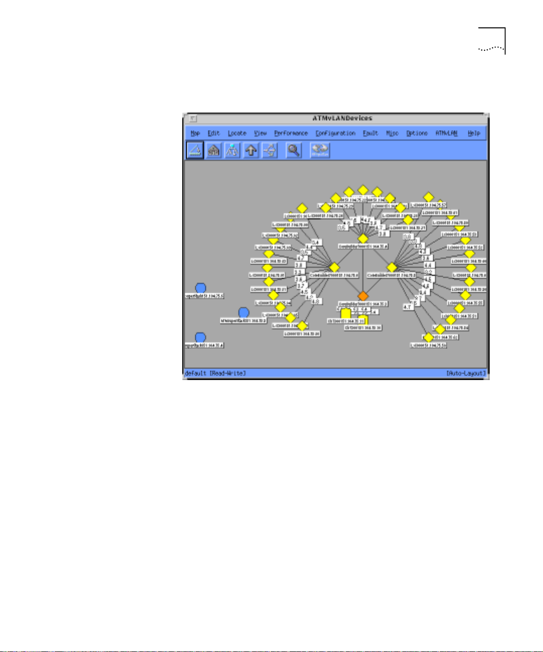
The ATM Device Manager map (see Figure 1-1), shows the physical
topology of the entire switched infrastructure in a single flat topology
map. The ATM Device Manager map provides the quickest access to all
ATM devices on the network. You also can select the devices graphic
Page 19
ATM and VLAN Management Maps 1-5
display to show the topolog y layout using the NMSetup t ool. See
Figure 1-35 for a description on setting the devices map layout.
Figure 1-1 ATM Device Manager Map
You can display a device-oriented view including device front panels,
device statistics and device parameters using the ATM Device Manager
menus and submaps.
Page 20
1-6 CHAPTER 1: ATM AND VLAN MANAGEMENT OVERVIEW
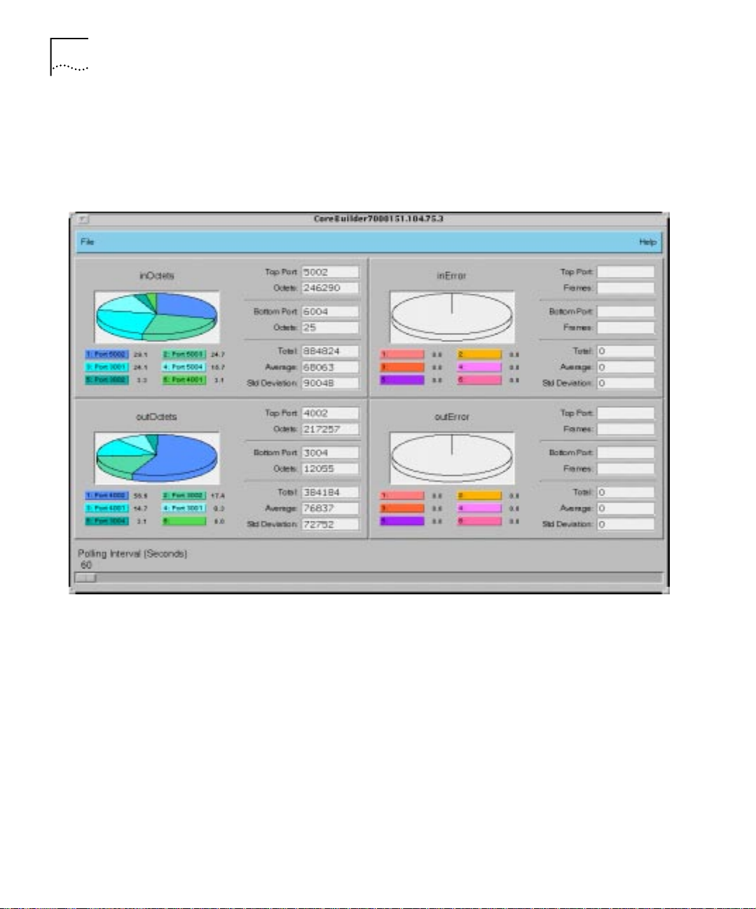
Figure 1-2 shows an example of the graph and statistics of a CoreBuilder
device. For example, to access teh device statistics window, select the
device in the AT MvLAN Devices window and then from the ATMvLAN
menu select Graph Assistant.
Figure 1-2 ATM Switch Graph Assistant Window
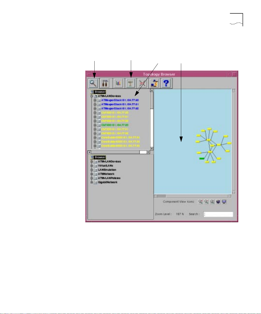
Figure 1-3 shows the hierarchy in the Topology Browser. To access the
A TM Devices m ap, doubl e click on the ATMvLAN Devices branch or select
Page 21
ATM and VLAN Management Maps 1-7
the branch and then select the Zoom icon. See page 1-27 for a
description of the Zo om ic o n.
Zoom icon Topology View
Cross Reference icon
Component View
Zoom icon
Figure 1-3 Access to the ATM Devices Map through the Topology Browser
To display the selected device in the Topology View, select the device in
the Component View and then select the Cross Reference icon.
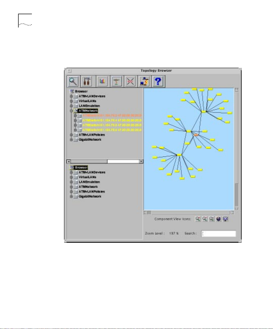
ATM Network Map The ATM Network map (see Figure 1-4) allows you to perform
management tasks on diff erent ATM devices,depend in g on thei r physi cal
connectivity. The ATM Network window displays a hierar chical switching
backbone of the network . Each ic on re pr esents a swi tching do main, such
as a central high-speed CoreBuilder ATM switch module that is connected
Page 22

1-8 CHAPTER 1: ATM AND VLAN MANAGEMENT OVERVIEW
to various ATM devices, such as a SuperStack II switch 2700 and other
CoreBuilder modules. The line s connecting the ATM switching domains
indicate the P-NNI (Private Netw ork to Network Interface) links between
them.
The ATM Network Map provides:
■ Displayof the connectivity between ATM switches (CoreBuilder 7000)
and ATM edge devices and end stations (SuperStack II Switch
2700/1000/3000, CoreBuilder 2500, CoreBuilder 5000, NETBuilder,
ATM adapter)
■ Identification of port numbers on the links between switches
■ Statistics on tr affic to a nd from different devices and t hrough specific
device ports
■ Tracing and modification of virtual circuits betw een devices
■ Selection of ATM end points to perform ATM path tracing
Figure 1-4 ATM Network Map Main Display
Page 23
ATM and VLAN Management Maps 1-9
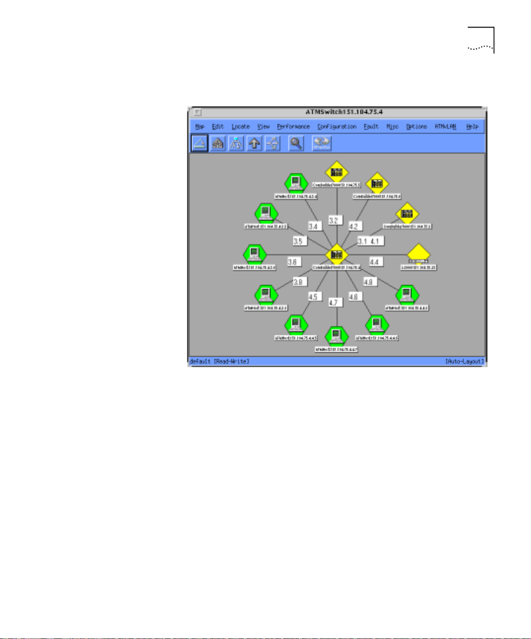
Figure 1-5 shows the ATM Switch map, which is an example of the
submap of the Network map.
Figure 1-5 ATM Switch Map
Page 24
1-10 CHAPTER 1: ATM AND VLAN MANAGEMENT OVERVIEW
Figure 1-6 shows the hierarchy in the Topology Browser from which you
can access the ATM Network map.
Figure 1-6 Access to the ATM Network Map through the Topology Browser
To display a selected switch in the Topology Browser , select a switch in the
Component View and then select the Cross Reference icon.
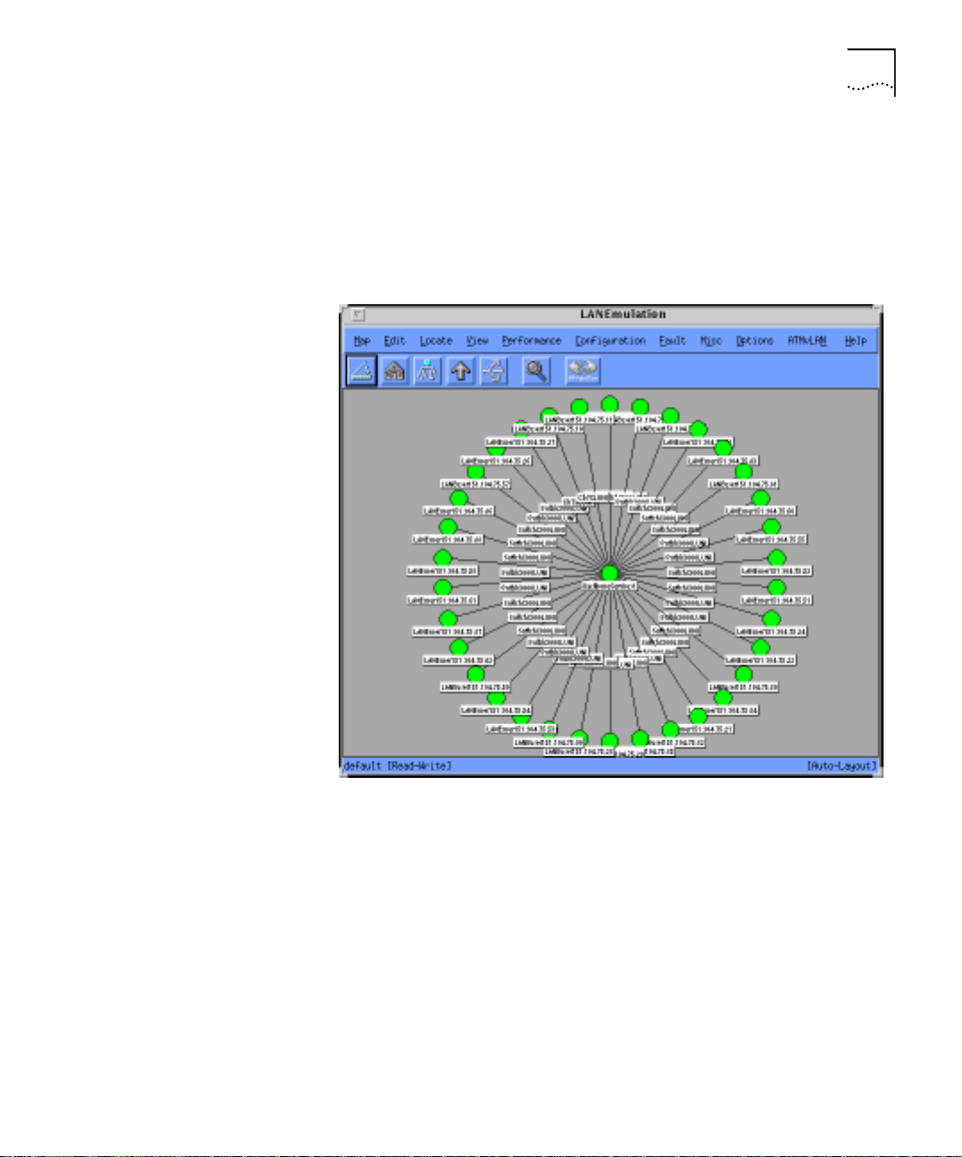
LAN Emulation Map The LAN Emulation map (see Figure 1-7), allows you to perform network
management tasks on the LAN Emulation clients and servers.
The LAN Emulation provides:
Page 25
ATM and VLAN Management Maps 1-11
■ ATM device display in the LAN emulation process
■ Display of the LECS, LES,and LEC port connectivity
■ Isolation of LEC, LES, and LECS faults
■ Mapping of ELANs to VL AN ports display
■ Monitoring of LANE services performance
Figure 1-7 LAN Emulation Map Main Display
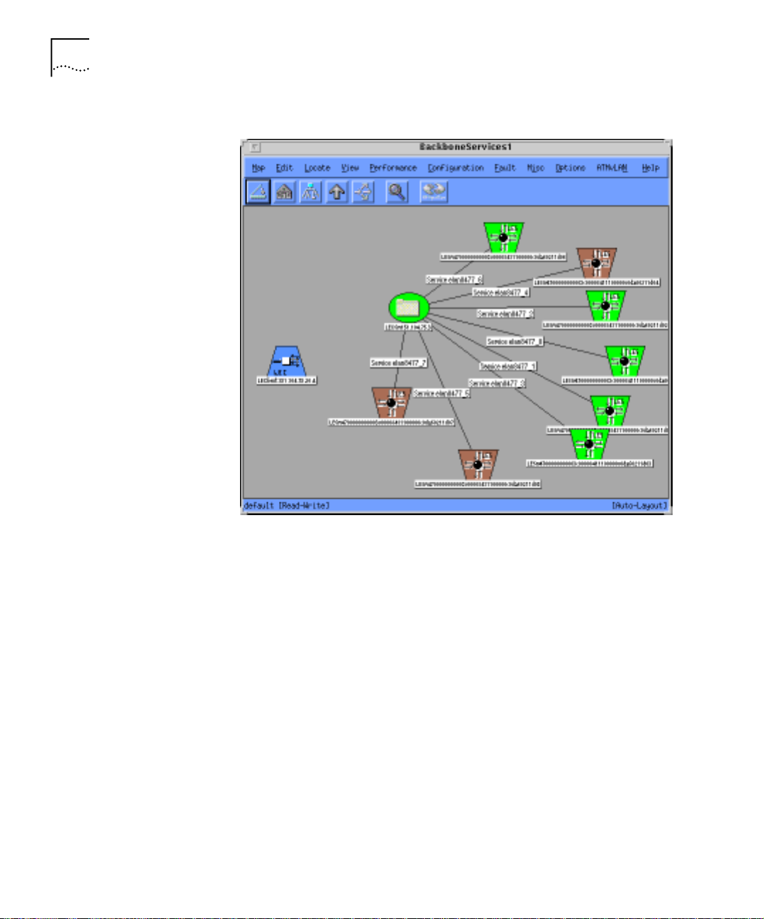
Figure 1-8 shows the Backbone and Serv ices window which is an
example of a submap of the LAN Emulation window. This window
displays different emulated LANs, each with the LECs connected to the
central LES. The window also shows the active and or enabled LEC Ss.
Page 26
1-12 CHAPTER 1: ATM AND VLAN MANAGEMENT OVERVIEW
Figure 1-8 LAN Emulation Submap/Backbone and Services Window
Page 27
ATM and VLAN Management Maps 1-13
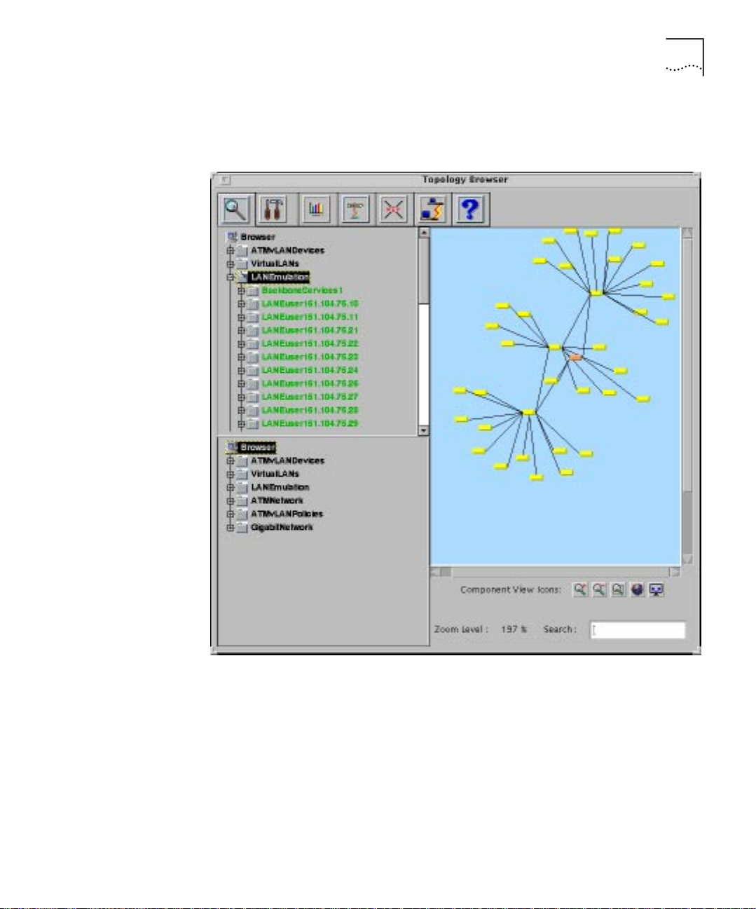
Figure 1-9 displays the hierarchy in the Topology Tool from which you can
access the LAN Emulation Map.
Figure 1-9 Access to the LAN Emulation Map using the Topology Tool
Component View
To display a LAN Emulation component in the Topology View, highlight
the component in the Component View and then select the Cross
Reference icon.
Page 28
1-14 CHAPTER 1: ATM AND VLAN MANAGEMENT OVERVIEW
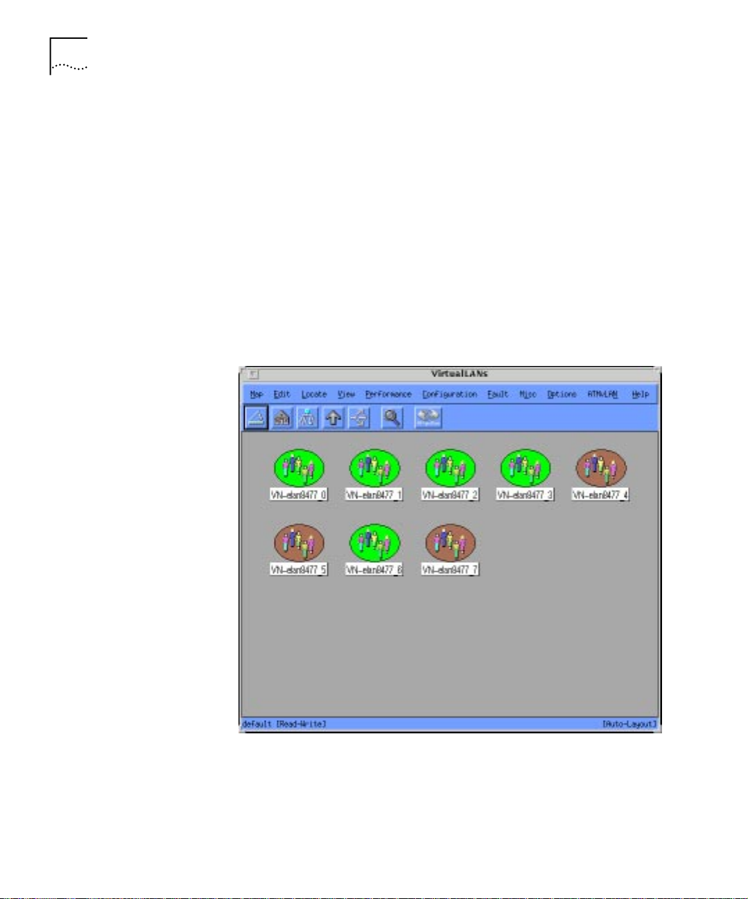
Virtual LANs Map
The Virtual LANs Map (see Figure 1-10), is used to manage the logical
connectivity of the end -user through the Virtual LANs. The Virtual LANs
maps provide view s of the connectivity between Ethernet/ATM ports to
the different VLANs. You use the Virtual LANs Map to manage ATM LAN
Emulation-based as well as legacy LAN encapsulated or tagged-based
VLANs.
The features of the Virtual LANs Map include:
■ Re-configuration of VLANs
■ Moving segments between VLANs, using simple mouse actions
■ Clarification of VLANs to physical ports ma p pin g
Figure 1-10 The Virtual LANs Map Main Display
Page 29
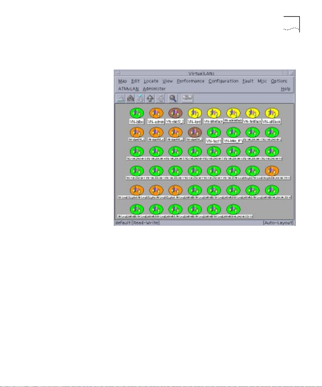
ATM and VLAN Management Maps 1-15
Figure 1-11 shows the Ethernet segments that belong to a selected
VLAN.
Figure 1-11 The Virtual LANs Submap Displaying Ethernet Segments
Page 30
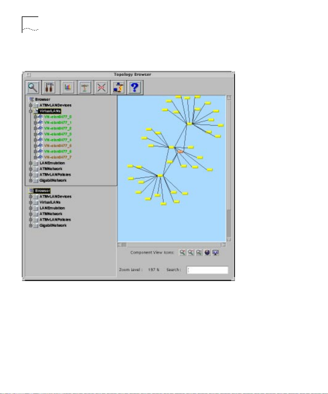
1-16 CHAPTER 1: ATM AND VLAN MANAGEMENT OVERVIEW
Figure 1-12 shows the hierar chy in t he Topology Tool from which you can
access the Virtual LANs Map.
ATM VLAN Policies
Map
Figure 1-12 Access to the Virtual LANs Map using the Topology Tool
Component View
To display components of the Virtual LANs map in the Topology View,
select the component in the Component View and then select th e Cross
Reference icon.
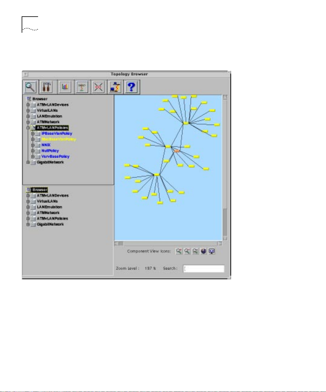
The A TM V LAN Poli cies Ma p (see Figu re 1-13), is use d for au tomating the
event of the logical con nectivit y of end-users or segm ents thr ough Virt ual
LANs, based on pred efined policies. The maps displays the various
Page 31

ATM and VLAN Management Maps 1-17
pre-defined policies that may be applied to network devices. The devices
that have policies applied are contained in the policy icon.
Note: The VLAN Policies may be used only with CoreBuilder 7000, Super
Stack II Switch 1000/3000//2700 with ATM downlinks.
Figure 1-13 The ATMvLAN Policies Map
Page 32
1-18 CHAPTER 1: ATM AND VLAN MANAGEMENT OVERVIEW
Figure 1-14 shows the hierar chy in t he Topology Tool from which you can
access the VLAN Policies Map.
ATM and VLAN
Gigabit Network Map
Figure 1-14 Access to the ATMvLAN Policies Map using the Topology Tool
To display a component of the Policies Map in th e Topology View, select
the component in the Component View and then select the Cross
Reference icon.
The ATM and VLAN Gigabit Netw ork Map shows the layer 2 topology of
Ethernet/Fast Eternity-based and in the future, Gigabit Ethernet-based
Page 33

ATM and VLAN Management Maps 1-19
network backbones. The Gigabit Ethernet topology views can be used to
identify Virtual LAN trunks, downlink connections within the network.
Figure 1-15 The ATM and VLAN Gigabit Network Map
Page 34

1-20 CHAPTER 1: ATM AND VLAN MANAGEMENT OVERVIEW
Figure 1-16 shows the hierar chy in t he Topology Tool from which you can
access the ATM and VLAN Gigabit Network Map.
ATM and VLAN Management Tools
Figure 1-16 Access to the ATM and VLAN Gigabit Network Map using the
Topology Tool
To display a component of the Gigabit Ethernet Map in the Topology
View, select the component in th e Component View and then select the
Cross Reference icon.
The ATM and VLAN Application Toolbar, see page 1-21, includes the
T ranscen d Topology Browser . You access the T ranscend Topology Borwser
Page 35

ATM and VLAN Management Tools 1-21
using the Topology icon. The Transcend Topology Browser can be used to
perform all the network management tasks that are performed using the
ATM and VLAN Management Maps and their assistants. The rest of the
application to ols are used for displaying graphs and statistics and to
locate parameters and other information on your net w ork.
The Topology, Locator, Bandwidth, Report, and Fast Setup tools are
accessible via a web browse r. You can access the ATM and VLAN
Management Tools from any station with a web browser, independent of
the network management platform.
To access the A TM and VLAN management tool s:
Open a web browser.
Enter the URL:
http://machine_ip_address/:7689/WebBase
The ATMvLAN
To ol ba r
The ATM and VLAN Manager Application Toolbar consists of the
following tools:
■ Topology
■ Bandwidth
■ Report
■ Locator
■ Users
■ Profile
■ Tasks
■ Fast Setup
■ NMSetup
To invoke an option in the ATMvLAN Application Toolbar, click on one of
the icons.
Page 36

1-22 CHAPTER 1: ATM AND VLAN MANAGEMENT OVERVIEW
The ATMvLAN
Application Toolb ar.
Icon Display Icon Name Description
Topology
Opens the Transcend Topology Browser.
The Topology Tool consists of the
Component View and Top ology Vie w. You
can perform most network mana gement
tasks using this tool. See “Topology Tool”
on page 1-23.
Bandwidth Opens the NNIx Browser and NNIx
Report Opens the NNIt Report Display with
Locator Opens the Locator Tool which is used to
Users Opens the Build UDB Tool that builds the
Profile Opens the VN Pro Tool that lists an
Tasks Opens the Sp ider Tool that displays the
topology maps. Allows you to display and
view traffic patterns on the network. See
“Bandwidth Tool” on page 1-28.
information about the NNI traffic in tabu lar
format. See “ Report Tool” on page 1-29.
search and locate the ATMvLAN databases.
See “Locator Tool” on page 1-30.
entire user’s database. See “Users Tool” on
page 1-31.
inventory of devices and VLANs on the
network. See “Profile Tool” on page 1-33.
current tasks on t he ne twork. See “Tasks
Tool” on page 1-36.
FSetup Opens the Fast Setup Wizard for the
CoreBuilder 7000. See “FSe tup Too l” on
page 1-36.
Page 37

ATM and VLAN Management Tools 1-23
Icon Display Icon Name Description
Opens the NMS Fast Setup Wizard to se tup
NMSetup
Figure 1-17 The ATMvLAN Toolbar
and configure t he NMS platform. See
“NMS Setup” on page 1-43.
Topology Tool
The Transcend Topology Browser, formerly called the Wizard Tool is
available as a part of t he TEM 4.2.2 Unix release.
The Topology Tool (see Figure 1-18), is designed to manage Virtual LANs
and switched networks and can be used as a stand-alone (open
management platform independent) graphical network management
tool. The Topology Tool provides a consolidated interface for performing
Page 38

1-24 CHAPTER 1: ATM AND VLAN MANAGEMENT OVERVIEW
various network management tasks requ ired t o manage Virtual LAN s and
switched network s.
Figure 1-18 The Transcend Topology Browser
In the absence of a management platform (such as HPOV etc.), this tool
can be used a the primary GUI for managing the switched networ k.
All management functions such as monitoring, con figuration, statistics
gathering etc. can be performed using this interface.
The Transcend Topology Browser is comprised of two sections. The
section on the left is the Component View and the section on the right is
the Topology View.
Page 39

ATM and VLAN Management Tools 1-25
The Topology View shows the layer 2 physical topology of la rge switch ed
infrastructures (net works with more than 500 Switches) in a single
hierarchy. For example, all the devices, such as ATM switches,
Fast-Ethernet Switches, and there corresponding edge devices, are
mapped.
The tree type Component View is hot linked to the Topology View and
allows for quick selection of infrastructure compone nts th at a re
dynamically highlighted on the topology map. This feature allows you to
select an entry in the Component View, and view the highlight ed
component in the Topology View using the Cross Reference icon.
For example, if you select a switch or an edge device fro m the ATMvLAN
Devices branch in the Component View, the selected switch is
highlighted in the Topology View. If you select a VLAN entry in the VLA N
branch, all the switches that belong to the VLAN are highlighted
The Component View has two windows for displaying the components.
The two windows allow for opening and viewing different branches at
the same time. For example, in the top window, a VLAN branch may be
opened displaying all t he VLANs. In the bottom window, a specific VLAN
branch may be selected, and the segments within the VLAN displayed.
When performing VLAN moves, segments may be selected from one
window (top or source), and the target VLAN may be selected from the
other window (bottom).
T raffic pattern overlays are planned for the future in the Component View
as the Topology View will be hot linked to the Bandwidth Tool.
The topology map includ es the following icons:
■ Zoom Out - This tool is used to magnify the topology map.
■ Zoom In - This tool is used to reduce the topology map.
■ Select Area - This t ool is used to select an area of the topology map.
Use this tool by cli cking on the icon and then defining a n area ( square)
on the topology map. The selected area is resized to fit the topology
map window. When used in conj unction with the Pan tool, you can
resize the selected area by resizing one of the rectangles handles using
MB1.
■ Pan - The tool opens up a display window that allows you to pan the
entire network.
Page 40

1-26 CHAPTER 1: ATM AND VLAN MANAGEMENT OVERVIEW
■ Refresh - This tool updates the network status.
The Topology Tool includes the fo llowing features:
■ Rearrange - You can rearrange the components for display by
dragging them on the Component View to the desired location.
■ Search - This feature allows you to enter an IP address and locate the
device on the Topology View.
■ Highlight - The Component View, in conjunction with the Cross
Reference Tool highlights the component selected in the Topology
View.
■ Identify - Use this feature to identify the device IP Address and its
name. You use the i dentify feature by clicking with the right mouse
button on the Topology View.
■ Display Front Panel - The feature is the same as the Zoom Physical
feature in the ATM and VLAN Management application. You can
display device front panels by double clicking on the device in the
Topology View.
The Component View reflects the status of all the components that are
being actively p olled by a di stribu ted po lli ng agen t (me dp). For customer s
that do not want to use the platform maps, HPOV, Netview or SunNet
Manager, the Transcend Topology Browser may be us ed as the main
console.
For distributed viewing capability, the Topology Tool can be
accessed via a web browser.
You must upgrade Netscape to Version 4.03 with JDK1.1 support.
Upgrading to Netscape 4.03 is insufficient to run the web-based ATM
VLAN software. You must have the JDK 1.1 support for the software to
run properly.
The JDK software may be downloaded from the JAVA site currently at:
http://developer.netscape.com/software/index.html?content=jdk/downlo
ad.html
Page 41

Topology Tool
ATMvLAN Objects
Toolbar
ATM and VLAN Management Tools 1-27
Icon Display Icon Name Description
Zoom Zooms in on the selected branc h. Performs
Configuration
Assistant
Graph
Assistant
Cross
Reference
Move Opens up the Configuration window for
the same zoom action as when you select
an icon and then select ATMvLAN - >
Zoom Physical in the ATM and VLAN
management maps.
Opens up the Configuration window for
the selected branch. Performs the same
action as when you se lect an icon a nd then
select ATMvLAN - > Configuration
Assistant in the ATM and VLAN
management maps.
Opens up the Graph window for the
selected branch. Performs the same action
as when you select an icon and then select
ATMvLAN -> Graph Assistant in the ATM
and VLAN management maps.
Displays the comp one nt hig hli ghted in the
LANScape Browser in the LANScape
topology map.
the selected branch. Performs the same
action as when you se lect an icon a nd then
select ATMvLAN - > Move in the ATM and
VLAN managemen t maps.
Page 42

1-28 CHAPTER 1: ATM AND VLAN MANAGEMENT OVERVIEW
Icon Display Icon Name Description
Path Assistant Opens up the Path window for the
selected branches. Performs the same
action as when you select two icons and
then select ATMvLAN -> Path Assistant in
the ATM and VLAN management maps.
Help Opens up the on-line Help files to help you
use the ATM and VLAN Management
application,
Bandwidth Tool
The Bandwidth icon opens the Network Node Interface Traffic Tool, NNIx,
(see Figure 1-19), and displays all the ATM switches and traffic patterns
on the NNI and UNI levels of switches. The NNIx Browser and Maps
provide a graphical display of the network link utilization. You can also
display the percentage of traffic on the network using the NNIx Maps.
The Bandwidth Tool is organized based on enhanced Interswitch Interim
Signalling Protocol (IISP) address hierarchy. This tool is used to log the
traffic information to a file, so that historical network-wide NNI link level
data can be gathered and displayed. The Bandwidth tool is also used to
graphically display errors on NNI links across the networks.
See Chapter 7 for a detailed description of the Bandwidth Tool.
Page 43

ATM and VLAN Management Tools 1-29
Figure 1-19 The Network Node Interface Traffic Tools
Report Tool
The Report icon opens the Ne twork Node Inte rface Tabular Tool, NNIt, see
Figure 1-20, and is identical to the Bandwidth Tool, except that the
information is displayed in a report (tabular) format. The devices that are
linked are listed in a directional table, left to right or right to left. The
percentage of tra ff ic and numb er of oct ets p er secon d goin g thr ough t he
switches is also listed in the table.
Page 44

1-30 CHAPTER 1: ATM AND VLAN MANAGEMENT OVERVIEW
Figure 1-20 The Network Node Interface Tabular Tool
Locator Tool
The Locator Tool, (see Figure 1-21) functions as a search and modification
tool to the ATM and VLAN application’s databases. These databases are
built using other to ols. For example , the MAC VDB data base is built using
the Build UDB Tool. The Manual Discovery database is built using the
Manual Discovery Setup. See “Configuring Manual Device Disco very” on
page 4-1. The VL AN Aliases a nd Colors d atabase ar e bu ilt using t he VLAN
Aliases and Colors Setup. See the d escrip tion of setti ng VLAN alia ses and
colors on page 4-20. The Locator sear ches these databases and allows
you to modify parameters within them.
Page 45

ATM and VLAN Management Tools 1-31
The Locator Tool uses a search string that is color-coded and displays all
other parameters for the selected string in the bottom portion of the
dialog box.
Figure 1-21 The Locator Tool
Users Tool
The Users T ool opens the Build UDB tool, see Figure 1-22, is used to build
a parameter database for st oring all the information related to MAC
addresses in the network. The Users Tool performs an inventory of the
existing network, automatically discovers the MAC addresses that exist
and their respective locations (device, port) and their current VLAN
mapping. The parameter database populated by the Build UDB tool may
be modified manually to change VLAN mapping. Use the Locator Tool to
edit the database. Devices that enforce the MAC based Automatic VLAN
configuration policy will query this database to resolve MAC address to
VLAN mapping.
Page 46

1-32 CHAPTER 1: ATM AND VLAN MANAGEMENT OVERVIEW
Since the Build UDB Tool requires lots of CPU as well as generates a lot of
SNMP traffic, we r e commend tha t you use this tool du ring peri ods of low
network activity.
Figure 1-22 The Build UDB Tool
Page 47

ATM and VLAN Management Tools 1-33
Profile Tool
The Profile icon opens the VnPro Tool that lists all the network devices
and their associated V LANs. Thi s tool provides a compr ehensi ve inve ntory
of all the VLANs in the network.
Figure 1-23 The VnPro Tool
The top section displays the VLAN Configuration. The devices, and the
associated port numbers an d VLAN names are displayed.
To use the VnPro Tool:
Page 48

1-34 CHAPTER 1: ATM AND VLAN MANAGEMENT OVERVIEW
Highlight a line in the di splay.The bottom section displays the informati on
for the selected line. The bottom section of the VnPro Tool is used for
display purpo s es only.
The Options menu allows you to perform the following:
■ Move
■ Refresh
■ Save As
■ Quit
The Move option is no t im pl e m en te d in this relea s e .
The Refresh option allows you to update the VLAN Co nf ig ura ti on table
for the latest device and VLAN information.
The Save As option saves the VnPro information to file. The information
can be saved as text or to a file capable of being opened in Excel.
Figure 1-24 VnPRo Save As dialog box
Page 49

ATM and VLAN Management Tools 1-35
The Quit option exits the VnPro Tool.
A VLAN may be defined without ports when the VLAN is defined in the
edge device (Vbridge is allocated) however, the VLAN ports are not
associated with the VLAN at this point.
Page 50

1-36 CHAPTER 1: ATM AND VLAN MANAGEMENT OVERVIEW
Tasks Tool
The Tasks icon opens the Spider Tool (see Figure 1-25), that provides a
graphical display of the underlying distributed processes in the ATM and
VLAN Management application. This is only a graphical display tool used
to illustrate the underlying network-wide configuration
infrastructure/engines and their logical layout. This diagnostic tool
displays the active processes and the devices they are applied upon.
Figure 1-25 The Spider Tool
FSetup Tool
The Fast Setup Tool is a wizard that allows you to configure the
CoreBuilder 7000 through the ATM and VLAN Management application.
It is a step by step procedure that prompts you to enter the CB7000
parameters required for network man agement.
To use the Fast Setup Tool:
Click on the FSetup icon in the ATMvLAN Toolbar. The CoreBuilder 7000
first Fast Setup Wizard Pane l is displayed. See Figure 1-26.
Page 51

Figure 1-26 Fast Setup Wizard Step 1
ATM and VLAN Management Tools 1-37
To select the CoreBuilder 7000
1 Enter the CoreBuil der 7000 IP A ddr ess or select an add ress f ro m the dr op
down menu.
2 SNMP Community String.
3 Click Next. Panel 2 is displayed.
Page 52

1-38 CHAPTER 1: ATM AND VLAN MANAGEMENT OVERVIEW
Figure 1-27 Fast Setup Wizard Step 2
1 Enter the Network prefix in the General Parameters wizard panel.
2 Click Next. Panel 3 is displayed.
Page 53

Figure 1-28 Fast Setup Wizard Step 3
ATM and VLAN Management Tools 1-39
1 Select whether you want the Resident LECS Service to be enabled on the
selected CoreBu il der. Toggling it o n, immedi at ely e nab les the LES Servi ce.
The resident L ECS Service does not need to be enabl ed for the LES Service
to be enabled.
2 Enter the User part of the Resident LECS.
3 Click Next. Panel 4 is displayed.
Page 54

1-40 CHAPTER 1: ATM AND VLAN MANAGEMENT OVERVIEW
Figure 1-29 Fast Setup Wizard Step 4
1 Enter the prefix and user-part addresses of the Active LECS table.
2 Click Next. Panel 5 is displayed.
Page 55

Figure 1-30 Fast Setup Wizard Step 5
ATM and VLAN Management Tools 1-41
1 Enter the maximum number of N NI hops.
2 Select the port settings.
The port settings may be either UNI, NNI or GW.
Click Next. Panel 6 is displayed.
Page 56

1-42 CHAPTER 1: ATM AND VLAN MANAGEMENT OVERVIEW
Figure 1-31 Fast Setup Wizard Step 6
1 Enter the Switch IP address, subnet mask and default gateway.
2 Enter the NMS address.
Figure 1-32 Fast Setup Final panel
Page 57

ATM and VLAN Management Tools 1-43
This panel is to review your settings. Use the scroll bar to view your
settings. Click Prev to change settings. Click Finish to apply the settings.
NMS Setup
The ATMvLAN NMSetup Wizard allows you to setup the NMS by
following the instructions on the screen.
To use the NMSetup Tool:
Click on the NMSetup icon in the ATMvLAN Toolbar. The NMSe tup
Wizard Panel is displayed. See Figure 1-33.
Figure 1-33 NMS Setup Step 1
Define the pollers and the devices that each poller is responsible for in the
Delegation MedP panel. Click Next. Step 2 is displayed. See Figure 1-34.
Page 58

1-44 CHAPTER 1: ATM AND VLAN MANAGEMENT OVERVIEW
Figure 1-34 NMS Setup Step 2 Delegation PDP
Enter the Device Set and the Target Poller and click Next. Setup 3 is
displayed. See Figure 1-35
Page 59

ATM and VLAN Management Tools 1-45
.
Figure 1-35 NMS Setup Step 3 Platform options
This panel allows you to enable platform options. You can save the
graphic display of the OpenView Maps by toggling persistent on.
If Manual Device Discovery is not toggled on, the application will discover
from the platform database. When to gg led on, the appli cati on will rely
on manual popul a tio n of th e de v ice da tab a s e .
Click Next. Step 4 is displayed as in Figure 1-36.
Page 60

1-46 CHAPTER 1: ATM AND VLAN MANAGEMENT OVERVIEW
Figure 1-36 NMS Setup Step 4 Advanced Options
Define the number of seconds that the application will wait for the
network to settle down before it start the LES failure verification process.
This number could be tune d down to about 120 seconds if the re are no
redundant switch engines in the network. If there are redundant switch
engines, the default number should be used.
Enter the fields in the Ad vanced options panel and click next. Step 5 is
displayed. See Fig u re 1-37.
Page 61

ATM and VLAN Management Tools 1-47
Figure 1-37 NMS Setup Step 5 Locator
Page 62

1-48 CHAPTER 1: ATM AND VLAN MANAGEMENT OVERVIEW
Toggle on the appropriate fields and click Next. The final panel is
displayed showing your final NMS Setup settings. See
ATM and VLAN Management Assistants
Configuration
Assistants
Figure 1-38 NMS Final Panel Review Settings
ATM and VLAN Management Assistants are launched from the ATM
VLAN Maps and Tools. These assistants are used to perform various
functions such as configuration of services, statistics gathering,
troubleshooting and other network tasks.
The configuration assi stants are used to configure the network elements
in the management maps. ATM and VLAN Management Assistants are
launched from maps or tools.
The Configuration Assistants include:
■ LECS Redundancy
■ LECS Database Configuration and Synchronization
■ LES/BUS Redundancy Setup and Activation
■ VLAN Aliases and Colors Setup
See Chapter 4 for a more detailed description of these assistants.
Page 63

CONFIGURING AND LAUNCHING
2
THE ATM AND VLAN MANAGER
This chapter contains the following topics:
■ Configuring SNMP SmartAgents on Devices
■ Device Configuration for VLANs in ATM Networks
■ Device Configuration for VLANS in Non-ATM Networks
■ Starting Up the ATM and VLAN Manager
■ Device Discovery
All 3Com devices in cludi ng C oreB ui lde r 7000 , Supe rS tack I I Swi tch 27 00 ,
SuperStack II Switch 1000/3000, SuperStack II Desktop Switch,
CoreBuilder 7X00, NetBuilder II, CoreBuilder 4000, SuperStack II Switch
2000, CoreBuilder 2500 and CoreBuilder 5000 Fast/Switch Modules may
be managed through th e A TM and V LAN Management tools. Plea se refer
to the specific device Setup Manual for device initialization and setup
instructions.
NMSetup The NMSetup Tool located in the ATMvLAN Toolbar, opens the NMSetup
wizard that allows you to set all the NMS configuration parameters and
values in a step by step procedure.
NMSetup
To use the NMSetup Tool:
Page 64

2-2 CHAPTER 2: CONFIGURING AND LAUNCHING THE ATM AND VLAN MANAGER
Click on the NMSetup icon in the ATMvLAN Toolbar. The NMSetup
Wizard Panel is displayed. See Figure 2-1.
Configuring SNMP SmartAgents on Devices
Figure 2-1 NMSetup Step 1
For a detailed description of the NMSetup Tool see page 1-43.
The NMS performs physical l ayer manage ment usi ng the SNMP. The NMS
polls agents for status, configurati on and ne two rk traffic informatio n .
The first step in initializing the network for management is to configure
the SNMP SmartAgents in the 3Com ATM and VLAN devices.
To configure the SNMP SmartAgents on Devices:
1 Determine the manage ment IP subne t and IP addr esses to be used for the
ATM devices and the Transcend ATM and VLAN Manager Stat ion.
2 Configure the IP address and default gateway in each ATM switch unit.
See the device Installation and Setup Guide for the swit ches you are
using.
It is recommended that all the ATM and VLAN devices be configured as
members of the same subnet as the Network Management Station
Page 65

Configuring SNMP SmartAgents on Devices 2-3
(NMS). This allows the N MS to access t hese d evi ces dir e ctly over th e ATM
network instead of goin g across router s.
3 Configure the IP address, and default gateway of Bridge 0 in each of the
edge device units. See the device Installation and Setup Guide for the
devices you are using.
Configuring SNMP
SmartAgents and
Parameters
Community names set on the NMS must correspond with community
names set on the agent(s). Conf igure the SNMP gener ic parameters on
the ATM and VLAN Network Manager as fol lo ws:
1 Configure the default SNMP Community Setting on the Network
Management Platform according to Table 2-1. See the Network
Management Platform Administration Manual.
Table 2-1 Configuring SNMP Community Settings
Device
CoreBuilder 7000
CoreBuilder 7X00
SuperStack II Switch 2700
SuperStack II Switch
1000/3000/Desktop Switch
SuperStack II Switch 2000 Private
CoreBuilder 2500/6000
CoreBuilder 5000 Switch
Module
SuperStack II Switch 2000 TRSecurity
NetBuilder II Public
CoreBuilder 4000 Public
SNMP Community
Setting
Private
Security
Public
If default SNMP Commun iti es a re ch ang ed in t he devic es, you must en ter
the new communities as well.
2 Verify the IP/SNMP connectivity using the IP Map.
All devices in the management subnet should appear on the IP Map of
the management platform. The IP connectivity is verified by the
appearance of the IP address. The SNMP connectivity is verified by the
appearance of the device icon. The process of esta blishing connectivity
should take about 5 minutes.
Page 66

2-4 CHAPTER 2: CONFIGURING AND LAUNCHING THE ATM AND VLAN MANAGER
CAUTION: Do not start the ATM and VLAN Network Manager until all
the ATM and VLAN devices have been discovered and appear in the IP
Map of the management platform.
Setting Up for
Distributed Polling
Polling in SNMP management is the activity whereby the NMS
interrogates/polls individual nodes on the networ k for their current
status. It is one if the most important sources of network management
control for traffic on the network.
The ATM and VLAN Management application ma intains the status and
state of all the logical and physical components of the network. You
cannot rely on the platform poller alone (such as HPOV SNMP Poller)
which only maintains the “ping” status of the network when using the
application. T he ATM and VLAN Management application us es a
platform-independent poller call ed the Mediation Poller or Medp to
actively maintain the status of all the components it is monitoring.
Starting the Poller Locally
In small networks cons isting of le ss than a 100 n etwork devi ces (ATM and
Non-ATM switches), a single central poller is adequate for polling the
network and maint aining the stat e of t he logi cal an d physic al net work. In
these types of netwo rks, the Me diation Pol ler can r eside on t he NMS. The
default configuration installs the mediation poller when the ATM and
VLAN Management application is installed. The poller is initialized and
activated along with ot her network management pla tform processes.
Starting the Poller on Multiple Distributed Machines
When using the application to manage a larger network, consisting of
many network devices, or when the network is managed over a wide
area, it is possible to distribute the polling.
Distributing polling onto more than one machine has several advantages.
The advantages are:
■ Localizes polling in remote sites so as not to send polling traffic on
WAN links.
■ Distributes the polling load onto several machines to get better polling
performance and SNMP traffic distribution.
■ Frees up CPU resources on the central management station, thus
providing better cons ol e pe rfo rm a nc e .
Page 67

Configuring SNMP SmartAgents on Devices 2-5
The following ste ps mu st be foll o w ed wh e n in sta lling distributed po ll ers:
1 Install the Transcend ATM and VLAN Management application on the
central machine on top of an open management platform such a HPOV.
In a distributed polling environment, this machine is the Central Viewing
Station or Central Ma na gement Console
or
install the Transcend ATM and VLAN Management application as a
stand-alone application, on other U nix machines (Solaris, AIX or HPUX).
An open management platform is not requ ired. In a distributed polling
environment these machines are referred to as polling stations or pollers.
These machines do not require an open management platform such as
HPOV installed on them.
2 On the polling station, start the polling process:
a Change Directory to /usr/NCDNMS/make/
b Execute the file “medp.”
It is advised to include these steps in the boot configuration of the polling
station so that the y ar e executed a utomaticall y when th e polling station i s
booted up.
3 Configure the ATM and VLAN Management a pplication on the central
management station to recognize the distri buted pollers and delegate
polling responsibilities to each poller.
Before starting the application , ed it the fol lo w in g file :
/usr/NCDNMS/runtim e/cn f/m ed ia tio n d.cnf
Each line in the /usr/NCDN M S/ run ti me / cn f/m e d iatio n d. c nf co n s ists of
three fields, each separated by a colon. The upper lines in the files take
priority over the lower lines.
This customization of this file can be performed using the NMS
Setup Wizard.
The first field is the range of the IP addresses tha t devices will be polled
from. The second field is the poller IP address. The third field represents
the socket port number communication port. The default number for the
socket port is 1161
Page 68

2-6 CHAPTER 2: CONFIGURING AND LAUNCHING THE ATM AND VLAN MANAGER
An Example of Distributed Polling.
100.200.100.170-180:100.200.100.78:1 161
100.200.100.*:100.200.100.79:1161
100.*.*.*:100.200.100.77:116 1
*.*.*.*:127.0.0.1:1161
Figure 2-2 A Listing of Contents from the
C:\TranscendNT\ATMvLAN\runtime\cnf\mediationd.cnf
Line one displays th e ran ge o f I P ad dr e sses (IP add r ess 100.2 00. 100) wi th
their last addr ess field, address ending in numbers between 170 through
180, polled to IP address 100.200.100.78, poller number1.
A hyphen should be used to indicate a range.
Line two displays all oth er IP addresses in subnet 10 0.200.100.*, are
polled to IP address 100.200.100.79, poller number 2.
A * should be used to indicate a wildcard.
Line three displays th at all o ther IP add ress in subnet ,100.*.*.*, are polled
to IP address 100.200.100.77, poller number 3.
Line four displays that all other address in the netw ork are polled to
127.0.0.1, poller number 4 which represents the poller located on the
local machine.
Be certain that the last entry in the mediation d.cnf file contains a global
subnet (*.*.*.*) in the first field to ensure that all nodes in the network
are assigned to a poller.
Page 69

Device Configuration for VLANs in ATM Networks 2-7
Device Configuration for VLANs in ATM Networks
CoreBuilder 7000
ATM Switch
Configuration
A Virtual LAN is logical port group spanning a single device or multiple
devices on a network forming a single broadcast or flooding domain.
When LAN Emulation protocols are used to create broad c ast domains
over ATM-based infrastructures, these broadcast domains are also
commonly known as Emulated LANs or ELANs. Each Emulated LAN is
serviced by a single LE S (LAN Emulat ion Serv er) and single BUS (Br oad cast
Unknown Server). Endstations or network devices that join a common
Emulated LAN are said to be in a single ELAN or VLAN . These endsta tions
communicate with the LAN Emulati on Servi ces (LES/B US) via anot her LAN
Emulation entity called a LAN Emulation Client (LEC).
To build and manage ATM/LAN Emulation-based Virtual LANs, the LAN
Emulation Services and Clients must first be manually configured into
their respective default states via device consoles or a local management
interface. Only after they are configured, can you use the ATM and VLAN
Management application to manage and manipulate the environment.
The CoreBuilder 7000 ATM Switch supports the LAN Emulation Services
(LES/BUS/LECS). Depending on the number of Emulated LANs that need
to be created, LANE services must be enabled on one or more
CoreBuilder 7000 switches in the networ k. You can use the CB7000 Fast
Setup tool to configure the CB7000 through the ATMvLAN Toolbar. See
“The CB7000 Fast Setup Tool” on page 2-8.
The following guidelines should be followed when enabling LAN
Emulation Services on the CoreBuilder 7000.
1 When there are multiple CoreBuilder 7000s, the LAN Emulation Serv ices
must be distributed amongst all the core switches.
For example, if 10 Emulated LANS are require d and the network is
comprised of 5 Cor eBuilde r 7000 s in the cor e of the net work, you sh ould
distribute the LANE Services on all the core switches.
All LANE services should be enabled on all the core switches. Since each
CoreBuilder 7000 suppo rts 16 LES/BU S pairs, so me of these LES/BUS pai rs
may be configure d as prim ary LAN E server s of an ELAN and the ot he rs as
backup LANE Servers for the primary LES/BUS pair. See Chapter 4.
2 When there are multiple CoreBuilder 7000s, the LAN Emulation
Configuration Server (LECS) may be enabled on multiple switches. Up to
5 LECSs may be configured as active LECSs in the netw ork . You should
enable LECSs on some of the core switches in the network.
Page 70

2-8 CHAPTER 2: CONFIGURING AND LAUNCHING THE ATM AND VLAN MANAGER
3 The Network Management Station should be connected directly to the
switch running the primary LECS. This will ensure that the NMS always
has access to the LECS so that it can enable the backup LES when the
primary LES fails. See “Description of LES/BUS Redundancy” on page
4-10.
The CB7000 Fast Setup Tool
This CB700 Fast Setup icon opens a wizard that allo ws to configure the
CoreBuilder 7000.
To use the Fast Setup Tool.
Click on the FSetup icon in the ATMvLAN Toolbar. Step by step
procedures are displayed that allow you to configure the CB7000.
ATM Edge Device
Configuration
A TM edge devices such as Super Stack II Switch 2700, CoreBuilder 7200,
Switch 1000, CoreBuilder 5000 Switch Modules etc., provide the legacy
LAN-to- ATM integration. Some of these edge devices need to be
pre-configured to enable the LAN Emulation Clients within them.
Typically, this involves configuring t he local bridge groups within the
devices and their corresponding LECs. Please refer to the appropriate
device configuration manuals for information on VLAN/ELAN
configuration of these devices.
Page 71

Device Configuration for VLANS in Non-ATM Networks 2-9
Device Configuration for VLANS in Non-ATM Networks
Virtual LANs in non- ATM (Fast Ethernet) environments are created by
using Layer 2 encap sul at ion o r Tagging as a means to create broad cast or
flooding domains. Ports that are common to multiple Virtual LANs are
known as Virtual LAN Trunks (VLT). Switch 1000/3000s and Core Builder
5000 Fast Module s supp o rt this fe ature. VLTs m us t be co n fig ured on the
switches prior to using the ATM and VLAN application to manipulate the
VLT-based VLANS. Please refer to the Switch 1000/3000/CoreBuilder
5000 Fast Module configuration manuals for information on VLT-based
Virtual LANs.
Page 72

2-10 CHAPTER 2: CONFIGURING AND LAUNCHING THE ATM AND VLAN MANAGER
Starting Up the ATM and VLAN Manager
Setting Up and
Customizing the ATM
and VLAN
Management
Application
This section describes the star t-up procedure for the ATM and VLAN
Management application for the HPOV/OVW platform:
Before you begin to use the ATM and VLAN Management application
there are several tasks that you should perform to setup and customize
the ATM and VLAN Management application. They are as follows:
1 Login to the UNIX workstation and start the OVW. See “Log in to the
UNIX Workstat ion and Start the OVW” on page 2-10.
2 Discover devices via the OpenView IP Map. See “Disco ver devices via the
HP OpenView IP Map” on page 2-10.
3 V erif y tha t you n etwor k i s up a nd ru nni ng . Se e “Verify that your network
is up and running.” on page 2-11.
4 Customize the VLAN colors and aliases. See “Customize the VLAN colors
and aliases.” on pag e 2-11.
5 Customize some of the other application configuration files using the
NMSetup Wizard. See “Custo mizing the Appl icat ion Co nfigur ation Files”
on page 2-12.
6 Restart the ATM and VLAN Management applic ation.
Login to the UNIX Workstation and Start the OVW
From the HPOV Root Window select ATMvLAN and then select Load
Transcend ATMvLAN Maps.
After a few seconds, icons representing the six ATM and VLAN
Management maps appear in the Root window. The ATMvLAN Toolbar
and the Virtual LANs and LAN Emulation windows appear.
Discover devices via the HP OpenVi ew IP Map
Ping devices if they don’t appear in the IP map. Start the ATM and VLAN
Management applicat ion only after all the devices are discovered by
HPOV and are displa yed in the IP map.
If you encounter problems discovering devices from the HPOV platform
database, or if you want to setup the applicat ion to ignore t he platform
Page 73

Starting Up the ATM and VLAN Manager 2-11
discovery database, you can manually discover devices using the Manual
Device Discovery Assistant. See “Using the Manual Device Discovery
Assistant” on page 4-2.
Verify that your network is up and running.
As the application begins, it is modeling (understanding the logical and
physical structure)
the ATMvLAN network. The length of this process
depends on the size of the net work. For larger networks, it may take up
to 15 minutes for your maps to be activated.
To check that the network modeling process is complete open the LAN
Emulation Map and verify that all of the icon colo rs ha v e cha n ge d from
blue to yellow, green or red.
Common Startup Problems
If the root ic ons don’t change color from blue, it may be because either
the MEDP or PDP task s are not runn in g .
There ar e two way s to che ck tha t the ME DP and PD P process are r unnin g
on OVW or NetView:
■ use the ovstatus command
■ use the ps command
The ps command is used for the Su nNet Manager to check if the
processes are running.
Customize the VLAN colors and aliases.
Customizing the VLAN aliases and colors enables the ATMvLAN device
view windows to show what VLANS each port is assigned to. If you do
Page 74

2-12 CHAPTER 2: CONFIGURING AND LAUNCHING THE ATM AND VLAN MANAGER
not customize the colors and alias settings, device view VLAN moves can
not be applied.
1 Select the Virtual LANs icon and then select the Configuration Assistant
icon. This displays the Virtual LANs configuration window.
Customizing the
Application
Configuration Files
Figure 2-3 Virtual LANs Configuration Assistant
2 Create the VLAN alias and color mapping.
To select a VLAN aliases and associated names:
a Select the VLAN ID from the pop-up list.
b Type in th e new VLAN Na m e.
c Select the VLAN color from the pop-up list.
d Click Add
e Click Apply to save all the u pdate d VLAN name s and a liases. C lose th e
window by selecting File - > Close. The changes are applied only after
the ATMvLAN Management application is unloaded and re-loaded.
There are several settings that can be custom ized by modify ing the values
in files stored in the C:\usr\TranscendNT\ATMvLAN\runtime\cnf and
C:\usr\TranscendNT\ATMvLAN\runtime\dat directories. These settings
affect various features of the ATM and VLAN Management application
and can make your ATM network easier to manage. Once changed, the
application needs to be unloaded and reloaded for them to be applied.
Page 75

Starting Up the ATM and VLAN Manager 2-13
These files and directories must be back ed-up be for e inst alli ng/upgrad ing
to a newer release of the ATM and VLAN Management application.
The A TMvLAN NMSetup Wizard allows you to modif y these configuration
files. This customization will take effect upon restarting t he application
after the customization is performed using the customization Wizard.
Table 2-2 lists the names of the some files that you can customize using
the NMSetup Wizard.
Table 2-2 ATMvLAN Customization Files
Filename Description
mediationd.cnf T his file has the inform ation about al l the distributed p ollers
noplatdis.cnf
127.0.0.1.ppp
numcpsrvs.cnf The number set in this file (1-16) determ ines the num ber of
protimeout.cnf The number in this file determines the number of seconds
VnRgb.dat Is the file where the VLAN aliases and color information is
and the devices th at ea ch po ller i s resp onsible . The setup o f
distributed pollers is explained in the See “Setting Up for
Distributed Polling” on page 2-4.
This file is customized by the Setup Wizard.
If this file exists, the application will not discover from the
platform database. It will rely on manual population of the
device database
(C:\TranscendNT\ATMvLAN\runtime\sav\127 .0.0.1.ppp)
using the Manual Discovery Tool. The default is to use
platform discovery and this file by default is
noplatdis.cnf.bak
This file is customized by the Setup Wizard
LESs displayed in the maps. So if you are only using 2
LES/CoreBuilder, set the number to 2 and only the first 2
LESs of the CoreBuilder are shown in the maps.
This file is not customized by the Setup Wizard.
that the application will wait for the netwo rk to settle down
before it start the LES failure verification process. This
number could be tuned down to about 120 seconds if
there are not redundant sw itch engine s in the network . See
Chapter 4 for a more detailed description. If there are
redundant switch engines, the default number should be
used.
This file is customized by the Setup Wizard.
saved after the aliases and colors are set. This file must be
saved when the application is upgraded to a newer release.
This files is customized by using the VLAN Aliases and
Colors setup assistant.
Page 76

2-14 CHAPTER 2: CONFIGURING AND LAUNCHING THE ATM AND VLAN MANAGER
Table 2-2 ATMvLAN Customization Files
Filename Description
Spider.cnf This file format is similar to the mediationd.cnf file. The
contents of the file define the location of the distributed
proxy smart Agents (pdp). It can either point to the local
host or a remote proxy agent. You can assign different
proxy agent to different IP address ranges. These proxy
smart agents are used for Policy based VLAN configuration,
data collection for NNIx tool, MAC address inventory etc.
#
# NCD JAVA Configuration File
#
# PDP List
# Devices: PDP ip: PDP port
*.*.*.*:127.0.0.1:6790
This file is not customized by the Setup Wizard.
Restart the ATM VLAN Application
Unload the ATMvLAN Maps and then reload them.
To unload, select all six ATMvLAN root icons. From the ATMvLAN menu
select Unload Transcend ATMvLAN Maps. This allows all t he configurati on
files, color, and alias changes to take affect. Be sure to unload the ATM
and VLAN applicat ion before you exit HPOV/OVW. Failure to do so will
prevent the applic ation fr om loading succe ssfully next time HPOV/OVW is
launched.
Page 77

Device Discovery 2-15
Device Discovery Devices are discovered only if they are up and respond to SNMP queries.
The devices must appear in the man agement platform's IP Map first.
Re-discovering
Devices
You can update the application to include new ATM and VLAN devices
while the application is running. New devices are ones that have been
added after you ha ve in iti al iz e d the applicati on .
To update and include the new devices:
Select ATMvLAN --> Load Transcend ATMvLAN Maps.
This procedure may be performed only a t intervals of 15 minute or more.
Page 78

2-16 CHAPTER 2: CONFIGURING AND LAUNCHING THE ATM AND VLAN MANAGER
Page 79

USING THE ATM AND VLAN
3
Navigating ATM and VLAN Maps
MANAGEMENT APPLICATION
This chapter describes how to use the ATM and VLAN management
application user interface.
The following topics are discussed:
■ Navigating ATM and VLAN Maps
■ Using the ATM and VLAN Tools
■ Using the ATM and VLAN Assistants
Figure 3-1 displays the Root Window of the ATM and VLAN Manager as it
is displayed after starting the application. Each icon opens into several
submaps, depending on your network structure, to display the physica l
and logical comp on e nts of the network.
Figure 3-1 The ATM and VLAN Manager Root Window
Page 80

3-2 CHAPTER 3: USING THE ATM AND VLAN MANAGEMENT APPLICATION
To navigate through a submap:
Click on an icon then select Zoom Physical from th e ATMvLAN menu.
Table 3-1 Window Access From the Root Window
Window Name Select Action Description
Root ATMvLAN Devices Do uble c lick on the ico n or selec t
ATMvLAN -> Zoom Physical.
Virtual LANs Double cli ck on the icon or s elect
ATMvLAN -> Zoom Physical.
LAN Emulation Double click on the icon or selec t
ATMvLAN -> Zoom Physical.
ATM Network Double click on the ico n or selec t
ATMvLAN -> Zoom Physical.
ATMvLAN Policies Double click on the icon or sel ect
ATMvLAN -> Zoom Physical.
Gigabit Network Double click on the ico n or sel ect
ATMvLAN -> Zoom Physical.
Opens the ATM vLAN
Devices window. See
Figure 3-2.
Opens the Virtual LANs
window. See Figure3-7.
Opens the LAN Emulation
window.
Opens the ATM Network
window.
Opens the ATMvLAN Policies
window
Opens the Gigabit Ethernet
window.
You can also navigate through submaps using the Topology Tool. Double
click on the Component View entry to see the sub-maps.
Page 81

Navigating ATM and VLAN Maps 3-3
ATMvLAN Devices
Map
The A TMvLAN Devices Map displays al l the ATM and VLAN devices on the
network. Each device is represented by an icon. Each device is color
coded according t o its current status in the network
Figure 3-2 The ATMvLAN Devices Window
For the SuperStack II and CoreBuilder products to get true colors of the
device front panel, click on the fron t panel. Thi s updat es the colo rs of t he
front panel. This may tem p o ra r ily c ha n ge other colors on the scree n To
return to the original colors, click on the front panel window.
Table 3-2 Window Access from the ATMvLAN Devices Map
Window Name Select Action Description
ATMvLAN Devices SuperStack II Switch
2700
CoreBuilder Module
Device Manager
Select the device and then from
the ATMvLAN menu select Zoom
Physical.
Double click or from the
ATMvLAN menu select Zoom
Physical.
Displays fr ont panel view.
See Figure 3-3.
Displays fr ont panel view.
See Figure 3-4.
Page 82

3-4 CHAPTER 3: USING THE ATM AND VLAN MANAGEMENT APPLICATION
Table 3-2 Window Access from the ATMvLAN Devices Map
Window Name Select Action Description
CoreBuilder 2500/6000
or LANplex 2016/5000
Module Device
Manager
CoreBuilder 5000
Module Device
Manager
Switch 1000/3000
Module Device
Manager
ATM SuperStack II
Switch 2700 Array
Double click or from the
ATMvLAN menu select Zoom
Physical.
Double click or from the
ATMvLAN menu select Zoom
Physical.
Double click or from the
ATMvLAN menu select Zoom
Physical.
Double click or from the
ATMvLAN menu select Zoom
Physical.
Displays fr ont panel view.
See Figure 3-5.
Displays fr ont panel view
Displays fr ont panel view
Displays stack front panel
view. See Figure3-6.
To display a device front panel using the Transcend Topology Browser:
1 Select the device in the Component View portion of Topology Browser.
2 Select the Zoom ico n in the Topology Browser toolbar.
or
Double click on the device in the Component View of the Topology
Browser.
Figure 3-3 SuperStack II Switch 2700
Page 83

Navigating ATM and VLAN Maps 3-5
Figure 3-4 CoreBuilder Front Panel Display
Page 84

3-6 CHAPTER 3: USING THE ATM AND VLAN MANAGEMENT APPLICATION
Figure 3-5 CoreBuilder 2500 Module Device Manager Front Panel Display
Page 85

Navigating ATM and VLAN Maps 3-7
Figure 3-6 ATM SuperStack II Switch 2700 Array
Page 86

3-8 CHAPTER 3: USING THE ATM AND VLAN MANAGEMENT APPLICATION
Virtual LANS Map The Virtual LANs Map is used to display the VLANs and the associated
segments in the network.
Figure 3-7 The Virtual LANs Window
Table 3-3 Window Access from the Virtual LANs Map
Window Name Select Action Description
Virtual LANs A Virtual LANs group Double click or from the
ATMvLAN menu select Zoom
Physical.
Displays the segments
belonging to the selected
VLAN. See Figure 3-8.
To locate the Virtual LANs in the Topology Browser Topology View:
1 Select the Virtual LAN in the Component View.
2 Select the Cross Reference icon in the Topology Browser Toolbar.
The devices containing the selected VLAN(s) is highlighted in the
Topology View. See Figure 3-10.
Page 87

Navigating ATM and VLAN Maps 3-9
Figure 3-8 The VN-elan window
Table 3-4 Window Access from the Vn-elan Map
Window Name Select Action Description
VN-elan One or more segments
and a VLAN in the
Virtual LANs window.
From the ATMvLAN menu select
the Move icon.
Moves the segments to a
different VLAN.
Page 88

3-10 CHAPTER 3: USING THE ATM AND VLAN MANAGEMENT APPLICATION
Figure 3-9 Cross Referencing VLANs in the Transcend Topology Browser
Page 89

Navigating ATM and VLAN Maps 3-11
LAN Emulation Map The LAN Emulation Map displays an overview of Emulated LANs. The
Backbone and Services in the center are connecte d to the peripheral,
non-backbone, ATM devices, which include edge devices or ATM
endstations participating in Emulated LANs.
Figure 3-10 The LAN Emulation Window
Table 3-5 Window Access from the LAN Emulation Map
Window Name Select Action Description
LAN Emulation Backbone and Services
Icon
LANE User Double click, or from the
LECS icon Double click, or from the
Double click, or from the
ATMvLAN menu select Zoom
Physical.
ATMvLAN menu select Zoom
Physical.
ATMvLAN menu select Zoom
Physical.
Displays Backbone and
Services window tha t show s
the LECSs, LESs and BUSes
Displays LANE User window.
Displays fr ont panel.
Page 90

3-12 CHAPTER 3: USING THE ATM AND VLAN MANAGEMENT APPLICATION
Table 3-5 Window Access from the LAN Emulation Map
Window Name Select Action Description
LES Double click, or from the
ATMvLAN menu select Zoom
Physical.
Displays LECs map showing
all LECs connected to the
LES.
To display the LAN Emulation components in the Topology Browser:
1 Select the component in the Topology Browser Component View.
2 Select the Cross Reference Too l.
ATM Network Map You can examine the overal l structure of the ATM Network and the
connectivity of edge devices. In particular, you can examine the following
items:
■ ATM Switch topology at Network-to-Network Interface (NNI) level
■ Connectivity Bet ween ATM Switch Domains at NNI level
■ Edge Device connectivity at User-Network Interface (UNI) level
■ Virtual Channels across NNI and UNI Interfaces.
■ List the ATM address space of the Network
The ATM Network Map displays the most up to date physical connectivity
of the network. If a link between two switches fails, the map deletes the
link from the ATM Network Map instead of displaying the link in the
critical (red) state.
To det ect unexpected changes in the network configurati on, you can
maintain snapshots of windows of interest. These snapshots may be used
as a baseline for comparison, for example, of detecting a link fault. Link
faults can cause a link icon to disappear from a window.
The snapshot facility is located in the Map menu of HPOV.
Page 91

Navigating ATM and VLAN Maps 3-13
Figure 3-11 The ATM Network Map
Table 3-6 Window Access from the ATM Network Map
Window Name Select Action Description
ATM Network ATM Switch Double click, or from the
ATMvLAN menu select Zoom
Physical.
ATM Switch A device Double click, or from the
ATMvLAN menu select Zoom
Physical.
Displays ATM Switch w ind ow
Displays the front Panel
Device View
To display the ATM Network components in the Topology View:
1 Select the component in the Topology Browser Component View.
2 Select the Cross Reference Too l.
Page 92

3-14 CHAPTER 3: USING THE ATM AND VLAN MANAGEMENT APPLICATION
ATM and VLAN
Policies Map
The ATM and VLAN Policies Map shows the different automatic VLAN
configuration poli cies you can use to assign to the VLAN devices.
Figure 3-12 The ATM and VLAN Policies Map
Table 3-7 Window Access from the ATM and VLAN Policies Map
Window Name Select Action Description
ATMvLAN Policies A policy Double click, or from the
Policy-based
window.
One or more segments and
a policy icon (to remove a
segment from any policy,
move it to the Null Policy.
ATMvLAN menu select Zoom
Physical.
Double click, or from the
ATMvLAN menu select the Move
icon.
Opens the Policy-based
window.
Moves the segments to the
newly assigned policy.
To display the ATMvLAN policies components in the Topology Browser
Topology View:
1 Select the component in the Topology Browser Component View.
2 Select the Cross Reference Too l
Page 93

Using the ATM and VLAN Tools 3-15
Using the ATM and VLAN Tools
The ATMvLAN
To ol ba r
The A TM and VLAN Toolbar automatically appears when you start up t he
ATM and VLAN Management application. The tools may be used to
perform various network tasks and also provide you with an assortment
of status displays.
The ATMvLAN Toolbar, see Figure 3-13, is displayed when you startup the
ATM and VLAN Management application.For a description of the
ATMvLAN Toolbar see page 1-21.
Figure 3-13 The ATMvLAN Toolbar
Page 94

3-16 CHAPTER 3: USING THE ATM AND VLAN MANAGEMENT APPLICATION
You can perform all the ATM and VLAN Managemen t applications tasks
using the Transcend Topology Browser. The other ATM and VLAN tools
are used for display purposes and database modifications. You can also
view the status of traffic and other network parameters using some of
the tools.
To invoke one of the tools, double click on the icon. See Section 2 for a
description on how to use these tools to perform network management
tasks.
Using the ATM and VLAN Assistants
Configuration
Assistants
There are four types of assistants: configuration, graph, path and
performance. You can use these assistants to setup parameters trace
paths, and see the performance of your devices on the netwo rk.
The following section descr ibes the ATM and VLAN configuration
assistants.
Backbone and Services Configuration Assistant
To launch the Backbone and Services Configuration Assistant:
1 Select the Backbone and Services icon from the LAN Emulation Map
2 Select Configuration Assistant from the ATMvLAN menu.
To set up the LECS database:
1 Synchronize the LECS databases. See “LECS Database Creation and
Synchronization” on page 4-8.
2 Setup the LES/BUS redundancy and activate it. See “Description of
LES/BUS Redundancy” on page 4-10.
Manual Device Discovery Configuration Assistant
The Manual Devic e Disco very Co nfig urat ion Assi stant i s u sed to man uall y
enter devices into the managed devices list.
To launch the Ma nual Discovery Assistant:
1 From the Root window select the “ATMvLAN Devices” icon.
2 Select Configuration Assistant from th e ATMvLAN menu. See “Using the
Manual Device Discovery Assistant” on page 4-2.
Page 95

Using the ATM and VLAN Assistants 3-17
VLAN Aliases and Colors Configuration Assistant
The VLAN Aliases and Colors Assistant is used to setup the VLAN aliases
and colors.
To launch the VLAN Aliases and Colors Assistant:
1 From the Root window, select the Virtual LAN icon.
2 Select Configuration Assistant from the ATMvLAN menu. See
“Configuring VLAN Aliases and Colors” on page 4-21 for a more detailed
description.
Graph Assistants To use the graph assistants you select the network component and then
select ATMvLAN -> Graph Assistant.Graph assistants display the statistics
of the selected component .
Path Assistants If you want to see the path between t wo devices or between network
components, select the devices and then select the Path icon.
LE Path Assistant The LE Path Assista nt al lows you to select any tw o L E Cli e nts or two
Ethernet segments to obtain the following information:
■ Address resolution through the LE Server
■ Control distributed path (direct)
■ Multicast forwar d addressing through the BUS
Page 96

3-18 CHAPTER 3: USING THE ATM AND VLAN MANAGEMENT APPLICATION
■ Data Direct
Figure 3-14 This Window Displays the VC Path Between Two LE Clients.
‘
Page 97

Using the ATM and VLAN Assistants 3-19
Figure 3-15 This Window Displays the VC Path Between Two Ethernet
Segments.
The Path Assistant see Figure 3-15,displays the corresponding segment,
its proxy client and its LE services ATM address and assists in verifying that
the connections are viable.
Page 98

3-20 CHAPTER 3: USING THE ATM AND VLAN MANAGEMENT APPLICATION
Page 99

OPERATING THE AT M AND
II
VLAN MANAGER
This section provides step-by-step instructions for performing network
management tasks using the ATM and VLAN Management application.
Chapter 4 Network Configuration Tasks
Chapter 5 Network Modification Tasks
Chapter 6 Network Troubleshooting Tasks
Chapter 7 Network Performance Measurement Tasks
Page 100

-22 CHAPTER :
 Loading...