

Page 1
1 POSITIONING YOUR SWITCH
OfficeConnect
®
Switch 5 (3C16793)
Switch 8 (3C16794)
Thank you for purchasing the OfficeConnect Switch. The OfficeConnect
Switch is an efficient and inexpensive way of creating or expanding an existing
network. The Switch is ideal for use with other OfficeConnect products, as
shown in Figure 1. It is compact and attractively designed for desktop use. The
Switch is part of the OfficeConnect range and can be stacked with other
OfficeConnect units.
Your Package Contains:
●
One OfficeConnect Switch
●
One power adapter for use with the Switch
●
Four rubber feet
●
This Installation Guide
●
One Support and Safety Information Sheet
●
One Warranty Flyer
About This Guide
This Installation guide will use the term 'Switch' when referring to the
OfficeConnect Switch 5 or Switch 8.
This Installation Guide covers installation of the OfficeConnect Switch 5 and
Switch 8. The instructions are the same for both models, except Switch 5 users
should substitute ‘port 5’ for ‘port 8’ throughout.
Part No: DIA1679-3AAA02 Published: August 2001
INTRODUCTION
ABOUT YOUR SWITCH
OfficeConnect
Switch
10BASE-T
OfficeConnect hub
100BASE-TX
OfficeConnect hub
1 2
3 4 5
Figure 1 Small Network with OfficeConnect Switch (Circle Shows Units
Clipped Together).
Safety Information
WARNING: Please read the ‘Important Safety Information’ section in the
Support and Safety Information sheet before you start.
VORSICHT: Bitte lesen Sie den Abschnitt ‘Wichtige Sicherheitsinformationen’
sorgfältig durch, bevor Sie das Gerät einschalten.
AVERTISSEMENT: Veuillez lire attentivement la section "Consignes
importantes de sécurité" avant de mettre en route.
When positioning your Switch, ensure:
●
It is out of direct sunlight and away from sources of heat.
●
Cabling is away from power lines, fluorescent lighting fixtures, and sources
of electrical noise such as radios, transmitters and broadband amplifiers.
●
Water or moisture cannot enter the case of the unit.
●
Air flow around the unit and through the vents in the side of the case is
not restricted. We recommend you provide a minimum of 25mm (1in.)
clearance.
Using the Rubber Feet
Use the four self-adhesive rubber feet to prevent your Switch from moving
around on your desk or when stacking with other flat top OfficeConnect
units. Only stick the feet to the marked areas at each corner of the underside
of your Switch.
Using a Stacking Clip
Use a stacking clip when stacking your Switch with curved OfficeConnect
units. Stacking clips are only supplied with curved OfficeConnect units. The
stacking clip allows you to stack units neatly and securely. Refer to user guide
of the curved unit for more details on how to use the stacking clip.
Wall Mounting
There are two slots on the underside of the OfficeConnect Switch that can be
used for wall mounting. 3Com recommends that you mount the Switch with
the LEDs facing upwards to prevent dust entering the ports.
When wall mounting the unit, ensure that it is within reach of the power
outlet.
You need two suitable screws. Ensure that the wall you are going to use is
smooth, flat, dry and sturdy. Make two screw holes which are 150mm (5.9in.)
apart. Fix the screws into the wall, leaving their heads 3mm (0.12in.) clear of
the wall surface.
Remove any connections to the Switch and locate it over the screw heads.
When in line, gently push the Switch on to the wall and move it downwards
to secure. When making connections, be careful not to push the Switch up
and off the wall.
CAUTION: Only wall mount single units, do not wall mount stacked
units.
Also available from 3Com, is the OfficeConnect Mounting Unit (part
number 3C16765). This allows you to firmly secure a stack of
OfficeConnect devices to the desktop or onto a shelf in a rack.
WARNING: RJ-45 Ports
These are shielded RJ-45 data sockets. They cannot
be used as standard traditional telephone sockets,
or to connect the unit to a traditional PBX or public
telephone network. Only connect RJ-45 data
connectors, network telephony systems, or network
telephones to these sockets. Either shielded or
unshielded data cables with shielded or unshielded
jackets can be connected to these data sockets.
AVERTISSEMENT : Points d’accès RJ-45
Prises RJ-45 blindées. Ces prises ne peuvent servir
comme prises téléphone standard et ne permettent
pas la connexion de l'appareil à un système PBX ni à
un réseau téléphonique public. N'y branchez que
des prises RJ-45 mâles adaptées, ou des systèmes de
réseaux téléphoniques. Il est possible d'y brancher
des câbles blindés ou non comportant des prises de
type Jack (blindées ou non).
VORSICHT: RJ-45-Porte
RJ-45-Portes. Diese Portes sind geschützte
Datensteckdosen. Sie dürfen weder wie normale
traditionelle Telefonsteckdosen noch für die
Verbindung der Einheit mit einem traditionellenm
privatenm oder öffentlichenm Telefonnetzwerk
gebraucht werden. Nur RJ-45-Datenansclußhlüsse,
Telefonnetzsysteme oder Netztelefone an diese
Steckdosen anschließen. Entweder geschützte oder
ungeschützte Buchsen dürfen an diese
Datensteckdosen angeschlossen werden.
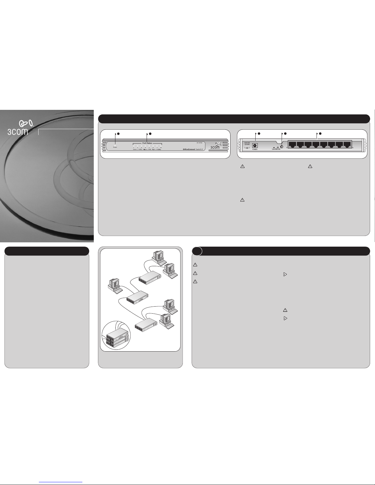
1 Power LED
green
Indicates that the Switch is powered on.
2 Five or Eight Port Status LEDs
green (100Mbps link) / yellow (10Mbps link)
If the LED is on, the link between the port and the
next piece of network equipment is OK. If the LED is
flashing, the link is OK and data is being transmitted
or received. If the LED is off, nothing is connected, or
the connected device is switched off, or there is a
problem with the connection (refer to the "Problem
Solving" section).
3 Power Adapter socket
Only use the power adapter that is supplied with
this Switch. Do not use any other adapter.
4 Uplink/Normal switch
Affects the operation of port 8. If you are
connecting another unit (such as a Hub or Switch)
to port 8, set to Uplink (in), otherwise set to Normal
(out). Refer to "Connecting Workstations and Other
Equipment to your Switch".
Note: For the Switch 5, substitute ‘port 5’ for
‘port 8’.
5 Five or Eight 10/100 ports
Use suitable TP cable with RJ-45 connectors. You
can connect your Switch to a workstation, or any
other piece of equipment that has a 10BASE-T or
100BASE-TX port. Each port is capable of
autosensing for 10Mbps or 100Mbps operation.
Ports operate in half-duplex mode as well as full
duplex mode.
OfficeConnect Switch - Front OfficeConnect Switch - Rear
Installation Guide
Page 2
Switchin
Switching
When a network of repeater hubs is in operation, any information
that is sent by the workstations is passed around the whole network
(regardless of the destination of the information). This can result in a
lot of unnecessary traffic that can slow the network down. The Switch
solves this problem because it ‘listens’ to the network and automatically learns what workstations can be reached through its ports. It
can then selectively pass on any information by transmitting the traffic
from the relevant port only (instead of all ports like a repeater hub).
This operation is called ‘switching’.
The Switch effectively divides up your network, localizing the network
traffic and passing on traffic as necessary. If you have workstations
that communicate frequently in the same part of the network, traffic
between them is not passed on unnecessarily to the remainder of the
network, thereby reducing the load. If you have any high
performance workstations that require a lot of bandwidth, connect
them directly to the Switch.
Connecting 10BASE-T and 100BASE-TX Networks
The 10/100 ports can each be connected to either a 10BASE-T or
100BASE-TX network. If you have both types of network, you can join
them together using the Switch allowing all your workstations to
communicate. Alternatively, if you use 10BASE-T and want to improve
network performance by introducing 100BASE-TX technology, the
Switch protects the investment in your existing workstations because
it maintains 10BASE-T connections to them.
4
HOW YOUR SWITCH CAN BE USED
The Switch has been designed to aid you when detecting and solving
possible problems with your network. These problems are rarely
serious; the cause is usually a disconnected or damaged cable, or
incorrect configuration. If this section does not solve your problem,
contact your supplier for information on what to do next.
Perform these actions first:
●
Ensure all network equipment is powered on.
●
Power each piece of network equipment off, wait about 5 seconds
and then power each one on.
CAUTION: Do not power the Switch off and on quickly. Wait
about five seconds between power cycles.
Check the following symptoms and solutions:
Power LED not lit. Check your power adapter connection. If there is
still no power, you may have a faulty power adapter which needs
replacing with another OfficeConnect power adapter. Do not use
any other power adapter with the Switch.
Port Status LED not lit for a port that has a TP cable connected.
After connection it may take several seconds for the port status LED's
to illuminate. The port status LED should turn Green or Yellow for
each port that is connected. Please refer to ‘About Your Switch’ for a
full description of the LEDs.
lf the Port Status LED has not lit after several seconds ensure the
connected device is powered, the TP cable is not damaged and that it
is correctly inserted at both ends.
Also check whether the correct cable is being used (i.e. straightthrough or crossover), if the uplink port is being used, and whether
the Uplink/Normal Switch is in the correct position.
Twisted Pair (TP) Cables
Cables can be shielded (screened) or unshielded; 3Com recommends that
you use shielded cable. Cables used for 100BASE-TX connections must be
data grade (Category 5). The maximum length you can use is 100m
(328ft).
Twisted Pair (TP) cables are very easy to use. To connect a TP cable, simply
slot the connector into the relevant RJ-45 port. When the connector is
fully in, its latch locks it into place. To disconnect the cable, push the
connector’s latch in and remove it.
When one end of a TP cable is connected to the Switch and the other
end to the network interface card of a workstation the units will
’autonegotiate’ to determine the fastest possible link speed between
them. This may take a few seconds and the outcome will be reflected in
the LEDs on the front of the Switch.
The Switch detects all port connections, so you can start using your
network immediately. If you need more ports, simply add another
OfficeConnect unit.
If the equipment connected to the Switch does not support
autonegotiation or if it has been disabled, it must be configured to
operate in half duplex mode
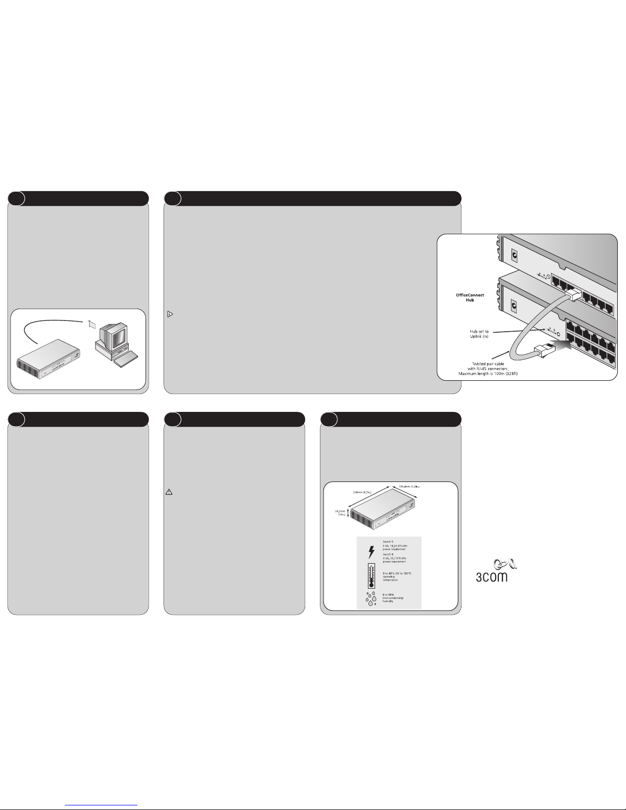
Expanding Your Network
You can increase the number of workstations that can connect to your
network by adding OfficeConnect Hubs and Switches. You can connect
either a 10BASE-T or a 100BASE-TX OfficeConnect unit to each port of
the Switch. Use the following method for each unit:
1. Connect the Uplink/Normal port of the unit to any of the
Switch’s ports (as shown in Figure 3). If using the highest
number port on the Switch (port 5 on Switch 5, port 8 on
Switch 8), set its Uplink/Normal switch to Normal (out).
2. Set the Uplink/Normal switch on the other unit to
Uplink (in).
If you are connecting your switch to a unit with automatic
MDI / MDIX functionality there is no need to follow the steps
described above. The connection will happen automatically.
Checking Unit Connections
When you have connected all your units, power on the units
and the Switch. The Port Status LEDs for the ports you have
used on both the units and the Switch should be on. If they
are not, check your connections and the settings of the
Uplink/Normal switches.
Spot Checks
At frequent intervals, visually check that:
●
Case vents are not obstructed.
●
Cabling is secure and not pulled taut.
3 CONNECTING WORKSTATIONS AND OTHER EQUIPMENT TO YOUR SWITCH
5 PROBLEM SOLVING
Dimensions and Operating Conditions
6 DIMENSIONS AND STANDARDS
Switch 5 480g (1.1 lb)
Switch 8 535g (1.3 lb)
OfficeConnect
Switch
Unit Connections
To connect OfficeConnect units (such as Hubs and other Switches) to
your Switch, you need:
●
One suitable Twisted Pair (TP) cable for each unit.
Workstation Connections
To connect workstations or other equipment (such as servers) directly
to your Switch, you need:
1. One 10BASE-T, 100BASE-TX or 10/100BASE-TX adapter card for
each workstation. 3Com produce a range of easy to install network
adapters.
2. An operating system (for example, NetWare or Windows
95/98/Me/2000) with network support configured, running on your
workstations.
3. One suitable Twisted Pair cable for each workstation.
2
BEFORE YOU INSTALL YOUR SWITCH
3
1
2
Figure 3 Correct Connections for an OfficeConnect Switch
Figure 2 Workstation connections
3Com Corporation, Corporate Headquarters, 5400 Bayfront Plaza, Santa Clara, CA 95052-8145
Copyright © 2001 3Com Corporation. All rights reserved. 3Com and OfficeConnect are registered trademarks
of 3Com Corporation. The 3Com logo is a trademark of 3Com Corporation.
Microsoft, MS-DOS, Windows and Windows NT are registered trademarks of Microsoft Corporation. Novell
and NetWare are registered trademarks of Novell, Inc.
All other company and product names may be trademarks of their respective companies
Standards
Functional: ISO 8802/3
IEEE 802.3, 802.3u
Safety: UL 1950, EN 60950
CSA 22.2 #950,
IEC60950
EMC: EN 55022 Class B
EN 55024
FCC Part 15 Class B*
ICES-003 Class B
VCCI Class B
CNS 13438 Class A
Environmental: EN 60068 (IEC 68)
* Refer to Regulatory Notices section in the Support and Safety Information sheet
 Loading...