

Page 1

Baseline Switch 2250 Plus
User Guide
Bedienungsanleitung
3C16476CS
http://www.3com.com/
Part No. 10015237 Rev. BA
Published February 2008
Page 2

3Com Corporation • 350 Campus Drive • Marlborough • MA USA 01752-3064
Copyright © 2006, 3Com Corporation. All rights reserved. No part of this
documentation may be reproduced in any form or by any means or used to
make any derivative work (such as translation, transformation, or
adaptation) without written permission from 3Com Corporation.
3Com Corporation reserves the right to revise this documentation and to
make changes in content from time to time without obligation on the part
of 3Com Corporation to provide notification of such revision or change.
3Com Corporation provides this documentation without warranty, term, or
condition of any kind, either implied or expressed, including, but not
limited to, the implied warranties, terms or conditions of merchantability,
satisfactory quality, and fitness for a particular purpose. 3Com may make
improvements or changes in the product(s) and/or the program(s) described
in this documentation at any time.
If there is any software on removable media described in this
documentation, it is furnished under a license agreement included with the
product as a separate document, in the hard copy documentation, or on
the removable media in a directory file named LICENSE.TXT or
!LICENSE.TXT. If you are unable to locate a copy, please contact 3Com and
a copy will be provided to you.
UNITED STATES GOVERNMENT LEGEND
If you are a United States government agency, then this documentation
and the software described herein are provided to you subject to the
following:
All technical data and computer software are commercial in nature and
developed solely at private expense. Software is delivered as “Commercial
Computer Software” as defined in DFARS 252.227-7014 (June 1995) or as
a “commercial item” as defined in FAR 2.101(a) and as such is provided
with only such rights as are provided in 3Com’s standard commercial
license for the Software. Technical data is provided with limited rights only
as provided in DFAR 252.227-7015 (Nov 1995) or FAR 52.227-14 (June
1987), whichever is applicable. You agree not to remove or deface any
portion of any legend provided on any licensed program or documentation
contained in, or delivered to you in conjunction with, this User Guide.
Unless otherwise indicated, 3Com registered trademarks are registered in
the United States and may or may not be registered in other countries.
3Com and the 3Com logo are registered trademarks of 3Com Corporation.
Microsoft, MS-DOS, Windows, and Windows NT are registered trademarks
of Microsoft Corporation.
IEEE and 802 are registered trademarks of the Institute of Electrical and
Electronics Engineers, Inc.
Netscape Navigator is a registered trademark of Netscape Communications.
JavaScript is a trademark of Sun Microsystems.
All other company and product names may be trademarks of the respective
companies with which they are associated.
ENVIRONMENTAL STATEMENT
It is the policy of 3Com Corporation to be environmentally-friendly in all
operations. To uphold our policy, we are committed to:
Establishing environmental performance standards that comply with
national legislation and regulations.
Conserving energy, materials and natural resources in all operations.
Reducing the waste generated by all operations. Ensuring that all waste
conforms to recognized environmental standards. Maximizing the
recyclable and reusable content of all products.
Ensuring that all products can be recycled, reused and disposed of safely.
Ensuring that all products are labelled according to recognized
environmental standards.
Improving our environmental record on a continual basis.
End of Life Statement
3Com processes allow for the recovery, reclamation and safe disposal of all
end-of-life electronic components.
Regulated Materials Statement
3Com products do not contain any hazardous or ozone-depleting material.
Environmental Statement about the Documentation
The documentation for this product is printed on paper that comes from
sustainable, managed forests; it is fully biodegradable and recyclable, and is
completely chlorine-free. The varnish is environmentally-friendly, and the
inks are vegetable-based with a low heavy-metal content.
Page 3

CONTENTS
ABOUT THIS GUIDE
Conventions 5
Related Documentation 6
Documentation Comments 6
1 INTRODUCING THE BASELINE SWITCH
Overview of the Baseline Switch 2250 Plus 7
Features and Capabilities 7
Autosensing of MDI/MDIX Connections 7
Autonegotiating 10/100 Mbps Ports 7
SFP Ports 8
Traffic Prioritization 8
Forwarding of BPDU Packets 8
Physical Features 9
Front Panel 9
Rear Panel 12
Package Contents 12
2 INSTALLING THE SWITCH
Before You Begin 13
Positioning the Switch 13
Aufstellen des Switch 14
Rack-Mounting or Free-Standing 14
Using the Mounting Kit 14
Montagesatz Anweisungen 15
Placing Units On Top of Each Other 16
Supplying Power to the Switch 16
Checking for Correct Operation 16
Connecting a Network Device 17
Using SFP Transceivers 18
Approved SFP Transceivers 18
Inserting an SFP Transceiver 18
Removing an SFP Transceiver 19
Performing Spot Checks 19
3 CONNECTING TO THE WEB INTERFACE
Requirements for Accessing the Web Interface 21
Running the Discovery Application 21
Logging On to the Web Interface 23
Navigating the Web Interface 23
Menu 23
Buttons 25
Accessing the Interface Without Using Discovery 26
DHCP Assigned IP Address 26
Manually Assigned (Static) IP Address 26
4 CONFIGURING THE SWITCH
Configuration Overview 27
Device Summary Information 27
Administration Settings 29
Modifying the IP Address Settings 29
Automatic IP Configuration 29
IP Setup 30
Page 4

Backup Configuration 30
Restore Configuration 30
Firmware Upgrade 31
Initialize 31
Reboot 32
System Access 32
System Time 34
SNMP 34
Configuring VLANs 36
VLAN 36
Forwarding Tagged/Untagged Frames 40
Sample VLAN Configurations 40
Spanning Tree 42
IGMP Snooping 43
IGMP Query 43
Broadcast Storm 44
Configuring Port Settings 44
Administration 44
Speed/Duplex for 1000 Mbps Connections 46
Link Aggregation 46
Spanning Tree per Port 48
Port Mirroring 50
Statistics 51
QoS VoIP Traffic Settings 52
Security 54
RADIUS Client 54
802.1X Settings 55
Monitoring 58
Address Table 58
Cable Diagnostics 58
Forgotten Password 61
Forgotten Static IP Address 62
Solving LED Issues 62
If the Problem Persists 63
A OBTAINING SUPPORT FOR YOUR PRODUCT
Register Your Product 65
Purchase Value-Added Services 65
Troubleshoot Online 65
Access Software Downloads 65
Telephone Technical Support and Repair 66
Contact Us 66
B SAFETY INFORMATION
Important Safety Information 69
C TECHNICAL INFORMATION
Related Standards 71
Environmental 71
Physical 71
Electrical 71
GLOSSARY
INDEX
REGULATORY NOTICES
5 TROUBLESHOOTING
Resetting to Factory Defaults 61
Page 5
ABOUT THIS GUIDE
This guide describes how to install your Switch and
perform initial management configurations.
This guide is intended for use by network administators who are responsible for installing and setting up
network equipment. Consequently, it assumes a basic
working knowledge of LANs (local area networks).
Diese Anleitung ist für die Benutzung durch
Netzwerkadministratoren vorgesehen, die für die
Installation und das einstellen von Netzwerkkomponenten verantwortlich sind; sie setzt Erfahrung bei der
Arbeit mit LANs (Local Area Networks) voraus.
If release notes are shipped with your product and
the information there differs from the information in
this guide, follow the instructions in the release notes.
Most user guides and release notes are available in
Adobe Acrobat Reader Portable Document Format
(PDF) on the 3Com World Wide Web site:
http://www.3com.com
Conventions
Ta bl e 1 and Tab le 2 list conventions that are used
throughout this guide.
Ta b l e 1 Notice Icons
Icon Notice Type Description
Information
note
Caution Information that alerts you to potential loss of
Warning Information that alerts you to potential
Ta b l e 2 Text Conventions
Convention Description
Screen displays
The words “enter”
and “type”
Words in italics Italics are used to:
Information that describes important features
or instructions
data or potential damage to an application,
system, or device
personal injury
This typeface represents information as it
appears on the screen.
When you see the word “enter” in this guide,
you must type something, and then press
Return or Enter. Do not press Return or Enter
when an instruction simply says “type.”
■ Emphasize a point.
■ Denote a new term at the place where it is
defined in the text.
■ Identify menu names, menu commands, and
software button names. Examples:
From the Help menu, select Contents.
Click OK.
Page 6
6 ABOUT THIS GUIDE
Related Documentation
In addition to this guide, each 3Com Baseline Switch
2250 Plus documentation set includes the following:
■ Online Help – Accessible from the Web interface,
provides information that helps you perform tasks
using the Web interface.
■ Release Notes – Provide information about the
current software release, including new features,
modifications, and known problems.
Documentation Comments
Your suggestions are very important to us. They will
help make our documentation more useful to you.
Please e-mail comments about this document to
3Com at:
Please include the following information when contacting us:
■ Document title
Please note that we can only respond to comments
and questions about 3Com product documentation
at this e-mail address. Questions related to technical
support or sales should be directed in the first
instance to your network supplier.
■ Document part number (on the title page)
■ Page number (if appropriate)
Example:
■ 3Com Baseline Switch 2250 Plus User Guide
■ Part number: 10015237
■ Page 25
Page 7

1
INTRODUCING THE BASELINE SWITCH
This chapter provides an overview of the features and
capabilities of the 3Com
It also identifies the contents of the Switch package
and helps you get to know the physical features of
the device.
®
Baseline Switch 2250 Plus.
Overview of the Baseline Switch 2250 Plus
The 3Com® Baseline Switch 2250 Plus is a versatile,
easy-to-use unmanaged switch. It is ideal for users
who want the high-speed performance of 10/100
switching with the added functionality of Gigabit
links but do not need sophisticated management
capabilities.
The Switch is shipped ready for use. No configuration
is necessary, unless you want to configure advanced
features such as VLAN support and link aggregation.
Features and Capabilities
The Switch has 48 shielded RJ-45, 10/100 Mbps
auto-negotiating ports and two 10/100/1000BASE-T
ports that operate in conjunction with two Small
Form Factor Pluggable (SFP) transceiver slots on the
front panel. Use these SFP transceiver slots for easy,
flexible connection to fiber-based Gigabit media.
While there are four physical Gigabit ports, only a
maximum of two can be operational at any given
time.
Autosensing of MDI/MDIX Connections
All ports on the Switch can autosense both medium
dependent interface (MDI) and medium dependent
interface crossover (MDIX) connections. This allows
you to connect network devices to each port using
either a normal straight-through TP (twisted pair)
cable or a ‘crossover’ TP cable.
Any port can therefore be used to connect to another
switch port, server, or workstation without additional
configuration.
Autonegotiating 10/100 Mbps Ports
Each 10/100 Mbps port automatically determines the
speed and duplex mode of the connected equipment
and provides a suitable switched connection. The
1000BASE-T ports also support automatic
10/100/1000 Mbps speed detection.
The 10/100 Mbps connections on these 1000BASE-T
ports can operate in either half-duplex or full-duplex
mode. 1000 Mbps connections, on the other hand,
only operate in full duplex mode.
Page 8

8 CHAPTER 1: INTRODUCING THE BASELINE SWITCH
SFP Ports
The two SFP ports support fiber Gigabit Ethernet
short-wave (SX) and long-wave (LX) SFP transceivers
in any combination. This offers you the flexibility of
using SFP transceivers to provide connectivity
between the Switch and a 1000 Mbps core network.
When an SFP port is in operation, the corresponding
10/100/1000BASE-T port is disabled.
Traffic Prioritization
The Switch offers priority queuing, which means all
packets that are received are examined to see if they
have been priority encoded. If a packet has been priority encoded, then the Switch will read the priority
level and determine whether the packet should be
directed through the normal or high priority channel.
This feature is useful during excessive loads when one
type of traffic may require priority over another. The
Switch is configured to comply with 802.1p, VLAN
tagged frames.
Traffic prioritization ensures that high priority data is
forwarded through the Switch without being delayed
by lower priority data. It differentiates traffic into
classes and prioritizes those classes automatically.
Traffic prioritization uses the multiple traffic queues
that are present in the hardware of the Switch to
ensure that high priority traffic is forwarded on a
different queue from lower priority traffic, and is
given preference over that traffic. This ensures that
time-sensitive traffic gets the highest level of service.
The 802.1D standard specifies eight distinct levels of
priority (0 to 7), each of which relates to a particular
type of traffic. The priority levels and their traffic types
are shown in the following table.
Ta b l e 3 Priority Levels for Traffic Types
Priority Level Traffic Type
0 Best effort
1 Background
2 Standard (spare)
3 Excellent effort (business critical)
4 Controlled load (streaming multimedia)
5 Video (interactive media), less than 100
milliseconds latency and jitter
6 Voice (interactive voice), less than 10
milliseconds latency and jitter.
7 Network control reserved traffic
Forwarding of BPDU Packets
Within an extended local area network that implements a spanning tree protocol topology, switches
communicate with each other using bridge protocol
data unit (BPDU) packets.
If your network is implementing a spanning tree
topology across multiples switches, you can configure
3Com Baseline Switch 2250 Plus to forward or to
block and discard bridge protocol data unit (BPDU)
packets to another switch. Switches that support the
spanning tree protocol communicate with each other
using BPDU packets.
The spanning tree protocol (STP) is a mechanism that
prevents looping and broadcast storms. A spanning
tree uses the spanning tree algorithm to detect
Page 9
Physical Features 9
available communication paths between switches and
to determine the best available path and block less
optimal paths.
For information on configuring BPDU forwarding and
blocking, refer to “
Physical Features
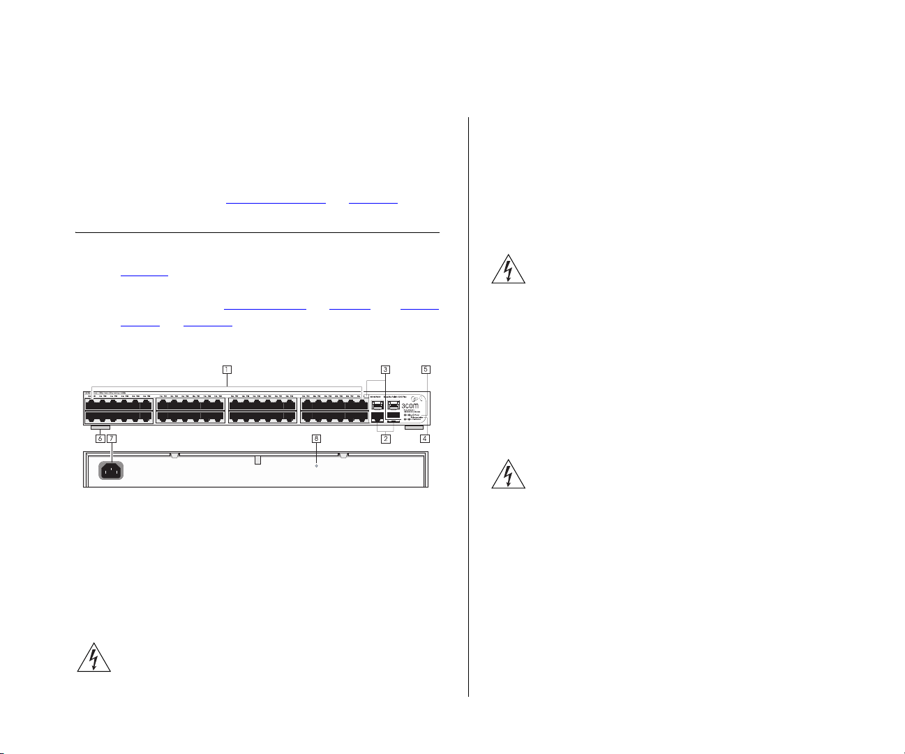
Figure 1 shows the front and rear panels of the
Switch. The numbers in this diagram refer to numbered sections in “
Panel” on page 12.
Figure 1 Front and Rear Panels
Front Panel
The front panel of the Switch contains a series of indicator lights (LEDs) that help describe the state of various networking and connection operations.
(1) 48 RJ-45 Ports
WARNING: RJ-45 Ports. These are shielded RJ-45
data sockets. They cannot be used as standard
traditional telephone sockets, or to connect the unit
Spanning Tree” on page 42.
Front Panel” on page 9 and “Rear
to a traditional PBX or public telephone network.
Only connect RJ-45 data connectors, network
telephony systems, or network telephones to these
sockets.
Either shielded or unshielded data cables with
shielded or unshielded jacks can be connected to
these data sockets.
AVERTISSEMENT: Points d’accès RJ-45. Ceux-ci sont
protégés par des prises de données. Ils ne peuvent
pas être utilisés comme prises de téléphone
conventionnelles standard, ni pour la connection de
l’unité à un réseau téléphonique central privé ou
public. Raccorder seulement connecteurs de données
RJ-45, systèmes de réseaux de téléphonie ou
téléphones de réseaux à ces prises.
Il est possible de raccorder des câbles protégés ou
non protégés avec des jacks protégés ou non
protégés à ces prises de données.
WARNHINWEIS: RJ-45-Porte. Diese Porte sind
geschützte Datensteckdosen. Sie dürfen weder wie
normale traditionelle Telefonsteckdosen noch für die
Verbindung der Einheit mit einem traditionellem
privatem oder öffentlichem Telefonnetzwerk
gebraucht werden. Nur RJ-45-Datenanscluße,
Telefonnetzsysteme or Netztelefone an diese
Steckdosen anschließen.
Entweder geschützte oder ungeschützte Buchsen
dürfen an diese Datensteckdosen angeschlossen
werden.
The Switch has 48 10/100 Mbps autonegotiating
ports (ports 1 to 48). Their speed and duplex mode
Page 10

10 CHAPTER 1: INTRODUCING THE BASELINE SWITCH
(half-duplex or full-duplex) are automatically
determined by the capabilities of the connected
device.
Each port also supports automatic MDI/MDI-X
detection and can be connected to either a 10BASE-T,
or a 100BASE-TX device.
CAUTION: The Switch supports full-duplex
autonegotiation. If the connected device does not
support autonegotiation, the Switch will operate in
half-duplex mode (even if the attached device is
operating in full-duplex mode).
In such a configuration, you may notice some
degradation of network performance. 3Com
recommends that you use devices that are capable of
autonegotiation (and that you ensure that
autonegotiation is enabled, if it is a configurable
option). (see “
Troubleshooting” on page 61).
(2) 10/100/1000BASE-T/SFP Ports
Ports 49 and 50 are combination Gigabit RJ-45 ports
with shared Small Form Factor Pluggable (SFP) transceiver slots. If an SFP transceiver (purchased separately) is installed in a slot and is active, the associated
RJ-45 port of the same number is disabled.
The two SFP ports support fiber Gigabit Ethernet
short-wave (SX) and long-wave (LX) SFP transceivers
in any combination. This offers you the flexibility of
using SFP transceivers to provide connectivity
between the Switch and remote 1000 Mbps
workgroups or to create a high-capacity aggregated
link backbone connection.
SFP ports are numbered 49 and 50 on the Switch.
When an SFP port is active, it has priority over the
10/100/1000 port of the same number. The
corresponding 10/100/1000 port is disabled when an
SFP transceiver is plugged in.
(3) Link/Activity LEDs
The following tables describe the LEDs visible on the
front of the Switch, and how to read their status
according to color.
Ta b l e 4 10BASE-T/100BASE-TX Ports
Status Meaning
Green Link established, operating at 100 Mbps
Yellow Link established, operating at 10 Mbps
Flashing Green Packets are being received or
transmitted on the port at 100 Mbps
The 1000BASE-T RJ-45 ports support automatic
MDI/MDI-X operation, so you can use
straight-through or crossover cables for all network
connections to workstations or servers, or to other
switches or hubs.
Page 11

Physical Features 11
Status Meaning
Flashing Yellow Packets are being received or
transmitted on the port at 10 Mbps
Off Link not established, either nothing is
connected to the port, or there is a
problem.
■ Verify that the attached device is
powered on
■ Verify that the cable or fiber is the
correct type and is not faulty
■ For fiber connections, ensure that the
receive (RX) and transmit (TX) cable
connectors are not swapped
If these checks do not identify the cause
of the problem, it may be that the unit
or the device connected to the port is
faulty. Contact your 3Com network
supplier for further advice.
Ta b l e 5 10BASE-T/100BASE-TX/1000BASE-T Ports
Status Meaning
Green Link established, operating at 1000
Mbps
Yellow Link established, operating at 10 or 100
Mbps
Flashing Green Packets are being received or
transmitted on the port at 1000 Mbps
Flashing Yellow Packets are being received or
transmitted on the port at 10 or 100
Mbps
Status Meaning
Flashing Yellow to
Port disabled or link loopback error
Green
Off Link not established, either nothing is
connected to the port, or there is a
problem.
■ Verify that the attached device is
powered on
■ Verify that the cable or fiber is the
correct type and is not faulty
■ For fiber connections, ensure that the
receive (RX) and transmit (TX) cable
connectors are not swapped
If these checks do not identify the cause
of the problem, it may be that the unit
or the device connected to the port is
faulty. Contact your 3Com network
supplier for further advice.
(4) Module Active LEDs
The Module Active LEDs show the status of any SFP
modules that are installed.
Ta b l e 6 Module Active LEDs
Status Meaning
Green Fiber SFP is inserted in the slot
Off No fiber SFP is inserted in the slot
Page 12

12 CHAPTER 1: INTRODUCING THE BASELINE SWITCH
(5) Power LED
The Power LED shows the power status of the Switch.
Ta b l e 7 Power LED
Status Meaning
Green The unit is powered on and ready for use
Flashing
Green
Yellow Power-on self-test or loopback test failed. If this
Off The unit is not receiving power:
Power-on self-test is in progress
occurs, reset the Switch to factory defaults. Refer
“Resetting to Factory Defaults”
to
■ Verify that the power cord is connected cor-
rectly
■ If the unit still does not operate, contact your
3Com network supplier
(6) Self-Adhesive Pads
The unit is supplied with four self-adhesive rubber
pads.
Do not apply the pads if you intend to rack-mount
the unit.
If the unit is to be part of a free-standing stack, apply
the pads to each marked corner area on the
underside of the unit. Place the unit on top of the
lower unit, ensuring that the pads locate within the
recesses of the lower unit.
Rear Panel
(7) Power Supply
The Switch automatically adjusts to the supply voltage. Only use the power cord that is supplied with
the unit.
(8) Recovery Button
Use the Recovery button on the rear panel to reset
the Switch to its factory defaults. For more information, refer to “
page 61
.
Package Contents
The 3Com Baseline Switch 2250 Plus package
includes the following items:
■ One 3Com Baseline Switch 2250 Plus unit
■ One power cord
■ Four standard height, self-adhesive rubber pads
■ One mounting kit
■ One CD-ROM, which contains this User Guide and
the 3Com Discovery application
■ One warranty flyer
Before installing and using the Switch, verify that your
Switch package has all these items. If any of the
above items are damaged or missing, contact your
3Com network supplier immediately.
Resetting to Factory Defaults” on
Page 13

2
INSTALLING THE SWITCH
This chapter contains information that you need to
install and set up the Switch. It covers the following
topics:
■ Positioning the Switch
■ Rack-Mounting or Free-Standing
■ Supplying Power to the Switch
■ Connecting a Network Device
■ Connecting a Network Device
■ Performing Spot Checks
Before You Begin
WARNING: Safety Information. Before installing or
removing any components from the Switch or carrying out any maintenance procedures, read the safety
information provided in Appendix B
AVERTISSEMENT: Consignes de sécurité. Avant
d'installer ou d'enlever tout composant du Switch ou
d'entamer une procédure de maintenance, lisez les
informations relatives à la sécurité qui se trouvent
dans Appendix B
WARNHINWEIS: Sicherheitsinformationen. Bevor
Sie Komponenten aus dem Switch entfernen oder
dem Switch hinzufuegen oder Instandhaltungsarbe-
of this guide.
(l'Appendice B) de ce guide.
iten verrichten, lesen Sie die Sicherheitsanweisungen,
die in Appendix B
(Anhang B) in diesem Handbuch
aufgefuehrt sind.
Positioning the Switch
The Switch is suitable for use in an office environment
where it can be free-standing or mounted in a standard 19-inch equipment rack.
Alternatively, the Switch can be rack-mounted in a
wiring closet or equipment room. A mounting kit,
containing two mounting brackets and four screws, is
supplied with the Switch.
When deciding where to position the Switch, ensure
that:
■ It is accessible and cables can be connected easily.
■ Cabling is away from sources of electrical noise.
These include lift shafts, microwave ovens, and air
conditioning units. Electromagnetic fields can
interfere with the signals on copper cabling and
introduce errors, therefore slowing down your
network.
■ Water or moisture cannot enter the case of the
unit.
■ Air flow around the unit and through the vents in
the side of the case is not restricted (3Com
Page 14
14 CHAPTER 2: INSTALLING THE SWITCH
recommends that you provide a minimum of 25
mm or 1 in. clearance).
■ The air is as free of dust as possible.
■ Temperature operating limits are not likely to be
exceeded. It is recommended that the unit is
installed in a clean, air conditioned environment.
It is always good practice to wear an anti-static wrist
strap when installing network equipment, connected
to a ground point. If one is not available, try to keep
in contact with a grounded rack and avoid touching
the unit's ports and connectors, if possible. Static discharge can cause reliability problems in your equipment.
Aufstellen des Switch
Bei der Entscheidung wo Sie den Switch positionieren, stellen Sie sicher das:
■ Der Switch zugänglich ist und die Kabel leicht
angeschlossen werden können.
■ Die Kabel nicht in der nähe von elektrischen
Störquellen befinden. Das schließt
Aufzugsschächte, Mikrowellen und Klimaanlagen
ein. Elektromagnetische Felder können die Signale
in den Kupferleitungen stören, und Fehler
verursachen, was die Verlangsamung Ihres
Netzwerkes zur Folge haben kann.
■ Weder Wasser noch Feuchtigkeit in das Gehäuse
eindringen kann.
■ Die Luftzirkulation um den Switch und durch die
Öffnungen des Gehäuses nicht behindert wird.
3Com empfiehlt das Sie 25mm (1 Inch)
Zwischenraum sicherstellen.
■ Die Luft so frei wie möglich von Staub ist.
■ Es unwahrscheinlich ist das die Betriebstemperatur
überschritten wird. 3Com empfiehlt das Sie den
Switch in einer sauberen, klimatisierten Umgebung
installieren.
Rack-Mounting or Free-Standing
The unit can be mounted in a 19-inch equipment rack
using the supplied mounting kit, (see “
Mounting Kit” on page 14), or it can be free-stand-
ing. Do not place objects on top of the unit or stack.
CAUTION: If installing the Switch in a free-standing
stack of different size Baseline or SuperStack
the smaller units must be installed above the larger
ones. Do not have a free-standing stack of more than
six units.
Using the Mounting Kit
The Switch is supplied with two mounting brackets
and four screws. These are used for rack mounting
the unit. When mounting the unit, take note of the
guidelines given in “
page 13
.
The Switch is 1U (1.75 in.) high and will fit in a standard 19-inch rack.
CAUTION: Before continuing, disconnect all cables
from the unit. Remove the self-adhesive pads from
the underside of the unit, if already fitted.
Positioning the Switch” on
Using the
®
3 units,
Page 15

Rack-Mounting or Free-Standing 15
To rack-mount the Switch:
1 Place the unit the right way up on a hard, flat surface
with the front facing towards you.
2 Locate a mounting bracket over the mounting holes
on one side of the unit.
3 Insert the two screws supplied in the mounting kit
and fully tighten with a suitable screwdriver.
Figure 2 Inserting the Screws
Montagesatz Anweisungen
Der Switch wird mit zwei Halterungen und vier
Schrauben geliefert. Diese werden für den Einbau in
einem Baugruppenträger benutzt. Bei der Montage
der Baugruppe beachten Sie die Anweisungen aus
“Aufstellen des Switch“.
Der Switch ist eine Baueinheit hoch und passt in einen
Standard 19'' (Zoll) Baugruppenträger.
ACHTUNG: Entfernen Sie alle Kabel, bevor Sie fortfahren. Entfernen Sie die selbstklebenden Polster
(Füße) von der Unterseite der Baugruppe, falls diese
bereits angebracht sind.
1 Platzieren Sie die Baugruppe aufrecht auf einer
harten, ebenen Fläche mit der Vorderseite zu Ihnen.
2 Ordnen Sie eine der Halterungen über den Löchern
an der Seite der Baugruppe an.
3 Stecken Sie zwei der mitgelieferten Schrauben in die
Löcher und drehen Sie diese mit einem geeigneten
Schraubendreher fest.
4 Wiederholen Sie die letzten zwei Schritte auf der
anderen Seite der Baugruppe.
4 Repeat the two previous steps for the other side of
the unit.
5 Insert the unit into the 19-inch rack and secure with
suitable screws (not provided). Ensure that the ventilation holes are not obstructed.
6 Reconnect the network cables.
5 Führen Sie die Baugruppe in den 19" (Zoll) Baugrup-
penträger ein und sichern sie die Baugruppe mit
geeigneten Schrauben. (Nicht im Lieferumfang
enthalten.)
6 Schließen Sie alle Kabel wieder an.
Page 16

16 CHAPTER 2: INSTALLING THE SWITCH
Placing Units On Top of Each Other
If the Switch units are free-standing, up to four units
can be placed one on top of the other. If you are
mixing a variety of Baseline and SuperStack units, the
smaller units must be positioned at the top.
If you are placing Switch units one on top of the
other, you must use the self-adhesive rubber pads
supplied. Apply the pads to the underside of each
Switch, sticking one in the marked area at each corner. Place the Switch units on top of each other,
ensuring that the pads of the upper unit line up with
the recesses of the lower unit.
Supplying Power to the Switch
Power problems can be the cause of serious failures
and downtime in your network. Ensure that the
power input to your system is clean and free from
sags and surges to avoid unforeseen network outages. 3Com recommends that you install power conditioning, especially in areas prone to black outs,
power dips and electrical storms.
The unit is intended to be grounded. Ensure it is connected to earth ground during normal use. Installing
proper grounding helps to avoid damage from lightning and power surges.
Before powering on the Switch, verify that network
cables and the power cable are securely connected.
power is by connecting or disconnecting the power
cord.
To power on the Switch:
1 Plug the power cord into the power socket on the
rear panel of the Switch. Refer to “
on page 12
2 Plug the other end of the power cord into a power
for more information.
(7) Power Supply”
outlet.
When the Switch is powered on, the Power LED lights
up. If the Power LED does not light up, refer to “
Power LED” on page 12 for more information.
Checking for Correct Operation
After you power on the Switch, it automatically performs a power-on self-test (POST). During POST, the
Power LED on the front panel of the Switch flashes
green.
When POST is complete, the Power LED turns green.
If the Power LED turns yellow after POST, it means
that POST failed.
Ta bl e 8
summarizes the possible colors for the Power
LED after POST.
Ta b l e 8 Possible Power LED Colors After POST
Color State
Green The unit is powered on and ready for use
(5)
CAUTION: The Switch has no ON/OFF switch; the
only method of connecting or disconnecting main
Page 17

Connecting a Network Device 17
Color State
Yellow Power-on self-test or loopback test failed.
This can happen if a port or ports fail when
the Switch was powered on.
Off The unit is not receiving power:
■ Verify that the power cord is connected
correctly, and then try powering on the
Switch again
■ If the Switch still does not operate, con-
tact your 3Com network supplier
If POST fails, try the following:
■ Power off the Switch, and then power it on again.
Check the Power LED and see if POST was
successfully completed.
■ Reset the Switch. See “Resetting to Factory
Defaults” on page 61.
CAUTION: Resetting the Switch to its factory defaults
erases all your settings. You will need to reconfigure
the Switch after you reset it.
If these do not resolve the issue:
■ Check the 3Com Knowledgebase for a solution. To
visit the 3Com Knowledgebase Web site, start your
Web browser, and then enter
http://knowledgebase.3com.com
■ Contact your 3Com network supplier for
assistance.
Connecting a Network Device
To connect a network device to the Switch, use Category 5 unshielded or shielded (screened) 100 Ohm TP
cables (or Category 3 cables for 10 Mbps connections).
For optimal connections, ensure that the cable length
for each connection is not longer than 100 m (328 ft).
Figure 3 Connecting Devices to the Switch
Baseline 10/100 switch
Baseline 10/100 switch
Baseline Switch 2250Plus
1000 Mbps link
10 or 100Mbps link
To connect a device to the Switch:
1 Connect one end of the cable to an RJ-45 port on the
Switch.
2 Connect the other end to the appropriate RJ-45 port
on the connecting device.
Endstations on switched
100 Mbps connections
Endstations on switched
100 Mbps connections
Endstations
on switched
10 or 100Mbps
connection
1000 Mbps copper
or fiber connection
to backbone or
server/workstation
Server on switched
1000 Mbps
connection
For 1000BASE-T operation, 3Com recommends using
Category 5e or 6 cables.
Page 18
18 CHAPTER 2: INSTALLING THE SWITCH
Using SFP Transceivers
The following sections describe how to insert and
remove an SFP transceiver from an SFP slot.
SFP transceivers are hot-insertable and hot-swappable. You can remove them from and insert them into
any SFP port without having to power off the Switch.
Approved SFP Transceivers
The following list of approved SFP transceivers is correct at the time of publication:
■ 3CSFP91 SFP (SX)
■ 3CSFP92 SFP (LX)
To access the latest list of approved SFP transceivers
for the Switch on the 3Com Corporation World Wide
Web site, enter this URL into your Internet browser:
http://www.3com.com
3Com recommends using 3Com SFPs in the Switch. If
you insert an SFP transceiver that is not supported,
the Switch will not recognize it.
fiber-optic cable or to multimode fiber using a
conditioned launch cable.
If the SFP transceiver is faulty, it will not operate
within the Switch. See “
page 61
.
Troubleshooting” on
To insert an SFP transceiver:
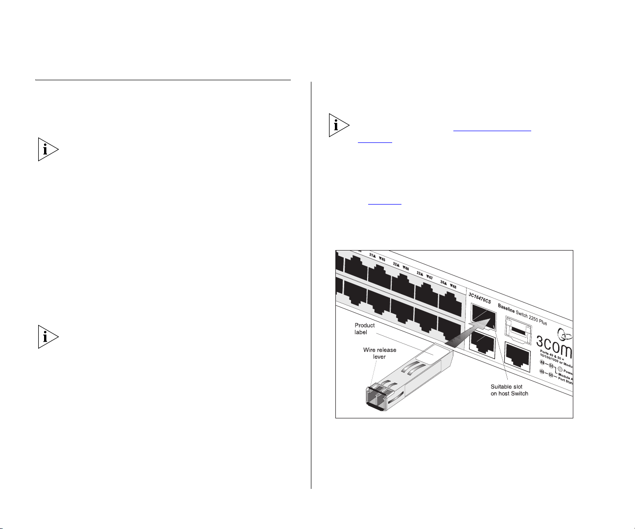
1 Hold the transceiver so that the fiber connector is
toward you and the product label is visible, as shown
in Figure 4
. Ensure the wire release lever is closed (in
the upright position).
Figure 4 Inserting the SFP Transceiver
Inserting an SFP Transceiver
To be recognized as valid, the SFP transceiver must be
one of the following:
■ 1000BASE-SX SFP transceiver – Use this transceiver
to connect the Switch directly to a multimedia
fiber-optic cable.
■ 1000BASE-LX SFP transceiver – Use this transceiver
to connect the Switch directly to a single-mode
2 Gently slide the transceiver into the SFP slot until it
clicks into place.
Page 19

Performing Spot Checks 19
CAUTION: SFP transceivers are keyed and can be
properly inserted only one way. If the transceiver does
not click when you insert it, remove it, turn it over,
and then re-insert it.
3 Remove the plastic protective cover, if fitted.
4 Connect the fiber cable.
5 The transceiver connects to the network using a
duplex LC connector. Attach a male duplex LC connector on the network cable into the duplex LC connector on the transceiver.
6 Connect the other end of the cable to a device fitted
with an appropriate Gigabit Ethernet connection.
7 Check the Module Active LEDs on the front of the
Switch to ensure that it is operating correctly.
Removing an SFP Transceiver
Removing an SFP transceiver does not require powering off the Switch.
To remove an SFP transceiver:
1 Disconnect the cable from the transceiver.
2 Move the wire release lever downwards until it is
pointing toward you.
Performing Spot Checks
At frequent intervals, you should visually check the
Switch. Regular checks can give you an early warning
of a possible failure; any problems can then be
attended to when there will be least effect on users.
3Com recommends periodically checking the items
listed in Ta b le 9
Ta b l e 9 Items to Check
Item Verify That
Cabling All external cabling connections are secure
Cooling fan Where possible, check that the cooling fan
If you experience any problems operating the Switch,
refer to “
.
and that no cables are pulled taut
is operating by listening to the unit. The
fan is fitted near to the front right hand
side of the unit (when viewed from the
front).
Troubleshooting” starting on page 61.
3 Pull the wire release lever toward you to release the
catch mechanism.
The SFP transceiver should slide out easily.
Page 20

20 CHAPTER 2: INSTALLING THE SWITCH
Page 21

3
CONNECTING TO THE WEB INTERFACE
The Switch has a built-in Web interface that you can
use to set the admin password, change the IP address
that is assigned to the Switch, and configure its
advanced settings.
If you only want the Switch to function as a basic
layer 2 switch, you do not need to access the Web
interface and configure the Switch.
This chapter provides information on how to gain
access to the Web interface using the Discovery
application. It also introduces the menu items and
buttons that are available on the Web interface.
The following topics are covered:
■ Requirements for Accessing the Web Interface
■ Running the Discovery Application
■ Logging On to the Web Interface
■ Navigating the Web Interface
Requirements for Accessing the Web Interface
To connect to the Web interface, you need the
following:
■ The Discovery application, which is included on the
3Com Baseline Switch 2250 Plus CD-ROM that is
supplied with your Switch
■ A computer that is connected to the Switch and
that has a Web browser
Running the Discovery Application
The 3Com Baseline Switch 2250 Plus CD-ROM
contains, among others, the Discovery application.
The Discovery application can be used for detecting
and connecting to the Switch on the network. The
application will launch a Web interface that provides
the user with options to configure, modify, and
upgrade the Switch.
To use Discovery to connect to the Web interface, do
the following:
1 On a computer that is connected to the Switch, insert
the CD-ROM into its CD drive.
Discovery should start automatically. If it does not
start automatically, go to the
the CD-ROM, and then double-click
\Discovery folder on
discovery.exe.
Page 22

22 CHAPTER 3: CONNECTING TO THE WEB INTERFACE
The Welcome screen of Discovery appears.
Figure 5 Welcome Screen of Discovery
2 If the computer has multiple network adapters, select
the adapter that connects the computer to the
Switch, and then click Next.
If the computer has only one adapter, click Next.
Figure 6 Discovered Devices Screen
3 On the Discovered Devices screen, click Baseline
Switch 2250 Plus, and then click Next.
The Completing the 3Com Discovery Application
screen appears.
4 Click Finish.
Discovery searches the network for 3Com devices.
When detection is complete, the Discovered Devices
screen displays detected network devices.
The logon dialog box for the Web interface appears.
Page 23

Logging On to the Web Interface 23
Logging On to the Web Interface
After the Web interface loads in your Web browser,
the first page that appears is the logon screen. On
this screen, you need to enter the administration user
name and password to gain access to the Web
interface.
The browser’s address bar also displays the IP address
that the Switch is currently using.
Figure 7 Logon Dialog Box
To log on to the Web interface:
Navigating the Web Interface
The Web interface has been designed to enable you
to easily perform advanced configuration tasks and
view information about the Switch.
Menu
The menu is located on the left side of the Web
interface. When you click an item on the menu, the
related screen appears in the main part of the
interface. Some menu items will give you sub-menu
tabs to choose from.
Figure 8 Switch Screen Layout
Sub-Menu Tabs
1 In User name, type admin.
2 Leave the Password field blank.
3 Click OK.
If your switch administration browser session remains
inactive for more than 10 minutes, the switch will
automatically log you out.
Menu
System Information
Page 24

24 CHAPTER 3: CONNECTING TO THE WEB INTERFACE
Ta bl e 1 0 lists the available items on the menu.
Table 10 Available Menu Items
Menu Item Description
Device Summary Contains tabs that allow you to:
■ Provide a summary of the Switch’s basic
settings and versions of current
components.
■ Set the polling interval in seconds.
■ Display the description for each color
coded port.
Save Configuration Saves the Switch’s configuration.
Administration Manages the device.
IP Setup Allows you to setup, modify, or view the IP
configuration parameters.
Backup Configuration Allows you to backup the Switch’s
configuration.
Restore Configuration Allows you to restore a saved configuration.
Firmware Upgrade Allows you to upgrade the current firmware
via HTTP.
Initialize Allows you to reset the Switch to factory
default settings.
Reboot Allows you to perform system reboot.
System Access Contains tabs that allow you to:
■ Display user summary information.
■ Create a new user.
■ Modify existing users.
■ Remove existing users.
System Time Allows you to set the system time.
Menu Item Description
SNMP Contains tabs that allow you to:
■ Set SNMP agent status.
■ Add community strings.
■ Remove community strings.
Device Configures the device.
VLAN Contains tabs that allow you to:
■ Create a VLAN.
■ Modify a VLAN.
■ Modify VLAN membership for a port.
■ Rename a VLAN.
■ Remove a VLAN.
■ Display VLAN membership for a port.
■ Display VLAN information.
Spanning Tree Allows you to configure a Spanning Tree
Protocol.
IGMP Snooping Allows you to enable or disable IGMP
snooping.
IGMP Query Allows you to enable or disable IGMP query
mode.
Broadcast Storm Allows you to enable and configure, or
disable rate limiting.
Port Configures the ports.
Administration Contains tabs that allow you to:
■ Display selected port information for the
entire Switch.
■ Display individual port information.
■ Modify the port settings.
Page 25

Navigating the Web Interface 25
Menu Item Description
Link Aggregation Contains tabs that allow you to:
■ Display link aggregation summary.
■ Create an aggregation group.
■ Modify the port memberships.
■ Remove an aggregation group.
Spanning Tree per
Port
Contains tabs that allow you to:
■ Display selected spanning tree
information for every port.
■ Display individual port spanning tree
information.
■ Modify the spanning tree settings for a
port.
Port Mirroring Monitor traffic going in and out of ports.
Statistics Display statistics for a selected port.
QoS Configures QoS settings.
VoIP Traffic Setting Contains tabs that allow you to:
■ Display Voice VLAN summary.
■ Configure Voice VLAN global settings.
■ Configure Voice VLAN port settings.
■ Display port information for Voice VLAN
and Trunk details.
■ Display OUI summary.
■ Add or remove OUI.
Security Configures security settings.
Radius Client Contains tabs that allow you to:
■ Display Radius Client information.
■ Configure Radius Client settings and set
authentication parameters.
Menu Item Description
802.1X Settings Contains tabs that allow you to:
■ Display 802.1X information.
■ Display 802.1X detailed information per
port.
■ Configure 802.1X settings.
Monitoring Display Switch monitoring information.
Address Table Displays MAC address table information for
ports and VLANs.
Cable Diagnostics Contains tabs that allow you to:
■ Display selected cable diagnostics
information for all ports.
■ Display all cable diagnostics information
per port.
Help Direct link to help pages.
Buttons
Depending on the screen that is currently displayed,
the following buttons may appear:
■ Apply – Click to save and apply any changes that
you have made
■ Cancel – Click to discard any unsaved changes
Page 26

26 CHAPTER 3: CONNECTING TO THE WEB INTERFACE
Accessing the Interface Without Using Discovery
The Discovery application works by automatically
detecting the IP address that is assigned to the
Switch, and then using that address to connect to the
Web interface. If you know the Switch’s IP address,
you can access the Web interface without using
Discovery.
This section describes how to access the interface
directly, without using Discovery.
If you do not configure the Switch’s IP address
settings, it will perform auto IP configuration to
assign an IP address to itself. For more information,
refer to “Automatic IP Configuration” on page 29.
To determine the IP address that the Switch will assign
to itself during auto IP configuration, check the
sticker on the base of the Switch. This sticker contains
the MAC address and default IP address of the
Switch.
DHCP Assigned IP Address
If you set the IP address mode to DHCP, check the
DHCP server for the IP address that is assigned to the
Switch, and then use that IP address to access the
Web interface.
Manually Assigned (Static) IP Address
If you assigned a static IP address to the Switch, you
need to use that IP address to access the Web
interface the next time you want to configure the
Switch.
For example, if you assigned the Switch the IP address
192.168.0.123, start your Web browser, and then
type
http://192.168.0.123.
For example, if the DHCP server assigned the IP
address 192.168.0.123 to the Switch, start your Web
browser, and then type
http://192.168.0.123.
Page 27

4
CONFIGURING THE SWITCH
This chapter provides information on how to
configure the Switch’s advanced features. Topics
include:
■ Device Summary Information
■ Administration Settings
■ Configuring VLANs
■ Configuring Port Settings
■ QoS VoIP Traffic Settings
■ Security
■ Monitoring
Configuration Overview
The Switch is shipped ready for use. If you only want
the Switch to function as a basic layer 2 switch, you
do not need to access the Web interface and
configure the Switch.
You only need to access the Web interface if you
want to:
■ Set the administration password to the Web
interface
If your switch administration browser session remains
inactive for more than 10 minutes, the switch will
automatically log you out.
Device Summary Information
The Device Summary screen, which automatically
loads after you log on to the Web interface, provides
a snapshot of the Switch’s basic settings and versions
of current components.
Click Device Summary on the menu. A screen appears
with three tabs that include:
■ Device View
■ Polling Interval
■ Color Key
Device View
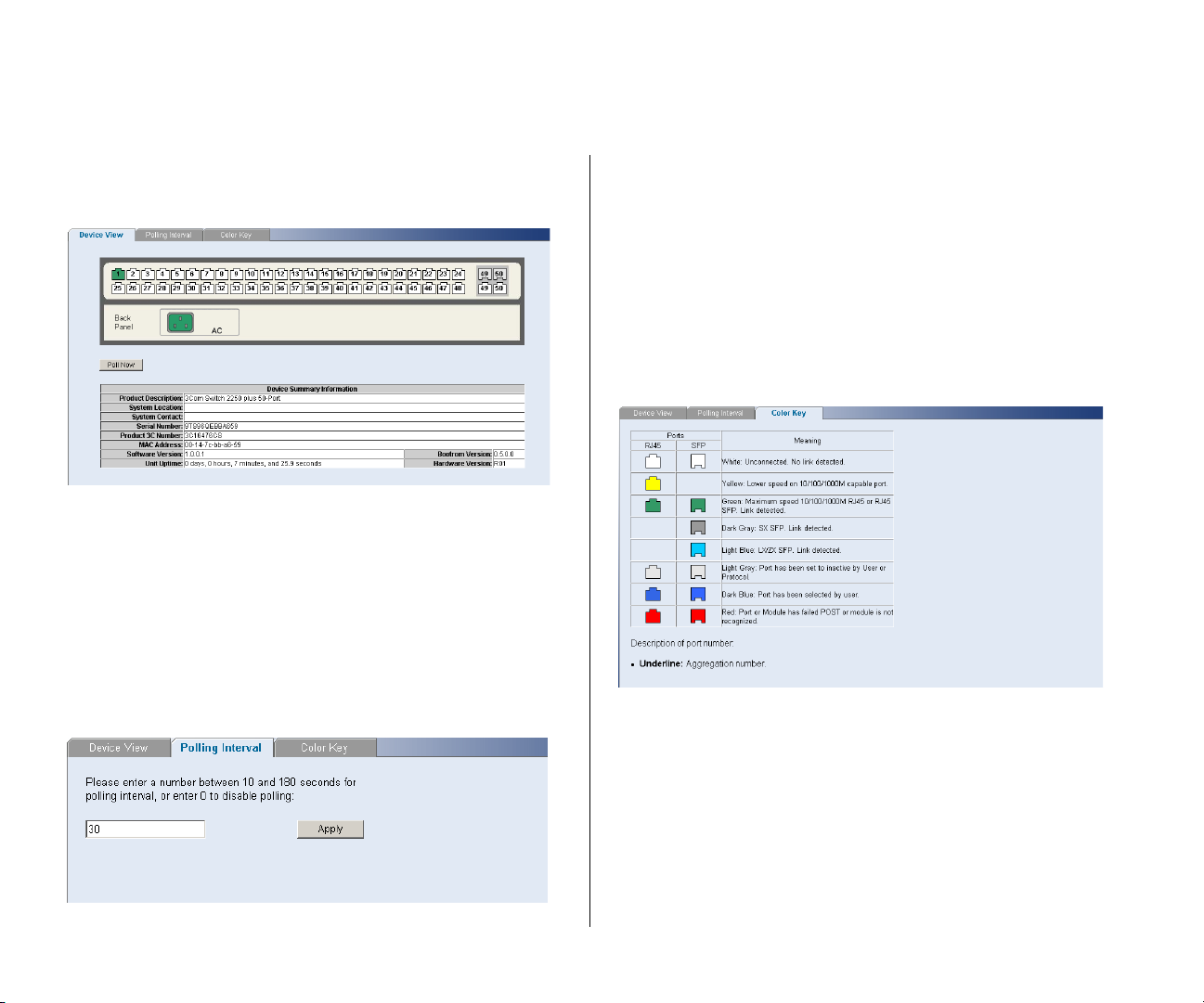
Contains fields that display the system, switch, and
management information to identify the Switch. The
fields include Product Description, System Location,
System Contact, Serial Number, Product 3C Number,
■ Assign an IP address to the Switch
■ Configure the Switch’s advanced features
■ Upgrade the firmware
Page 28
28 CHAPTER 4: CONFIGURING THE SWITCH
MAC Address, Software Version, Unit Uptime,
Bootroom Version, and Hardware Version.
Figure 9 Device View
If you request for technical assistance from 3Com
Support, you may be asked to print out the
information on this screen.
Polling Interval
Enter the interval in seconds you would like the
Switch to refresh. (Range: 10 to 180 seconds; 0 to
disable polling).
To set the polling interval:
1 Click the Device Summary menu, click Polling Interval
tab.
2 Enter a number between 10 to 180 seconds for the
polling interval. Enter a 0 to disable polling.
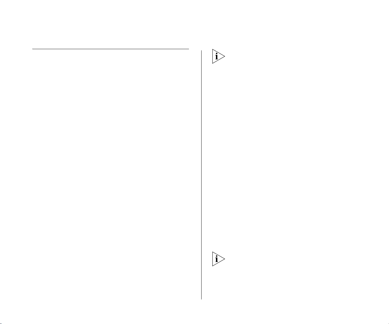
Color Key
Description of the color coding.
Figure 11 Color Key
Figure 10 Device View
Page 29
Administration Settings 29
Administration Settings
The Administration menu includes nine
administration items:
■ IP Setup
■ Backup Configuration
■ Restore Configuration
■ Firmware Upgrade
■ Initialize
■ Reboot
■ System Access
■ System Time
■ SNMP
Modifying the IP Address Settings
To enable devices on the network to communicate
with the Switch, you need to assign an IP address to it
— either by DHCP or by assigning a static IP address.
By default, the Switch performs automatic IP
configuration and assigns an IP address to itself. This
is necessary for the Discovery application to be able to
connect to the Web interface.
To determine the exact IP address that the Switch
assigns to itself during auto IP configuration, check
the sticker on the base of the Switch. This sticker
contains the MAC address and default IP address of
the Switch.
To detect its IP information using the automatic
configuration process, the Switch goes through the
following sequence of steps:
1 The Switch tries to configure itself with the default IP
address
169.254.x.y, where x and y are converted
from the last two bytes of its MAC address.
For example, if the MAC address is
IP address would be
169.254.1.2. This address is used
08004E000102, the
if the Switch is operating in a standalone mode, or no
other switches on the network have this IP address.
The Switch also assigns the subnet mask 255.255.0.0
(default class B mask) to itself.
2 If this default IP address is already in use on the
network, then the Switch detects this, and increments
the last byte of the MAC address by one to generate
its IP address.
The IP address would therefore become
3 The Switch repeats step 2 until an unused IP address
169.254.1.3.
is found.
Automatic IP Configuration
When you power on the Switch for the first time, it
automatically uses the default IP address
where
x and y are the last two bytes of its MAC
address.
169.254.x.y,
3Com recommends using automatic IP configuration
only for the initial setup. Once you gain access to the
Web interface, you should assign an IP address to the
Switch (either by using DHCP or assigning a static IP
address) to ensure successful communication
between the Switch and other network devices.
Page 30
30 CHAPTER 4: CONFIGURING THE SWITCH
IP Setup
To set the IP address for the Switch:
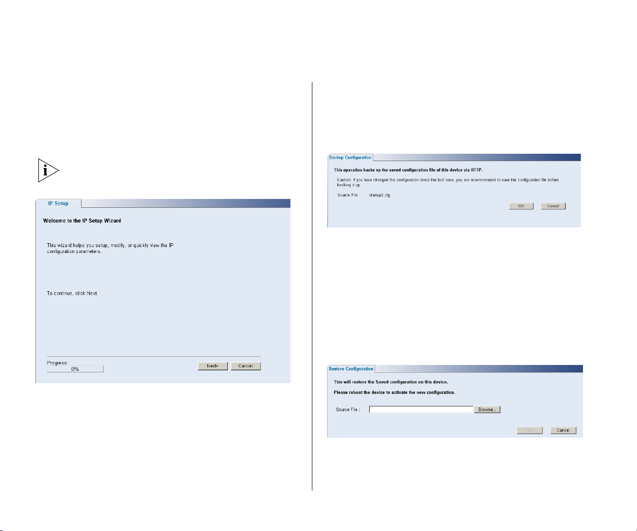
1 Click Administration, then IP Setting on the menu.
The IP Settings screen appears. Follow the IP Setup
Wizard to complete the setup.
This wizard can also be used to set system name,
location and contact information.
Figure 12 IP Settings Screen
Backup Configuration
To save the Switch configuration settings:
1 Click Administration, then Backup Configuration on
the menu. The Backup Configuration screen appears.
Figure 13 Backup Configuration
2 Click OK. You will be prompted to provide a location
where the configuration file will be saved.
Restore Configuration
To reload configuration settings that you previously
saved to a file:
1 Click Administration, then Restore Configuration on
the menu. The Restore Configuration screen appears.
Figure 14 Restore Configuration
2 Click Browse to locate the backup file on your
computer to restore the configuration settings.
Page 31
Administration Settings 31
3 Click Restore to copy the configuration back to the
Switch.
For security purposes, restoring the configuration
does not change the password.
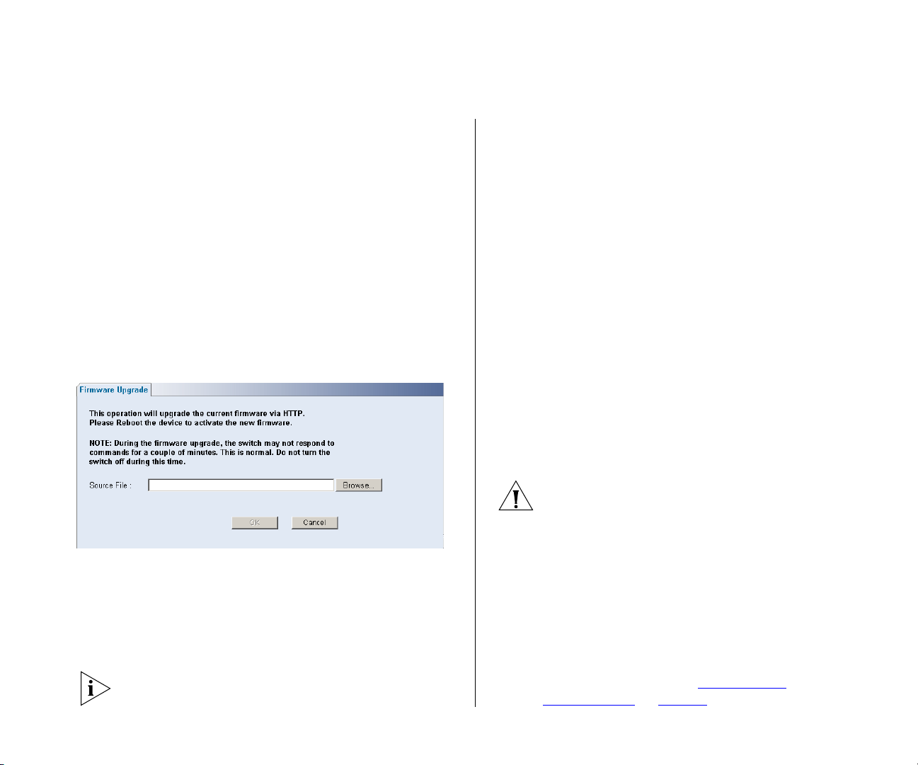
Firmware Upgrade
The Upgrade facility allows you to install on the
Switch any new releases of system firmware that
3Com may make available.
Newer versions of firmware can be downloaded via
HTTP and copied to the Switch; the Switch will restart
and apply the newer system firmware version.
Figure 15 Upgrade Screen
You may need to change the file type in the dialog
box displayed by your Web browser to *.* to be able
to see the file.
The file will be copied to the Switch, and once this
has completed, the Switch will restart. Although the
upgrade process has been designed to preserve your
configuration settings, 3Com recommends that you
make a backup of the configuration beforehand, in
case the upgrade process fails for any reason (for
example, the connection between the computer and
the Switch is lost while the new firmware is being
copied to the Switch).
A progress screen displays while the upgrade is taking
place.
The upgrade procedure can take a few minutes, and
is complete when the progress bar has finished
running and the Power LED has stopped flashing and
is permanently green.
CAUTION: Do not interrupt power to the Switch
during the upgrade procedure. If you do, the
firmware may be corrupted and the Switch may not
start up properly afterwards.
1 Click Administration, then Firmware Upgrade on the
menu. The Firmware Upgrade screen appears.
2 Once you have downloaded the firmware, use the
Browse button to locate the file on your computer,
and then click OK.
Initialize
To reset the Switch to factory default settings:
1 Click Administration, then Initialize on the menu.
You will lose all your configuration changes. The
Switch LAN IP address will revert to the default IP
address 169.254.x.y. (see “
Automatic IP
Configuration” on page 29). You may need to restart
Page 32
32 CHAPTER 4: CONFIGURING THE SWITCH
your computer to re-establish communication with
the Switch.
Reboot
Clicking on Administration, then Reboot on the menu
has the same effect as power cycling the unit. No
configuration information will be lost. Reboot the
Switch if you are experiencing problems and you
want to re-establish your Internet connection.
Any network users that are currently accessing the
Internet will have their access interrupted while the
reboot takes place, and they may need to restart their
computers when the reboot has completed and the
Switch is operational again.
System Access
Click Administration, then System Access on the
menu. A screen appears with four system access tabs:
■ User Summary
■ Create User
■ Modify User
To ensure that unauthorized users do not access the
Web interface, 3Com recommends that you set an
admin password when you first configure the Switch.
Even if you do not intend to actively manage the
switch, 3Com recommends that you change the
password to prevent unauthorized access to your
network.
The password can be up to 8 characters long and is
case-sensitive.
If you forget the administration password after you
set it, refer to “
Forgotten Password” on page 61 for
information on how to regain access to the Web
interface.
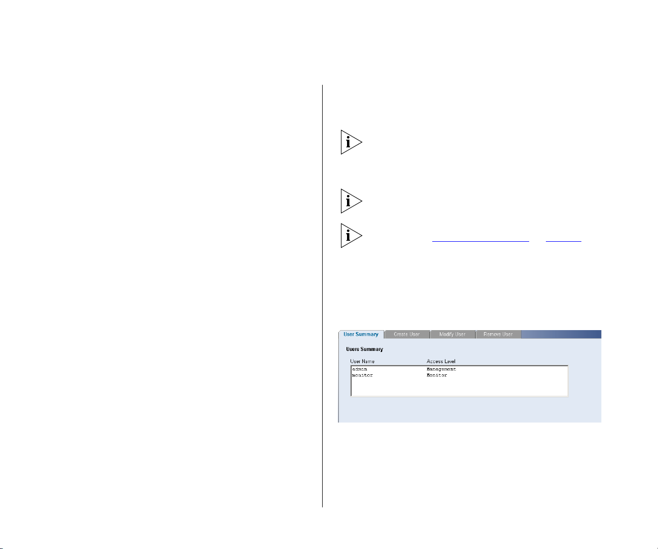
User Summary
Displays the list of user names and their access level.
Figure 16 User Summary Screen
■ Remove User
To prevent unauthorized users from accessing the
Web interface and modifying the Switch’s settings,
the interface is password-protected.
The default admin account settings are:
■ User name – admin
■ Password – blank (no password)
Page 33
Administration Settings 33
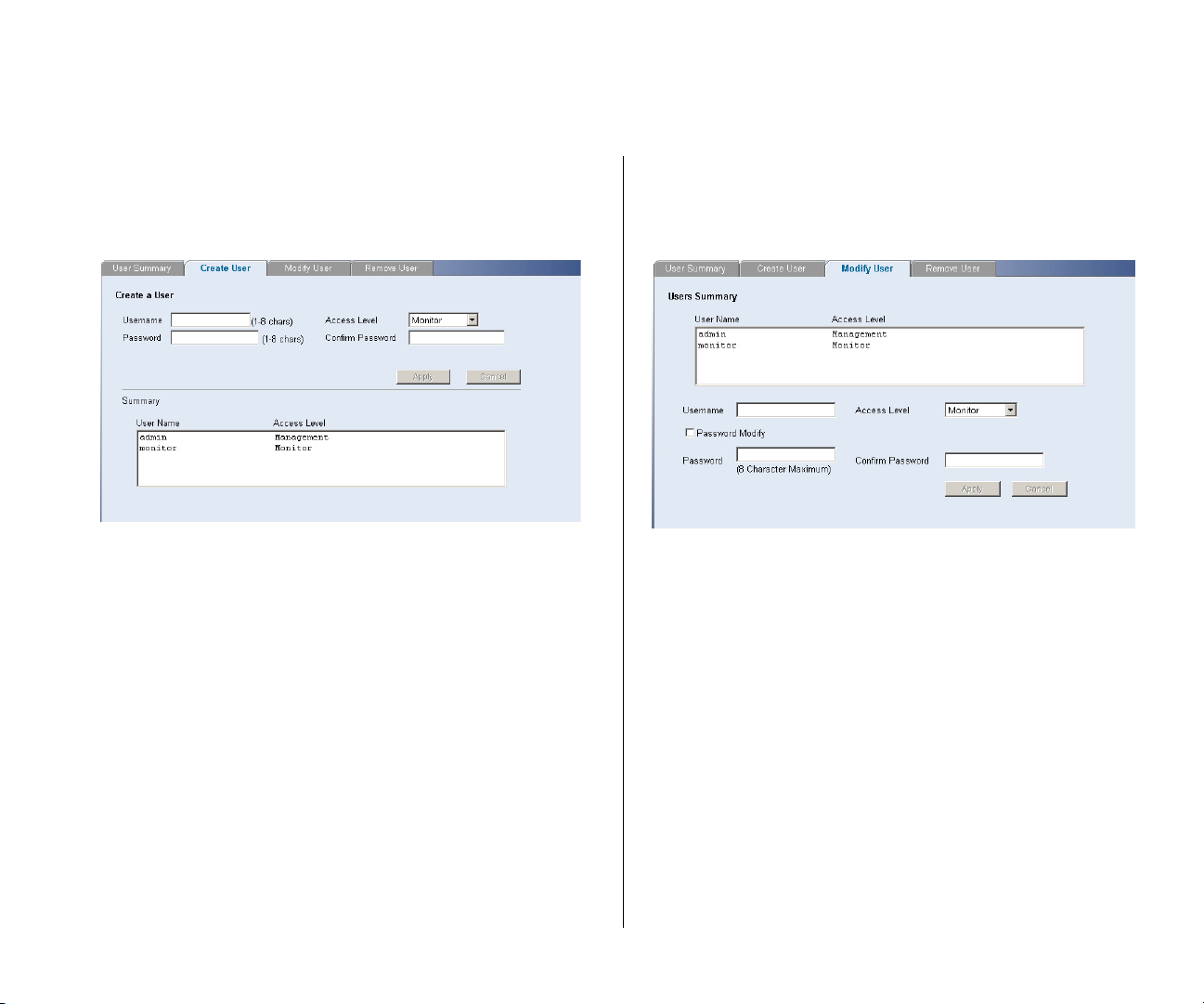
Create User
This page allows you to create a user and define the
access level and password for that user.
Figure 17 CreateUser Screen
Modify User
This page allows you to modify a user’s access level
and password.
Figure 18 Modify User Screen
Page 34
34 CHAPTER 4: CONFIGURING THE SWITCH
Remove User
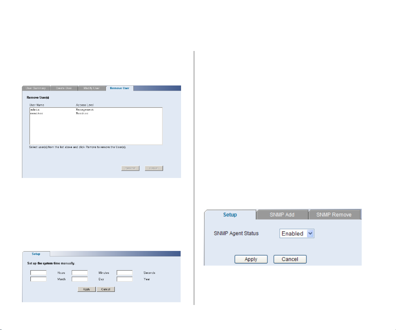
To remove a user from the Switch, click on the user
name, then click Remove.
Figure 19 Remove User Screen
System Time
Click Administration, then System Time on the menu.
This screen allows you to set the system time. You can
set the Year, Month, Day, Hours, Minutes, and
Seconds.
SNMP
Simple Network Management Protocol (SNMP) is a
communication protocol designed specifically for
managing devices on a network. Equipment
commonly managed with SNMP includes switches,
routers and host computers. SNMP is typically used to
configure these devices for proper operation in a
network environment, as well as to monitor them to
evaluate performance or detect potential problems.
Click Administration, then SNMP on the menu. A
screen appears with three tabs:
■ Setup
■ SNMP Add
■ SNMP Remove
Setup
Enable or disable the SNMP Agent Status.
Figure 21 SNMP Setup Screen
Figure 20 System Time Screen
Page 35
Administration Settings 35
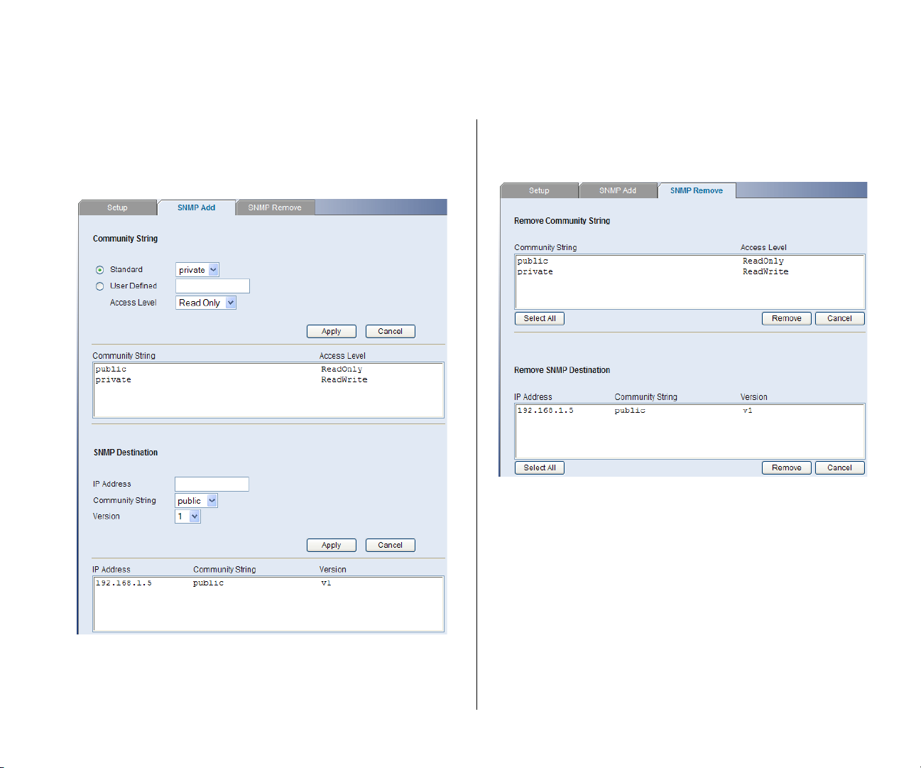
SNMP Add
This page allows you to create community strings for
management access.
Figure 22 SNMP Add Screen
SNMP Remove
This page allows you to remove community strings.
Figure 23 SNMP Remove Screen
Page 36
36 CHAPTER 4: CONFIGURING THE SWITCH
Configuring VLANs
A virtual LAN (VLAN) is a collection of network nodes
that share the same collision domain, regardless of
their physical location or connection point in the
network. A VLAN serves as a logical workgroup with
no physical barriers, and allows users to share
information and resources as though located on the
same LAN.
You can use the Switch to create VLANs to organize
any group of ports into separate broadcast domains.
VLANs confine broadcast traffic to the originating
group and help eliminate broadcast storms in large
networks. This also provides for a more secure and
cleaner network environment.
You can create up to 64 VLANs, add specific ports to
a chosen VLAN (so that the port can only
communicate with other ports on the VLAN), or
configure a port make it a member of multiple or
even all VLANs.
Communication between different VLANs can only
take place if they are all connected to a router or layer
3 switch.
VLAN
Click Device, then VLAN on the menu. A screen
appears with seven tabs that include:
■ Setup
■ Modify VLAN
■ Modify Port
■ Rename
■ Remove
■ Port Detail
■ VLAN Detail
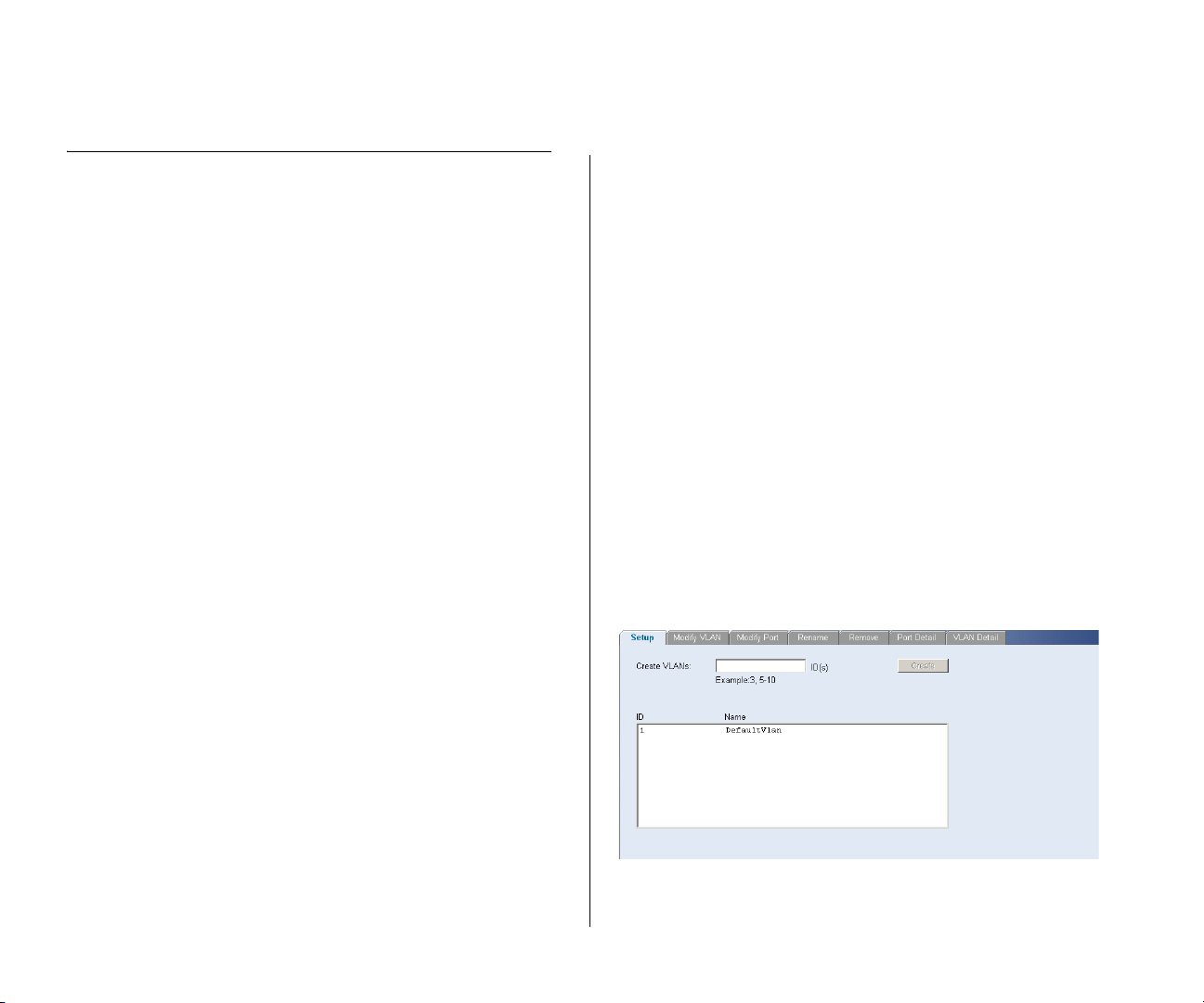
Setup
Use the Setup screen to create VLANs on the Switch.
To propagate information about VLAN groups used
on this Switch to external devices, you must specify a
VLAN ID for each VLAN.
Figure 24 Setup Screen
The Device menu includes five items:
■ VLAN
■ Spanning Tree
■ IGMP Snooping
■ IGMP Query
■ Broadcast Storm
Page 37
Configuring VLANs 37
Available options on the Setup screen include:
■ VLAN ID – ID of configured VLAN (1-4094, no
leading zeroes)
For examples on setting up VLANs, refer to “
Sample
VLAN Configurations”.
CAUTION: At least one port must always be an
untagged member of VLAN 1 (the management
VLAN). If you choose to connect all ports to VLANs
other than VLAN 1, you will no longer be able to
access the Web interface. If this happens, you will
need to reset the Switch to factory settings.
By default, all ports belong to VLAN 1 as untagged
members. However, they can belong to multiple
VLANs as tagged members. Also, newly created
VLANs will initially have no ports associated with
them.
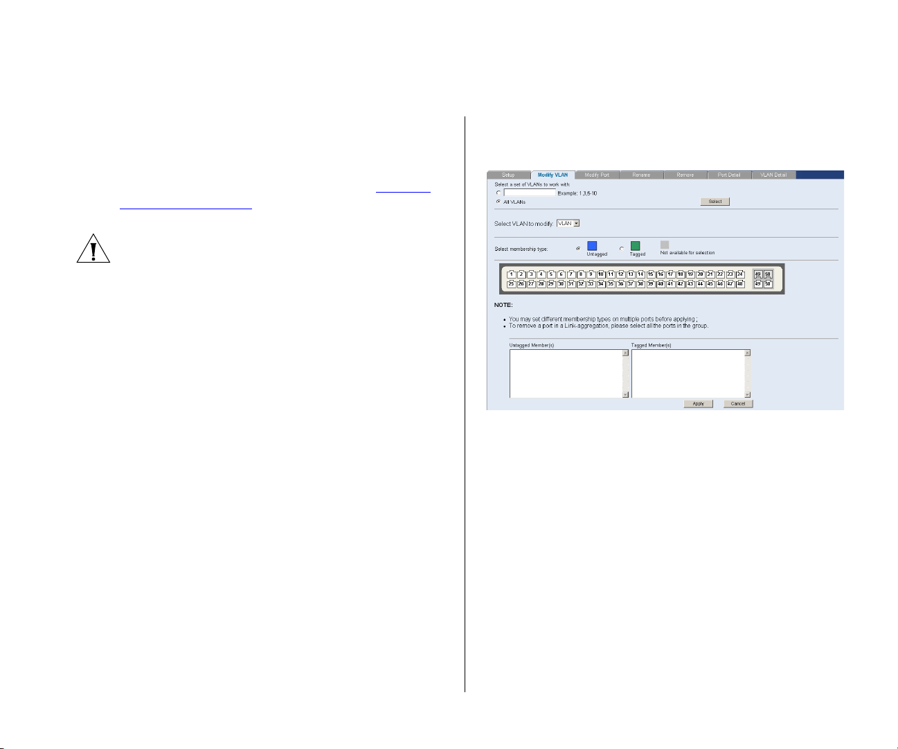
Modify VLAN
Use the Modify VLAN screen to change the VLAN to
which a port belongs, and configure the port to
communicate with all other VLANs, or a selected
VLAN.
Figure 25 Modify VLAN Screen
1 Enter a set of VLANs or select all VLANs to configure,
then click Select.
2 From the drop down menu, select a VLAN to modify.
3 Select a membership use. Available options for each
port include (only one option can be associated with a
single port):
■ Ta gg ed
■ Untagged
4 Select ports to associate with the membership, then
click Apply.
Page 38
38 CHAPTER 4: CONFIGURING THE SWITCH
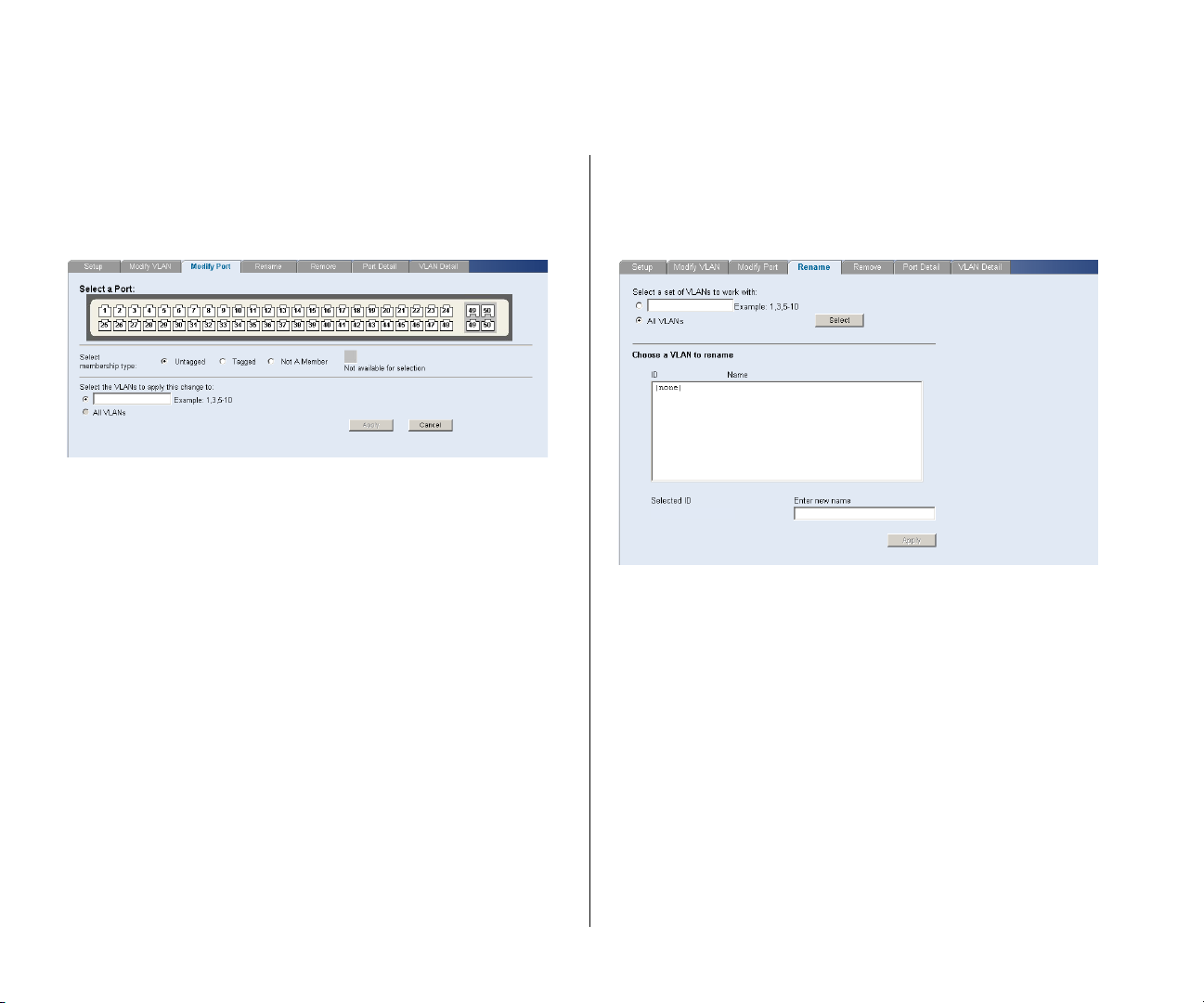
Modify Port
Use the Modify Port screen to modify the VLAN
membership of a port.
Figure 26 Modify Port Screen
1 Select a membership use. Available options for each
port include (only one option can be associated with a
single port):
■ Not a member
■ Tagged
■ Untagged
2 Select a port to associate with the membership.
3 Enter a VLAN to apply these changes to, then click
Apply.
Rename
Use the Rename screen to change the name of a
VLAN.
Figure 27 Rename Screen
1 Enter a set of VLANs or select all VLANs to add to the
rename list, then click Select.
2 From the list of selected VLANs, choose a VLAN to
rename. Enter a new VLAN name and click Apply.
Page 39
Configuring VLANs 39
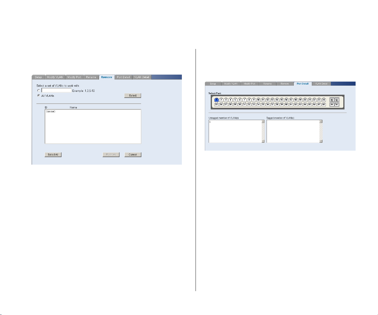
Remove
Use the Remove screen to remove a VLAN.
Figure 28 Remove Screen
1 Enter a set of VLANs or select all VLANs to add to the
remove list, then click Select.
2 From the list of selected VLANs choose a VLAN to
remove, or click the Select All button to select all the
VLANs. Click Remove to remove the VLAN.
Port Detail
Choose a port to display the tagged and untagged
VLAN memberships it is associated with.
Figure 29 Port Detail Screen
Page 40
40 CHAPTER 4: CONFIGURING THE SWITCH
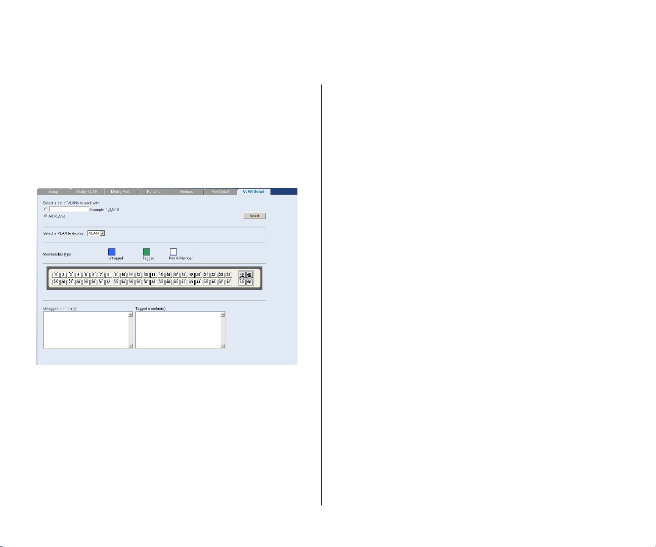
VLAN Detail
Use this screen to display detailed VLAN information.
1 Enter a set of VLANs or select all VLANs to add to the
details list, then click Select.
2 From the drop down menu, choose a VLAN to display
the associated tagged and untagged member ports.
Figure 30 VLAN Detail Screen
Forwarding Tagged/Untagged Frames
Each port on the Switch is capable of passing tagged
or untagged frames.
The following describes how the Switch will handle
tagged and untagged frames.
■ When a port receives a tagged frame with a VLAN
ID and the port is a member (untagged or tagged)
of that VLAN, the frame is accepted. Otherwise the
if the port is not a member of that VLAN, the
frame is discarded.
■ When a port receives an untagged frame and the
port is an untagged member of a VLAN, the frame
is accepted and assigned to that VLAN ID.
Otherwise if the port is not an untagged member
of any VLAN, the frame is discarded.
The Switch will only forward a frame to ports that are
members (tagged or untagged) of the VLAN to which
the frame is assigned. If the port is an untagged
member, the egress frame will be stripped of the
VLAN tag and forwarded as untagged. However, if
the port is a tagged member, the egress frame is
forwarded as tagged.
Sample VLAN Configurations
To illustrate how you can segment network devices
that are connected to the Switch, the following
sample configurations are provided.
Page 41
Configuring VLANs 41
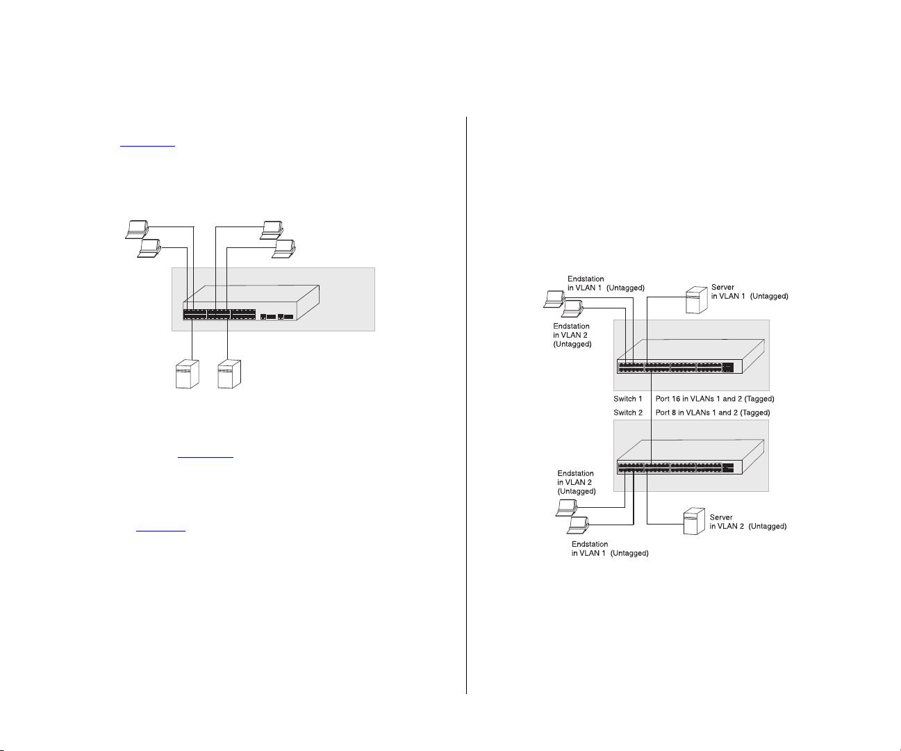
Setting Up Two VLANs on the Same Switch
Figure 31
illustrates how you can set up a simple
VLAN on the Switch using desktop connections.
Figure 31 Desktop VLAN Configuration
Server
in VLAN 1
Endstations
in VLAN 1
Endstations
in VLAN 2
Port 1
Port 3
Port 26
Server
in VLAN 2
Baseline Switch 2250Baseline Switch 2250 Plus
If you want to add ports 1, 3, and 26 to VLAN2 (as
shown in Figure 31
), so that the ports on the default
VLAN1 and the ports on VLAN2 cannot communicate
with each other, do the following:
1 Create a new VLAN and set the VLAN ID to 2. Refer
to “
Setup” for instructions. VLAN1 is the default
VLAN and already exists.
Setting Up VLAN Across Two Switches
This example explains how you can set up a VLAN
across two Switches using Tagged ports. This enables
ports that are members of the same VLAN (but are on
different switches) to communicate, provided that a
port on each Switch is set to Tagged, and that these
ports are connected.
Figure 32 Tagged VLAN Configuration
2 Set ports 1, 3, and 26 to associate with the Untagged
membership in VLAN2.
3 Click Apply.
Ports 1, 3, and 26 now belong to VLAN2, and will not
communicate with any other ports, unless you add
other ports to the VLAN or change the port
configuration.
Page 42

42 CHAPTER 4: CONFIGURING THE SWITCH
To set up the configuration shown in Figure 32, do
the following:
1 Create VLAN2 on both Switch 1 and Switch 2. You
need not create VLAN1 since it exists by default.
2 On Switch 1, set the ports that you want to be part of
VLAN2 to Untagged. Set one port (for example, port
16) to Tagged.
Click Apply.
3 On Switch 2, set the ports that you want to be part of
VLAN2 to Untagged. Set one port (for example, port
8) to Tag ged .
Click Apply.
4 Connect the Tagg ed port on Switch 1 (in this
example, port 16) to the Ta gg ed port on Switch 2 (in
this example, port 8).
Those ports on Switch 1 that are members of VLAN2
can now communicate with those ports on Switch 2
that are members of VLAN2.
Spanning Tree
Spanning tree uses a distributed algorithm to select a
bridging device that serves as the root of the
spanning tree network. The bridging device, known
as the Root Bridge, generates bridge protocol data
units (BPDUs) on all ports at a regular interval known
as the Hello Time. All other spanning tree-compliant
devices on the network have a designated Root Port.
This is the Port nearest the Root Bridge and it is used
for receiving the BPDUs initiated by the Root Bridge. If
a bridge does not get a Hello BPDU after a
predetermined interval, the bridge assumes that the
link to the Root Bridge is down. This bridge will then
initiate negotiations with other bridges to reconfigure
the network to reestablish a valid network topology.
After all the bridges on the network have determined
the configuration of their ports, each bridge only
forwards traffic between the Root Port and the ports
that are the Designated Bridge Ports for each network
segment. All other ports are blocked, which means
that they are prevented from forwarding traffic.
Spanning tree is a bridge-based system for providing
fault tolerance on networks and can be used to
detect and disable network loops. The spanning tree
ensures that the optimal path is maintained between
spanning tree-compliant networked devices by:
■ Disabling redundant paths when the main paths
are operational.
■ Enabling redundant paths if the main paths fail.
Page 43
Configuring VLANs 43
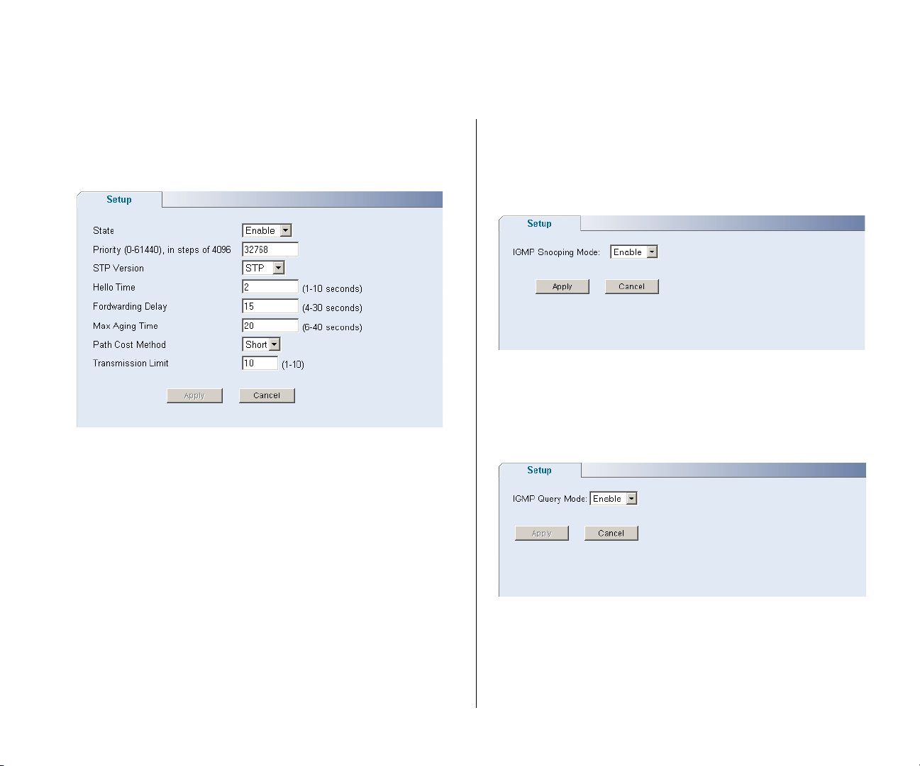
To use spanning tree, choose Enabled from the State
drop down menu, fill in the setup parameters, and
click Apply.
Figure 33 Spanning Tree Screen
IGMP Snooping
This switch uses IGMP (Internet Group Management
Protocol) to query for any attached hosts that want to
receive a specific multicast service. It identifies the
ports containing hosts requesting to join the service
and sends data out to those ports only. It then
propagates the service request up to any neighboring
multicast switch/router to ensure that it will continue
to receive the multicast service. This procedure is
called multicast filtering.
instead of flooding traffic to all ports in the subnet
(VLAN).
Choose Enabled or Disabled from the IGMP Snooping
Mode drop down menu.
Figure 34 IGMP Snooping Setup Screen
IGMP Query
Choose Enabled or Disabled from the IGMP Query
Mode drop down menu.
Figure 35 IGMP Query Setup Screen
The purpose of IP multicast filtering is to optimize a
switched network’s performance, so multicast packets
will only be forwarded to those ports containing
multicast group hosts or multicast routers/switches,
Page 44
44 CHAPTER 4: CONFIGURING THE SWITCH
Broadcast Storm
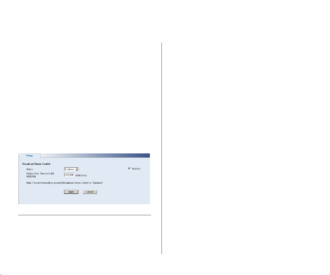
Use the Broadcast Storm page to set the Switch’s
broadcast storm control and threshold limits.
A broadcast storm occurs when an incorrect packet is
sent out on a network, causing most hosts to respond
all at once and typically with wrong answers that start
the process over again. Broadcast storms use
substantial network bandwidth and may cause
network time-outs.
The settings include:
■ Status – Enables and disables broadcast storm
control.
■ Packet Rate Threshold – Sets the broadcast storm
threshold (64 to 1000000 kilobits per second).
Figure 36 Broadcast Storm Setup Screen
current connection status of each port or shut down
or disable ports.
The Port menu includes five items:
■ Administration
■ Link Aggregation
■ Spanning Tree per Port
■ Port Mirroring
■ Statistics
Administration
Three tabs are available on the Port Administration
page:
■ Summary
■ Detail
■ Setup
Configuring Port Settings
Using the Web interface, you can configure the
speed/duplex, flow control, link aggregation, and port
mirroring settings of each port. You can also view the
Page 45
Configuring Port Settings 45
Summary
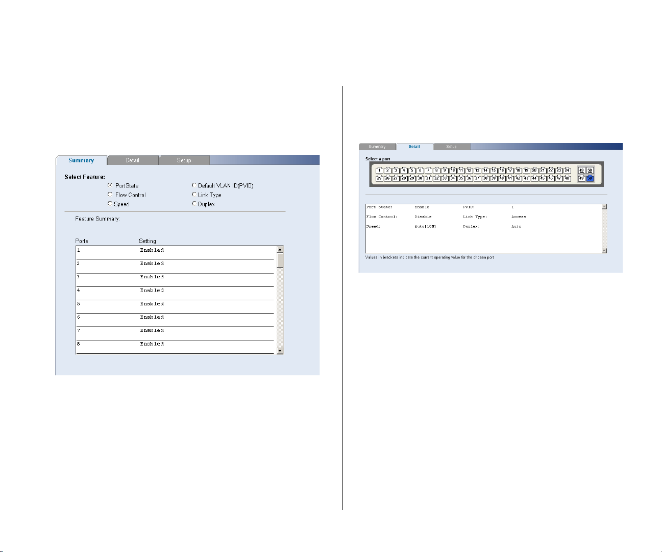
Use the Summary tab to display Port State, Flow
Control, Speed, Default VLAN ID, Link Type, or Duplex
for all the ports.
Figure 37 Port Administration Summary Screen
Detail
Use the Detail tab to display detailed port setting
information for a port.
Figure 38 Port Administration Detail Screen
Setup
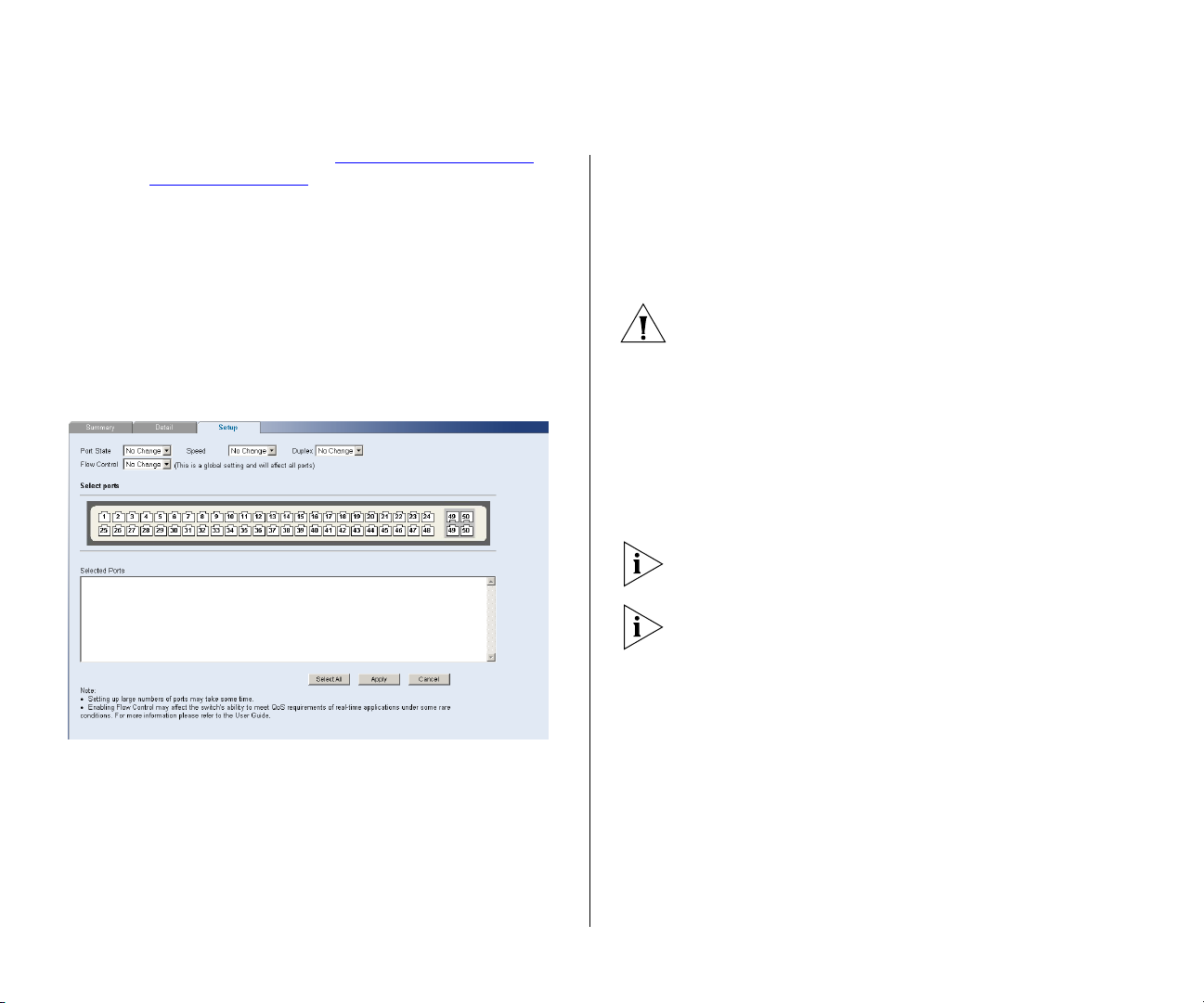
Use the Setup tab to configure the port settings. The
following options are available:
■ Port State – Enables and disables the port.
■ Flow Control – Enables and disables flow control
for the entire Switch. When flow control is
enabled, the Switch regulates the packet flow so
that a sending device does not transmit more
packets than a receiving device can process. If flow
control is disabled, packets may be dropped under
certain periods of high traffic.
Flow control is disabled by default.
■ Speed – Sets the speed mode of the port. Available
options include auto, 10, 100, and 1000. For 1000
Page 46
46 CHAPTER 4: CONFIGURING THE SWITCH
Mbps connections, see “Speed/Duplex for 1000
Mbps Connections” below.
Auto (or autonegotiation) sets the optimum
combination of speed and duplex that can be
supported by both ends of the link.
■ Duplex – Sets the duplex mode of the port.
Available options include auto, half, and full.
If you modify any of these settings, click Apply to save
your changes.
Figure 39 Port Administration Setup Screen
providing the connected device also supports this
speed.
1000 Mbps connections are always full-duplex.
Half-duplex connections are only available for 10
Mbps and 100 Mbps settings.
CAUTION: Before manually setting a port to
full-duplex, verify that the device connected to the
port is also manually set to the same speed and
duplex setting. If connecting link partners are left to
autonegotiate for a link manually set on this switch to
full-duplex, they will always negotiate to half-duplex,
resulting in a duplex mismatch. This can result in a
significant reduction in network performance. If you
are unsure of how to configure the speed/duplex
setting, simply enable autonegotiation for the port.
You cannot modify the speed/duplex settings of ports
that are members of a trunk or aggregated link.
Supported SFP transceivers only operate at
1000 Mbps full-duplex. Inserting an SFP transceiver
into a gigabit port disables the corresponding RJ-45
port, even if no fiber cable is inserted.
Speed/Duplex for 1000 Mbps Connections
You cannot preset the speed to 1000 Mbps. To r un a
port at 1000 Mbps, you must enable autonegotiation
for the port. When autonegotiation is enabled, the
Switch will automatically connect at 1000 Mbps,
Link Aggregation
Link aggregation, also called “trunking”, refers to
bonding multiple ports into a single group to
effectively combine the bandwidth into a single
connection or a “trunk”. If you are connecting the
Switch to another switch or to an Internet backbone,
you can aggregate links on the Switch to increase
throughput and prevent packet loopback between
switches.
Page 47
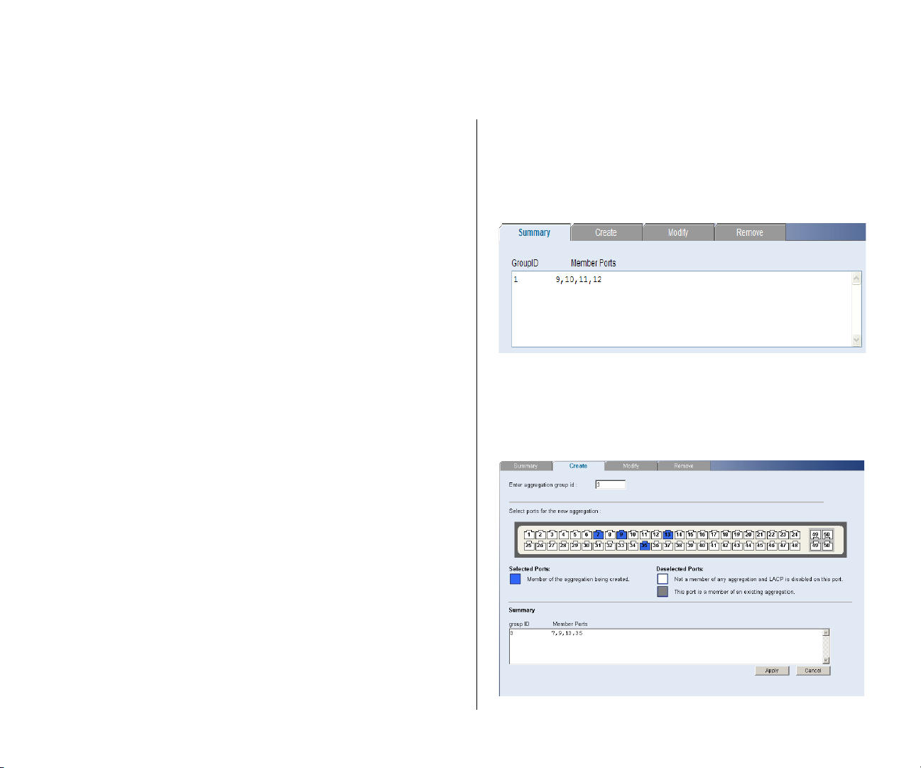
Configuring Port Settings 47
For link aggregation to work, the trunks must be
configured on both ends (switches).
Guidelines for Creating Trunks
■ Any port on the Switch can be used for creating a
trunk.
■ This switch supports a maximum of four trunks.
■ Each trunk may contain up to eight members.
■ A port may only be a member of one trunk at any
one time.
■ All ports in a trunk must be configured in an
identical manner, including communication mode
(that is, speed, duplex mode and flow control).
Four tabs are available on the Port Link Aggregation
page:
■ Summary
■ Create
■ Modify
■ Remove
Summary
Use the Summary tab to display a list of configured
link aggregation Group IDs and the associated
member Ports.
Figure 40 Link Aggregation Summary Screen
Create
Use the Create tab to add ports to a group
membership.
Figure 41 Link Aggregation Create Screen
Page 48
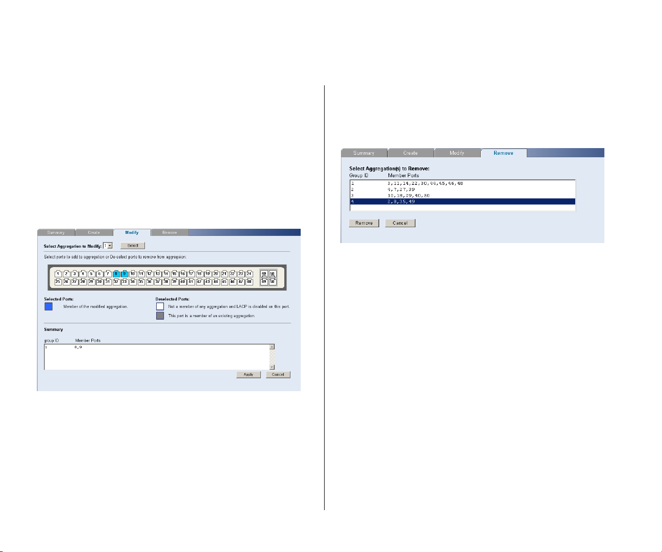
48 CHAPTER 4: CONFIGURING THE SWITCH
To create a new link aggregation group:
1 Enter a link aggregation group ID in the text box.
2 Select the ports to add to the goup.
3 Click Apply.
Modify
Use the Modify tab to reassign member ports of a link
aggregation group.
Figure 42 Link Aggregation Modify Screen
Remove
Use the Remove tab to delete a link aggregation
group.
Figure 43 Link Aggregation Remove Screen
To remove a link aggregation group:
1 From the link aggregation group list, select the
aggregated group to remove.
2 Click Remove.
Spanning Tree per Port
This administrative tool supports the configuration of
the Switch to forward, or block and discard 802.1D
spanning tree BPDU packets.
To modify a link aggregation group:
1 Select the aggregation group to modify, then click
Select.
2 Select the ports to add to, and/or remove from the
goup.
3 Click Apply.
Spanning tree is a bridge-based system for providing
fault tolerance on networks and can be used to
detect and disable network loops. The spanning tree
ensures that the optimal path is maintained between
spanning tree-compliant networked devices by:
Page 49
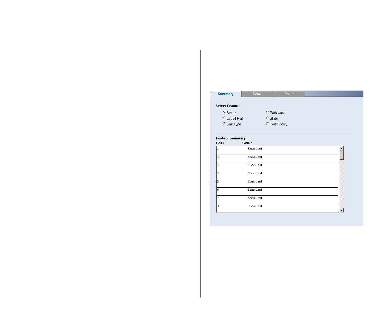
Configuring Port Settings 49
■ Disabling redundant paths when the main paths
are operational.
■ Enabling redundant paths if the main paths fail.
Spanning tree uses a distributed algorithm to select a
bridging device that serves as the root of the
spanning tree network. The bridging device, known
as the Root Bridge, generates BPDUs (Bridge Protocol
Data Units) on all ports at a regular interval known as
the Hello Time. All other spanning tree-compliant
devices on the network have a designated Root Port.
This is the Port nearest the Root Bridge and it is used
for receiving the BPDUs initiated by the Root Bridge. If
a bridge does not get a Hello BPDU after a
predetermined interval, the bridge assumes that the
link to the Root Bridge is down. This bridge will then
initiate negotiations with other bridges to reconfigure
the network to re-establish a valid network topology.
After all the bridges on the network have determined
the configuration of their ports, each bridge only
forwards traffic between the Root Port and the ports
that are the Designated Bridge Ports for each network
segment. All other ports are blocked, which means
that they are prevented from forwarding traffic.
Summary
Use the Summary tab to display Status, Edged Port,
Link Type, Path Cost, State, or Port Priority for all the
ports.
Figure 44 Spanning Tree Summary Screen
Three tabs are available on the Spanning Tree per Port
page:
■ Summary
■ Detail
■ Setup
Page 50
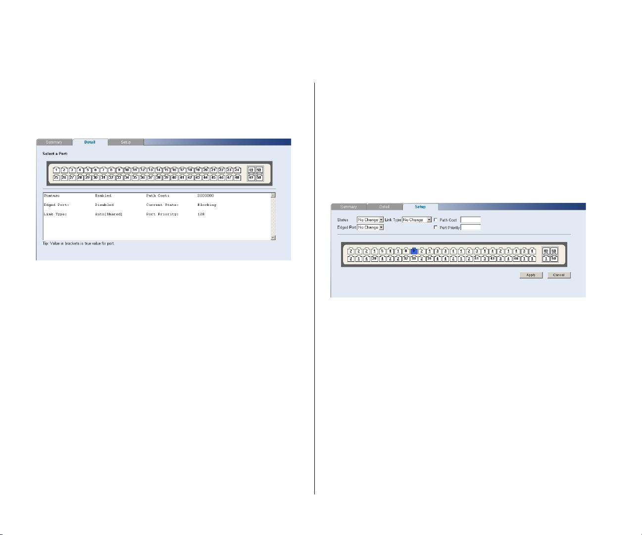
50 CHAPTER 4: CONFIGURING THE SWITCH
Detail
Use the Detail tab to display detailed spanning tree
information for a port.
Figure 45 Spanning Tree Detail Screen
Setup
Use the Setup tab to configure the spanning tree
settings for each port. The following options are
available:
■ Status – Enables and disables spanning tree for the
port.
■ Edged Port – Enables and disables edged port for
the port.
■ Link Type – Choose between Point-to-Point,
Shared, or Auto for the link type.
■ Path Cost – The path cost is used to determine the
best path between devices. The path cost method
is used to determine the range of values that can
be assigned to each interface.
■ Port Priority – Used in selecting the root device,
root port, and designated port. The device with
the highest priority becomes the STA root device.
However, if all devices have the same priority, the
device with the lowest MAC address will then
become the root device.
If you modify any of these settings, click Apply to save
your changes.
Figure 46 Spanning Tree Setup Screen
Port Mirroring
The Switch allows you to monitor traffic going in and
out of a particular port. For traffic monitoring to
work, you need to attach a network analyzer to one
port and use it to monitor the traffic of other ports in
the stack.
To set up traffic monitoring, you need to set an
analysis port (the port that is connected to the
analyzer), and a monitor port (the port that is to be
monitored). Once the pair is defined, and you enable
traffic monitoring, the Switch takes all the traffic
going in and out of the monitor port and copies it to
the analysis port.
Page 51
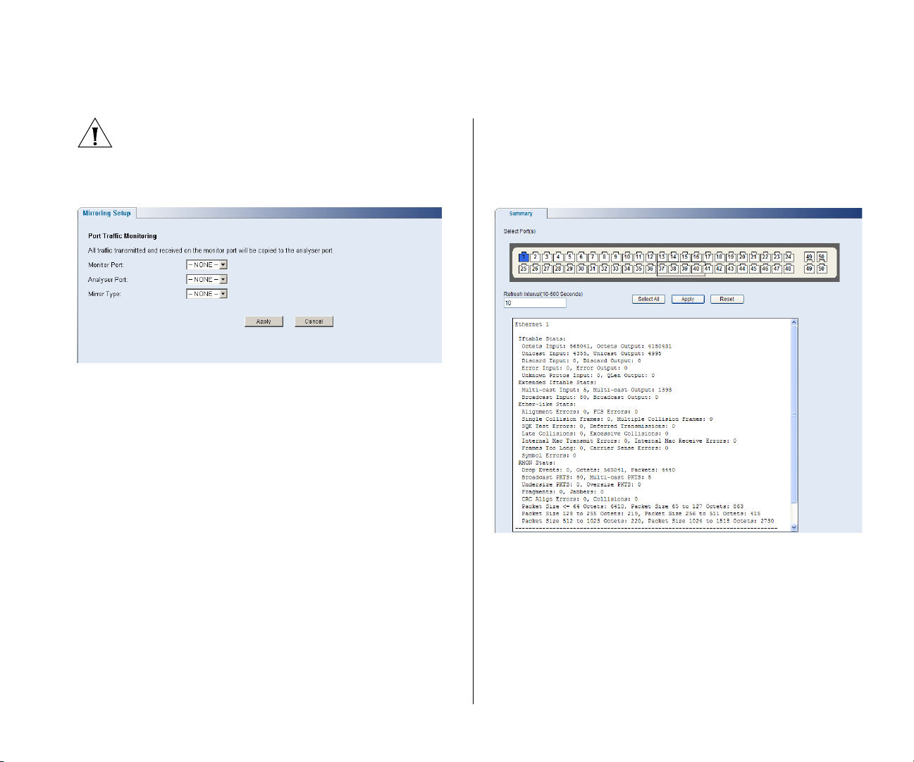
Configuring Port Settings 51
CAUTION: The analyzer port should have a higher
bandwidth than the mirror port. Otherwise, the
Switch may not be able to copy all traffic effectively
during periods of high traffic.
Figure 47 Port Mirroring Screen
To set up port mirroring:
1 Connect a network analyzer to a port.
2 Access the Web interface. Click Port, then Port
Mirroring on the menu. The Port Monitoring Setup
Screen appears.
3 Select the port number, under Monitor Port, which
you want to monitor. Traffic to and from this port will
be forwarded to the analyser port.
4 Select the port number, under Analyser Port, to which
you connected the network analyzer. Traffic to and
from the selected mirrored port will be forwarded to
this port.
5 Under Mirror Type, select to monitor incoming traffic,
outgoing traffic, or both.
6 Click Apply.
Statistics
The Switch allows you to display detailed statistics of
one, several, or all ports.
Figure 48 Port Statistics Screen
To display statistics for a port:
1 Access the Web interface. Click Port, then Statistics
on the menu. The Port Statistics Screen appears.
2 Select one port, multiple ports, or choose Select All,
and enter a refresh interval.
3 Click Apply.
4 Click Reset to clear all counters for the selected
port(s).
Page 52
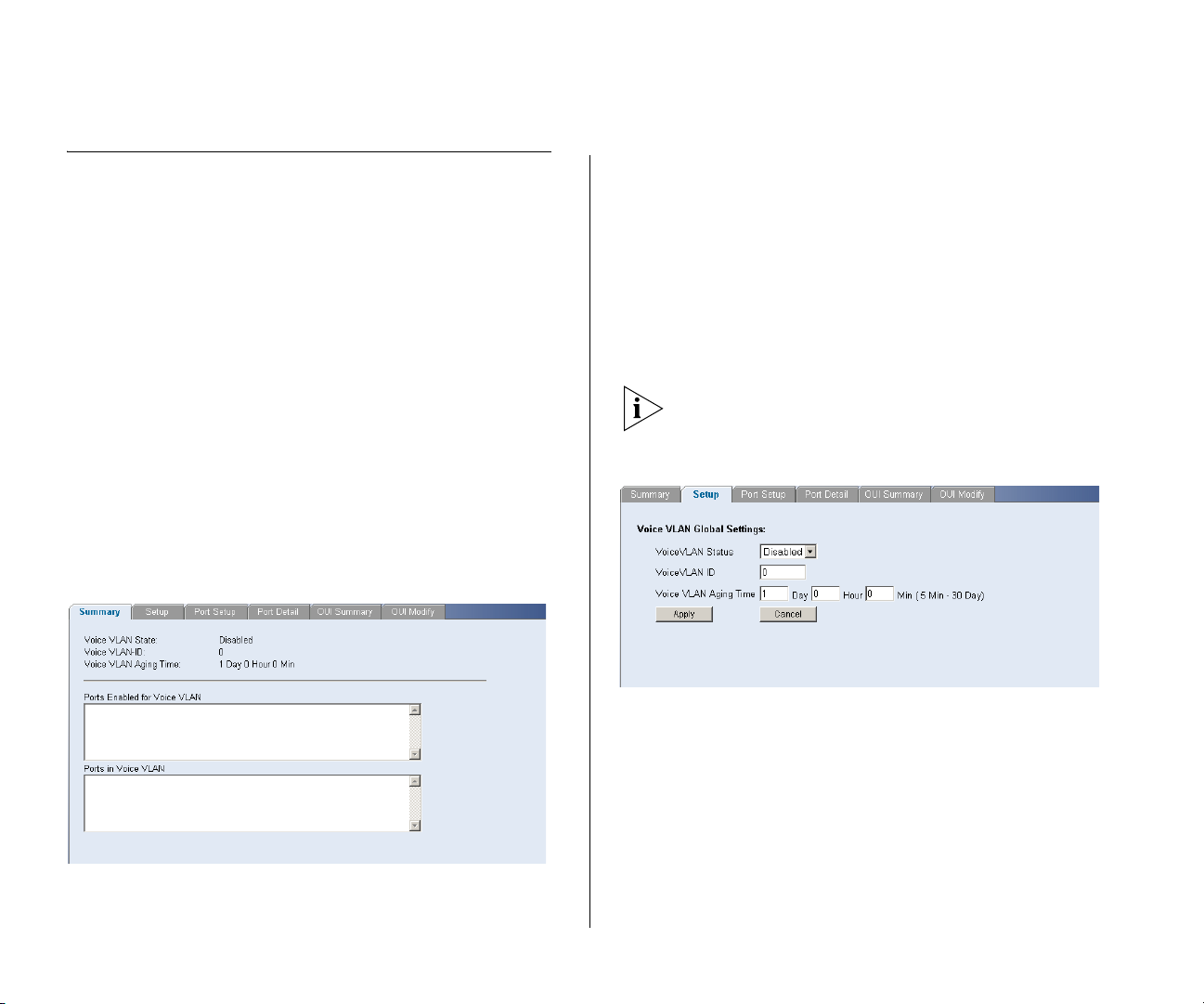
52 CHAPTER 4: CONFIGURING THE SWITCH
QoS VoIP Traffic Settings
Using the Web interface, you can configure the Voice
over Internet Protocol (VoIP) settings.
The QoS VoIP Traffic Setting menu includes six tabs:
■ Summary
■ Setup
■ Port Setup
■ Port Detail
■ OUI Summary
■ OUI Modify
Summary
Use the Summary tab to display the global settings
for the Voice VLAN.
Figure 49 QoS VoIP Summary Screen
Setup
Use the Setup tab to configure the global settings for
the Voice VLAN. The following options are available:
■ Voice VLAN Status – Enable or disable Voice VLAN
for the switch.
■ Voice VLAN ID – Input the Voice VLAN ID for the
switch.
■ Voice VLAN Aging Time – Input the aging time.
You must first create a VLAN from the VLAN Setup
page before you can assign and configure a Voice
VLAN.
Figure 50 QoS VoIP Setup Screen
Port Setup
Use the Port Setup tab to configure the port or trunk
setting for Voice VLAN. The following options are
available:
■ Voice VLAN Port Mode – Select between None,
Manual, or Auto.
■ Voice VLAN Port Security – Enable or disable the
security.
Page 53
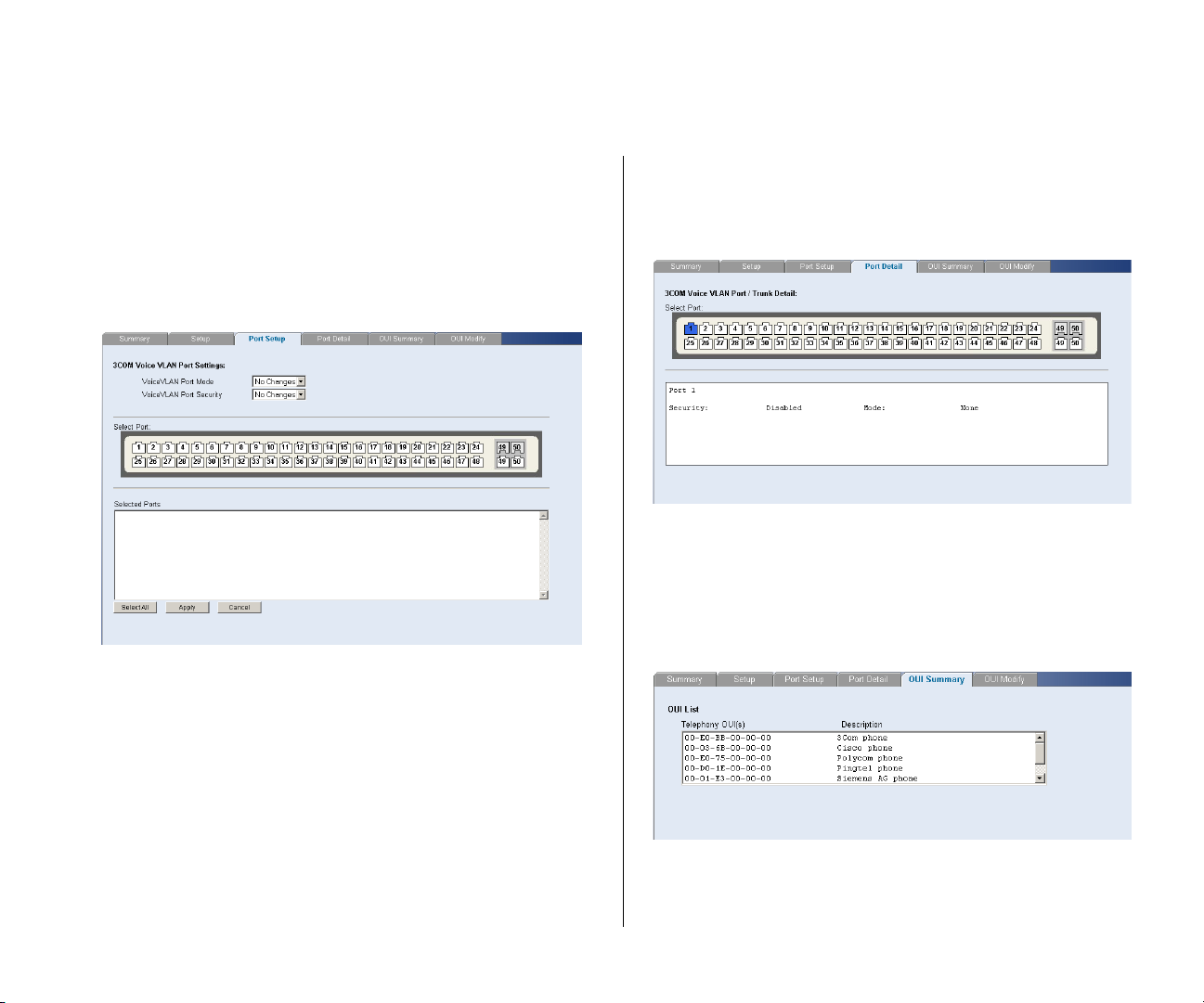
QoS VoIP Traffic Settings 53
To configure the Voice VLAN settings for the ports:
1 Select Voice VLAN Mode and Security settings.
2 Select the ports you would like to apply these settings
to.
3 Click Apply.
Figure 51 QoS Port Setup Screen
Port Detail
Use the Port Detail tab to display the Voice VLAN
information for selected ports.
Figure 52 QoS Port Detail Screen
OUI Summary
Use the OUI Summary tab to display the list of
Organizational Unique Identifier for a company and
their description.
Figure 53 QoS OUI Summary Screen
Page 54
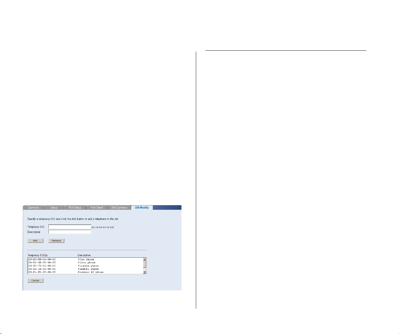
54 CHAPTER 4: CONFIGURING THE SWITCH
OUI Modify
Use the OUI Modify tab to add to the list of
Organizational Unique Identifier. The following
options are available:
■ Telephony OUI – Input a new company identifier to
add to the list.
■ Description – Input a description for the new
company identifier.
To add to the OUI list:
1 Enter a Telephony OUI and description.
2 Click Add.
To remove an OUI from the list:
1 Select a Telephony OUI from the list.
2 Click Remove.
Figure 54 QoS OUI Modify Screen
Security
Using the Web interface, you can configure the
RADIUS Client and 802.1X settings.
The Security menu includes two items:
■ RADIUS Client
■ 802.1X Settings
RADIUS Client
Remote Authentication Dial-in User Service (RADIUS)
is a logon authentication protocol that uses software
running on a central server to control access to
RADIUS-aware devices on the network. An
authentication server contains a database of multiple
user name/password pairs with associated privilege
levels for each user or group that require
management access to a switch.
The RADIUS Client menu includes two tabs:
■ Detail
■ Configure
Page 55
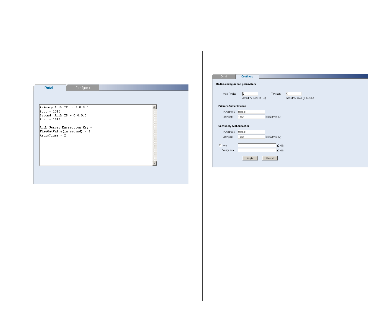
Security 55
Detail
Use the Detail tab to display the RADIUS Client
settings.
Figure 55 RADIUS Client Detail Screen
Configure
Use the Configure tab to configure the RADIUS
settings. The following parameters are available:
■ Max Retries – Sets the number of retries of sending
authentication requests.
After you have filled in the parameters, click Apply to
save your changes.
Figure 56 RADIUS Client Configure Screen
802.1X Settings
The IEEE 802.1X (dot1x) standard defines a
port-based access control procedure that prevents
unauthorized access to a network by requiring users
to first submit credentials for authentication.
The 802.1X settings menu includes three tabs:
■ Timeout – Sets the interval between sending
authentication requests.
■ IP Address – The IP address of the RADIUS server.
■ UDP port – The RADIUS server UDP port used for
authentication messages.
■ Key – Sets the RADIUS encryption key.
■ Summary
■ Detail
■ Setup
Page 56
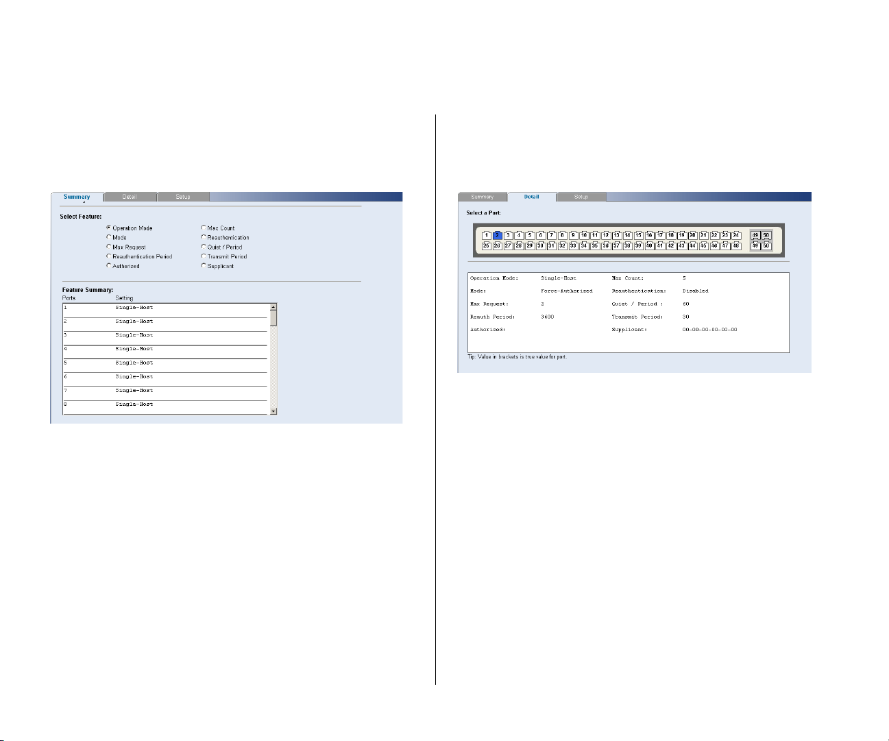
56 CHAPTER 4: CONFIGURING THE SWITCH
Summary
Use the Summary tab to display the 802.1X
authentication settings.
Figure 57 802.1X Summary Screen
Detail
Use the Detail tab to display detailed 802.1X
authentication information for a port.
Figure 58 802.1X Detail Screen
Setup
Use the Setup tab to configure the 802.1X
authenticaion settings. The following fields are
available:
■ System Authentication – Sets the global setting for
802.1X. (Default: Disabled)
■ Operation Mode – Allows single or multiple hosts
(clients) to connect to an 802.1X-authorized port.
(Options: Single-Host, Multi-Host; Default:
Single-Host)
■ Mode – Sets the authentication mode to one of
the following options:
■ Auto – Requires a dot1x-aware client to be
authorized by the authentication server. Clients
that are not dot1x-aware will be denied access.
Page 57
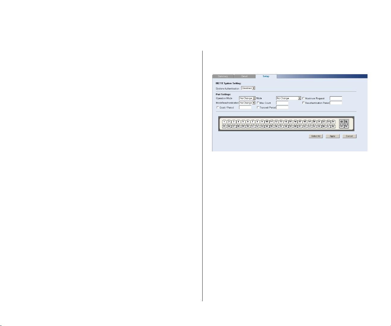
Security 57
■ Force-Authorized – Forces the port to grant
access to all clients, either dot1x-aware or
otherwise.
■ Force-Unauthorized – Forces the port to deny
access to all clients, either dot1x-aware or
otherwise.
■ Maximum Request – Sets the maximum number of
times the switch port will retransmit an EAP
request packet to the client before it times out the
authentication session. (Range: 1-10; Default 2)
■ Mode Reauthentication – Sets the client to be
re-authenticated after the interval specified by the
Re-authentication Period. Re-authentication can be
used to detect if a new device is plugged into a
switch port. (Default: Disabled)
■ Max Count – The maximum number of hosts that
can connect to a port when the Multi-Host
operation mode is selected. (Range: 1-1024;
Default: 5)
■ Reauthentication Period – Sets the time period
after which a connected client must be
re-authenticated. (Range: 1-65535 seconds;
Default: 3600 seconds)
After you have filled in the parameters, click Apply to
save your changes.
Figure 59 802.1X Setup Screen
■ Quiet Period – Sets the time that a switch port
waits after the Max Request Count has been
exceeded before attempting to acquire a new
client. (Range: 1-65535 seconds; Default: 60
seconds)
■ Transmit Period – Sets the time period during an
authentication session that the switch waits before
re-transmitting an EAP packet. (Range: 1-65535;
Default: 30 seconds)
Page 58
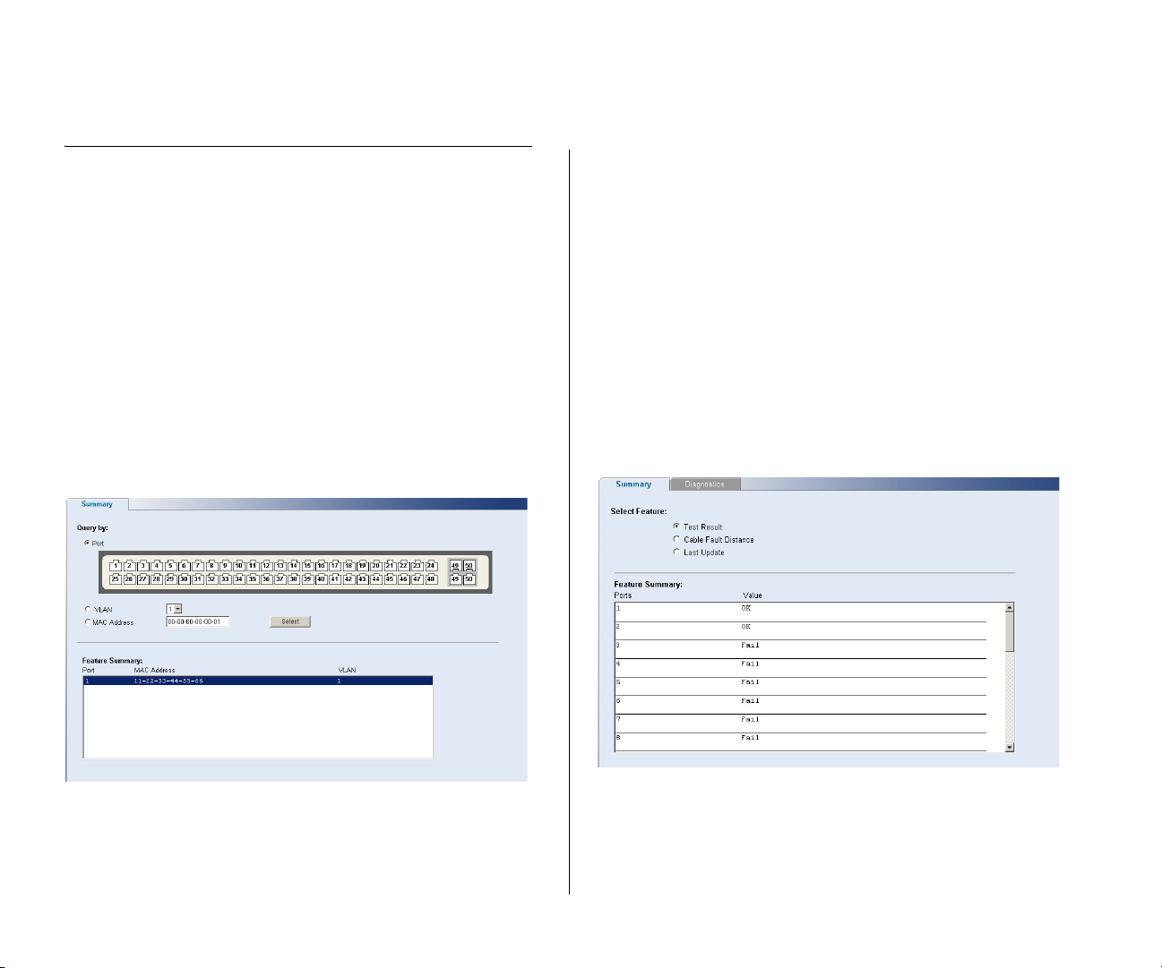
58 CHAPTER 4: CONFIGURING THE SWITCH
Monitoring
Using the Web interface, you can display address
table information and cable diagnostics.
The Monitoring menu includes two items:
■ Address Table
■ Cable Diagnostics
Address Table
Use the Address Table Summary screen to display the
Address Table information. You can query by selecting
a port, choosing a VLAN, or entering in a MAC
Address, then click Select.
Figure 60 Address Table Screen
Cable Diagnostics
The Switch provides a cable diagnostic utility, which
helps you detect and resolve issues with the attached
cables.
The Cable Diagnostics menu includes two tabs:
■ Summary
■ Diagnostics
Summary
Use the Summary tab to display information on Test
Result, Cable Fault Distance, or Last Update for every
port on the switch.
Figure 61 Cable Diagnostic Summary Screen
Page 59
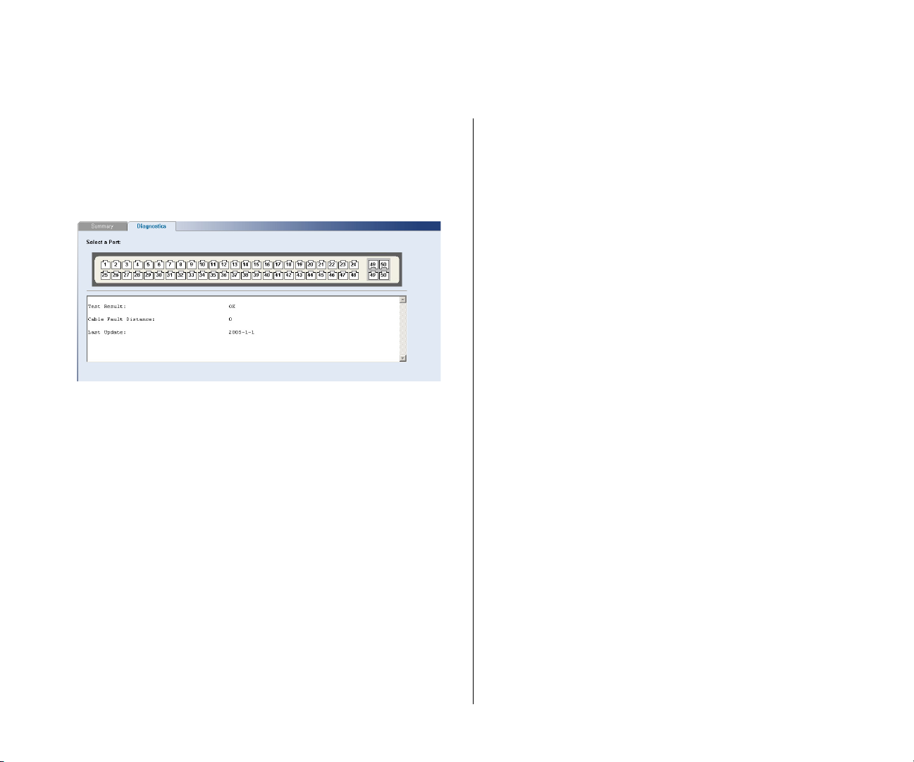
Diagnostics
Use the Diagnostics tab to display individual port
information on Test Result, Cable Fault Distance, and
Last Update.
Figure 62 Cable Diagnostic Screen
Monitoring 59
Page 60

60 CHAPTER 4: CONFIGURING THE SWITCH
Page 61
5
TROUBLESHOOTING
This chapter lists some issues that you may encounter
while installing, using, and managing the Switch,
with suggested courses of corrective action to take.
If you encounter an issue that is not listed here and
you cannot solve it, check the 3Com Knowledgebase
at
http://knowledgebase.3com.com before contacting
your local technical support representative.
For more information on how to obtain support for
your Switch, refer to Appendix A
.
Resetting to Factory Defaults
If the Switch does not operate normally or if the
firmware becomes corrupted, you can reset the
Switch to factory defaults.
CAUTION: Resetting the Switch to factory defaults
erases all your settings. You will need to reconfigure
the Switch after you reset it.
To reset the Switch to its factory defaults:
1 Using the tip of a pen (or a similar object), press the
Recovery button on the rear panel of the Switch. See
Figure 1
for illustration.
4 Reset the Switch either by:
■ Accessing the Web interface using Discovery, and
then pressing the RESET button on the Initialize tab
of the Administration menu. After you click RESET,
a confirmation message appears. Click OK to con-
firm.
■ Powering off the Switch, and then powering it
back on.
The Switch will perform automatic IP configuration
after you reset it. See “
on page 29
for more information.
Forgotten Password
If you forget the password to the Web interface after
you set it, you will need to reset the Switch to regain
access. See “
page 61
After resetting the Switch, log on to the Web interface using the default admin account settings:
■ User name – admin
■ Password – blank (no password)
Resetting to Factory Defaults” on
for instructions.
Automatic IP Configuration”
2 Power off the Switch, and then power it back on,
while keeping the Recovery button pressed.
3 Release the Recovery button.
Page 62

62 CHAPTER 5: TROUBLESHOOTING
Forgotten Static IP Address
If you forget the static IP address that you assigned to
the Switch and you need to access the Web interface,
use the Discovery application to automatically detect
the IP address and connect to the interface.
For information on using the Discovery application,
refer to “
page 21
Running the Discovery Application” on
.
Solving LED Issues
This section lists some issues that are related to the
LEDs on the front panel of the Switch. For
information on basic LED checks, refer to the
following topics in Chapter 1
■ (4) Module Active LEDs
■ (3) Link/Activity LEDs
■ (5) Power LED
A link is connected, but the Link/Activity LED for
the port is off.
There is a problem with this connection. Verify that:
■ The device being connected to is powered on and
operating correctly.
■ The cable is connected at both ends.
■ The cable is not damaged.
■ If the connection is to a workstation, that the
workstation's network interface is installed and
configured correctly.
■ The correct category of cable is being used for the
required link speed. Category 3 cables can be used
for 10BASE-T operation only. Category 5 cable is
required for 100BASE-TX or 1000BASE-T. 3Com
recommends Category 5e or 6 cables for
1000BASE-T operation.
A fiber cable is connected, but the Module
Active LED is off.
Verify that:
■ The fiber cable is in good condition.
■ The SFP module is correctly inserted.
■ A 3Com SFP module is being used. Refer to
“
Approved SFP Transceivers” on page 18 for
:
details.
■ The equipment at the far end is installed and cor-
rectly configured.
The Link/Activity LED is on, but network performance is poor
The Switch supports full-duplex autonegotiation. If
the connected device does not support
autonegotiation, ensure that it is configured for
half-duplex operation only. If the connected device
has autonegotiation disabled or overridden, and is
configured as full-duplex, the Switch will configure
the link as half-duplex, causing a mismatch that will
reduce network performance when data is
transmitting and receiving simultaneously on the
same link.
Page 63

Ensure that the connected device has either:
■ Autonegotiation enabled, or
■ The ports are configured for half-duplex operation
All ports appear to show continual activity.
There may be broadcast storms on the network.
Remove port connections one at a time, waiting a
few seconds between each port. If the LEDs go off
after removing a port connection, the device that was
connected to that port is introducing an excessive
amount of broadcast frames to the network. Some
pieces of network equipment operate by sending out
broadcast frames regularly.
Refer to the documentation that accompanies the
device for information on disabling the broadcast
operation.
If the Problem Persists
If the problem persists and the unit still does not
operate successfully, contact your 3Com network
supplier with the following information before
returning the unit:
■ Product number and serial number (printed on a
label supplied with the unit).
If the Problem Persists 63
■ A brief description of the issue
Page 64

64 CHAPTER 5: TROUBLESHOOTING
Page 65

A
OBTAINING SUPPORT FOR YOUR PRODUCT
Register Your Product
Warranty and other service benefits start from the
date of purchase, so it is important to register your
product quickly to ensure you get full use of the
warranty and other service benefits available to you.
Warranty and other service benefits are enabled
through product registration. Register your product at
http://eSupport.3com.com/. 3Com eSupport
services are based on accounts that you create or
have authorization to access. First time users must
apply for a user name and password that provides
access to a number of eSupport features including
Product Registration, Repair Services, and Service
Request. If you have trouble registering your product,
please contact 3Com Global Services for assistance.
Purchase Value-Added Services
To enhance response times or extend warranty
benefits, contact 3Com or your authorized 3Com
reseller. Value-added services like 3Com Express
and Guardian
support, software upgrades, onsite assistance or
advance hardware replacement. Experienced
engineers are available to manage your installation
with minimal disruption to your network. Expert
assessment and implementation services are offered
to fill resource gaps and ensure the success of your
SM
can include 24x7 telephone technical
SM
networking projects. More information on 3Com
maintenance and Professional Services is available at
http://www.3com.com/
Contact your authorized 3Com reseller or 3Com for a
complete list of the value-added services available in
your area.
Troubleshoot Online
You will find support tools posted on the 3Com web
site at
http://www.3com.com/
3Com Knowledgebase helps you troubleshoot
3Com products. This query-based interactive tool is
located at
contains thousands of technical solutions written by
3Com support engineers.
http://knowledgebase.3com.com and
Access Software Downloads
Software Updates are the bug fix / maintenance
releases for the version of software initially purchased
with the product. In order to access these Software
Updates you must first register your product on the
3Com web site at
First time users will need to apply for a user name and
password. A link to software downloads can be found
http://eSupport.3com.com/.
Page 66

66 APPENDIX A: OBTAINING SUPPORT FOR YOUR PRODUCT
at http://eSupport.3com.com/, or under the
Product Support heading at
http://www.3com.com/
Software Upgrades are the software releases that
follow the software version included with your original product. In order to access upgrades and related
documentation you must first purchase a service contract from 3Com or your reseller.
Telephone Technical Support and Repair
To obtain telephone support as part of your warranty
and other service benefits, you must first register your
product at
Warranty and other service benefits start from the
date of purchase, so it is important to register your
product quickly to ensure you get full use of the warranty and other service benefits available to you.
When you contact 3Com for assistance, please have
the following information ready:
■ Product model name, part number, and serial
number
http://eSupport.3com.com/
To send a product directly to 3Com for repair, you
must first obtain a return authorization number
(RMA). Products sent to 3Com, without authorization
numbers clearly marked on the outside of the package, will be returned to the sender unopened, at the
sender’s expense. If your product is registered and
under warranty, you can obtain an RMA number
online at
users will need to apply for a user name and password.
Contact Us
3Com offers telephone, e-mail and internet access to
technical support and repair services. To access these
services for your region, use the appropriate
telephone number, URL or e-mail address from the list
below.
Telephone numbers are correct at the time of publication. Find a current directory of support telephone
numbers posted on the 3Com web site at
http://csoweb4.3com.com/contactus/
http://eSupport.3com.com/. First time
■ Proof of purchase, if you have not pre-registered
your product
■ A list of system hardware and software, including
revision level
■ Diagnostic error messages
■ Details about recent configuration changes, if
applicable
Page 67

Contact Us 67
.
Country Telephone Number
Asia, Pacific Rim Telephone Technical Support and
Repair
Australia
Hong Kong
India
Indonesia
Japan
Malaysia
New Zealand
Pakistan
Philippines
P.R. of China
Singapore
S. Korea
Ta iw a n
Thailand
You can also obtain support in this region using the following
e-mail: [email protected]
Or request a repair authorization number (RMA) by fax using
this number: +65 543 6348
Europe, Middle East, and Africa Telephone Technical
Support and Repair
From anywhere in these
regions, call:
From the following countries, you may use the numbers
shown:
1 800 678 515
800 933 486
+61 2 9424 5179 or
000800 6501111
001 803 61 009
00531 616 439 or
03 3507 5984
1800 801 777
0800 446 398
+61 2 9937 5083
1235 61 266 2602 or
1800 1 888 9469
800 810 3033
800 6161 463
080 333 3308
00801 611 261
001 800 611 2000
+44 (0)1442 435529
Country Telephone Number
Austria
Belgium
Denmark
Finland
France
Germany
Hungary
Ireland
Israel
Italy
Luxembourg
Netherlands
Norway
Poland
Portugal
South Africa
Spain
Sweden
Switzerland
U.K.
You can also obtain support in this region using the following
URL: http://emea.3com.com/support/email.html
Country Telephone Number
01 7956 7124
070 700 770
7010 7289
01080 2783
0825 809 622
01805 404 747
06800 12813
1407 3387
1800 945 3794
199 161346
342 0808128
0900 777 7737
815 33 047
00800 441 1357
707 200 123
0800 995 014
9 021 60455
07711 14453
08488 50112
0870 909 3266
Latin America Telephone Technical Support and
Repair
From the Caribbean, Central and South America, call:
Page 68

68 APPENDIX A: OBTAINING SUPPORT FOR YOUR PRODUCT
Country Telephone Number
Antigua
Argentina
Aruba
Bahamas
Barbados
Belize
Bermuda
Bonaire
Brazil
Cayman
Chile
Colombia
Costa Rica
Curacao
Ecuador
Dominican Republic
Guatemala
Haiti
Honduras
Jamaica
Martinique
Mexico
Nicaragua
Panama
Paraguay
Peru
Puerto Rico
Salvador
Trinidad and Tobago
Uruguay
Venezuela
Virgin Islands
1 800 988 2112
0 810 444 3COM
1 800 998 2112
1 800 998 2112
1 800 998 2112
52 5 201 0010
1 800 998 2112
1 800 998 2112
0800 13 3COM
1 800 998 2112
AT&T +800 998 2112
AT&T +800 998 2112
AT&T +800 998 2112
1 800 998 2112
AT&T +800 998 2112
AT&T +800 998 2112
AT&T +800 998 2112
57 1 657 0888
AT&T +800 998 2112
1 800 998 2112
571 657 0888
01 800 849CARE
AT&T +800 998 2112
AT&T +800 998 2112
54 11 4894 1888
AT&T +800 998 2112
1 800 998 2112
AT&T +800 998 2112
1 800 998 2112
AT&T +800 998 2112
AT&T +800 998 2112
57 1 657 0888
Country Telephone Number
You can also obtain support in this region using the following:
Spanish speakers, enter the URL:
http://lat.3com.com/lat/support/form.html
Portuguese speakers, enter the URL:
http://lat.3com.com/br/support/form.html
English speakers in Latin America should send e-mail to:
US and Canada Telephone Technical Support and Repair
1 800 876 3266
Page 69

B
SAFETY INFORMATION
Important Safety Information
Please refer to the safety information found in the
3Com Switch Family Safety and Regulatory Information manual included with this product.
You can find the 3Com Switch Family Safety and
Regulatory Information manual on the product
CD-ROM that was included with your switch. You can
also download the safety manual from the 3Com
Web site: www.3Com.com
Page 70

70 APPENDIX B: SAFETY INFORMATION
Page 71

C
TECHNICAL INFORMATION
Related Standards
The 3Com Baseline Switch 2250 Plus has been
designed to the following standards:
Functional ISO 8802-3, IEEE 802.3 (Ethernet),
MAC Address 4096
Safety UL/CUL (UL60950-1, CSA22.2 No
EMC Emissions EN 55022 Class A, FCC Part 15
Immunity EN 55024
Environmental
Operating Temperature 0–40 °C (32–104 °F)
Humidity 0–95% (non-condensing)
Standard EN 60068 (IEC 68)—various parts
IEEE 802.3u (Fast Ethernet), IEEE
802.3ab (Gigabit Ethernet), IEEE
802.3x (Flow Control), IEEE 802.1D
(Bridging)
60950-1), TUV/GS (EN60950-1),
IEC60950-1
Subpart B Class A, ICES-003 Class
A, VCCI Class A, AS/NZS 3548
Class A, CNS 13438 Class A
Physical
Width 440 mm (17.3 in.)
Depth 215 mm (8.5 in.)
Height 41 mm (1.6 in.) or 1U
Weight 3.1 kgs (6.83 lbs)
Mounting Free standing, or 19 in. rack
Electrical
Power Inlet IEC 320
AC Line Frequency 50/60 Hz
Input Voltage 100–240 VAC
Current Rating 2 amperes (maximum)
Maximum Power Consumption
Maximum Power Dissipation
mounted using the mounting kit
supplied
56 watts
184.3 BTU/hr
Page 72

72 APPENDIX C: TECHNICAL INFORMATION
Page 73

GLOSSARY
10BASE-T
The IEEE specification for 10 Mbps Ethernet over
Category 3, 4 or 5 twisted pair cable.
100BASE-TX
The IEEE specification for 100 Mbps Fast Ethernet
over Category 5 twisted-pair cable.
1000BASE-LX
IEEE 802.3z specification for Gigabit Ethernet over
9/125 micron core single-mode fiber cable.
1000BASE-SX
IEEE 802.3z specification for Gigabit Ethernet over
two strands of 50/125 or 62.5/125 micron core
multimode fiber cable.
1000BASE-T
IEEE 802.3ab specification for Gigabit Ethernet over
100-ohm Category 5, 5e or 6 twisted-pair cable
(using all four wire pairs).
autonegotiation
Autonegotiation is where two devices sharing a link,
automatically configure to use the best common
speed. The order of preference (best first) is:
1000BASE-T full-duplex, 100BASE-TX full-duplex,
100BASE-TX half-duplex, 10BASE-T full-duplex, and
10BASE-T half-duplex. Autonegotiation is defined in
the IEEE 802.3 standard for Ethernet and is an
operation that takes place in a few milliseconds.
Autonegotiation must be enabled for the
1000BASE-T ports to operate at 1000 Mbps,
full-duplex.
bandwidth
The information capacity (measured in bits per
second) that a channel can transmit. The bandwidth
of Ethernet is 10 Mbps, the bandwidth of Fast
Ethernet is 100 Mbps and Gigabit Ethernet is 1000
Mbps.
category 3 cable
One of five grades of Twisted Pair (TP) cabling defined
by the EIA/TIA-568 standard. Category 3 is voice
grade cable and can only be used in Ethernet
networks (10BASE-T) to transmit data at speeds of up
to 10 Mbps.
category 5 cable
One of five grades of Twisted Pair (TP) cabling defined
by the EIA/TIA-568 standard. Category 5 can be used
in Ethernet (10BASE-T) and Fast Ethernet networks
(100BASE-TX) and can transmit data at speeds of up
to 100 Mbps. Category 5 cabling is better to use for
network cabling than Category 3, because it supports
both Ethernet (10 Mbps) and Fast Ethernet (100
Mbps) speeds.
Page 74

74 GLOSSARY
category 5e cables
One of five grades of Twisted Pair (TP) cabling defined
by the EIA/TIA-568 standard. Category 5e can be
used in Ethernet (10BASE-T), Fast Ethernet
(100BASE-TX) and Gigabit Ethernet (1000BASE-T)
networks, and can transmit data at speeds of up to
1000 Mbps.
category 6 cable
One of five grades of Twisted Pair (TP) cabling defined
by the EIA/TIA-568-B standard. Category 6 can be
used in Ethernet (10BASE-T), Fast Ethernet
(100BASE-TX) and Gigabit Ethernet (1000BASE-T)
networks, and can transmit data at speeds of up to
1000 Mbps.
client
The term used to describe the desktop PC that is
connected to your network.
DHCP
Dynamic Host Configuration Protocol. This protocol
automatically assigns an IP address for every
computer on your network. Windows 95, Windows
98 and Windows NT 4.0 contain software that
assigns IP addresses to workstations on a network.
These assignments are made by the DHCP server
software that runs on Windows NT Server.
Ethernet
A LAN specification developed jointly by Xerox, Intel
and Digital Equipment Corporation. Ethernet
networks use CSMA/CD to transmit packets at a rate
of 10 Mbps and 100 Mbps over a variety of cables.
Ethernet address
See MAC address.
Fast Ethernet
An Ethernet system that is designed to operate at 100
Mbps.
Gigabit Ethernet
An Ethernet system that is designed to operate at
1000 Mbps.
full-duplex
A system that allows packets to be transmitted and
received at the same time and, in effect, doubles the
potential throughput of a link.
half-duplex
A system that allows packets to be transmitted and
received, but not at the same time. Half-duplex is not
supported for 1000 Mbps. Contrast with full-duplex.
IEEE
Institute of Electrical and Electronics Engineers. This
American organization was founded in 1963 and sets
standards for computers and communications.
IEEE 802.1D
Specifies a general method for the operation of MAC
bridges, including the Spanning Tree Protocol.
IEEE 802.1Q
VLAN Tagging - Defines Ethernet frame tags that
carry VLAN information. It allows switches to assign
endstations to different virtual LANs, and defines a
Page 75

GLOSSARY 75
standard way for VLANs to communicate across
switched networks.
IEEE 802.1p
An IEEE standard for providing quality of service (QoS)
in Ethernet networks. The standard uses packet tags
that define up to eight traffic classes and allows
switches to transmit packets based on the tagged
priority value.
IEEE 802.3ad
A standard that defines link aggregation. 802.3ad is
now incorporated into the relevant sections of the
IEEE Std. 802.3-2002.
IETF
Internet Engineering Task Force. An organization
responsible for providing engineering solutions for
TCP/IP networks. In the network management area,
this group is responsible for the development of the
SNMP protocol.
IP
Internet Protocol. IP is a layer 3 network protocol that
is the standard for sending data through a network.
IP is part of the TCP/IP set of protocols that describe
the routing of packets to addressed devices. An IP
address consists of 32 bits divided into two or three
fields: a network number and a host number or a
network number, a subnet number, and a host
number.
IP Address
Internet Protocol Address. A unique identifier for a
device attached to a network using TCP/IP. The
address is written as four octets separated with
periods (full-stops), and is made up of a network
section, an optional subnet section and a host
section.
LAN
Local Area Network. A network of end stations (such
as PCs, printers, servers) and network devices (hubs
and switches) that cover a relatively small geographic
area (usually not larger than a floor or building). LANs
are characterized by high transmission speeds over
short distances (up to 1000 meters).
Layer 2
Data Link layer in the ISO 7-Layer Data
Communications Protocol. This is related directly to
the hardware interface for the network devices and
passes on traffic based on MAC addresses.
link aggregation
See Trunking.
MAC
Media Access Control. A protocol specified by the
IEEE for determining which devices have access to a
network at any one time.
MAC address
Media Access Control Address. Also called the
hardware, physical, or Ethernet address. A layer 2
address associated with a particular network device.
Page 76

76 GLOSSARY
network
ping
protocol
RJ-45
server
Most devices that connect to a LAN have a MAC
address assigned to them as they are used to identify
other devices on a network. MAC addresses are 6
bytes long.
A network is a collection of computers and other
computer equipment that are connected for the
purpose of exchanging information or sharing
resources. Networks vary in size, some are within a
single room, others span continents.
Packet Internet Groper. An internet utility used to
determine whether a particular IP address is online. It
is used to test and debug a network by sending out a
packet and waiting for a response.
A set of rules for communication between devices on
a network. The rules dictate format, timing,
sequencing and error control.
A standard connector used to connect Ethernet
networks. The “RJ” stands for “registered jack.”
A computer on a network that is shared by multiple
end stations. Servers provide end stations with access
to shared network services such as computer files and
printer queues.
SFP
Small Form Factor Pluggable (SFP) Connectors are
based on an open standard that enables hot
swapping of various types of fiber optic and
copper-based transceivers into the host equipment.
subnet address
An extension of the IP addressing scheme that allows
a site to use a single IP network address for multiple
physical networks.
subnet mask
A subnet mask, which may be a part of the TCP/IP
information provided by your ISP, is a set of four
numbers configured like an IP address. It is used to
create IP address numbers used only within a
particular network (as opposed to valid IP address
numbers recognized by the Internet, which must
assigned by InterNIC).
subnet
A network that is a component of a larger network.
switch
A device that interconnects several LANs to form a
single logical LAN that comprises of several LAN
segments. Switches are similar to bridges, in that they
connect LANs of a different type; however they
connect more LANs than a bridge and are generally
more sophisticated.
Page 77

TCP/IP
Transmission Control Protocol/Internet Protocol. This
is the name for two of the most well-known protocols
developed for the interconnection of networks.
Originally a UNIX standard, TCP/IP is now supported
on almost all platforms, and is the protocol of the
Internet.
TCP relates to the content of the data travelling
through a network — ensuring that the information
sent arrives in one piece when it reaches its
destination. IP relates to the address of the end
station to which data is being sent, as well as the
address of the destination network.
traffic monitoring
Enables the monitoring of port traffic by attaching a
network analyzer to one switch port, in order to
monitor the traffic of other ports on the Switch.
trunking
A method which specifies how to create a single
high-speed logical link that combines several
lower-speed physical links.
GLOSSARY 77
VLAN
Virtual LAN. A collection of network nodes that share
the same collision domain regardless of their physical
location or connection point in the network. A VLAN
serves as a logical workgroup with no physical
barriers, and allows users to share information and
resources as though located on the same LAN.
Page 78

78 GLOSSARY
Page 79

INDEX
Numbers
1000BASE-LX 73
1000BASE-SX 73
1000BASE-T 73
100BASE-TX 73
10BASE-T 73
A
auto IP configuration 29
default IP address 29
default mask 29
autonegotiation 7
autosensing 7
B
bandwidth 73
C
client 74
configuration
overview 27
connecting
network device 17
SFP transceivers 18
conventions
notice icons, About This Guide 5
text, About This Guide 5
D
DHCP 74
Discovery 21
dynamic host control protocol See DHCP
E
Ethernet 74
F
Fast Ethernet 74
forgotten IP address 61
forgotten password 61
free-standing 14
front panel
Link/Activity LEDs 10
Module Active LEDs 11
Power LED 12
RJ-45 ports 11
self-adhesive pads 12
SFP ports 10
full-duplex 74
G
Gigabit Ethernet 74
H
half-duplex 74
I
IEEE 74
IETF 75
installing 13
IP address
auto configuration 29
modifying 29
IP defined 75
L
LAN defined 75
LED issues 62
LEDs
Link/Activity 10
Module Active 11
Power 12
link aggregation 46
local area network 75
M
MAC address 75
media access control 75
monitoring traffic 50
mounting kit
contents 13
using 14
N
network analyzer 50
network cables
category 3 73
category 5 73
category 5e 74
category 6 74
network defined 76
P
package contents 12
panels
front 9
rear 12
password
Page 80

80 INDEX
changing 32, 34
default (blank) 32
setting 28
physical features 9
port settings
configuring 44, 52, 54
ports
RJ-45 11
SFP 8, 10
positioning 13
POST 16
powering on 16
power-on self-test See POST
protocol defined 76
R
rack-mounting 14
rear panel
power supply 12
Recovery button 12
resetting to factory defaults 61
RJ-45
defined 76
ports 11
S
server defined 76
SFP ports 8, 10
SFP transceivers 18
approved (supported) 18
inserting 18
removing 19
spot checks 19
subnet mask 76
switch defined 76
troubleshooting 61
forgotten IP address 61
forgotten password 61
LED-related issues 62
POST failed 17
trunking See link aggregation
U
user name
default 32
V
viewing
status information 27
VLANs 36
creating 42
maximum supported 36
sample configurations 40
W
Web interface
accessing directly 26
accessing using Discovery 21
buttons 25
connecting 21
logging on 23
menu 23
navigating 23
requirements for accessing 21
T
TCP/IP 75
defined 77
traffic 77
monitoring 50
Page 81

REGULATORY NOTICES
FCC STATEMENT
This equipment has been tested and found to comply with the limits for a Class A digital
device, pursuant to part 15 of the FCC rules. These limits are designed to provide
reasonable protection against harmful interference when the equipment is operated in
a commercial environment. This equipment generates, uses and can radiate radio
frequency energy and, if not installed and used in accordance with the instructions, may
cause harmful interference to radio communications. Operation of this equipment in a
residential area is likely to cause harmful interference to radio communications, in which
case the user will be required to correct the interference at their own expense.
INFORMATION TO THE USER
If this equipment does cause interference to radio or television reception, which can be
determined by turning the equipment off and on, the user is encouraged to try to
correct the interference by one or more of the following measures:
■ Reorient the receiving antenna.
■ Relocate the equipment with respect to the receiver.
■ Move the equipment away from the receiver.
■ Plug the equipment into a different outlet so that equipment and receiver are on
different branch circuits.
If necessary, the user should consult the dealer or an experienced radio/television
technician for additional suggestions. The user may find the following booklet prepared
by the Federal Communications Commission helpful:
How to Identify and Resolve Radio-TV Interference Problems
This booklet is available from the U.S. Government Printing Office, Washington,
DC 20402, Stock No. 004-000-00345-4.
In order to meet FCC emissions limits, this equipment must be used only with cables
which comply with IEEE 802.3.
CE STATEMENT (EUROPE)
This product complies with the European Low Voltage Directive 73/23/EEC and EMC
Directive 89/336/EEC as amended by European Directive 93/68/EEC/.
VCCI STATEMENT
CSA STATEMENT
This Class A digital apparatus meets all requirements of the Canadian
Interference-Causing Equipment Regulations.
Cet appareil numérique de la classe A respecte toutes les exigences du Règlement sur le
matériel brouilleur du Canada.
 Loading...