

Page 1
3B SCIENTIFIC
Function Generator FG100 (230 V, 50/60 Hz)
Function Generator FG100 (115 V, 50/60 Hz)
1009957 / U8533600-230
1009956 / U8533600-115
Instruction Sheet
11/12 SD/ALF
®
PHYSICS
1. Safety instructions
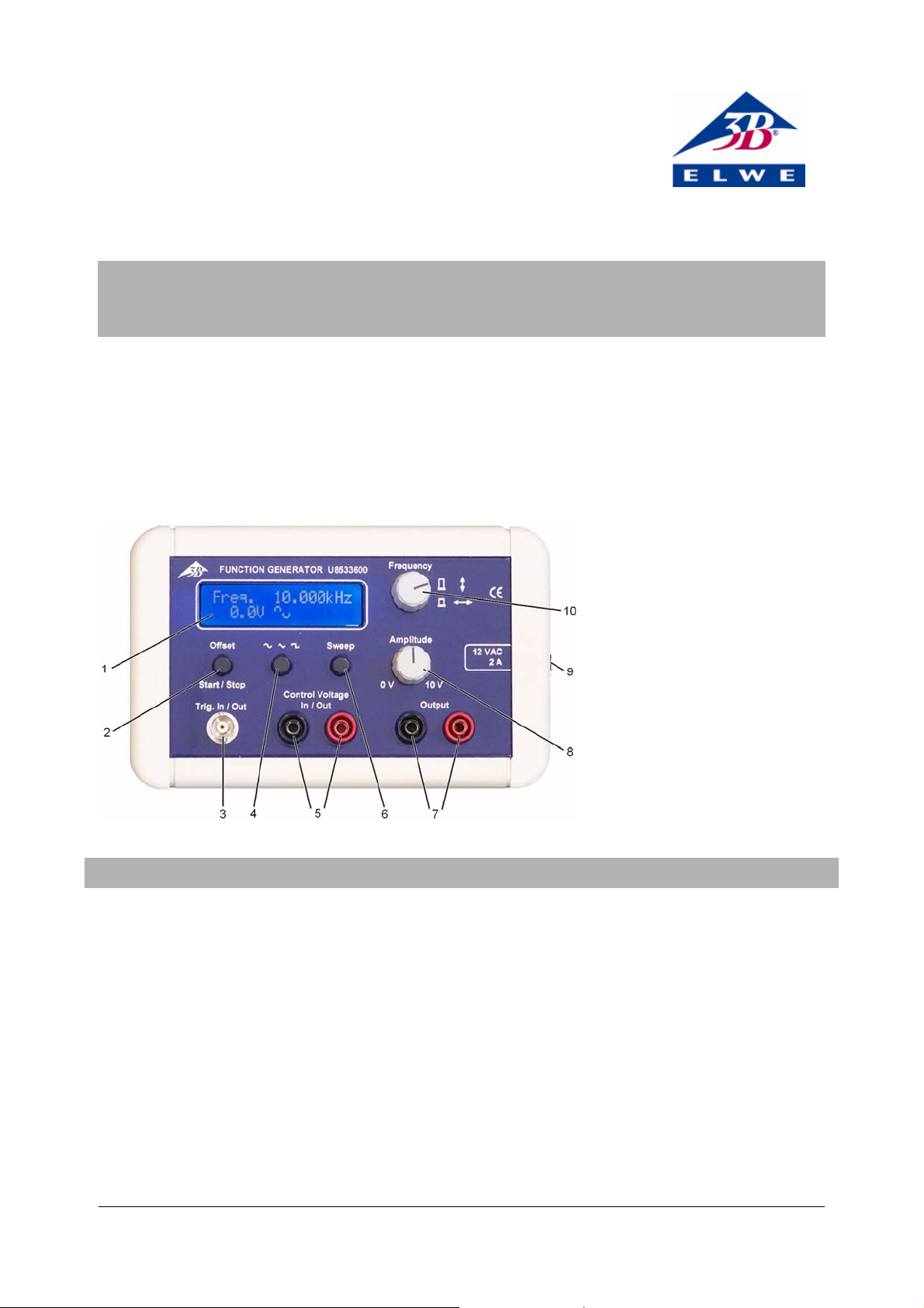
1 Display
2 Offset button and Start/Stop
button for sweep function
3 BNC socket, input/output for
trigger
4 Button for setting waveform
5 Input for control voltage/output
for ramp
6 Button for selecting sweep mode
7 Output sockets
8 Amplitude knob
9 Power socket for plug-in power
supply
10 Frequency knob
The function generator FG100 conforms to safety regulations for electrical measuring, control and laboratory
equipment as specified in DIN EN 61010 Part 1. It is to
be operated in dry rooms as appropriate for the use of
electrical equipment.
Safe operation of this equipment is guaranteed as long as
it is used as stipulated. However, there is no guarantee of
safety if the equipment is used incorrectly or carelessly.
If there is any suspicion that the equipment can no
longer be operated without risk (e.g. if visible damage is
detected), the equipment must immediately be withdrawn from use and secured in such a way as to prevent
its inadvertent operation.
• Only use the instrument in a dry environment.
• Do not attempt to operate the equipment except
with its own power supply.
• Do not apply any external voltage to the output terminals.
• Do not exceed the maximum input voltage of 5 V for
the control voltage and trigger.
Electromagnetic waves can be generated, in particular at
high frequencies or with waveforms featuring a large
amount of harmonics, which may cause interference to
other equipment in the area.
• Ensure that no other equipment is being interfered
with.
• If necessary, only operate the FG100 function gen-
erator for short periods.
• Do not use experiment leads longer than 5 m.
1
Page 2

2. Description
The FG100 function generator features an external
sweep function with a power amplifier for use in student and practical experiments on simple harmonic
oscillation, alternating current and induction.
The equipment outputs sine-wave, triangular wave and
square wave voltages with adjustable amplitude and
frequency. The built-in power amplifier allows it to
handle currents of up to 1 A.
Operating modes for sweep mode:
External mode: the sweep is proportional to the set frequencies and depends directly on an external control voltage of between 0 and 5 V. This allows for frequency modulation using modulation frequencies of up to 200 Hz.
Internal/Continuous: At the start and whenever the
voltage passes through zero a 5-V pulse is output from
the TRIG OUT socket. A voltage of 0 - 5 V directly propor-
tional to the sweep voltage is output from the Control
Voltage socket.
Internal/Single: At the start a 5-V pulse is output from
the TRIG OUT socket. The sweep can also be initiated by
a 5-V pulse to the TRIG IN socket. A voltage of 0 - 5 V
directly proportional to the sweep voltage is output
from the Control Voltage socket. The sweep stops after
one run-through and continues at the starting frequency
until another start pulse is input (using the buttons or
the trigger).
The most recently used sweep-mode settings will be
stored in the function generator for the next time it is
switched on.
The output is protected against shorts circuits, inductive
voltages and spark discharges.
The device is equipped with fold-away feet.
Power is provided via a 12-V AC plug-in power supply.
The FG100 function generator with order number
1009956 is intended for a mains voltage of 115 V (±10%),
whereas the one numbered 1009957 is for 230 V (±10%).
3. Technical data
Signals:
Frequency range: 0.001 Hz to 100 kHz
Distortion factor: <1 %
Signal forms: Sine, square, triangular
Offset: 0 to ±5 V, adjustable in 0.1 V
steps
Output:
Output amplitude: 0 to 10 V, continuously ad-
justable
Power output: 10 W, permanent
Output current: 1 A, 2.0 A max.
Sweep:
Sweep modes: External, continuous internal,
individual internal
Frequency range: 1 Hz to 100 kHz
Stop/start
frequency ratio: Max. 1000:1, e.g. 2 Hz to 2 kHz
max.
Time range: 0.04 s to 1000 s
External sweep: Start via trigger pulse or ap-
plication of 0 to 5 V control
voltage; max. modulation frequency: 200 Hz
Internal sweep: Start and stop via Start/Stop
button; one trigger output per
cycle plus proportional voltage
General data:
Power supply: Plug-in power supply, 12 V AC, 2 A
Dimensions: 170x105x40 mm
3
Weight: 0.5 kg
4. Operation
4.1 Turning on
• Plug the power supply into the mains and connect it
to the function generator.
This immediately turns on the equipment so that it is
ready to use. The top line of the display will indicate the
current frequency while the bottom line shows the DC
offset and the waveform.
4.2 Setting the frequency
• Use the frequency knob to set the desired frequency.
• Push in and turn the knob to select the digit to be
changed on the display and then turn the knob to
set the specific frequency.
The active digit will be indicated on the display by a
flashing underline character.
4.3 Setting the offset
• Press the Offset button to activate offset adjustment.
• Turn the frequency knob to set the required value in
steps of 0.1 V.
Pressing in the frequency knob resets the value back to zero.
• When the desired value has been set, Press Offset again.
4.4 Selecting a waveform
• Press the waveform button until the waveform you
want is indicated on the display.
It is possible to select a sine wave square wave or triangular wave.
2
Page 3

4.5 Sweep
• Press the Sweep button to activate sweep mode.
The initial frequency is shown on the top line of the
display, while the bottom shows the DC offset, the waveform and the word "START".
• Turn the frequency knob to set the desired initial
frequency as described in section 4.2.
• To set the frequency for when the sweep stops, press
the Sweep ´button again.
• The bottom line of the display will show the word
"STOP".
• Turn the frequency knob to set the desired fre-
quency for when the sweep stops.
Pressing the Sweep button again now sets the equipment into sweep mode. The sub-modes External, Inter-
nal Continuous or Internal Single will be indicated on the
top line of the display.
• Turn the frequency knob to select the desired sub-
mode for the sweep function.
• Press Sweep again.
If external mode has been selected, then "EXT" will be
displayed at the bottom right of the display. If internal
mode was display, the word "TIME" will be displayed
there.
• Adjust the sweep time by turning the frequency
knob and press Sweep again.
The start frequency will be shown on the display and the
word "READY" will appear at the bottom right.
• Press Offset/Start/Stop to start the sweep.
While the sweep function is operating, the current frequency will be indicated on the top line of the display,
while the bottom line shows the DC offset, the waveform
and the word "RUN". The sweep can be paused by holding down the Offset/Start/Stop button. Pressing it again
allows the sweep to continue. The word "BREAK" will be
displayed while it is paused.
• To exit sweep mode press Sweep again.
In order to modify the values, it is necessary to exit sweep
mode and initiate the procedure again. It should be
noted that the DC offset cannot be altered by this means.
5. Care and maintenance
• Before cleaning the equipment, disconnect it from
its power supply.
• Use a soft, damp cloth to clean it.
6. Disposal
• The packaging should be disposed of at local recy-
cling points.
• Should you need to dispose of the equipment itself,
never throw it away in normal domestic waste. Local
regulations for the disposal of electrical equipment
will apply.
7. Sample experiments
7.1 Demonstration of standing transverse waves on a
rubber rope and investigating the dependence of
their wavelength on the frequency and the tension
The following equipment is also required to perform the
experiment:
1 Accessories for rope waves 1008540 / U85560081
1 Dynamometer, 5 N 1003106 / U20034
1 Vibration generator 1000701 / U8556001
Experiment leads
• Set up the waves on a string accessory as in its man-
ual.
• Hang the dynamometer on the holder. If necessary,
first calibrate the zero point.
• Connect the function generator to the vibration
generator.
• Attach the rubber rope to the vibration generator,
pass it under the deflection device then upwards,
and hang it on the dynamometer. Ensure that it
runs as parallel as possible to the base plate.
• Apply tension to the rubber rope by moving the
dynamometer.
• On the function generator, select the “sine” wave-form.
• Adjust the frequency until 4 vibration loops are
obtained.
The wavelength is now half the length of the cord.
• Move the dynamometer higher up the rod until the
tension is four times the previous value.
The band now vibrates with just one peak and one trough.
The wavelength is therefore equal to the length of the band.
The following parameters are found to give good results:
Rope length (= distance from vibration generator to
deflection device): 60 cm, Frequency; approx. 44 Hz,
initial cord tension: 0.5 N
Rope length: 70 cm, Frequency; approx. 38 Hz, initial
cord tension: 0.5 N
3
Page 4

7.2 Parallel LC resonant circuit
The following equipment is also required to perform the
experiment:
1 3B NETlog™ (230 V, 50/60 Hz) 1000540 / U11300-230
1 Basic experiment board (230 V, 50/60 Hz)
1000573 / U11380-230
or
1 3B NETlog™ (115 V, 50/60 Hz) 1000539 / U11310-115
1 Basic experiment board (115 V, 50/60 Hz)
1000572 / U11380-115
1 3B NETlab
TM
1000544 / U11310
1 Computer
Experiment leads
• Start the 3B NETlabTM software and open the paral-
lel LC resonant circuit experiment.
• Set up the experiment in accordance with the in-
structions in the experiment template.
• Carry out the experiment.
Fig. 1 Experiment set-up to demonstrate standing transverse waves
Fig. 2 Experiment set-up for parallel LC resonant circuit
Elwe Didactic GmbH • Steinfelsstr. 5 • 08248 Klingenthal • Germany • www.elwedidactic.com
3B Scientific GmbH • Rudorffweg 8 • 21031 Hamburg • Germany • www.3bscientific.com
Subject to technical amendments
© Copyright 2012 3B Scientific GmbH
 Loading...