

3B Scientific Photoelectric Effect Vacuum Cell User Manual
3B SCIENTIFIC® PHYSICS
Vacuum Photocell U8482415
Gas Filled Photocell U8482445
Instruction Sheet
07/09 LT/ALF
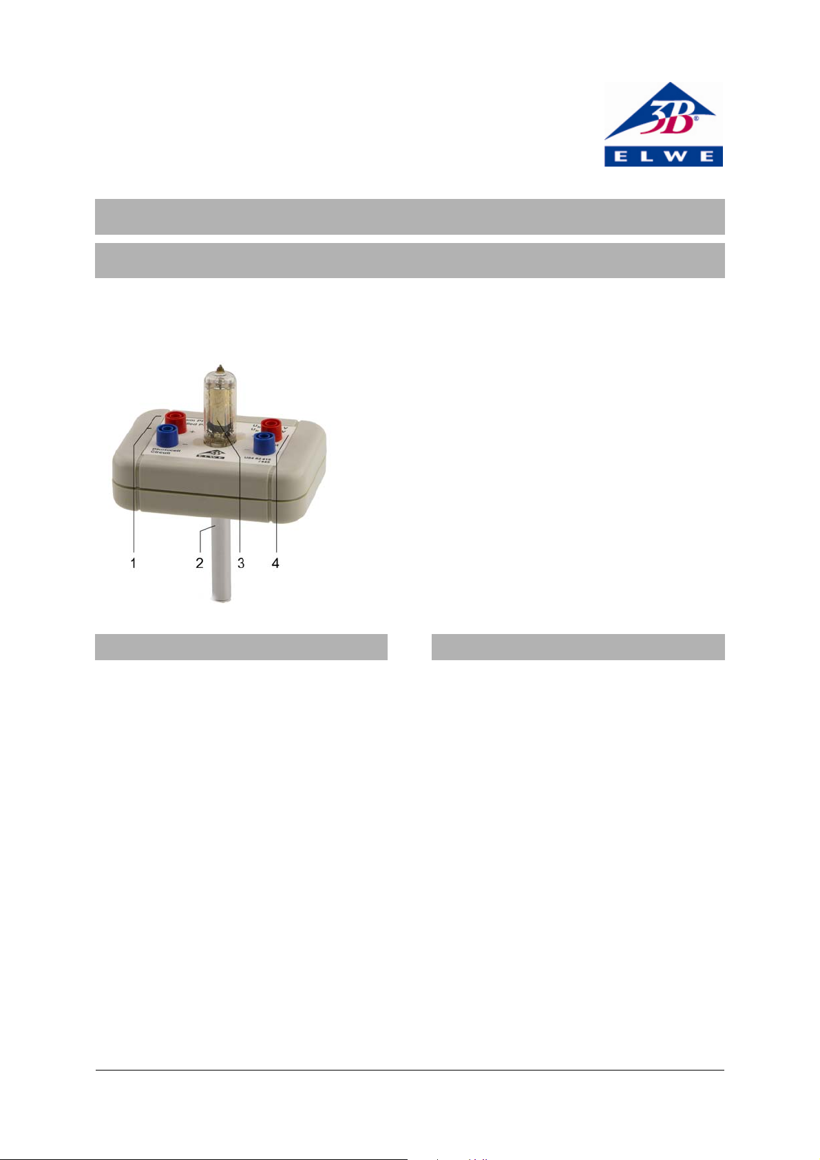
1 Sockets for collector voltage
2 Clamping rod
3 Photocell tube
4 Output sockets
1. Safety instructions
When the instrument is used in accordance with
the instructions and regulations, safe operation is
ensured. However, safety is not guaranteed if the
instrument has been treated inappropriately or
carelessly.
If there is reason to believe that safe operation is
no longer possible (e.g., if there is visible damage),
the instrument must not be used, or if in use it
must be taken out of service immediately.
When the photocell is used with the 500 V DC
power supply (U33000), there may be voltages that
are dangerous to touch in the area of the
connections.
• Only use safety experiment leads for the
connections.
• Only make connections when the voltage
supply is switched off.
• Keep within the specified operating
parameters.
• Do not expose the photocell to temperatures
above 50°C.
• Do not expose the photocell to direct sunlight,
and store it in darkness whenever possible.
2. Description
The vacuum photocell U8482415 and the gas-filled
photocell U8482445 are used for demonstrating
the photoelectric effect and the increase of the
flow of electrons when the light intensity is
increased.
The photocell mounting and the electrical circuit
are protected for safe handling in a plastic housing
with a clamping rod.
The photocell tubes have a base with 7 pins, and
can only be fitted into the housing in the correct
orientation. The light-sensitive side of the photocell
is on the side of the anode filament which is
approximately in the centre of the cathode shell.
Figure 1 shows the circuit of the photocell. The
collector voltage U
is applied to the pair of sockets
b
(1), and produces an electric field between the
cathode and the anode. The dependence of the
photoelectric current on the light intensity can be
measured by connecting a microammeter to the
other pair of sockets (2).
If the measurement is made by connecting a
voltage amplifier, the voltage must be measured
relative to the blue socket (1). As the measurement
1

is made in parallel to the photocell in this case, the
voltage at the amplifier input decreases as the light
intensity is increased.
R2 and C1 provide smoothing of the collector
The experiment demonstrates the linear
dependence of the photoelectric current on the
light intensity.
• Set up the photocell using a stand and clamps
voltage, and R2 also protects the photocell tube.
• With a constant collector voltage U
3. Operation
• Take the photocell tube out of the packaging
and carefully plug it into the base.
• Protect the photocell from direct sunlight!
• Read the value of the photoelectric current on
• Move the light source so that the distance to
4. Sample experiments
Halving the distance has the effect of quadrupling
4.1 Demonstration of the photoelectric effect
For carrying out the experiment, the following
additional equipment is needed:
1 DC power supply, 500 V (230 V, 50/60 Hz)
U33000-230
or
1 DC power supply, 500 V (115 V, 50/60 Hz)
U33000-115
1 Digital multimeter U118091
Light source
Stand and clamps or optical bench
the photoelectric current.
5 Technical data
or an optical bench (Fig. 2).
and in a
b
completely darkened room, place a light
source (an optical lamp or a low-power light
bulb) at a measured distance from the
photocell.
the multimeter.
the photocell is half the previous value and
again read the photoelectric current.
U8482415 U8482445
Type: Valvo 90CV Valvo 90CG
Cathode: Caesium on oxidised silver Caesium on oxidised silver
Effective cathode area: 2.4 cm² 2.4 cm²
Wavelength for max. sensitivity: 850 nm 850 nm
Anode/cathode capacitance CAC:
Collector voltage Ub:
Working resistance Ra:
Dark current Io :
0.6 pF 0.6 pF
50 V, max. 100 V 50 V, max. 90 V
1 MΩ 1 MΩ
0.05 µA 0.1 µA
Sensitivity: 20 µA/lumen 125 µA/lumen
Max. photoelectric current
density
:
Ik
3 µA/cm² 0.7 µA/cm²
Max. ambient temperature: 50° C 50° C
2
 Loading...