

Page 1
3B SCIENTIFIC
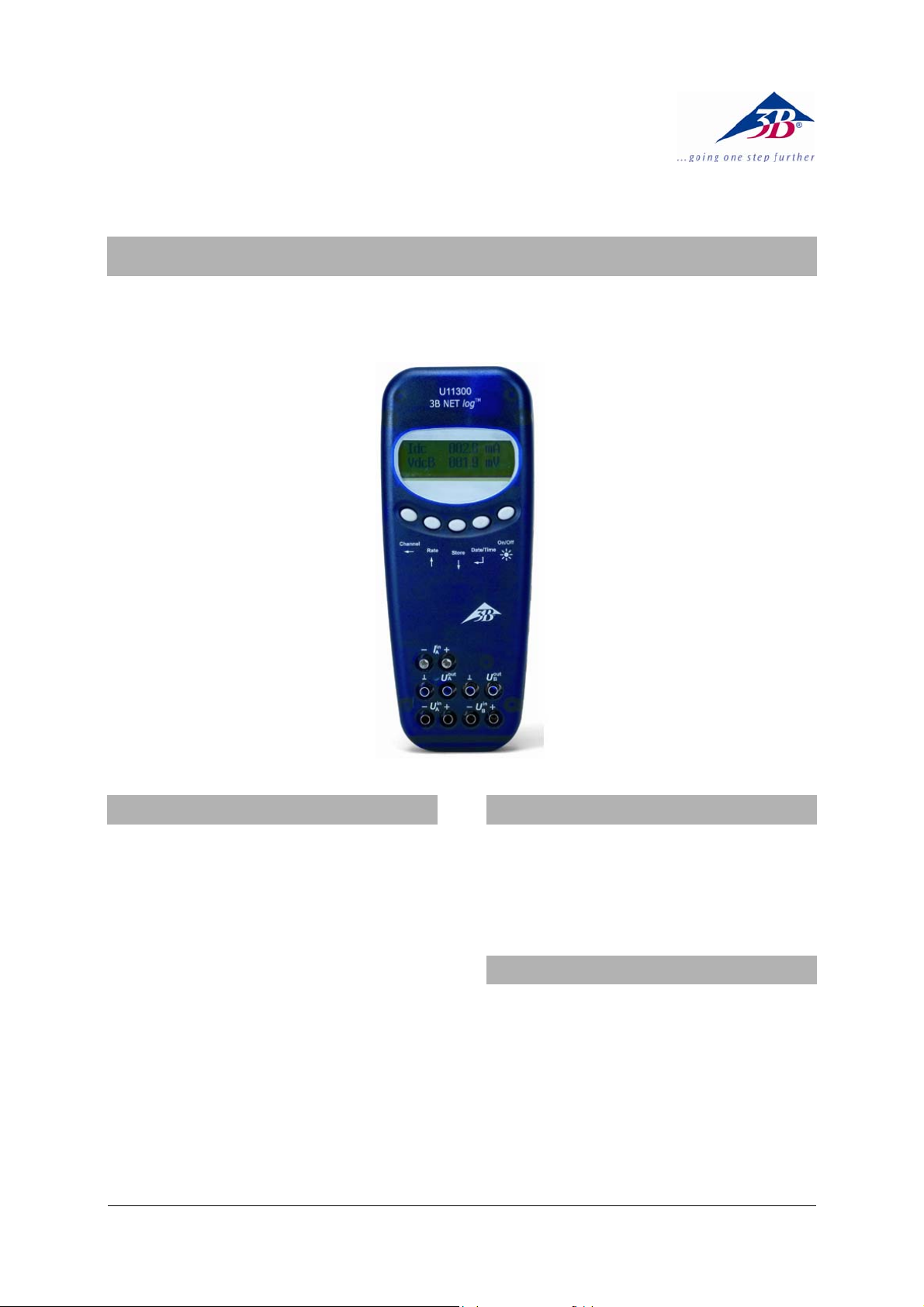
3B Netlog™ mit Ethernet Anschluss U11300ip
Bedienungsanleitung
07/10 MEC
®
PHYSICS
1. Sicherheitshinweise
Der sichere Betrieb des 3B NETlog™ ist gewährleistet, wenn die folgenden Hinweise beachtet werden:
• 3B NETlog™ nicht mit Spannungen über ±20 V
oder Strömen über ±2 A beschalten.
• 3B NETlog™ nicht mit Wasser in Kontakt brin-
gen.
• 3B NETlog™ nicht Temperaturen über 80°C
aussetzen.
Der Betriebsspannungseingang ist verpolungssicher
aber nicht überspannungsfest.
• Keine Spannungen über 4,5 V an den Betriebs-
spannungseingang anlegen.
Beim Betrieb mit dem Ethernetanschluss ist das 3B
NETlog™ immer mit dem Steckernetzgerät zu
betreiben.
2. Lieferumfang
1 3B NETlog™
1 Steckernetzgerät (4,5 V DC, 300mA)
1 USB-Kabel
1 Installations-CD
3. Einführung
3B NETlog™ ist ein multimediales Datenerfassungsund Auswertesystem für Strom- und Spannungsmessungen und Messungen mit Sensoren, das mit
oder ohne Computeranbindung eingesetzt werden
kann. Mit der zugehörigen Software 3B NETlab™
können sowohl Messungen mit frei gewählten
Parametern als auch vorbereitete Experimente
durchgeführt werden. In den vorbereiteten Experimenten wird der Anwender durch eine interaktive
Experimentierumgebung geführt, in der die Messparameter bereits festgelegt wurden. In einem
1
Page 2
Netzwerk können Lehrer und Schüler ihre Messergebnisse wechselseitig verfolgen.
Ohne Computeranbindung ist das 3B NETlog™
einsetzbar als digitales Multimeter für Strom- und
Spannungsmessungen sowie in Verbindung mit
verschiedenen Sensoren als Handmessgerät mit
automatischer Sensorerkennung.
4. Technische Daten
4.4 Digitale Ausgänge
Kanäle 6
Signal: TTL
Anschluss: 8-Pin Mini-DIN-Buchse
4.5 Weitere Daten
Computeranschluss: USB
Interner Datenspeicher: 128 k
Display: 64 x 122 Matrix
4.1 Analoge Eingänge
Spannungseingänge (Kanal A und B):
Spannungsversorgung: 4,5 V DC/300 mA oder 3
Messprinzip: 2 Differenzverstärker
Messbereiche: ±200 mV, ±2 V, ±20 V
Überspannungsschutz: bis ± 40 V
Anschlüsse: 4-mm Sicherheitsbuch-
sen
Abmessungen: 21 cm x 8 cm x 4 cm
Stromeingang (Kanal A):
Masse: 400 g (inklusive Batte-
Messbereiche: ±200 mA, ±2 A
Überstromschutz: bis ±2,5 A
Anschlüsse: 4-mm Sicherheitsbuch-
sen
Sensoreingänge (Kanal A und B):
Sensortyp: analog
5.1 Komponenten
Sensoridentifikation: automatisch
Sensoranschlüsse: 8-Pin Mini-DIN-Buchsen
Triggerung: kontinuierlich
Abtastrate: 50 kSamples/s
Auflösung: 12 bit
4.2 Analoge Ausgänge (Kanal A und B)
Bezugspunkt (Masse): gemeinsam
Messbereich: ± 5 V
Anschlüsse: 4-mm Sicherheitsbuch-
sen und 8-Pin Mini-DIN-
Buchsen
Abtastrate: 10 kSamples/s
Auflösung: 12 bit
4.3 Digitale Eingänge
Kanäle: 4 (aufgeteilt in 2 TTL-
Eingänge, davon ein
schneller Zeiteingang,
und 2 Eingänge über Op-
tokoppler)
Abtastrate: 50 kSamples/s
100 kSamples/s (schnel-
ler Zeiteingang)
Anschluss: 8-Pin Mini-DIN-Buchse
für Messwerte und Einheiten
Batterien (AA, LR6 oder
AM3) wegen deren längerer Nutzungsdauer wird
die Verwendung von Alkaline-Batterien empfohlen.
rien)
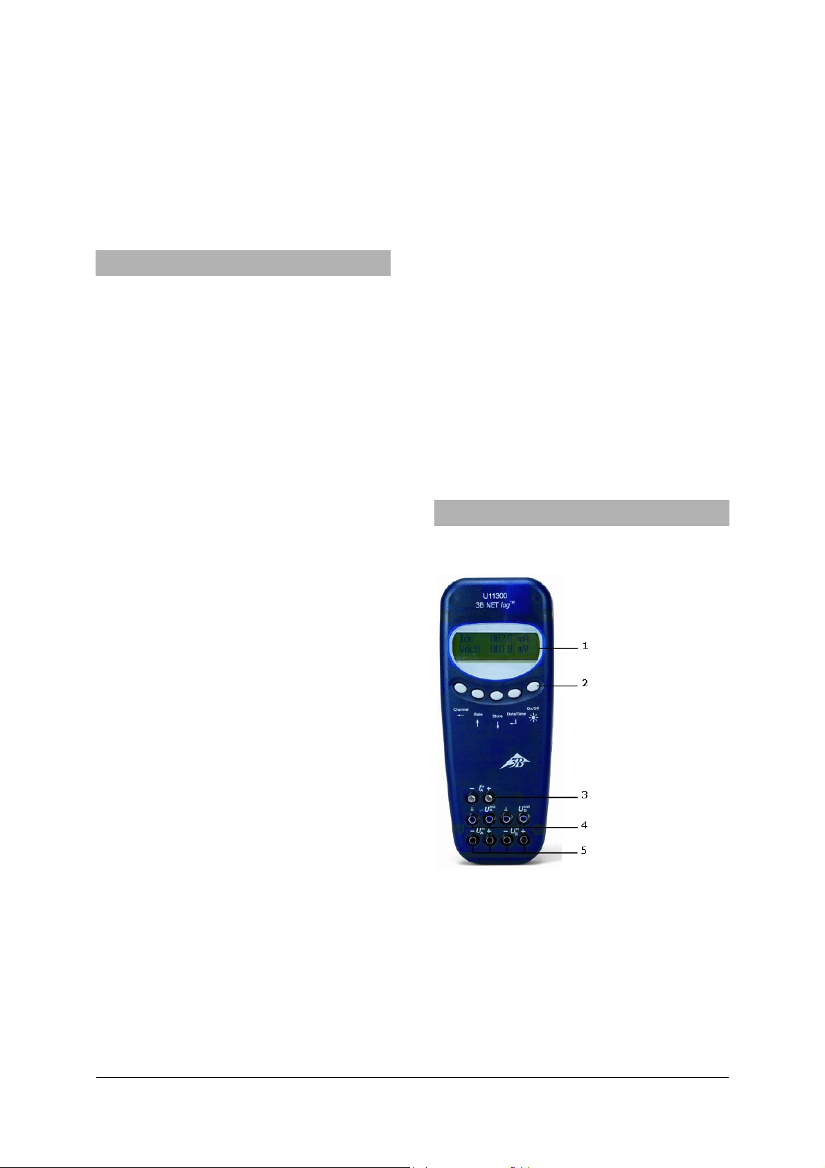
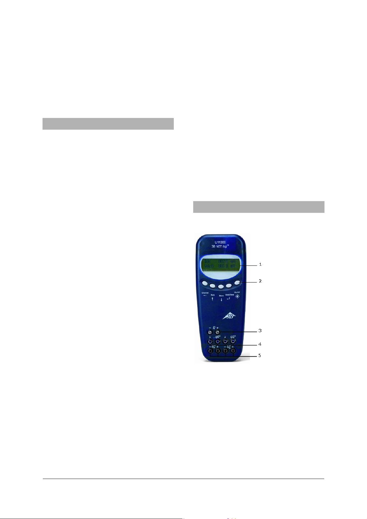
5. Beschreibung
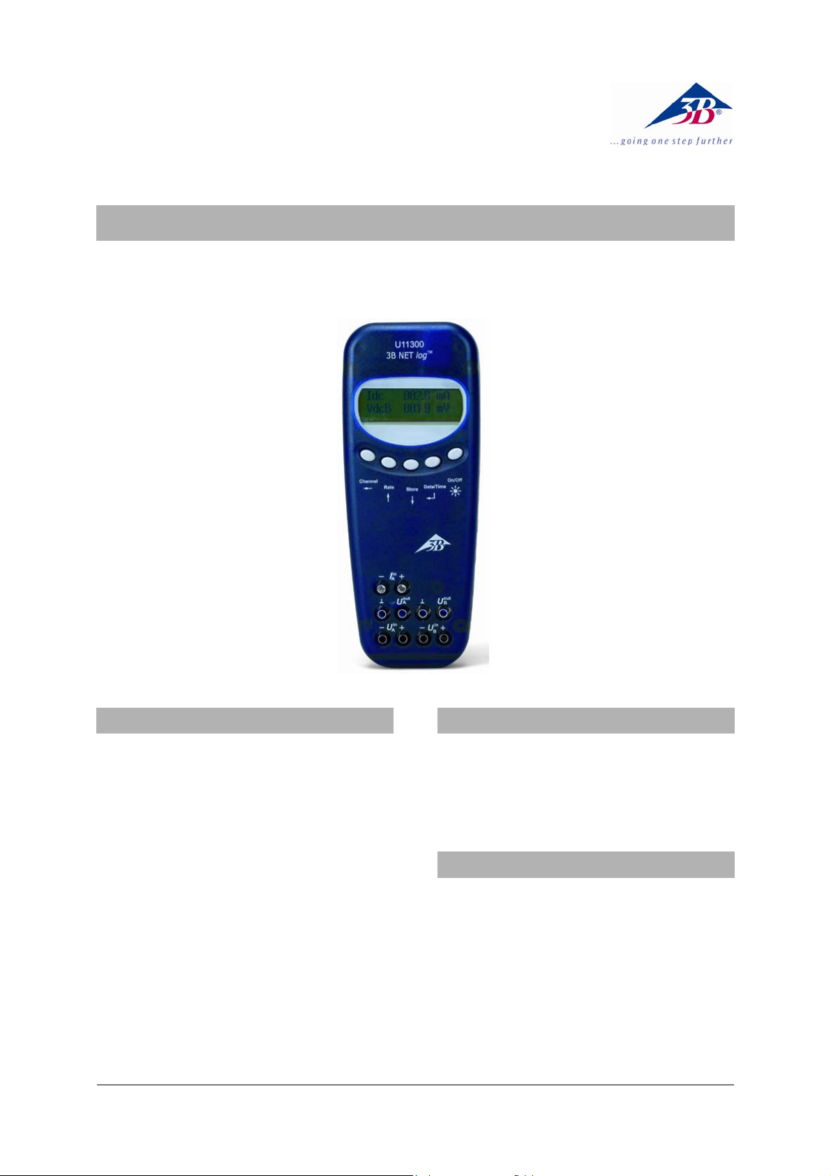
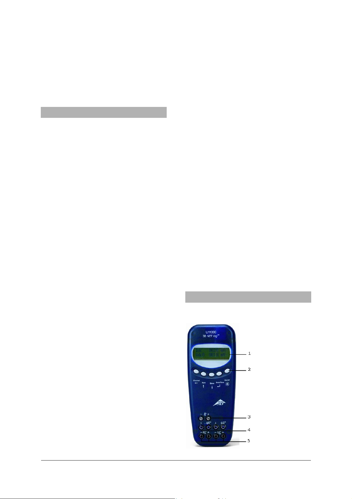
1 Display
2 Bedienfeld
3 Stromeingang für
Kanal A
4 Spannungsausgänge
für Kanal A und B
5 Spannungseingänge
für Kanal A und B
2
Page 3
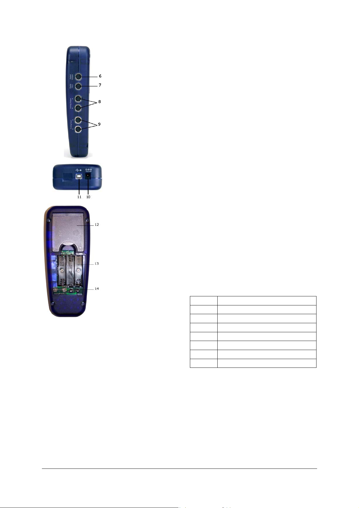
6 Digitale Ausgänge
7 Digitale Eingänge
8 Analoge Ausgänge
A und B
9 Analoge Eingänge
A und B
Taste Date/Time
•
Einschalten der Batterie- und Temperaturan-
↵
zeige.
• Einschalten der Zeitanzeige.
• Einschalten der Datumsanzeige.
• Auswahl der Betriebsart (manuell bzw. auto-
matisch).
• Bestätigung für Display-Anzeige →.
10 Hohlbuchse für
Steckernetzgerät
11 USB-Anschluss
12 Aufsteller
13 Batteriefach
14 Sicherung
5.2 Bedienfeld
Das Bedienfeld des 3B NETlog™ besteht aus fünf
multifunktionalen Tasten für den Betrieb ohne PCAnbindung.
Taste On/Off
• Ein- und Ausschalten des Geräts (zum Ausschal-
ten Taste ca. 2 s gedrückt halten).
• Ein- und Ausschalten der Displaybeleuchtung
(kurzzeitig drücken).
Taste Store
• Aufruf des Dataloggers.
• Scrollen nach unten im Menü.
• Auswahl Yes oder No.
• Bestätigung für Display-Anzeige ↓.
↓
Taste Rate
•
• Scrollen nach oben im Menü.
• Auswahl Yes oder No.
• Bestätigung für Display-Anzeige ↑.
↑
Auswahl der Abtastrate.
Taste Channel
•
Auswahl der Messparameter für Kanal A und B.
• Wechsel zwischen den Feldern bei Zeit- und
←
Datumseinstellung.
• Schritt zurück in der Menüverzweigung.
5.3 Messparameter
Name Bedeutung
VdcA Gleichspannung auf Kanal A
VacA Wechselspannung auf Kanal A
Idc Gleichstrom auf Kanal A
Iac Wechselstrom auf Kanal A
VdcB Gleichspannung auf Kanal B
VacB Wechselspannung auf Kanal B
Bin Binärdarstellung
5.4 Anschluss von Sensoren
Angeschlossene Sensoren werden von
3B NETlog™ automatisch erkannt. Auf dem Display
erscheint die Meldung
PROBE DETECT… . Anschließend werden der Mess-
wert und die zugehörige Maßeinheit des angeschlossenen Sensors auf dem Display angezeigt.
3
Page 4
6. Inbetriebnahme
s
t
6.1 Betrieb mit Steckernetzgerät
• Hohlstecker des Steckernetzgeräts in die Hohl-
buchse des 3B NETlog™ stecken.
• Steckernetzgerät ans Netz anschließen.
• Ggf. Taste On/Off drücken.
6.2 Betrieb mit Batterien
• Deckel des Batteriefachs öffnen und drei Batte-
rien (AA, LR6 oder AM3) unter Beachtung der
Polarität einsetzen (Batterien nicht im Lieferumfang enthalten).
• Ggf. Taste On/Off drücken.
7. Betrieb mit Computer und
Software 3B NETlab™
Zum Betrieb des 3B NETlog™ mit einem Computer
benötigt man die Software 3B NETlab™ und einen
Computer mit folgenden Systemanforderungen:
• Windows 98, 2000, ME, XP
• Intel Pentium III oder ähnlicher Prozessor mit
mindestens 600 MHz, 128 MB RAM und 100 MB
Festplattenspeicher.
• Microsoft Internet Explorer Vers. 6 oder höher
Hinweis: Während des Betriebs mit einem
Computer dürfen die Tasten des Bedienfelde
des 3B NETlog™ grundsätzlich nicht gedrück
werden.
7.1 Treiberinstallation
Vor der Installation der Software 3B NETlab™ ist es
notwendig, den USB-Treiber zu installieren:
• 3B NETlog™ über USB-Kabel mit dem Computer
verbinden.
Der Computer meldet, dass er eine neue Hardware
gefunden hat. Danach öffnet sich das Fenster des
Hardware-Assistenten:
• Installations-CD ins CD-Rom-Fach des Compu-
ters einlegen.
Windows 2000:
• „Nach einem passenden Treiber für das Gerät
suchen“ auswählen.
• Unter Suche nach Treiberdateien „CD-Rom-
Laufwerke“ auswählen. (Falls kein Treiber gefunden wird, „Andere Quellen angeben“ auswählen).
Windows XP:
• Kein Windows Update herstellen.
• „Software von bestimmter Quelle installieren“
auswählen.
• Unter „Durchsuchen“ die Quelle des Treibers
auf der CD angeben.
• Bei der Hardwaremeldung, dass die Software
den Windows-Logo-Test nicht bestanden hat,
auf „Installation fortsetzen“ drücken.
Alternativ kann der Ordner mit der Treiberdatei zu
Beginn von der CD auf den Computer kopiert und
von dort installiert werden.
Ausnahme:
Falls bereits die Software zu den Produkten U21800 CCD-Linear-Kamera und/oder U21830
Spektrophotometer auf dem Computer installiert
ist, bitte folgende Anweisungen ausführen.
• 3B NETlog™ über USB-Kabel mit dem Computer
verbinden.
Der Computer meldet nicht, dass er eine neue
Hardware gefunden hat.
• Installations-CD ins CD-Rom-Fach des Compu-
ters einlegen.
Windows 2000:
• Systemsteuerung -> System -> Hardware ->
Geräte-Manager öffnen.
• Doppelklicken auf USB-Contoller.
• Doppelklicken auf „ULICE USB Product“.
• Auf Treiber -> Treiber aktualisieren klicken.
(Assistent zum Aktualisieren von Gerätetreibern
startet).
• „Alle bekannten Treiber für das Gerät in einer
Liste anzeigen und entsprechenden Treiber
selbst auswählen“ wählen.
• Auf „Datenträger“ und anschließend auf
„Durchsuchen“ klicken und den Pfad des Treiber auswählen.
• Die Frage, ob die Datei überschrieben werden
soll, mit „Ja“ bestätigen.
Windows XP:
• Systemsteuerung -> System -> Hardware ->
Geräte-Manager öffnen.
• Doppelklicken auf USB-Contoller.
• Doppelklicken auf „ULICE USB Product“.
• Auf Treiber -> Aktualisieren klicken. klicken.
(Hardware Assistent startet)
• Kein Windows Update herstellen.
4
Page 5
• „Software von bestimmter Quelle installieren“
j
auswählen.
• „Nicht suchen, sondern zu installierenden
Treiber selbst wählen“ auswählen.
• Auf „Datenträger“ und anschließend auf
„Durchsuchen“ klicken und den Pfad des Treiber auswählen.
• Die Frage, ob die Datei überschrieben werden
soll, mit „Ja“ bestätigen.
• Bei der Hardwaremeldung, dass die Software
den Windows-Logo-Test nicht bestanden hat,
auf „Installation fortsetzen“ drücken.
7.2 Softwareinstallation
Hinweise zur Installation der Software 3B NETlab™
entnehmen Sie bitte der Installationsanleitung für
diese Software.
8. Betrieb ohne Computer
Die Bedienung des 3B NETlog™ beim Betrieb ohne
Computer erfolgt über die Tasten des Bedienfeldes,
deren Funktion sich je nach Bedienungszustand
ändert.
Hinweis: Mit der Taste Channel
←
kann
ederzeit ein Menüaufruf rückgängig ge-
macht werden.
8.1 Anzeige des Batteriestands und der Temperatur
• 3B NETlog™ mit der Taste On/Off einschalten.
• Taste Date/Time ↵ drücken.
Auf dem Display erscheint
z.B.: BATTERY: 100 %
TEMP.: 22.0 °C
8.2 Einstellung der Uhrzeit
• 3B NETlog™ mit der Taste On/Off einschalten.
• Taste Date/Time ↵ zweimal drücken (das Zeit-
feld erscheint auf dem Display).
• Taste Store ↓ drücken (das Eingabefeld SET
TIME erscheint auf dem Display).
• Im Eingabefeld mit den Tasten Rate ↑ oder
↓ den gewünschten Wert eingeben und
Store
mit der Taste Channel
← zwischen dem Stun-
den-, Minuten- und Sekundenfeld wechseln.
• Zur Bestätigung Taste Date/Time ↵ drücken.
8.3 Einstellung des Datums
• 3B NETlog™ mit der Taste On/Off einschalten.
• Taste Date/Time ↵ dreimal drücken (das Da-
tumsfeld erscheint auf dem Display).
• Taste Store ↓ drücken (das Eingabefeld SET
DATE erscheint auf dem Display).
• Im Eingabefeld mit den Tasten Rate ↑ oder
Store ↓ den gewünschten Wert eingeben und
mit der Taste Channel ← zwischen dem Jah-
res-, Monats- und Tagesfeld wechseln.
• Zur Bestätigung Taste Date/Time ↵ drüc-
ken.
8.4 Einsatz als Handmessgerät für Strom und
Spannung
• 3B NETlog™ in Betrieb nehmen.
• Spannungs- bzw. Stromeingang des gewünsch-
ten Kanals A oder B beschalten.
• Einen eventuell im gleichen Kanal angeschlos-
senen Sensor entfernen.
Zur Einstellung und Auswahl der Messparameter:
• Taste Channel ← drücken (Menüfeld DISPLAY
SIGNAL 1 erscheint auf dem Display).
• Mit den Tasten Rate ↑ oder Store ↓ den ge-
wünschten Messparameter auswählen.
• Betriebsart mit Taste Date/Time ↵ auswählen
(Menüfeld RANGE SIGNAL 1 erscheint auf dem
Display).
• Mit den Tasten Rate ↑ oder Store ↓ die ge-
wünschte Betriebsart auswählen.
• Mit Taste Date/Time ↵ diese Auswahl bestäti-
gen (Menüfeld DISPLAY SIGNAL 2 erscheint auf
dem Display).
• Mit den Tasten Rate ↑ oder Store ↓ den ge-
wünschten Messparameter auswählen.
• Mit den Tasten Rate ↑ oder Store ↓ die ge-
wünschte Betriebsart auswählen.
• Auswahl mit Taste Date/Time ↵ bestätigen (bei
manueller Betriebsart erscheint ein Punkt vor
dem jeweiligen Messparameter).
3B NETlog™ ist messbereit.
8.5 Einsatz als Handmessgerät mit Sensoren
• 3B NETlog™ in Betrieb nehmen.
• Sensor an geeigneten Eingang anschließen und
Beschaltungen der 4-mm-Buchsen des gleichen
Kanals entfernen.
Nach Abschluss der automatischen Sensorerkennung PROBE DETECT… ist 3B NETlog™ messbereit.
8.6 Einstellung der Abtastrate
• Taste Rate drücken (das Auswahlfeld SAMPLE
RATE erscheint).
• Mit den Tasten Rate ↑ oder Store ↓ die ge-
wünschte Abtastrate auswählen.
• Taste Date/Time ↵ drücken (es erscheinen
nacheinander die Annahmefelder STORE ANA-
5
Page 6
LOG INPUT 1, STORE ANALOG INPUT 2 und
STORE BINARY INPUTS).
• In jedem Annahmefeld YES oder NO mit den
Tasten Rate ↑ oder Store ↓ auswählen und mit
der Taste Date/Time ↵ bestätigen (nach der
Bestätigung erscheint das nächste Annahmefeld).
8.7 Datalogger
Im Dataloggermodus erfasst 3B NETlog™ die Daten
mit einer vorgewählten Abtastrate und speichert
sie intern ab. Nach Abschluss einer Messung können die Daten an einen Computer zur Auswertung
übertragen werden.
Dataloggermodus aufrufen:
• Taste Store ↓ drücken (es erscheint das Anzei-
gefeld STORE mit der Anzeige → START
bzw. ↑ CLEAR → START).
Datalogger starten:
Bei der Anzeige → START:
• Mit der Taste Date/Time ↵ die Aufzeichnung
der Daten starten (im Anzeigefeld erscheint die
Anzeige „BUSY → STOP“ und die Messung be-
ginnt).
Datalogger stoppen:
Bei der Anzeige → STOP:
• Mit der Taste Date/Time ↵ die Aufzeichnung
der Daten stoppen (im Anzeigefeld erscheint
die Anzeige ↑ CLEAR → START)
Datalogger löschen:
Bei der Anzeige ↑ CLEAR:
• Taste Rate ↑ drücken (im Anzeigefeld erscheint
die Anzeige MEM.CLEAR? → YES).
• Zur Bestätigung die Taste Date/Time ↵ drü-
cken.
Dataloggermodus beenden:
Bei der Anzeige ↑ CLEAR → START:
• Taste Channel ← drücken.
9. Betrieb mit dem Ethernetanschluss
Wenn das 3B NETlog™ mit dem Ethernetanschluss
betrieben wird, ist darauf zu achten, dass es mit
dem Steckernetzgerät betrieben wird.
Bei Betrieb außerhalb des eigenen LAN Bereichs
besteht die Gefahr einer Sicherheitslücke, dass
andere Teilnehmer ihre Daten sehen können. Daher ist der Betrieb des Ethernetanschlusses außerhalb des eigenen LAN Bereichs auf eigene Gefahr
zu verwenden.
10. Software IP-finder
Wird das 3B NETlog™ mit dem Ethernetanschluss
betrieben, muss zuerst der Anwender feststellen, in
welchem Nummernkreis seine IP Adresse liegt.
10.1 Zuweisen der IP-Adresse
• 3B NETlog™ mit dem Ethernetkabel vebinden.
• 3B NETlog™ Gerät einschalten.
• Software NETBoxCfg.exe starten.
• Radiobutton "YES" bei DHCP anwählen.
• Auf "Apply" drücken.
• MAC und IP Adressen werden im linken Fenster
angezeigt.
10.2 Eintragen der IP-Adresse in 3BNETlab™
• 3BNETlab™ starten.
• Im Messlabor einen neuen Datensatz anlegen.
• Nachdem sich das Fenster mit dem neuen
Datensatz geöffnet hat, auf den Button rechts
neben Geräteanschluss klicken.
• In das sich öffnende Eingabelfeld die ermittelte
IP-Adresse eingetragen.
11. Übertragungssoftware 3B NETdata
In 3B NETlog™ gespeicherte Daten können mit der
Software 3B NETdata ausgelesen und in Textdateien gespeichert werden. Außerdem bietet die Software die Möglichkeit, die Messmodi und parameter des 3B NETlog™ einzustellen.
Hinweis:
Beim Betrieb mit der Software 3B NETdata
darf immer nur ein 3B NETlog™ am Computer angeschlossen sein.
11.1 Treiberinstallation
Vor der Installation der Software 3B NETdata ist es
notwendig, den USB-Treiber zu installieren. Hierzu
wie in 7.1 beschrieben verfahren.
11.2 Softwareinstallation
• Installationsprogramm „Setup_3BNETdata.exe“
ausführen und den Anweisungen auf dem Bildschirm folgen.
11.3 Bedienelemente
Die Bedienungsoberfläche besteht aus drei Karteikarten, die über den zugehörigen Reiter in den
Vordergrund geholt werden kann. Die Karteikarte
„Daten auslesen“ dient zur Übertragung der Messdaten aus dem Speicher des 3B NETlog™, die Karteikarte „Gerät einstellen“ zur Einstellung der
6
Page 7

Messparameter und Messmodi des 3B NETlog™ und
die Karteikarte „Firmware-Update“ zur Aktualisierung der Firmware des 3B NETlog™, siehe hierzu
Beschreibung in Kapitel 10.
Daten auslesen
• Auslesen: Liest alle im Gerätespeicher vorhan-
denen Daten und zeigt eine Übersicht über die
Messungen in einer Liste an.
• Abbrechen: Bricht den Lesevorgang ab.
• Status: Zeigt den aktuellen Status an.
• Zeit: Zeigt die seit Beginn des Lesevorgangs
verstrichene Zeit an.
• Verbl. Zeit: Zeigt eine Schätzung für die Rest-
dauer des Lesevorgangs an.
• Vestr. Zeit : Abgelaufene Zeit in Sekunden,
von Beginn des Lesevorgangs.
• Optionen: Hier können folgende Einstellungen
vorgenommen werden:
• Dezimaltrennzeichen: Legt das Dezimaltrenn-
zeichen fest, das in exportierten Dateien verwendet wird.
• Datums-/Zeitformat: Legt das Datums- und
Zeitformat fest, das in exportierten Messdateien verwendet wird.
• Liste links: Zeigt die ausgelesenen Dateien an.
• Liste rechts: Zusätzliche Auswahl an Spalten,
welche zu den exportierten Dateien hinzugefügt werden.
• Index: Fortlaufende Nummer beginnend mit
1.
• Absolute(s) Datum/Zeit: Datum und Uhrzeit,
an dem der Messwert / der Messdatensatz aufgenommen wurde.
• Relative Zeit [s]: Abgelaufene Zeit in Sekun-
den, von Beginn der Messung bis zur Aufnahme des aktuellen Messwertes / Messdatensatzes.
• Ausgewählte Daten speichern: Schreibt die in
der linken Liste ausgewählten Messdaten in
Textdateien (Tab-getrennt). Für jede Messung
wird ein Dateiname abgefragt. Die voreingestellten Dateinamen enthalten Datum, Uhrzeit,
Messgrößen und Abtastrate und können alternativ ohne Änderung übernommen werden.
• Beenden: Beendet das Programm.
Gerät einstellen
• Vdc/Vac/(Idc/Iac): Wählt den Messmodus für
den oben angegebenen Analogeingang. (Vdc:
Gleichspannung / Vac: Wechselspannung / Idc:
Gleichstrom / Iac: Wechselstrom).
• Schieberegler (200mV – 20V / 200mA – 2A):
Wählt den Messbereich für den oben angegebenen Analogeingang.
• Automatisch: Wenn dieses Kontrollkästchen
aktiviert ist, wird der Messbereich vom Gerät
während der Messung automatisch angepasst.
• Aufzeichnen: Legt fest, ob über den oben
angegebenen Eingang Daten aufgezeichnet
werden sollen.
• Abtastrate: Hier kann die Abtastrate für die
Messungen eingestellt werden. Im Feld f= wird
die Frequenz und im Feld T= die zugehörige
Periodendauer anzeigt.
• Einstellungen übertragen: Überträgt die ge-
wählten Einstellungen auf das Gerät.
• Gerätespeicher löschen: Löscht den gesamten
Gerätespeicher.
• Beenden: Beendet das Programm.
11.4 Auslesen und Speichern von Messdaten
Auslesen und Speichern von gemessenen Daten mit
dem 3B NETlog™:
• 3B NETlog™ über den USB-Anschluss mit dem
Computer verbinden.
• 3BNETdata starten und Reiter „Daten ausle-
sen“ anklicken.
• Auslesen drücken und warten, bis der Fort-
schrittsbalken durchgelaufen ist.
• In der linken Liste die zu speichernden Mes-
sungen auswählen.
• In der rechten Liste Spalten, die zusätzlich mit
aufgeführt werden sollen auswählen.
• Auf Ausgewählte Daten speichern drücken.
• Für jede Messung einen Dateinamen angeben
oder vorgeschlagenen Namen annehmen.
• Zur Weiterverarbeitung der gespeicherten
Dateien Tabellenkalkulations- oder Datenanalyseprogramme verwenden.
12. Firmware-Update
• In der Software 3B NETdata den Reiter Firmwa-
re-Update anklicken.
• Die Anweisungen im linken Feld der Software
befolgen und abschließend die Schalfläche
„Start“ drücken.
Die aktuelle Version der Firmware wird nun automatisch installiert. Alternativ kann mit der Schaltfläche „Durchsuchen“ nach älteren Firmwaredateien gesucht und diese installiert werden.
7
Page 8
13. Format der exportierten Dateien
Die exportierten Dateien haben folgendes Format (in <> stehende Angaben sind Platzhalter für Daten. Je nach
Auswahl fallen Spalten weg):
# <Datum> <Zeit>, <Eingänge/Messmodi>, <Abtastrate>, <Anzahl der Messdatensätze>
Index (tab) Absolute(s) Datum/Zeit (tab) Relative Zeit (tab) <Messgröße von Analogeingang A>[<Einheit von
Analogeingang A>] (tab) <Messgröße von Analogeingang B>[<Einheit von Analogeingang B>] (tab) Dig A (tab)
Dig B (tab) Dig C (tab) Dig D(return)
1(tab)<Absolute(s) Datum/Zeit des ersten Messdatensatzes>(tab)<Relative Zeit des ersten Messdatensatzes>(tab)<Wert 1 Analogeingang A>(tab)<Wert 1 von Analogeingang B>(tab)<Wert 1 von Digitaleingang
C>(tab)<Wert 1 von Digitaleingang D>(return)
2(tab)<Absolute(s) Datum/Zeit des zweiten Messdatensatzes>(tab)<Relative Zeit des zweiten Messdatensatzes>(tab)<Wert 2 Analogeingang A>(tab)<Wert 2 von Analogeingang B>(tab)<Wert 2 von Digitaleingang
C>(tab)<Wert 2 von Digitaleingang D>(return)
u.s.w.
14. Fehler und mögliche Ursachenbehandlung
16. CE-Zeichen
Fehler Ursache Behandlung
3B NETlog™
lässt sich im
Batterien sind
zu schwach.
Batteriebetrieb nicht
einschalten.
Beim Drücken auf den
Button „Test“
in der Software
3B NETlab™
erscheint
nicht die
3B NETlog™ ist
nicht einge-
schaltet.
Verbindung
zwischen Com-
puter und 3B
NETlog™ be-
steht nicht.
Meldung
„Verbindung
Neue Batterien
einlegen oder
das Steckernetzgerät verwenden.
3B NETlog™ einschalten.
Verbindung zwischen Computer
und 3B NETlog™
überprüfen.
„Test“ erneut
drücken und
ggf. mit Taste F5
aktualisieren.
besteht!“
15. Support
Für weitere Fragen und Hinweise können Sie gerne
unseren Support-Dienst in Anspruch nehmen:
Email: support@3bnetlog.com
Internet: http://www.3bnetlog.com/
3B NETlog™ erfüllt die Anforderungen der EURichtlinien
• EN 61010-1: typgeprüft
• EN 61326-1: auf Störfestigkeit und Störaus-
strahlung geprüft
Die Konformität wird durch das CE-Zeichen auf
dem Gerät bestätigt.
17. Lizenz
3B Netlog™ und 3B Netlab™ sind eingetragene
Marken der 3B Scientific GmbH in Deutschland und
in anderen Ländern.
Das Computerprogramm 3B Netlab™ ist weltweit
urheberrechtlich geschützt. Es darf nur für schulische Zwecke in Schulen und Institutionen verwendet werden, inklusive häuslicher Vorbereitung.
Herstellung von Kopien, unbefugte Verwendung
oder unbefugter Vertrieb sind nicht erlaubt.
3B Scientific GmbH • Rudorffweg 8 • 21031 Hamburg • Deutschland • www.3bscientific.com
Technische Änderungen vorbehalten
© Copyright 2010 3B Scientific GmbH
Page 9

3B SCIENTIFIC
3B Netlog™ with Ethernet port U11300ip
Instruction manual
06/10 MEC
®
PHYSICS
1. Safety instructions
To guarantee the safe functioning of the
3B NETlog™ equipment, it is necessary to abide by
the following instructions:
• Do not connect the 3B NETlog™ device to a
voltage in excess of ±20V or current in excess
of ±2A.
• Make sure the 3B NETlog™ device does not
come into contact with water.
• The 3B NETlog™ device should not be exposed
to temperatures above 80°C.
The operating voltage input is protected against
polarity reversal. However, it is not protected
against excess voltage.
• Do not apply voltage in excess of 4.5V to the
operating voltage input.
When the Ethernet port is used, the 3B NETlog™
unit must always be powered via its mains power
supply.
2. Scope of delivery
1 3B NETlog™ device
1 Power supply unit (4.5V DC, 300mA)
1 USB cable
1 Installation CD
3. Introduction
3B NETlog™ is a multimedia data acquisition and
evaluation system for current and voltage measurements and for measurements using sensors. The
system can be used with or without being connected to a computer. With the accompanying
3B NETlab™ software, measurements can be conducted with arbitrarily chosen parameters as well
as in prepared experiments. The prepared experiments take the user through an interactive experimental environment where the measurement parameters have already been defined. When used
1
Page 10
within a network, the teacher and students can
mutually monitor their results.
Without being connected to a computer, the
3B NETlog™ device can be used as a digital multimeter for current and voltage measurements.
Combined with different sensors, the 3B NETlog™
equipment can also be used as a handheld unit
with automatic sensor recognition.
4. Technical specifications
4.1 Analog inputs
Voltage inputs (channels A and B):
Measuring equipment: 2 Differential amplifiers
Measuring range: ±200mV, ±2V, ±20V
Surge voltage protection: Max. ±40V
Connections: 4-mm safety sockets
Current input (channel A):
Measuring range: ±200mA, ±2A
Excess current protection: Max. ±2.5A
Connections: 4-mm safety sockets
Sensor inputs (channels A and B):
Sensor type: Analog
Sensor identification: Automatic
Sensor connections: 8-pin mini DIN sockets
Sampling: Continuous
Sampling rate: 50k samples/s
Resolution: 12 bit
4.2 Analog outputs (channels A and B)
Reference point (earth): Common
Measuring range: ± 5V
Connections: 4-mm safety sockets and
8-pin mini DIN sockets
Sampling rate: 10kSamples/s
Resolution: 12bit
4.3 Digital inputs
Channels: 4 (separated into 2 TTL
inputs, one of which is a
high-speed time input,
plus 2 inputs via optocoupler)
Sampling rate: 50k samples/s
100k samples/s (highspeed time input)
Connection: 8-pin mini DIN socket
4.4 Digital outputs
Channels: 6
Signal: TTL
Connection: 8-pin mini DIN socket
4.5 Additional data
Computer connection: USB
Internal data memory: 128k
Display: 64 x 122 matrix for
measurements and units
Power supply: 4.5V DC/300mA or 3
batteries (AA, LR6 or
AM3); owing to their
longer battery life, use of
alkaline batteries is rec-
ommended.
Dimensions: 21cm x 8cm x 4cm
Weight: 400g (including batteries)
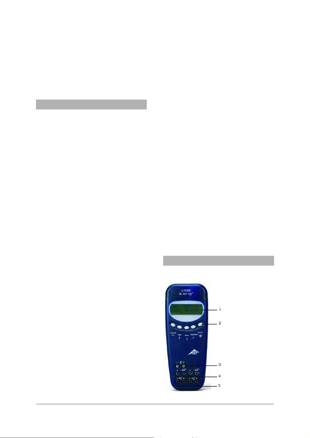
5. Description
5.1 Components
1 Display
2 Operating controls
3 Current input for
channel A
4 Voltage outputs for
channels A and B
5 Voltage inputs for
channels A and B
2
Page 11

6 Digital outputs
7 Digital inputs
8 Analog outputs
A and B
9 Analog inputs
A and B
10 Recessed socket for
power supply unit
11 USB connection
12 Mount
13 Battery compartment
14 Fuse
5.2 Operating controls
The operating controls of the 3B NETlog™ unit
consist of five multi-function buttons for operation
without connection to a PC.
On/Off button
• Switching the device on and off (keep the but-
ton pressed for approx. 2 seconds to switch off
the device)
• Switching the display lighting on and off
(briefly press the button)
Date/Time button ↵
• Switching on the battery and temperature
displays
• Switching on the time display
• Switching on the date display
• Selection of operating mode (manual or auto-
matic)
• Confirming the display →
Store button ↓
• Communication to data logger
• Scrolling down the menu
• Selecting Yes or No
• Confirming the display ↓
Rate button ↑
• Selection of sampling rate
• Scrolling up within the menu
• Selecting Yes or No
• Confirming the display ↑
Channel button ←
• Selection of measurement parameters for
channels A and B
• Changing between fields while setting the time
and date
• Return to previous menu
5.3 Measurement parameters
Name Significance
VdcA DC voltage on channel A
VacA AC voltage on channel A
Idc DC current on channel A
Iac AC current on channel A
VdcB DC voltage on channel B
VacB AC voltage on channel B
Bin Binary representation
5.4 Connection of sensors
Connected sensors are automatically detected by
the 3B NETlog™ device. The following status message appears on the display:
PROBE DETECT…. Subsequently, the measurement
and the unit corresponding to the connected sensor are displayed.
3
Page 12
6. Commissioning
r
6.1 Operating with the power supply unit
• Insert the recessed plug of the power supply
unit into the recessed socket of the 3B NETlog™
device.
• Connect the power supply unit to the mains.
• If necessary, press the On/Off button.
6.2 Operating with batteries
• Open the lid of the battery compartment and
insert three batteries (AA, LR6 or AM3) while
carefully observing the polarity (batteries not
included).
• If necessary, press the On/Off button.
7. Operating with a computer and 3B NETlab™
software
In order to operate the 3B NETlog™ equipment
with a computer, the 3B NETlab™ software and a
computer with the following system requirements
are necessary:
• Windows 98, 2000, ME, XP
• Intel Pentium III or similar processor with min.
600MHz, 128MB RAM and 100MB hard disc
storage
• Microsoft Internet Explorer Version 6 or higher
Note when operating via a computer, neve
press the buttons on the 3B NETlogTM console.
7.1 Driver installation
Before installing the 3B NETlab™ software, it is
important to install the USB driver:
• Connect 3B NETlog™ to the computer via the
USB cable.
The computer reports that it has detected a new
hardware. Subsequently, the window of the hardware wizard opens:
• Insert the installation CD into the CD-ROM
drive of the computer.
Windows 2000:
• Select “Search for the best driver for your de-
vice”.
• Under search for driver files, select “CD-ROM
drives”. (If no driver can be found, select “Display other source locations”.)
Windows XP:
• Do not activate Windows Update.
• Select “Install software from specified loca-
tion”.
• Under “Browse”, specify the location of the
driver on the CD.
• A hardware message will state that the soft-
ware has failed to pass the Windows Logo Test.
You should nevertheless click “Proceed with installation”.
As an alternative, the folder containing the driver
file can be copied directly onto the computer from
the CD and can be installed from the hard disk.
Exception:
If the software for the U21800 CCD linear
camera and/or U21830 Spectrophotometer products has already been installed onto the computer,
follow the instructions below:
• Connect 3B NETlog™ to the computer via the
USB cable.
The computer will not report that a new hardware
has been detected.
• Insert the installation CD into the CD-ROM
drive of the computer.
Windows 2000:
• System control panel -> System -> Hardware ->
open Device manager.
• Double-click USB controller.
• Double-click “ULICE USB Product”.
• Click Driver -> Update driver. (The wizard for
updating the device driver will start.)
• Select “Show all known drivers from list and
search for the suitable/appropriate driver”.
• Select “Drive” and then “Search” to establish
the path to the driver.
• Click “Yes” to confirm that the file should be
overwritten.
Windows XP:
• System control panel -> System -> Hardware ->
open Device manager.
• Double-click on USB controller.
• Double-click “ULICE USB Product”.
• Click Driver -> Update driver. (The hardware
assistant will start.)
• Do not activate Windows Update.
• Select “Install software from specific source”.
4
Page 13
• Select “Do not search. Autodetect driver”.
t
e
• Select “Drive” and then “Search” to establish
the path to the driver.
• Click “Yes” to confirm that the file should be
overwritten.
• Click “Proceed with installation” when the
hardware message states that the software has
failed to pass the Windows Logo Test.
7.2 Software installation
Note on installing the software
For this software, please refer to the installation
instructions available in the 3B NETlab™ software
manual.
8. Operating without a computer
Operating a 3B NETlog™ device without a computer
is achieved by using the buttons on the operating
panel. The functions of these buttons may change
according to the operation being undertaken.
Note: a menu selection can be cancelled a
any time by using th
Channel ← button.
8.1 Battery level and temperature display
• Switch on the 3B NETlog™ device by pressing
the On/Off button.
• Press the Date/Time ↵ button.
The following should appear on the display:
e.g.: BATTERY: 100%
TEMP.: 22.0°C
8.2 Setting the time
• Switch on the 3B NETlog™ device by pressing
the On/Off button.
• Press the Date/Time ↵ button twice (the time
field will appear on the display).
• Press the Store ↓ button (the input field for SET
TIME will appear on the display).
• Specify the desired time in the input field by
pressing the Rate ↑ or the Store ↓ button and
use the Channel ← button to skip between the
hours, minutes and seconds fields.
• Confirm by pressing the Date/Time ↵ button.
8.3 Setting the date
• Switch on the 3B NETlog™ device by pressing
the On/Off button.
• Press Date/Time ↵ button three times (the date
field will appear on the display).
• Press the Store ↓ button (the input field for SET
DATE will appear on the display).
• Specify the desired date in the input field by
pressing the Rate ↑ or the Store ↓ button and
use the Channel ← button to skip between the
year, month and day fields.
• Confirm by pressing the Date/Time ↵ button.
8.4 Application as a handheld device for meas-
uring current and voltage
• Set up the 3B NETlog™ equipment.
• Connect the voltage/current input of channel A
or B, as desired.
• If necessary, disconnect any sensor which
might be connected to the same channel.
Setting and selecting measurement parameters:
• Press the Channel ← button (the menu DIS-
PLAY SIGNAL 1 will appear on the display).
• Select the desired measurement parameter
with the Rate ↑ or the Store ↓ button.
• Select the mode of operation with the
Date/Time ↵ button (the menu RANGE SIGNAL
1 will appear on the display).
• Select the desired mode of operation with the
Rate ↑ or the Store ↓ button.
• Confirm this selection with the Date/Time ↵
button (the menu DISPLAY SIGNAL 2 will appear on the display).
• Select the desired measurement parameter
with the Rate ↑ or the Store ↓ button.
• Select the desired mode of operation with the
Rate ↑ or the Store ↓ button.
• Confirm the selection with the Date/Time ↵
button (a dot will appear in front of the respective measurement parameter when operating
manually).
The 3B NETlog™ device is ready to conduct measurements.
8.5 Application as a handheld measuring device
with sensors
• Set up the 3B NETlog™ equipment.
• Connect the sensor to the relevant input and
remove the connections of the 4-mm sockets
from the same channel.
After the automatic sensor detection PROBE DETECT… has been completed, the 3B NETlog™
equipment is ready to conduct measurements.
5
Page 14

8.6 Setting the sampling rate
y
g
• Press the Rate ↑ button (the options list for
SAMPLE RATE will appear).
• Select the desired sampling rate with the
Rate ↑ or the Store ↓ button.
• Press the Date/Time ↵ button (the settings
STORE ANALOG INPUT 1, STORE ANALOG INPUT
2 and STORE BINARY INPUTS will appear in
succession).
• Select YES or NO for each setting with the
Rate ↑ or the Store ↓ button and confirm with
the Date/Time ↵ button (the subsequent set-
ting will appear after each confirmation).
8.7 Data logger
In data logger mode, the 3B NETlog™ equipment
records the data with a pre-selected sampling rate
and saves it internally. After completing a measurement, the data can be transferred onto a computer for evaluation.
Calling up data logger mode:
• Press the Store ↓ button (STORE will appear
with → START or ↑ CLEAR → START displayed).
Starting data logger:
When the display shows → START:
• Start recording data with the Date/Time ↵
button (“BUSY → STOP” will appear in the display and the measurement begins).
Stopping the data logger:
When the display shows → STOP:
• Stop recording data by pressing the
Date/Time ↵ button (↑ CLEAR → START will
appear in the display).
Clearing data logger:
When the display shows ↑ CLEAR:
• Press the Rate ↑ button (MEM.CLEAR? → YES
will appear in the display).
• Confirm by pressing the Date/Time ↵ button.
Exiting data logger mode:
When the display shows ↑ CLEAR → START:
• Press the Channel ← button.
9. Operation via Ethernet port
When the Ethernet port is used, care should be
taken to ensure the 3B NETlog™ unit is powered via
its mains power supply.
When used outside your own internal LAN, there
may be a security risk whereby other users might
be able to view your data. Therefore, you only use
the Ethernet port outside your own LAN at your
own risk.
10. IP finder software
If the 3B NETlog™ device is connected via its
Ethernet port, the user will first need to establish
the range of numbers used for the IP address.
10.1 Assigning an IP address
• Connect up the 3B NETlog™ unit via an
Ethernet cable.
• Turn on the 3B NETlog™ equipment.
• Run the NETBoxCfg.exe software.
• Select the "YES" radio button for DHCP.
• Click "Apply".
• MAC and IP addresses will be displayed in a
window on the left.
10.2 Entering an IP address in 3BNETlab™
• Run 3BNETlab™.
• Open a new record in the measurement lab.
• Having opened the window with the new data
record, click the button on the right next to
Device port.
• Enter the IP address already determined in the
entry box that opens.
11. 3B NETdata transfer software
Data stored in the 3B NETlog™ memory can be
retrieved and saved as text files with the help of
the 3B NETdata software. In addition, the software
also provides the capability to set modes of measurement and measurement parameters.
Note: Only one interface 3B NETlog™ ma
be connected to the computer when usin
the software 3B NETdata.
11.1 Installation of the driver
Before installing the 3B NETlab™ software it is
necessary to install a USB driver. Proceed as described in 7.1.
6
Page 15

11.2 Software installation
• Run the “Setup_3BNETdata.exe” installation
program and follow the instructions on the
monitor.
11.3 Control elements
The control interface consists of three dialogs that
can be brought to the front by clicking the relevant
tab. The “Read Data” tab is used for transferring
measurement data from the 3B NETlog™ memory,
the “Device Set-up” tab is used for setting the
measurement parameters and mode of measurement for the 3B NETlog™ device and the “Update
firmware” tab is for updating the firmware of
3B NETlog™, see description in chapter 10.
Read Data
• Read: reads all data available in the memory
of the device and presents an overview of the
measurements in a list.
• Abort: aborts the reading operation.
• Status: displays the current status.
• Time elapsed: shows the time that has
elapsed since the beginning of the read operation.
• Time remaining: shows the approximate time
remaining for the read operation.
• Options: the following settings can be made
here:
• Decimal separator: sets the decimal separator
which is used in exported files.
• Date/Time format: specifies the time and date
format which is used in exported measurement files.
• List (left): shows the acquired data.
• List (right): additional selection of columns
which can be added to the exported files.
• Index: serial number, beginning with 1.
• Absolute date/time: date and time when the
measurement/set of measurements was recorded.
• Relative time [s]: elapsed time in seconds,
from the beginning of the measurement to the
recording of the current measurement/set of
measurements.
• Save selected data to files: converts the
measurements selected in the left-hand list
into text files (separated by tab characters). A
file name is requested for each measurement.
The preset file names include date, time,
measurement values and sampling rate and
can be adopted without any changes.
• Quit exits the program.
Device Set-up
• Vdc/Vac/(Idc/Iac): selects the measuring mode for
the aforementioned analog input (Vdc: DC voltage/Vac: AC voltage/Idc: DC current/Iac: AC current).
• Range slider (200mV-20V/200mA-2A): selects
the measurement range for the abovementioned analog input.
• Auto Range: if this control box is activated,
the measuring range is automatically adjusted
by the device during the measurement.
• Store: determines whether data from the
aforementioned input should be stored.
• Sampling rate slider: this sets the sampling
rate for the measurements. Frequency is displayed in the field f=, and the corresponding
cycle duration is displayed in the field T=.
• Apply settings: writes the selected settings to
the device.
• Clear memory: clears the entire memory of
the instrument.
• Quit: exits the program.
11.4 Reading and saving measurement data
Reading and saving measured data with the
3B NETlog™ equipment:
• Connect the 3B NETlog™ equipment to a com-
puter via USB cable.
• Start 3BNETdata and click on the tab “Read Data”.
• Press Read and wait till the progress bar
reaches 100%.
• Select the measurements you wish to be saved
from the list on the left.
• Select columns that are to be written next to
the data.
• Click Save selected data to files
• Enter a file name for each measurement, or
accept the default name.
• For further processing of the saved data, use
spreadsheet or data analysis programs.
12. Update Firmware
• In the 3B NETdata software, click “Update
firmware” tab.
• Follow the instructions in the left-hand section
of the software window and click “Start” in the
options box.
The current version of the firmware will now be
installed automatically. As an alternative, use
“Browse” in the options’ box to search and install
older firmware versions.
7
Page 16
13. Format of exported files
Exported files have the following format (the words shown here between the delimiters <> are simply placeholders for actual data. Entries are separated by tab characters. Depending on the settings, some columns may
be omitted):
# <Date> <Time>, <Inputs/Measurement modes>, <Sampling rate>, <Number of measurement records>
Index (tab) Absolute date/time (tab) Relative time (tab) <Quantity at analog input A>[<Unit for analog input A>]
(tab) <Quantity at analog input B>[<Unit for analog input B>] (tab) Dig A (tab) Dig B (tab) Dig C (tab) Dig
D(return)
1(tab)<Absolute date/time of the first measurement record>(tab)<Relative time of the first measurement record>(tab)<Value 1 of analog input A>(tab)<Value 1 of analog input B>(tab)<Value 1 of digital input
C>(tab)<Value 1 of digital input D>(return)
2(tab)<Absolute(s) Date/Time of the second measurement data set >(tab)<Relative time of the second measurement data set>(tab)<Value 2 of analog input A>(tab)<Value 2 of analog input B>(tab)<Value 2 of digital
input C>(tab)<Value 2 of digital input D>(return)
etc.
14. Faults and possible remedies
16. The CE marking
Fault Cause Remedy
The 3B NETlog™ device
cannot be
switched on
The batteries
are worn out.
Replace with
new batteries or
use the power
supply unit.
when operating with batteries
When the
“Test” button
in the
3B NETlab™
software is
activated, the
“Connected”
message does
not appear.
The 3B NETlog™ device is
not switched
on.
There is no
connection
between the
computer and
the
3B NETlog™
equipment.
Switch on the
3B NETlog™ de-
vice.
Check the con-
nection between
the computer
and 3B NETlog™
device. Press
“Test” again
and, if neces-
sary, refresh by
pressing F5.
15. Support
If you have any queries and/or suggestions, please
feel free to contact our support team:
Email: support@3bnetlog.com
Internet: http://www.3bnetlog.com/
3B NETlog™ conforms to the requirements of these
EU specifications
• EN 61010-1: Protoype-tested
• EN 61326-1: Tested for noise immunity and
interference
Conformity with EU guidelines is indicated by the
CE marking on the device.
17. Licence
3B Netlog™ and 3B Netlab™ are registered trademarks of 3B Scientific GmbH in Germany and other
countries.
The 3B Netlab™ computer program is protected by
worldwide copyright. It may be used exclusively for
educational purposes in schools and educational
institutions, including preparatory purposes at
home. The fabrication of copies, unauthorised
application or unauthorised sale is strictly prohibited.
3B Scientific GmbH • Rudorffweg 8 • 21031 Hamburg • Germany • www.3bscientific.com
Subject to technical amendments
© Copyright 2010 3B Scientific GmbH
Page 17
3B SCIENTIFIC® PHYSICS
3B Netlog™ avec connexion Éthernet U11300ip
Instructions d'utilisation
06/10 MEC
1. Consignes de sécurité
Vous garantissez un fonctionnement fiable du 3B
NETlog™ en respectant les consignes suivantes :
• Ne mettez pas le 3B NETlog™ en circuit avec
des tensions supérieures à ±20 V ou des
courants de plus de ±2 A.
• Ne mettez pas le 3B NETlog™ en contact avec
de l'eau.
• N'exposez pas le 3B NETlog™ à des
températures supérieures à 80 °C.
L'entrée de la tension de service est protégée
contre les inversions de polarité, mais ne résiste
pas aux surtensions.
• N'appliquez pas des tensions supérieures à 4,5
V à l'entrée de la tension de service.
Utilisé avec une connexion éthernet, 3B NETlog™
doit toujours être utilisé avec le bloc secteur.
2. Matériel fourni
1 3B NETlog™
1 alimentation à fiche (4,5 V CC, 300 mA)
1 câble USB
1 CD d'installation
3. Introduction
3B NETlog™ est un système multimédia de saisie et
d'évaluation de données permettant de mesurer le
courant et la tension et d'effectuer des mesures
avec des capteurs, avec ou sans utilisation d'un
ordinateur. Le logiciel permet de réaliser tant des
mesures avec des valeurs paramétrables que des
expériences préparées. Au cours des expériences
préparées, l'utilisateur est guidé par un
environnement interactif dont les paramètres de
mesure sont déjà définis. Reliés en réseau,
1
Page 18
l'enseignant et l'élève peuvent suivre
mutuellement le résultat de leurs mesures.
Sans ordinateur, le 3B NETlog™ peut être utilisé
comme multimètre numérique pour la mesure du
courant et de la tension et, en corrélation avec
différents capteurs, comme appareil de mesure
manuel à détection automatique des capteurs.
4. Caractéristiques techniques
4.1 Entrées analogiques
Entrées de tension (canaux A et B) :
Principe de mesure : 2 amplificateurs
différentiels
Gammes de mesure : ± 200 mV, ± 2 V, ± 20 V
Protection
contre la surtension : jusqu'à ± 40 V
Connexions : douilles de sécurité de
4 mm
Entrée de courant (canal A) :
Gammes de mesure : ± 200 mA, ± 2 A
Protection
contre le surcourant : max. ± 2,5 A
Connexions : douilles de sécurité de 4
mm
Entrées de capteurs (canaux A et B) :
Type de capteur : analogique
Identification
des capteurs : automatique
Conn. des capteurs : mini-douilles DIN à 8
broches
Déclenchement : continu
Vitesse
d'échantillonnage : 50 kSamples/s
Résolution : 12 bits
4.2 Sorties analogiques (canaux A et B)
Point de référence
(masse) : commun
Plage de mesure : ± 5 V
Connexions : douilles de sécurité 4
mm et mini-douilles DIN
à 8 broches
Vitesse
d'échantillonnage : 10 kSamples/s
Résolution : 12 bits
4.3 Entrées numériques
Canaux : 4 (répartis en 2 entrée
TTL, dont 1 entrée de
temps rapide,
et 2 entrées par
optocoupleur)
Vit. d'échantillonnage : 50 kSamples/s
100 kSamples/s (entrée
de temps rapide)
Connexion : mini-douille DIN à 8
broches
4.4 Sorties numériques
Canaux 6
Signal : TTL
Connexion : mini-douille DIN à 8
broches
4.5 Autres caractéristiques
Connexion au PC : USB
Mémoire interne : 128 k
Affichage : 64 x 122 matriciel
pour valeurs de mesures
et unités
Alimentation tension : 4,5 V CC/300 mA ou 3
piles (AA, LR6 ou AM3) des piles alcalines sont
recommandées en raison
de leur plus grande
autonomie
Dimensions : 21 cm x 8 cm x 4 cm
Masse : 400 g (avec piles)
5. Description
5.1 Composants
1 Affichage
2 Champ de commande
3 Entrée de courant pour
canal A
4 Sorties de tension pour
canaux A et B
5 Entrées de tension
pour canaux A et B
2
Page 19

6 Sorties numériques
7 Entrées numériques
8 Sorties analogiques
A et B
9 Entrées analogiques
A et B
10 Douille creuse pour
alimentation à fiche
11 Connexion USB
12 Support
13 Compartiment à piles
14 Fusible
5.2 Champ de commande
Le champ de commande de 3B NETlog™ comprend
cinq touches multifonctionnelles permettant un
emploi sans PC.
Touche On/Off
• Allume et éteint l'appareil (pour l'éteindre,
pressez la touche environ 2 s).
• Allume et éteint l'éclairage de l'affichage
(pressez brièvement).
Touche Date/Time
• Allume la signalisation de la pile et de la
↵
température.
• Allume l'affichage de l'heure.
• Allume l'affichage de la date.
• Sélectionne le mode de service (manuel ou
automatique).
• Confirme l'affichage à l'écran →.
↓
Touche Store
• Appelle l'enregistreur de données
• Défile le menu vers le bas.
• Sélectionne Yes ou No.
• Confirme l'affichage à l'écran ↓.
Touche Rate
• Sélectionne la vitesse d'échantillonnage.
• Défile le menu vers le haut.
• Sélectionne Yes ou No.
• Confirme l'affichage à l'écran ↑•
Touche Channel
• Sélectionne les paramètres de mesure pour les
↑
←
canaux A et B.
• Commute entre les champs lors du réglage de
l'heure et de la date.
• Retourne au niveau précédent dans le menu.
5.3 Paramètres de mesure
Nom Signification
VdcA Tension continue sur le canal A
VacA Tension alternative sur le canal A
Idc Courant continu sur le canal A
Iac Courant alternatif sur le canal A
VdcB Tension continue sur le canal B
VacB Tension alternative sur le canal B
Bin Représentation binaire
5.4 Connexion de capteurs
Les capteurs connectés sont reconnus
automatiquement par 3B NETlog™. L'écran affiche
PROBE DETECT… . Puis la valeur de mesure et
l'unité correspondante du capteur connecté
s'affichent à l'écran.
6. Mise en service
6.1 Alimentation à fiche
• Introduisez la fiche de l'alimentation dans la
douille creuse de 3B NETlog™.
• Branchez l'alimentation au secteur.
• Le cas échéant, pressez la touche On/Off.
6.2 Emploi avec des piles
• Ouvrez le volet du compartiment à piles et
introduisez trois piles (AA, LR6 ou AM3) en
3
Page 20

respectant la polarité (les piles ne sont pas
e
fournies).
• Le cas échéant, pressez la touche On/Off.
7. Utilisation avec ordinateur et logiciel
3B NETlab™
Si vous souhaitez utiliser 3B NETlog™ avec un
ordinateur, vous avez besoin du logiciel
3B NETlab™ et d'un ordinateur répondant aux
exigences suivantes :
• Windows 98, 2000, ME, XP
• Processeur Intel Pentium III ou équivalent d'au
moins 600 MHz, RAM 128 Mo RAM et espace
disque 100 Mo
• Microsoft Internet Explorer version 6 ou
supérieure
Remarque: pendant l'utilisation avec un
ordinateur, il est interdit de presser les
touches du champ de commande d
3B NETlog™.
7.1 Installation du pilote
Avant d'installer le logiciel 3B NETlab™, vous devez
installer d'abord le pilote USB :
• Reliez 3B NETlog™ à l'ordinateur via le câble
USB.
L'ordinateur avertit qu'il a trouvé un nouveau
périphérique. Puis il ouvre la fenêtre de l'assistant
de matériels.
• Insérez le CD d'installation dans le lecteur CD
de l'ordinateur.
Windows 2000 :
• Sélectionnez « Rechercher un pilote approprié
pour mon périphérique ».
• Dans la fenêtre « Recherche de fichiers de
pilote », sélectionnez « Lecteur de CD-ROM » (si
aucun pilote n'est trouvé, sélectionnez
« Emplacement spécifié »).
Windows XP :
• Ne pas mettre à jour Windows.
• Sélectionnez « Installer à partir d'un
emplacement spécifié ».
• Sous « Parcourir », indiquez la source du pilote
sur le CD.
• Lorsque le système affiche le message que le
logiciel n'a pas réussi le test du logo Windows,
cliquez sur « Continuer ».
Autre méthode : copiez vers l'ordinateur le dossier
contenant le fichier du pilote du CD, puis installezle depuis l'ordinateur.
Exception :
Si le logiciel pour les produits U21800
Caméra linéaire CCD et/ou U21830
Spectrophotomètre est déjà installé sur
l'ordinateur, suivez les instructions ci-après.
• Reliez 3B NETlog™ à l'ordinateur via le câble
USB.
L'ordinateur n'avertit pas qu'il a trouvé un
nouveau périphérique.
• Insérez le CD d'installation dans le lecteur CD
de l'ordinateur.
Windows 2000 :
• Ouvrir Panneau de configuration -> Système ->
Matériel -> Gestionnaire de périphériques.
• Double-cliquez sur Contrôleur USB.
• Double-cliquez sur « ULICE USB Product ».
• Cliquez sur Pilotes -> Mettre à jour le pilote
(l'assistant de mise à jour des pilotes démarre).
• Sélectionnez « Installer à partir d'une liste ou
d'un emplacement spécifié ».
• Cliquez sur « Support de données » puis sur
« Parcourir » et sélectionnez le répertoire du
pilote.
• Lorsque le système vous demande d'écraser le
fichier, répondez par « Oui ».
Windows XP :
• Ouvrir Panneau de configuration -> Système ->
Matériel -> Gestionnaire de périphériques.
• Double-cliquez sur Contrôleur USB.
• Double-cliquez sur « ULICE USB Product ».
• Cliquez sur Pilotes -> Mettre à jour le pilote
(l'assistant de matériel démarre).
• Ne pas mettre à jour Windows.
• Sélectionnez « Installer le logiciel depuis un
emplacement spécifié ».
• Sélectionnez « Ne pas rechercher. Je vais
choisir le pilote à installer ».
• Cliquez sur « Disque fourni » puis sur
« Parcourir » et sélectionnez le répertoire du
pilote.
• Lorsque le système vous demande d'écraser le
fichier, répondez par « Oui ».
Lorsque le système affiche le message que le
logiciel n'a pas réussi le test du logo Windows,
cliquez sur « Continuer ».
4
Page 21

7.2 Installation du logiciel
t
L'installation du logiciel 3B NETlab™ est décrite
dans le manuel d'instructions de ce logiciel.
8. Utilisation sans ordinateur
Si 3B NETlog™ n'est pas relié à un ordinateur, vous
vous servirez des touches du champ de commande,
dont la fonction se modifie selon l'état de
commande.
Remarque: la touche Channel
←
perme
d'annuler à tout moment l'appel d'un
menu.
8.1 Affichage de l'état des piles et de la
température
• Allumez 3B NETlog™ avec la touche On/Off.
• Pressez la touche Date/Time ↵.
L'écran affiche
par ex. : BATTERY: 100 %
TEMP.: 22.0 °C
8.2 Réglage de l'heure
• Allumez 3B NETlog™ avec la touche On/Off.
• Pressez deux fois la touche Date/Time ↵ (le
champ de l'heure s'affiche à l'écran).
• Pressez la touche Store ↓ (le champ de saisie
SET TIME s'affiche à l'écran).
• Dans le champ de saisie, entrez la valeur
souhaitée avec la touche Rate ↑ ou Store ↓
dans les champs indiquant l'heure, les minutes
et les secondes en vous déplaçant avec la
touche Channel ←.
• Confirmez votre entrée en pressant la touche
Date/Time ↵.
8.3 Réglage de la date
• Allumez 3B NETlog™ avec la touche On/Off.
• Pressez trois fois la touche Date/Time ↵ (le
champ de la date s'affiche à l'écran).
• Pressez la touche Store ↓ (le champ de saisie
SET DATE s'affiche à l'écran).
• Dans le champ de saisie, entrez la valeur
souhaitée avec la touche Rate ↑ ou Store ↓
dans les champs indiquant l'année, le mois et
le jour en vous déplaçant avec la touche
Channel ←.
• Confirmez votre entrée en pressant la touche
Date/Time ↵.
8.4 Emploi comme appareil de mesure manuel
pour le courant et la tension
• Mettez 3B NETlog™ en service.
• Activez l'entrée de tension ou de courant du
canal A ou B de votre choix.
• Retirez éventuellement le capteur branché au
même canal.
Régler et sélectionner les paramètres de mesure :
• Pressez la touche Channel ← (le champ de
menu DISPLAY SIGNAL 1 s'affiche à l'écran).
• Sélectionnez le paramètre de mesure de votre
choix avec la touche Rate ↑ ou Store ↓.
• Sélectionnez le mode de service avec la touche
Date/Time ↵ (le champ RANGE SIGNAL 1
s'affiche à l'écran).
• Sélectionnez le mode de service de votre choix
avec la touche Rate ↑ ou Store ↓.
• Confirmez votre sélection avec la touche
Date/Time ↵ (le champ DISPLAY SIGNAL 2
s'affiche à l'écran).
• Sélectionnez le paramètre de mesure de votre
choix avec la touche Rate ↑ ou Store ↓.
• Sélectionnez le mode de service de votre choix
avec la touche Rate ↑ ou Store ↓.
• Confirmez votre sélection avec la touche
Date/Time ↵ (en mode manuel, un point
apparaît devant le paramètre de mesure).
3B NETlog™ est prêt à la mesure.
8.5 Emploi comme appareil de mesure manuel
avec des capteurs
• Mettez 3B NETlog™ en service.
• Branchez le capteur à une entrée appropriée et
retirez les connexions des douilles de 4 mm du
même canal.
Lorsque l'affichage PROBE DETECT… signale que le
capteur a été reconnu automatiquement, 3B
NETlog™ est prêt à la mesure.
8.6 Réglage de la vitesse d'échantillonnage
• Pressez la touche Rate (le champ de sélection
SAMPLE RATE s'affiche).
• Sélectionnez la vitesse d'échantillonnage de
votre choix avec la touche Rate ↑ ou Store ↓.
• Pressez la touche Date/Time ↵ (l'écran affiche
successivement les champs STORE ANALOG
INPUT 1, STORE ANALOG INPUT 2 et STORE
BINARY INPUTS).
• Dans chaque champ, sélectionnez YES ou NO
avec la touche Rate ↑ ou Store ↓ et confirmez
avec la touche Date/Time ↵ (après chaque
confirmation, le champ suivant s'affiche).
5
Page 22

8.7 Enregistreur de données
e
e
En mode enregistreur, 3B NETlog™ saisit les
données selon une vitesse d'échantillonnage
prédéfinie, puis les mémorise. Une mesure étant
conclue, ses données peuvent être transmises à un
ordinateur aux fins d'évaluation.
Appeler le mode enregistreur :
• Pressez la touche Store ↓ (le champ STORE
apparaît à l'écran avec l'affichage → START ou
↑ CLEAR → START).
Démarrer l'enregistreur :
Lorsque l'écran affiche → START:
• Démarrez l'enregistrement des données en
pressant la touche Date/Time ↵ (le champ
d'affichage indique BUSY → STOP et la mesure
commence).
Arrêter l'enregistreur :
Lorsque l'écran affiche → STOP :
• Arrêtez l'enregistrement des données en
pressant la touche Date/Time ↵ (le champ
d'affichage indique ↑ CLEAR → START).
Supprimer l'enregistreur :
Lorsque l'écran affiche ↑ CLEAR :
• Pressez la touche Rate ↑ (le champ affiche
MEM.CLEAR? → YES).
• Confirmez en pressant la touche Date/Time ↵.
Quitter le mode enregistreur :
Lorsque l'écran affiche ↑ CLEAR → START :
• Pressez la touche Channel ←.
9. Utilisation avec la connexion Ethernet
Lorsque le 3B NETlog™ est utilisé avec la connexion
éthernet, il faut veiller à ce qu'il soit utilisé avec le
bloc secteur.
Pour une utilisation en-dehors du domaine LAN
personnel, il y a risque de faille de la sécurité et
d'autres participants risquent de pouvoir avoir
accès à vos données. L'utilisation de la connexion
éthernet en-dehors de son propre domaine LAN est
donc à vos risques et périls.
10. Logiciel IP-finder
Lorsque le 3B NETlog™ est utilisé avec la connexion
éthernet, l'utilisateur doit déterminer, dans quelle
série de numéros se trouve son adresse IP.
10.1 Attribution de l'adresse IP
• Relier 3B NETlog™ avec le câble éthernet.
• Mettre le 3B NETlog™ en marche.
• Lancer le logiciel NETBoxCfg.exe.
• Sélectionner le bouton radio "YES" dans le
DHCP.
• Appuyer sur "apply".
• Les adresses IP MAC et PC s'affichent dans la
fenêtre de gauche.
10.2 Saisie de l'adresse IP dans 3BNETlab™
• Démarrer 3BNETlab™ .
• Créer un nouveau jeu de données dans le
laboratoire de mesures.
• Une fois la fenêtre du nouveau jeu de données
ouverte, cliquer sur le bouton Connexion de
l'appareil.
• Saisir l'adresse IP communiquée dans le champ
de saisie qui s'ouvre.
11. Logiciel de transmission 3B NETdata
Les données saisies avec 3B NETlog™ peuvent être
extraites avec le logiciel 3B NETdata et enregistrées
dans des fichiers de texte. En outre, le logiciel
permet aussi de régler les modes et les paramètres
de mesure de 3B NETlog™.
Remarque :
Seule une interface 3B NETlog™ peut êtr
connectée par ordinateur en utilisant l
logiciel 3B NETdata.
11.1 Installation du pilote
Avant d'installer le logiciel 3B NETdata, vous devez
installer d'abord le pilote USB.
Procédez comme décrit au paragraphe 7.1.
11.2 Installation du logiciel
• Exécutez le programme d'installation
”Setup_3BNETdata.exe” et suivez les
instructions qui s'affichent à l'écran.
11.3 Eléments de commande
L'écran affiche trois onglets. Pour afficher l'un
d'eux au premier plan, il suffit de cliquer dessus.
6
Page 23

L'onglet « Lecture des données » permet de
transmettre les données de mesure depuis la
mémoire de 3B NETlog™, l'onglet « Régler
l'appareil » de régler les paramètres et les modes
de mesure de 3B NETlog™ et l'onglet « Mise à jour
firmware » à la mise à jour du firmware de 3B
NETlog™, voir description au chapitre 10.
Lecture des données
• Lecture : lit toutes les données de la mémoire
de l'appareil et présente une liste de toutes les
mesures effectuées.
• Annulation : interrompt la lecture des
données.
• Etat : indique l'état actuel.
• Temps écoulé : indique le temps écoulé
depuis le début de la lecture.
• Temps restant : indique approximativement le
temps qui reste encore jusqu'à la fin de la
lecture.
• Options : permet de procéder aux réglages
suivants :
• Séparateur décimal : détermine le séparateur
décimal utilisé dans les fichiers exportés.
• Format date/heure : détermine le format de
la date et de l'heure utilisé dans les fichiers de
mesure.
• Liste gauche : affiche les fichiers extraits.
• Liste droite : sélection supplémentaire de
colonnes qui seront ajoutées aux fichiers
exportés.
• Index : numéro de série continu commençant
par 1.
• Date/heure absolue : date et heure auxquelles
la ou les valeurs de mesure ont été
enregistrées.
• Temps relatif [s] : temps écoulé en secondes à
compter du début de la mesure jusqu'à
l'enregistrement de la ou des valeurs de
mesure.
• Enregistrer données sélectionnées : écrit les
données de mesure sélectionnées dans la liste
gauche dans des fichiers de texte (séparées par
des tabulateurs). Un nom de fichier est assigné
à chaque mesure. Les noms de fichier préréglés
contiennent la date, l'heure, les grandeurs de
mesure et la vitesse d'échantillonnage et
peuvent être repris tels quels.
• Quitter : quitte le programme.
Régler l'appareil
• Vdc/Vac/(Idc/Iac) : sélectionne le mode de
mesure pour l'entrée analogique précisée plus
haut (Vdc : tension continue / Vac : tension
alternative / Idc : courant continu / Iac :
courant alternatif).
• Régulateur (200 mV – 20 V / 200 mA – 2 A) :
sélectionne la gamme de mesure pour l'entrée
analogique précisée plus haut.
• Automatique : si cette case est cochée, la
gamme de mesure est adaptée
automatiquement par l'appareil au cours de la
mesure.
• Enregistrer : détermine si l'entrée précisée
plus haut doit enregistrer des données.
• Vitesse d'échantillonnage : permet de régler
la vitesse d'échantillonnage pour les mesures.
Le champ f= affiche la fréquence et le champ
T= la durée de période correspondante.
• Transmettre les réglages : transmet les
réglages sélectionnés à l'appareil.
• Effacer mémoire d'appareil : efface toute la
mémoire de l'appareil.
• Quitter : quitte le programme.
11.4 Extraction et mémorisation des données de
mesure
Extrait et mémorise les données mesurées avec 3B
NETlog™:
• Reliez 3B NETlog™ à l'ordinateur via le port
USB.
• Démarrez 3BNETdata et cliquez sur l'onglet
« Lecture des données ».
• Pressez sur Lecture et attendez que la barre
d'avancement soit arrivée au bout.
• Dans la liste gauche, sélectionnez les mesures
que vous souhaitez mémoriser.
• Dans la liste droite, sélectionnez les colonnes
que vous souhaitez ajouter.
• Cliquez sur Enregistrer données
sélectionnées.
• Indiquez un nom de fichier pour chaque
mesure ou validez le nom proposé.
• Pour traiter les fichiers mémorisés, utilisez un
tableur ou un programme d'analyse adéquat.
12. Mise à jour firmware
• Dans le logiciel 3B NETdata , cliquez sur
l'onglet Mise à jour firmware.
• Suivez les instructions dans le champ à gauche
du logiciel, puis pressez la touche
« Démarrage ».
La version actuelle du firmware est installée
automatiquement. Comme variante, on peut
rechercher et indiquer d’anciens fichiers du
firmware avec la touche « Parcourir ».
7
Page 24

13 Format des fichiers exportés
Les fichiers exportés présentent le format suivant (les informations entre < > sont des caractères génériques
pour des données. Selon la sélection préalable, certaines colonnes n'apparaissent pas) :
# <date> <heure>, <entrées/modes de mesure>, <vitesse d'échantillonnage>, <nombre d'enregistrements
de mesures>
Index (tab) Date/heure absolues (tab) Temps relatif (tab) <grandeur de mesure de l'entrée analogique
A>[<unité de l'entrée analogique A>] (tab) <grandeur de mesure de l'entrée analogique B>[<unité de l'entrée
analogique B>] (tab) Dig A (tab) Dig B (tab) Dig C (tab) Dig D(return)
1(tab)<date/heure absolues du premier enregistrement de mesure>(tab)<temps relatif du premier
enregistrement de mesures>(tab)<valeur 1 entrée analogique A>(tab)<valeur 1 entrée analogique
B>(tab)<valeur 1 de l'entrée numérique C>(tab)<valeur 1 de l'entrée numérique D>(return)
2(tab)<date/heure absolues du deuxième enregistrement de mesure>(tab)<temps relatif du deuxième
enregistrement de mesures>(tab)<valeur 2 entrée analogique A>(tab)<valeur 2 entrée analogique
B>(tab)<valeur 2 de l'entrée numérique C>(tab)<valeur 2 de l'entrée numérique D>(return) etc.
14. Erreurs et remède possible à leurs causes
16. Sigle CE
Erreur Cause Remède
3B NETlog™
ne s'allume
pas en mode
de
Les piles sont
trop faibles.
Mettez des piles
neuves ou
utilisez
l'alimentation.
fonctionneme
nt avec piles.
Lorsque le
bouton
« Test » est
pressé dans le
logiciel 3B
NETlab™, le
message
« Liaison
établie ! » ne
3B NETlog™
n'est pas
allumé.
La liaison
entre
l'ordinateur et
3B NETlog™
n'est pas
établie.
s'affiche pas.
Allumez 3B
NETlog™.
Vérifiez la
liaison entre
l'ordinateur et
3B NETlog™.
Pressez encore
une fois « Test »,
le cas échéant
actualisez avec
la touche F5.
15. Assistance technique
Si vous avez encore des questions ou des
remarques, veuillez vous adresser à notre service
technique :
Courriel : support@3bnetlog.com
Internet : http://www.3bnetlog.com/
3B NETlog™ remplit toutes les exigences des
directives de l'UE.
• EN 61010-1 : homologué
• EN 61326-1 : résistance au brouillage et
émission parasite vérifiées
La conformité est confirmée par le sigle CE apposé
sur l'appareil.
17. Licence
3B Netlog™ et 3B Netlab™ sont des marques
déposées de 3B Scientific GmbH en Allemagne et
dans d'autres pays.
Le programme d'ordinateur 3B Netlab™ est protégé
par des droits d'auteur dans le monde entier. Il n'a
le droit d'être utilisé qu'à des fins de formation
dans des écoles et des institutions, y compris pour
les travaux préparatifs effectués chez soi. Toute
réalisation de copies, utilisation ou vente sans
autorisation est interdite.
3B Scientific GmbH • Rudorffweg 8 • 21031 Hamburg • Allemagne • www.3bscientific.com
Sous réserve de modifications techniques
© Copyright 2010 3B Scientific GmbH
Page 25

3B SCIENTIFIC
3B Netlog™ con collegamento Ethernet U11300ip
Istruzioni per l'uso
06/10 MEC
®
PHYSICS
1. Avvertenze per la sicurezza
L'uso sicuro di 3B NETlog™ è garantito se si
rispettano le indicazioni seguenti:
• Non cablare 3B NETlog™ con tensioni superiori
a ±20 V o correnti superiori a ±2 A.
• Evitare il contatto di 3B NETlog™ con l'acqua.
• Non esporre 3B NETlog™ a temperature
superiori a 80 °C.
L'ingresso della tensione di esercizio è dotato della
protezione contro l'inversione di polarità ma non
della protezione contro le sovratensioni.
• Non applicare tensioni superiori a 4,5 V
all'ingresso della tensione di esercizio.
Durante il funzionamento con il collegamento
Ethernet, 3B NETlog™ deve sempre essere fatto
funzionare con l’alimentatore a spina.
2. Fornitura
1 3B NETlog™
1 Alimentatore a spina (4,5 V c.c., 300 mA)
1 Cavo USB
1 CD di installazione
3. Introduzione
3B NETlog™ è un sistema multimediale di
acquisizione e valutazione dati per misurazioni di
corrente e tensione e misurazioni con sensori,
utilizzabile con o senza collegamento ad un
computer. Il software apposito 3B NETlab™
consente di eseguire misurazioni con parametri a
scelta o anche esperimenti preimpostati. Negli
esperimenti preimpostati, l'utente viene guidato
attraverso un ambiente sperimentale interattivo
che contiene parametri di misurazione già stabiliti.
1
Page 26
Docenti e studenti possono confrontare i propri
risultati delle misurazioni.
Senza collegamento al computer, 3B NETlog™ può
essere impiegato come multimetro digitale per
misurazioni di corrente e tensione, nonché, in
combinazione con vari sensori, come misuratore
portatile con riconoscimento automatico dei
sensori.
4. Dati tecnici
4.1 Ingressi analogici
Ingressi di tensione (canale A e B):
Principio di misura: 2 amplificatori
differenziali
Range di misurazione: ± 200 mV, ± 2 V, ± 20 V
Protezione da
sovratensione: fino a ± 40 V
Allacciamenti: jack di sicurezza da
4 mm
Ingresso di corrente (canale A):
Range di misurazione: ± 200 mA, ± 2 A
Protezione da
sovracorrente: fino a ±2,5 A
Allacciamenti: jack di sicurezza da
4 mm
Ingressi dei sensori (canale A e B):
Tipo sensore: analogico
Identificazione
sensore: automatica
Collegamenti sensori: jack mini DIN a 8 pin
Trigger: continuo
Velocità di scansione: 50 kSamples/s
Risoluzione: 12 bit
4.2 Uscite analogiche (canale A e B)
Punto di riferimento
(massa): comune
Range di misura: ± 5 V
Allacciamenti: jack di sicurezza da 4
mm e jack mini DIN a 8
pin
Velocità di scansione: 10 kSamples/s
Risoluzione: 12 bit
4.3 Ingressi digitali
Canali: 4 (suddivisi in 2 ingressi
TTL, dei quali un
ingresso di tempo veloce
e 2 ingressi mediante
optoaccoppiatore)
Velocità di scansione: 50 kSamples/s
100 kSamples/s (ingresso
di tempo veloce)
Allacciamento: jack mini DIN a 8 pin
4.4 Uscite digitali
Canali 6
Segnale TTL
Allacciamento: jack mini DIN a 8 pin
4.5 Ulteriori dati
Collegamento
computer: USB
Memoria dati interna: 128 k
Display: a matrice di punti 64 x
122 per valori di
misurazione e unità di
misura
Aliment. di tensione: 4,5 V c.c./300 mA o
3 batterie (AA, LR6 o
AM3); a causa della
lunga durata d'impiego
si consiglia di utilizzare
batterie alcaline.
Dimensioni: 21 cm x 8 cm x 4 cm
Peso: 400 g (batterie incluse)
5. Descrizione
5.1 Componenti
1 Display
2 Pannello di comando
3 Ingresso di corrente
per il
canale A
4 Uscite di tensione per i
canali A e B
5 Ingressi di tensione
per i canali A e B
2
Page 27

6 Uscite digitali
7 Ingressi digitali
8 Uscite analogiche
A e B
9 Ingressi analogici
A e B
• Selezione della modalità operativa (manuale o
automatica)
• Conferma dell'indicazione del display →
↓
Tasto Store
• Apertura del registratore di dati
• Scorrimento del menu verso il basso
• Selezione Yes o No
• Conferma dell'indicazione del display ↓
10 Presa per
alimentatore a spina:
11 Porta USB
12 Supporto
13 Vano batterie
14 Fusibile
5.2 Pannello di comando
Il pannello di comando di 3B NETlog™ è costituito
da cinque tasti multifunzione per l'esercizio senza
collegamento al PC.
Tasto On/Off
• Accensione e spegnimento dell'apparecchio
(per spegnerlo, tenere premuto il tasto per
circa 2 secondi)
• Attivazione e disattivazione dell'illuminazione
del display (pressione breve)
Tasto Date/Time
• Attivazione dell'indicatore della batteria e
↵
della temperatura
• Attivazione dell'indicatore dell'ora
• Attivazione dell'indicatore della data
Tasto Rate
• Selezione della velocità di scansione
• Scorrimento del menu verso l'alto
• Selezione Yes o No
• Conferma dell'indicazione del display ↑
Tasto Channel
• Selezione dei parametri di misurazione per i
↑
←
canali A e B
• Commutazione dei campi per l'impostazione
dell'ora e della data
• Passaggio al livello precedente del menu
5.3 Parametri di misurazione
Nome Significato
VdcA Tensione continua sul canale A
VacA Tensione alternata sul canale A
Idc Corrente continua sul canale A
Iac Corrente alternata sul canale A
VdcB Tensione continua sul canale B
VacB Tensione alternata sul canale B
Bin Visualizzazione binaria
5.4 Collegamento di sensori
I sensori collegati vengono riconosciuti
automaticamente da 3B NETlog™. Sul display viene
visualizzato il messaggio PROBE DETECT… .
Successivamente, sul display vengono visualizzati il
valore di misurazione e l'unità di misura
corrispondente del sensore collegato.
6. Messa in funzione
6.1 Funzionamento con alimentatore a spina
• Inserire lo spinotto cavo dell'alimentatore a
spina nella presa apposita di 3B NETlog™.
• Collegare l'alimentatore alla rete.
• All'occorrenza, premere il tasto On/Off.
3
Page 28

6.2 Funzionamento a batterie
i
i
• Aprire il coperchio del vano batterie e inserire
tre batterie (AA, LR6 o AM3) facendo attenzione
a rispettare la polarità (batterie non fornite in
dotazione).
• All'occorrenza, premere il tasto On/Off.
7. Funzionamento con computer e software
3B NETlab™
Per utilizzare 3B NETlog™ con un computer è
necessario il software 3B NETlab™ e un computer
con i requisiti di sistema seguenti:
• Windows 98, 2000, ME, XP
• Intel Pentium III o processore simile con
almeno 600 MHz, 128 Mb di RAM e disco fisso
da 100 Mb
• Microsoft Internet Explorer vers. 6 o superiore
Nota: Durante l’utilizzo con un computer
tasti del pannello di comando d
3B NETlog™ generalmente non devono
essere premuti.
7.1 Installazione dei driver
Prima di installare il software 3B NETlab™ è
necessario installare i driver USB:
• Collegare 3B NETlog™ al computer con il cavo
USB.
Il computer segnala l'individuazione di nuovo
hardware. Successivamente si apre la finestra
dell'installazione guidata dell'hardware:
• Inserire il CD di installazione nell'unità CD-
Rom del computer.
Windows 2000:
• Selezionare “Cerca un driver adatto alla
periferica”.
• Nella ricerca dei file di driver, selezionare
“Unità CD-Rom”. (Se non viene trovato nessun
driver, selezionare “Specificare un percorso”).
Windows XP:
• Non consentire la connessione a Windows
Update.
• Selezionare “Installa da un elenco o percorso
specifico”.
• Nel campo “Sfoglia” indicare il percorso del
driver sul CD.
• Quando compare il messaggio hardware
indicante che il software non ha superato il
test del logo Windows, fare clic su “Continua”.
In alternativa, è possibile copiare inizialmente la
cartella con i file del driver dal CD al computer e
installarli da questo percorso.
Eccezione:
Nel caso in cui il software per i prodotti
U21800 camera lineare CCD e/o U21830
spettrofotometro sia già installato nel computer,
seguire le istruzioni seguenti.
• Collegare 3B NETlog™ al computer con il cavo
USB.
Il computer non segnala l’individuazione di un
nuovo hardware.
• Inserire il CD di installazione nell'unità CD-
Rom del computer.
Windows 2000:
• Aprire Pannello di controllo -> Sistema ->
Hardware -> Gestione periferiche.
• Fare doppio clic su controller USB.
• Fare doppio clic su “ULICE USB Product”.
• Fare clic su Driver -> Aggiorna driver. (Si avvia
l’aggiornamento guidato dei driver della
periferica).
• Selezionare “Visualizza un elenco dei driver
noti per questa periferica, per consentire di
scegliere un driver”.
• Fare clic su “Disco driver”, quindi su “Sfoglia” e
selezionare il percorso del driver.
• Alla domanda se il file debba essere
sovrascritto confermare con “Sì”.
Windows XP:
• Aprire Pannello di controllo -> Sistema ->
Hardware -> Gestione periferiche.
• Fare doppio clic su controller USB.
• Fare doppio clic su “ULICE USB Product”.
• Fare clic su Driver -> Aggiorna driver. (Si avvia
l’installazione guidata dell’hardware).
• Non consentire la connessione a Windows
Update.
• Selezionare “Installa da un elenco o percorso
specifico”.
• Selezionare “Non effettuare la ricerca. La scelta
del driver da installare verrà effettuata
manualmente”.
• Fare clic su “Disco driver”, quindi su “Sfoglia” e
selezionare il percorso del driver.
• Alla domanda se il file debba essere
sovrascritto confermare con “Sì”.
Quando compare il messaggio hardware indicante
che il software non ha superato il test del logo
Windows, fare clic su “Continua”.
4
Page 29

7.2 Installazione del software
e
i
Le istruzioni per l'installazione del software 3B
NETlab™ sono riportate nel relativo manuale.
8. Funzionamento senza computer
3B NETlog™ può essere utilizzato senza computer
azionando i tasti del pannello di comando, le cui
funzioni cambiano a seconda dello stato operativo.
Nota: con il tasto Channel
←
è possibil
annullare l'apertura di un menu in qualsias
momento.
8.1 Indicazione dello stato delle batterie e della
temperatura
• Accendere 3B NETlog™ con il tasto On/Off.
• Premere il tasto Date/Time ↵.
Visualizzazione sul display
ad es.: Battery: 100 %
Temp.: 22,0 °C
8.2 Impostazione dell'ora
• Accendere 3B NETlog™ con il tasto On/Off.
• Premere il tasto Date/Time ↵ due volte (il
campo dell'ora viene visualizzato sul display).
• Premere il tasto Store ↓ (il campo di
immissione SET TIME viene visualizzato sul
display).
• Inserire il valore desiderato nel campo di
immissione con i tasti Rate ↑ o Store ↓ e usare
il tasto Channel ← per commutare tra ore,
minuti e secondi.
• Per confermare, premere il tasto Date/Time ↵.
8.3 Impostazione della data
• Accendere 3B NETlog™ con il tasto On/Off.
• Premere il tasto Date/Time ↵ tre volte (il
campo della data viene visualizzato sul
display).
• Premere il tasto Store ↓ (il campo di
immissione SET DATE viene visualizzato sul
display).
• Inserire il valore desiderato nel campo di
immissione con i tasti Rate ↑ o Store ↓ e usare
il tasto Channel ← per commutare tra anno,
mese e giorno.
• Per confermare, premere il tasto Date/Time ↵.
8.4 Uso come misuratore portatile per corrente
e tensione
• Mettere in funzione 3B NETlog™.
• Cablare l'ingresso di tensione o corrente del
canale A o B desiderato.
• Rimuovere un eventuale sensore collegato allo
stesso canale scelto.
Per l'impostazione e la selezione dei parametri di
misurazione:
• Premere il tasto Channel ← (il campo DISPLAY
SIGNAL 1 viene visualizzato sul display).
• Selezionare i parametri di misurazione
desiderati con i tasti Rate ↑ o Store ↓.
• Selezionare la modalità operativa con il tasto
Date/Time ↵ (il campo RANGE SIGNAL 1 viene
visualizzato sul display).
• Selezionare la modalità operativa desiderata
con i tasti Rate ↑ o Store ↓.
• Confermare la scelta con il tasto Date/Time ↵
(il campo DISPLAY SIGNAL 2 viene visualizzato
sul display).
• Selezionare i parametri di misurazione
desiderati con i tasti Rate ↑ o Store ↓.
• Selezionare la modalità operativa desiderata
con i tasti Rate ↑ o Store ↓.
• Confermare la selezione con il tasto
Date/Time ↵ (con la modalità operativa
manuale viene visualizzato un punto davanti al
relativo parametro di misurazione).
3B NETlog™ è pronto per la misurazione.
8.5 Uso come misuratore portatile con sensori
• Mettere in funzione 3B NETlog™.
• Collegare il sensore all'ingresso apposito e
rimuovere i cavi collegati ai jack da 4 mm dello
stesso canale.
• Al termine del rilevamento automatico del
sensore Probe detect…, 3B NETlog™ è pronto
per la misurazione.
8.6 Impostazione della velocità di scansione
• Premere il tasto Rate (viene visualizzato il
campo di selezione sample rate).
• Selezionare la velocità di scansione desiderata
con i tasti Rate ↑ o Store ↓.
• Premere il tasto Date/Time ↵ (vengono
visualizzati in successione i campi STORE
ANALOG INPUT 1, STORE ANALOG INPUT 2 e
STORE BINARY INPUTS).
• Per ogni campo di accettazione selezionare YES
o NO con i tasti Rate ↑ o Store ↓ e confermare
con il tasto Date/Time ↵ (dopo la conferma
viene visualizzato il campo successivo).
5
Page 30

8.7 Registratore di dati
Nella modalità di registrazione dati, 3B NETlog™
registra i dati alla velocità di scansione
preselezionata e li memorizza internamente. Al
termine di una misurazione, i dati possono essere
trasmessi ad un computer per la valutazione.
Apertura della modalità di registrazione dati:
• Premere il tasto Store ↓ (viene visualizzato il
campo di visualizzazione STORE con
l'indicazione → START o ↑ CLEAR → START).
Avvio del registratore di dati:
In corrispondenza dell'indicazione → START:
• Avviare la registrazione dei dati con il tasto
Date/Time ↵ (nel campo di visualizzazione
compare l'indicazione "BUSY → STOP" e la
misurazione inizia)
Arresto del registratore di dati:
In corrispondenza dell'indicazione → STOP:
• Arrestare la registrazione dei dati con il tasto
Date/Time ↵ (nel campo di visualizzazione
compare l'indicazione ↑ CLEAR → START)
Cancellazione dei dati registrati:
In corrispondenza dell'indicazione ↑ CLEAR:
• Premere il tasto Rate ↑ (nel campo di
visualizzazione compare MEM.CLEAR? → YES)
• Per confermare, premere il tasto Date/Time ↵.
Uscita dalla modalità di registrazione dati:
In corrispondenza dell'indicazione ↑ CLEAR →
START:
• Premere il tasto Channel ←.
9. Funzionamento con collegamento Ethernet
Quando 3B NETlog™ viene utilizzato con il
collegamento Ethernet, occorre accertarsi che esso
funzioni con l’alimentatore a spina.
In caso di impiego al di fuori della propria LAN
sussistono pericoli di sicurezza e violazione dei
propri dati da parte di altri utenti. L’utilizzo del
collegamento Ethernet al di fuori della rispettiva
LAN avviene pertanto a proprio rischio e pericolo.
10. Software IP-finder
Quando 3B NETlog™ viene utilizzato con il
collegamento Ethernet, l’utente deve innanzitutto
verificare in quale range di numerazione si trova il
suo indirizzo IP.
10.1 Assegnazione dell’indirizzo IP
• Collegare 3B NETlog™ al cavo Ethernet.
• Accendere 3B NETlog™.
• Lanciare il software NETBoxCfg.exe.
• Selezionare il pulsante radio "YES" sul DHCP.
• Premere "Apply".
• Gli indirizzi MAC e IP vengono visualizzati nella
finestra a sinistra.
10.2 Inserimento dell’indirizzo IP in 3BNETlab™
• Avviare 3BNETlab™.
• Collocare un nuovo set di dati nel laboratorio
di misura.
• Dopo l’apertura della finestra con il nuovo set
di dati, fare clic sul pulsante a destra accanto a
Collegamento apparecchi.
• Inserire l’indirizzo IP comunicato nel campo di
immissione previsto.
11. Software di trasmissione 3B NETdata
I dati memorizzati in 3B NETlog™ possono essere
letti e salvati come file di testo con il software
3B NETdata. Inoltre, questo software offre la
possibilità di impostare la modalità e i parametri di
misurazione di 3B NETlog™.
Nota:
Usando il sofware 3B NETdata, soltanto
un’interfaccia NETlog™ può essere
connessa con il computer utilizzato.
11.1 Installazione dei driver
Prima di installare il software 3B NETdata è
necessario installare i driver USB. :
A questo scopo procedere come descritto in 7.1.
11.2 Installazione del software
• Eseguire il programma di installazione
"Setup_3BNETdata.exe" e seguire le istruzioni
a schermo.
11.3 Elementi di comando
L'interfaccia utente è formata da tre schede che
possono essere portate in primo piano con i tab
corrispondenti. La scheda "Lettura dati" serve per
6
Page 31

la trasmissione dei dati di misurazione dalla
memoria di 3B NETlog™, mentre la scheda
"Impostazione dispositivo" serve per impostare i
parametri e la modalità di misurazione di 3B
NETlog™ e la scheda “Aggiornamento firmware” per
l’aggiornamento del firmware di 3B NETlog™, a
questo scopo vedere la descrizione nel capitolo 10.
Lettura dati
• Leggi: legge tutti i dati presenti nella memoria
dell'apparecchio e mostra una panoramica
delle misurazioni in un elenco.
• Interrompi: interrompe la lettura.
• Stato: mostra lo stato corrente.
• Tempo trasc.: mostra il tempo trascorso
dall'inizio della lettura.
• Tempo rim.: mostra una stima del tempo
rimanente per la lettura.
• Opzioni: in questa scheda è possibile
configurare le impostazioni seguenti:
• Separatore decimale: determina il separatore
dei decimali che viene utilizzato nei file
esportati.
• Formato data/ora: determina il formato della
data e dell'ora che viene utilizzato nei file di
misurazione esportati.
• Elenco sinistra: mostra i file letti.
• Elenco destra: ulteriore selezione di colonne
che vengono aggiunte ai file esportati.
• Índice: numero progressivo che inizia da 1.
• Data/ora assoluta: data e ora di registrazione
del valore di misurazione/record di dati di
misurazione.
• Tempo relativo [s]: tempo trascorso, espresso
in secondi, dall'inizio della misurazione fino
alla registrazione del valore di
misurazione/record di dati di misurazione
corrente.
• Salva file selezionati: salva i dati di
misurazione dell'elenco a sinistra in file di
testo (separati da tabulazione). Per ciascuna
misurazione viene richiesto di indicare il nome
di un file. I nomi dei file preimpostati
contengono data, ora, unità di misura e
velocità di scansione e, se necessario, possono
essere accettati senza essere modificati.
• Esci: chiude il programma.
Impostazione dispositivo
• Vdc/Vac/(Idc/Iac): seleziona la modalità di
misurazione per l'ingresso analogico indicato
precedentemente. (Vdc: tensione continua /
Vac: tensione alternata / Idc: corrente
continua / Iac: corrente alternata).
• Cursore (200mV – 20V / 200mA – 2A):
seleziona il range di misura per l'ingresso
analogico indicato precedentemente.
• Automatico: se questa casella di controllo
viene attivata, il range di misura viene
adattato automaticamente dall'apparecchio
durante la misurazione.
• Registrazione: stabilisce la possibilità di
registrare dati tramite l'ingresso
precedentemente indicato.
• Velocità di scansione: questa opzione
consente di impostare la velocità di scansione
per le misurazioni. Nel campo f= viene
visualizzata la frequenza e nel campo T= la
durata del periodo corrispondente.
• Trasmetti impostazioni: trasmette le
impostazioni selezionate all'apparecchio.
• Svuota memoria: cancella tutti i dati
contenuti nella memoria dell'apparecchio.
• Esci: chiude il programma.
11.4 Lettura e memorizzazione di dati di
misurazione
Lettura e memorizzazione di dati misurati con 3B
NETlog™:
• Collegare 3B NETlog
™ al computer con il cavo USB.
• Avviare 3BNETdata e fare clic sulla scheda
"Lettura Dati".
• Premere Leggi e attendere il riempimento
della barra di progressione.
• Selezionare le misurazioni da memorizzare
nell'elenco a sinistra.
• Nell'elenco a destra selezionare le colonne che
si desidera esportare insieme ai dati.
• Fare clic su Salva file selezionati.
• Indicare un nome di file per ciascuna
misurazione o accettare i nomi proposti.
• Per elaborare ulteriormente i dati
memorizzati, utilizzare un programma per
fogli di calcolo o per analisi di dati.
12. Aggiornamento firmware
• Nel software 3B NETdata fare clic sulla scheda
“Aggiornamento firmware”.
• Seguire le istruzioni nel campo a sinistra nel
software e premere il pulsante “Avvio”.
La versione aggiornata del firmware viene
installata automaticamente. In alternativa, con il
pulsante “Cerca” è possibile cercare e selezionare
file del firmware meno recenti.
7
Page 32

13 Formato dei file esportati
I file vengono esportati nel formato seguente (i nomi tra le parentesi <> sono segnaposti per dati. Le colonne
possono essere omesse a scelta):
# <Data> <Ora>, <Ingressi/Modalità di misurazione>, <Velocità di scansione>, <Numero di record di dati>
Indice (tab) Data/ora assoluta (tab) Tempo relativo (tab) <Parametro ingresso analogico A>[<Unità ingresso
analogico A>] (tab) <Parametro ingresso analogico B>[<UNità ingresso analogico B>] Dig A (tab) Dig B (tab) Dig
C (tab) Dig D(return)
1(tab)<Data/ora assoluta del primo record di dati>(tab)<Ora relativa del primo record di dati>(tab)<Valore 1
ingresso analogico A>(tab)<Valore 1 ingresso analogico B>(tab)<Valore 1 ingresso digitale C>(tab)<Valore 1
ingresso digitale D>(return)
2(tab)<Data/ora assoluta del secondo record di dati>(tab)<Ora relativa del secondo record di dati>(tab)<Valore
2 ingresso analogico A>(tab)<Valore 2 ingresso analogico B>(tab)<Valore 2 ingresso digitale C>(tab)<Valore 2
ingresso digitale D>(return)
ecc.
14. Errori e possibili soluzioni
16. Marchio CE
Errore Causa Rimedio
Non è
possibile
utilizzare 3B
Le batterie
sono quasi
esaurite.
NETlog™ con
le batterie.
Dopo la
pressione del
pulsante
"Test" nel
software 3B
NETlab™ non
3B NETlog™ è
spento.
Il computer e
3B NETlog™
non sono
collegati.
viene
visualizzato il
messaggio
"Verbindung
besteht!"
(Connessione
Inserire batterie
nuove o
utilizzare
l'alimentatore a
spina.
Accendere 3B
NETlog™.
Controllare il
collegamento
tra il computer e
3B NETlog™.
Premere
nuovamente
"Test" e,
all'occorrenza,
aggiornare con il
tasto F5.
presente)
15. Supporto
In caso di domande o richieste di istruzioni,
contattare il nostro servizio di assistenza:
E-mail: support@3bnetlog.com
Internet: http://www.3bnetlog.com/
3B NETlog™ rispetta i requisiti delle normative UE
• EN 61010-1: modello collaudato
• EN 61326-1: collaudato resistente ai disturbi e
alle emissioni di disturbo
La conformità è confermata dal marchio CE
sull'apparecchio.
17. Licenza
3B Netlog™ e 3B Netlab™ sono marchi registrati di
3B Scientific GmbH in Germania e in altri paesi.
Il software 3B Netlab™ è protetto in tutto il mondo
dalle leggi sui diritti d'autore. Può essere utilizzato
esclusivamente per obiettivi didattici in scuole e
istituzioni, compresa la preparazione domestica.
Sono vietati la realizzazione di copie, l'uso o la
vendita non autorizzati.
3B Scientific GmbH • Rudorffweg 8 • 21031 Hamburg • Germania • www.3bscientific.com
Con riserva di modifiche tecniche
© Copyright 2010 3B Scientific GmbH
Page 33

3B SCIENTIFIC
3B Netlog™ con conexión por Ethernet U11300ip
Instrucciones de uso
07/10 MEC
®
PHYSICS
1. Advertencias de seguridad
El trabajo seguro del 3B NETlog™ se garantiza,
cuando se tienen en cuenta las siguientes
advertencias:
• El 3B NETlog™ no se debe conectar a tensiones
mayores que ±20 V o a corrientes mayores que
±2 A.
• El 3B NETlog™ no se debe poner nunca en
contacto con agua.
• El 3B NETlog™ no se debe exponer a
temperaturas mayores que 80°C
La entrada de tensión de trabajo está protegida
contra inversión de polaridad pero no contra
sobretensión.
• En la entrada de tensión de trabajo no se
deben conectar tensiones mayores que 4,5 V
Al funcionar con el conector Ethernet, el 3B
NETlog™ debe trabajar siempre con el aparato de
red enchufable (4,5 V CC, 300 mA).
2. Volumen de suministro
1 3B NETlog™
1 Aparato de red enchufable (4,5 V DC, 300mA)
1 Cable USB
1 CD de instalación
3. Introducción
El 3B NETlog™ es un sistema multimedial para el
registro y la evaluación de datos y para la medición
de tensiones y corrientes y mediciones con
sensores, que puede trabajar con enlace a PC o
independiente. Con el software asociado
3B NETlab™ se pueden realizar tanto mediciones
con parámetros seleccionado libremente así como
experimentos preparados previamente. En los
experimentos ya preparados el usuario es
conducido en medio de un entorno de
experimentación interactivo, en el cual los
1
Page 34

parámetros de medida ya han sido definidos.
Conectados en red, el docente a los alumnos
pueden seguir recíprocamente sus resultados de
medida.
El 3B NETlog™ se puede utilizar sin un enlace a PC
como multímetro digital para mediciones de
tensión y corriente así como aparato de medida
manual en conjunto con diversos sensores, con
reconocimiento automático del sensor.
4. Datos técnicos
4.1 Entradas analógicas
Entradas de tensión (Canales A y B):
Principio de medida: 2 Amplificadores
diferenciales
Alcances
de medida: ±200 mV, ±2 V, ±20 V
Protección: hasta ±40 V
Contactos: Casquillos de seguridad
de 4-mm
Entradas de corriente (Canal A):
Alcances de medida: ±200 mA, ±2 A
Protección: hasta ±2,5 A
Contactos: Casquillos de seguridad
de 4-mm
Entradas de sensores (Canales A y B):
Tipo de sensor: analógico
Identificación sensor: automática
Contacto sensores: Casquillo DIN mini de 8-
pines
Trigger: continuo
Vel. de muestreo: 50 kMuestras/s
Resolución: 12 bit
4.2 Salidas analógicas (Canales A y B)
Referencia (Masa): conjunta
Alcance de medida: ± 5 V
Contactos: Casquillos de seguridad
de 4-mm; Casquillo DIN
mini de 8-pines
Vel. de muestreo: 10 kMuestras/s
Resolución: 12 bit
4.3 Entradas digitales
Canales: 4 (2 entradas TTL, una de
ellas, entrada rápida de
tiempo,
y 2 entradas por
optoacoplador)
Vel. de muestreo: 50 kMuestras/s
100 kMuestras/s (entrada
rápida de tiempos)
Contacto: Casquillo DIN mini de 8-
pines
4.4 Salidas digitales
Canales 6
Señal: TTL
Contacto: Casquillo DIN mini de 8-
pines
4.5 Datos adicionales
Enlace con PC: USB
Memoria interna: 128 k
Display: Matriz de 64 x 122
para valores de medida y
unidades
Alimentación: 4,5 V CC/300 mA ó 3
Baterías (AA, LR6 o AM3)
debido a su largo tiempo
de trabajo se aconseja el
uso de baterías alcalinas.
Dimensiones: 21 cm x 8 cm x 4 cm
Masa: 400 g (inclusive baterías)
5. Descripción
5.1 Componentes
1 Display
2 Campo de mando
3 Entrada de corriente
para canal A
4 Salidas de tensión para
canales A y B
5 Entradas de tensión
para canales A y B
2
Page 35

6 Salidas digitales
7 Entradas digitales
8 Salidas analógicas
A y B
9 Entradas analógicas
A y B
Tecla Date/Time
• Conexión de la indicación de la batería y de la
↵
temperatura
• Conexión de la indicación del tiempo
• Conexión de la indicación de la fecha
• Selección de la forma de trabajo (manual resp.
automática)
• Confirmación para indicación en display →
10 Casquillo profundo
para aparato de red
enchufable
11 Contacto USB
12 Erector
13 Compartimento para
baterías
14 Fusible
5.2 Campo de mando
El campo de mando del 3B NETlog™ se compone de
cinco teclas multifuncionales para el trabajo sin
enlace con un PC.
Tecla On/Off
• Conexión y desconexión de la unidad (para
desconectarla se mantiene pulsada la tecla
aprox. 2 seg.)l
• Conexión y desconexión de la iluminación del
display (un pulse corto)
Tecla Store
• Llamar el Datalogger
• Scrollen hacia abajo en el menú
• Selección “Sí” o “No”
• Confirmación para indicación en display ↓
↓
Tecla Rate
•
• Scrollen hacia arriba en el menú
• Selección “Sí” o “No”
• Confirmación para indicación en display ↑
↑
Selección de la velocidad de muestreo
←
Tecla Channel
• Selección del parámetro de medida para los
canales A y B
• Cambio entre los campos para el ajuste del
tiempo y la fecha
• Retroceso en las ramas del menú
5.3 Parámetros de medida
Nombre Significa
VdcA Tensión continua en canal A
VacA Tensión alterna en canal A
Idc Corriente continua en canal A
Iac Corriente alterna en canal A
VdcB Tensión continua en canal B
VacB Tensión alterna en canal B
Bin Representación binaria
5.4 Conexión de Sensores
Los sensores conectados son reconocidos
automáticamente por el 3B NETlog™. En el display
aparece el mensaje
PROBE DETECT… . A continuación se muestran en
el display el valor de medida y la unidad del sensor
conectado.
3
Page 36

6. Puesta en funcionamiento
r
e
6.1 Trabajo con el aparato de red enchufable
• El enchufe profundo del aparato de red se
inserta en el casquillo profundo del
3B NETlog™.
• El aparato de red se enchufa en la toma de
red.
• Si es necesario, se pulsa la tecla On/Off.
6.2 Funcionamiento con baterías
• Se abre el compartimento de baterías y se
insertan tres baterías (AA, LR6 o AM3) teniendo
en cuenta la polaridad (las baterías no forman
parte del volumen de suministro), se cierra el
compartimento
• Si es necesario, se pulsa la tecla On/Off.
7. Funcionamiento con PC y Software
3B NETlab™
Para el trabajo del 3B NETlog™ con un PC es
necesario utilizar el Software 3B NETlab™ y un PC
con las siguientes características:
• Windows 98, 2000, ME, XP
• Procesador Intel Pentium III o un procesador
similar con velocidad mínima de 600 MHz,
RAM de 128 MB y memoria en disco duro de
100 MB
• Microsoft Internet Explorer Vers. 6 ó mayor
Advertencia: Mientras el proceso esté en
marcha en el ordenador, no se deben pulsa
bajo ningún concepto las teclas del panel d
mando del 3B NETlog™.
7.1 Instalación del driver
Antes de instalar el software 3B NETlab™ es
necesario instalar el controlador USB:
• Establezca la conexión entre 3B NETlog™ y el
ordenador mediante el cable USB.
El ordenador le indicará que ha detectado un
nuevo componente de hardware. A continuación,
se abrirá la ventana del asistente para la
actualización del hardware:
• Inserte el CD de instalación en la unidad CD-
ROM del ordenador.
Windows 2000:
• Seleccione “Buscar un controlador apropiado
para mi dispositivo”.
• Seleccione “Unidades de CD-ROM” en la opción
de buscar archivos de controlador. (Si el
ordenador no encuentra un
controlador
adecuado, seleccione la opción que permite
visualizar y especificar otro controlador).
Windows XP:
• No se conecte a Windows Update.
• Seleccione la opción de “Instalar el software
desde una ubicación conocida”.
• Indique la ubicación del controlador en el CD
con la opción de “Examinar”.
• Cuando aparezca el aviso de hardware
diciendo que el software no ha pasado el test
de compatibilidad de Windows, no obstante,
haga clic en “Continuar con la instalación”.
Alternativamente, en primer lugar, puede copiar la
carpeta con el archivo del controlador del CD al
ordenador e instalarlo desde esa ubicación.
Excepción:
En caso de que ya esté instalado en el
ordenador el software para los productos U21800
cámara lineal CCD y / ó U21830 espectrofotómetro,
rogamos, siga las instrucciones siguientes:
• Establezca la conexión del 3B NETlog™ con el
ordenador mediante el cable USB.
El ordenador no indicará que se ha detectado un
nuevo dispositivo de hardware.
• Inserte el CD de instalación en la unidad CD-
ROM del ordenador.
Windows 2000:
• Vaya a panel de control -> ver información del
sistema -> hardware -> administrador de
dispositivos.
• Haga doble clic en el controlador USB.
• Haga doble clic en “ULICE USB Product”.
• Haga clic en controladores -> actualizar
controlador. (Se abrirá la ventana del asistente
para actualizar los controladores de los
dispositivos)
• Seleccione la opción que permite visualizar
todos los controladores conocidos para este
dispositivo y seleccione el controlador
correspondiente por cuenta propia.
• Haga clic en “Soporte de datos” y, a
continuación, en “Examinar“ y elija la ruta del
controlador.
• Confirme la pregunta de si debe reemplazarse
el archivo existente con un clic en “Sí”.
4
Page 37

Windows XP:
• Vaya a panel de control -> ver información de
sistema -> hardware -> administrador de
dispositivos.
• Haga doble clic en el controlador USB.
• Haga doble clic en “ULICE USB Product”.
• Haga clic en controlador -> actualizar. (Se
abrirá la ventana del asistente de actualización
de hardware)
• No se conecte a Windows Update.
• Seleccione “Instalar el software desde una
ubicación conocida”.
• Seleccione “No buscar, seleccionaré el
controlador a instalar”.
• Haga clic en “Soporte de datos“ y, a
continuación, en “Examinar” y elija la ruta del
controlador.
• Confirme la pregunta de si debe reemplazarse
el archivo existente con un clic en “sí”.
Cuando aparezca el aviso de hardware que indica
que el software no ha pasado el test de
Compatibilidad de Windows, no obstante, haga clic
en “Continuar con la instalación“.
7.2 Instalación del Software
Indicaciones para la instalación del Software
3B NETlab™ se toman de las instrucciones de
instalación de este Software.
8. Funcionamiento sin PC
El uso del 3B NETlog™ al trabajar sin PC se realiza
por medio de las teclas en el campo de mando,
cuyas funciones cambian de acuerdo con el estado
de trabajo del aparato.
Advertencia: Con la tecla
←
Channel
cancelar una llamada de menú.
se puede en cualquier momento
8.1 Indicación del estado de las baterías y de la
temperatura
• Se conecta el 3B NETlog™ con la tecla On/Off
• Se pulsa la tecla Date/Time ↵
En el display se observa
p. ej.: BATTERY: 100 %
TEMP.: 22.0 °C
8.2 Ajuste de la hora
• Se conecta el 3B NETlog™ con la tecla On/Off.
• Se pulsa dos veces la tecla Date/Time ↵ (se
observa en display el campo de tiempo).
• Se pulsa la tecla Store ↓ (se observa en el
display el campo de entrada SET TIME).
• Con las teclas Rate ↑ o Store ↓ en el campo de
entrada se le da entrada al valor deseado y con
la tecla Channel
← se salta entre los campos
Hora, Minuto, Segundo.
• Para confirmar se pulsa la tecla Date/Time ↵.
8.3 Ajuste de la fecha
• Se conecta el 3B NETlog™ con la tecla On/Off.
• Se pulsa tres veces la tecla Date/Time ↵ (se
observa en display el campo de fecha).
• Se pulsa la tecla Store ↓ (se observa en el
display el campo de entrada SET DATE).
• Con las teclas Rate ↑ o Store ↓ en el campo de
entrada se le da entrada al valor deseado y con
la tecla Channel
← se salta entre las teclas
para <año>, <mes> y <día>.
• Para confirmar se pulsa la tecla Date/Time ↵.
8.4 Uso como aparato de medida manual para
tensión y corriente.
• Se pone en funcionamiento el 3B NETlog™.
• Se conecta la entrada de tensión resp. de
corriente del canal A o canal B deseado.
• Si posiblemente se encuentra conectado un
sensor en el mismo canal, es necesario
retirarlo.
Para el ajuste y la selección del parámetro de
medida:
• Se pulsa la tecla Channel ← (En el display
aparece el campo de menú DISPLAY SIGNAL 1).
• Con una de las teclas Rate ↑ o Store ↓ se
selecciona el parámetro de medida deseado.
• Con la tecla Date/Time ↵ se selecciona el modo
de operación (En el display aparece el campo
de menú RANGE SIGNAL).
• Con una de las teclas Rate ↑ o Store ↓ se
selecciona el modo de operación deseado.
• Con la tecla Date/Time ↵ se confirma esta
selección (En el display aparece el campo de
menú DISPLAY SIGNAL 2).
• Con una de las teclas Rate ↑ o Store ↓ se
selecciona el parámetro de medida deseado.
• Con una de las teclas Rate ↑ o Store ↓ se
selecciona el modo de operación deseado.
• La selección se confirma con la tecla
Date/Time
↵ (en caso de modo de operación
5
Page 38

manual aparece un punto antes de cada
parámetro de medida.)
El 3B NETlog™ está listo para mediciones.
8.5 Uso como aparato de medida manual con
sensores
• Se pone el 3B NETlog™ en funcionamiento
• Se conecta el sensor en la entrada apropiada y
se retira el cableado de los casquillos de 4 mm
del mismo canal.
Después del reconocimiento automático del sensor
PROBE DETECT… el 3B NETlog™ se encuentra listo
a medir.
8.6 Ajuste de la velocidad de muestreo
• Se pulsa la tecla Rate (aparece el campo de
selección SAMPLE RATE).
• Con una de las teclas Rate ↑ o Store ↓ se
selecciona la velocidad de muestreo deseada
• Se pulsa la tecla Date/Time ↵ (aparecen
secuencialmente los campos de aceptación
STORE ANALOG INPUT 1, STORE ANALOG INPUT
2 y STORE BINARY INPUTS).
• En cada campo de aceptación se selecciona YES
o NO por medio de una de las teclas Rate ↑ o
Store ↓ y se confirma con la tecla Date/Time •
(Después de la confirmación aparece el
siguiente campo de aceptación).
8.7 Datalogger
En el modo de Datalogger el 3B NETlog™ registra
los datos con una velocidad de muestreo prefijada
y guarda los mismos en una memoria interna.
Después de concluir una medición los datos se
pueden traspasar al PC para realizar una
evaluación.
Llamar el modo Datalogger:
• Pulsar la tecla Store ↓ (aparece el campo de
indicación STORE con el mensaje → START
resp. ↑ CLEAR → START).
Iniciar el Datalogger:
Con la indicación → START:
• Con la tecla Date/Time ↵ se inicia el registro
de los datos (en el campo de indicación
aparece el mensaje “BUSY → STOP” y se inicia
la medición)
• Con la tecla Date/Time ↵ se detiene el registro
de los datos (en el campo de indicación
aparece el mensaje ↑ CLEAR → START)
Borrar el Datalogger:
Con la indicación ↑ CLEAR:
• Se pulsa la tecla Rate ↑ (en el campo de
indicación aparece el mensaje MEM.CLEAR? →
YES)
• Para confirmar se pulsa la tecla Date/Time ↵.
Concluir el modo Datalogger:
Con la indicación ↑ CLEAR → START:
• Se pulsa la tecla Channel ←.
9. Funcionamiento con el conector Ethernet
Cuando el 3B NETlog™ se ponga a trabajar con la
conexión Ethernet es necesario tener en cuenta
que se le suministre la tensión de trabajo por
medio del aparato de red enchufable.
Al trabajar fuera del propio dominio LAN se corre
el riesgo de una interrupción de la seguridad, así
que otros participantes pueden observar sus datos.
Por ello, el funcionamiento por el conector
Ethernet fuera del propio LAN se realiza bajo el
riesgo propio.
10. Software Localizador de IP
Si el 3B NETlog™ se deja funcionar por medio del
conector Ethernet, el usuario debe primero
determinar en qué grupo de números se encuentra
su dirección IP.
10.1 Asignación de la dirección IP
• Se conecta el 3B NETlog™ con el cable de
Ethernet.
• Se conecta el aparato 3B NETlog™ .
• Se inicia el Software NETBoxCfg.exe .
• Seleccione "YES"con el bo¿on de radio en
DHCP.
• Se pulsa sobre "Apply".
• Las direcciones MAC y IP se muestran en la
ventana de la izquierda.
Detener el Datalogger:
Con la indicación → STOP:
6
Page 39

10.2 Entrada de las dirección IP en 3BNETlab™
™
l
• Se inicia el 3BNETlab™.
• En el laboratorio de medida se define un
conjunto de datos.
• Después de que haya abierto la ventana con el
conjunto de datos, se hace un clic sobre el
botón de la derecha junto a Conexión del
aparato.
• Se anota la dirección IP determinada en el
campo de entrada que se abre.
11. Software de transmisión 3B NETdata
Los datos guardados en el 3B NETlog™ se pueden
leer y guardar en memoria como archivo de texto
por medio del software 3B NETdata. El software
ofrece también la posibilidad de ajustar los modos
de medida y los parámetros de medida del
3B NETlog™.
Nota: Solamente un interfaz 3B NETlog
puede ser conectado con la computadora a
usar el software 3B NETdata.
11.1 Instalación del driver
Antes de la instalación del software 3B NETdata es
necesario instalar el driver de USB.
Proceda aquí del modo descrito en punto 7.1.
11.2 Instalación del Software
• Se ejecuta el programa de instalación "Se-
tup_3BNETdata.exe" y se siguen las
indicaciones en pantalla.
11.3 Elementos de mando
La superficie de mando se compone de tres fichas
que se pueden pasar al primer plano por medio de
un cursor. La ficha “Leer datos” sirve para la
transmisión de los datos de medida de la memoria
del 3B NETlog™, la ficha “Ajustes del aparato” sirve
para el ajuste de los parámetros de medida y los
modos de medición del 3B NETlog™ y la pestaña
“Actualización del firmware” sirve para actualizar
el firmware del 3B NETlog™, en este contexto, véase
la descripción en el capítulo 10.
Leer datos
• Leer: Lee todos los datos existentes en la
memoria del aparato y muestra en una lista
una sinopsis sobre las mediciones.
• Cancelar: Interrumpe el proceso de lectura.
• Estado: Muestra el estado actual.
• Tiempo trans.: Muestra el tiempo que ha
transcurrido desde del inicio del proceso de
lectura.
• Tiempo rest.: Muestra aproximadamente el
tiempo que resta para concluir el proceso de
lectura.
• Opciones: Aquí se pueden realizar los
siguientes ajustes:
• Separador decimal: Fija el símbolo de
separación decimal que se usa en los archivos
exportados.
• Formato de fecha y hora: Fija el formato de
fecha y hora que se usa en los archivos de
medida exportados.
• Lista izquierda: Muestra los archivos leídos.
• Lista derecha: Selección adicional de
columnas que agregan a los archivos
exportados.
• Índice: Numeración continua que empieza
con 1.
• Fecha / hora absolutas: Fecha y hora en la
cual se ha tomado el valor de medida o bien el
juego de valores de medida.
• Tiempo relativo [s]: Tiempo transcurrido,
indicado en segundos, desde el inicio de la
medición hasta el registro del valor actual de
medida o bien del juego de datos de medición.
• Almacenar datos seleccionados: Escribe en
archivos de texto los valores de medida
seleccionados en la lista de la izquierda
(separados por tabulador). Para cada medición
se solicita un nombre de archivo. Los nombres
prefijados de archivos contienen la fecha, la
hora, las magnitudes de medida y la velocidad
de muestreo y se pueden asumir
alternativamente sin ningún cambio.
• Cerrar: Cierra el programa.
Ajustes del aparato
• Vdc/Vac/(Idc/Iac): Selecciona el modo de
medición para la entrada analógica indicada
arriba.. (Vdc: Tensión continua / Vac: Tensión
alterna / Idc: Corriente continua / Iac:
Corriente alterna).
• Regulador corredizo (200mV – 20V / 200mA
– 2A): Selecciona el alcance de medida para la
entrada analógica indicada arriba.
• Automático: Cuando esta casilla de control
está activada, el alcance de medida es
adaptado automáticamente por el aparato
durante la medición.
• Registrar: Determina si se han de registrar
datos en la entrada indicada arriba.
• Velocidad de muestreo: Aquí se puede ajustar
la velocidad de muestreo para las mediciones.
7
Page 40

En el campo f= se indica la frecuencia y en el
T= la correspondiente duración del período.
• Transmitir ajustes: Transmite al aparato los
ajustes seleccionados.
• Borrar memoria del aparato: Borra
completamente la memoria del aparato.
• Cerrar: Cierra el programa.
11.4 Leer y guardar en la memoria los datos de
medida
Leer y guardar en la memoria los datos medidos
con el 3B NETlog™:
• Se conecta el 3B NETlog™ con el PC por medio
del puerto de USB.
• Se inicia el 3BNETdata y se hace un clic sobre
el cursor “Leer datos”.
• Se pulsa Leer y se espera hasta que la barra de
avance haya pasado totalmente.
• En la lista de la izquierda se seleccionan las
medidas a guardar en la memoria.
• En la lista de la columna derecha se
seleccionan los datos que se deben mostrar
adicionalmente.
• Se pulsa sobre Almacenar datos
seleccionados.
• Para cada medición se introduce un nombre
de archivo o se acepta el propuesto.
• Para el procesamiento ulterior de los archivos
guardados en la memoria se pueden utilizar
programas de cálculo o de análisis de datos.
12. Actualización del firmware
• Seleccione la pestaña de actualización del
firmware en el software 3B NETdata.
• Siga las instrucciones de la lista que se
encuentra a la izquierda de la ficha y,
finalmente, pulse el botón de “Iniciar”.
Ahora se instalará automáticamente la versión
actual del firmware. Alternativamente, se pueden
buscar e indicar archivos de firmware más antiguos
con el botón “Examinar”.
13 Formato de los archivos exportados
Los archivos exportados tienen el siguiente formato (las indicaciones que se encuentran entre <> son caracteres
comodines para datos. Según la selección se suprimen columnas):
# <Fecha> <Hora>, <Entradas/Modos de medición>, <Velocidad de muestreo>, <Número de juegos de datos
de medición>
Índice (tab.) Fecha/hora absolutas (tab.) Tiempo relativo (tab.) <Magnitud de medida de la entrada analógica
A>[<Unidad de la entrada analógica A>] (tab.) <Magnitud de medida de la entrada analógica B>[<Unidad de
la entrada analógica B>] (tab.) Dig A (tab.) Dig B (tab.) Dig C (tab.) Dig D(return)
1(tab.)<Fecha/Hora absolutas del primer juego de datos de medición>(tab.)<Tiempo relativo del primer juego
de datos de medición>(tab.)<Valor 1 Entrada analógica A>(tab.)<Valor 1 Entrada analógica B>(tab.)<Valor 1 de
la entrada digital C>(tab.)<Valor 1 de la entrada digital D>(return)
2(tab.)<Fecha/Hora absolutas del segundo juego de datos de medición>(tab.)<Tiempo relativo del segundo
juego de datos de medición>(tab.)<Valor 2 entrada analógica A>(tab.)<Valor 2 entrada analógica
B>(tab.)<Valor 2 de la entrada digital C>(tab.)<Valor 2 de la entrada digital D>(return)
etc.
8
Page 41

14. Posibles errores y tratamiento de causa
Error Causa Tratamiento
3B NETlog™
no se deja
conectar al
funcionar con
Las baterías
están muy
bajas.
Colocar nuevas
baterías o
utilizar el
aparato de red.
baterías.
Al pulsar la
tecla „Test“
en el software
3B NETlab™
no aparece el
mensaje
„Conexión
establecida“
El 3B NETlog™
no está
conectado.
No existe
conexión entre
el PC y el 3B
NETlog™.
Conectar el 3B
NETlog™.
Comprobar
nuevamente la
conexión entre
el PC y el 3B
NETlog™. Se
pulsa
nuevamente
„Test“ y si es
necesario se
pulsa F5 para
actualizar.
15. Soporte
Para preguntas y advertencias adicionales puede
dirigirse con gusto a nuestro servicio de soporte
técnico:
Email: support@3bnetlog.com
Internet: http://www.3bnetlog.com/
16. Símbolo CEen el PC
3B NETlog™ cumple las exigencias de las
normativas europeas
• EN 61010-1: tipo comprobado
• EN 61326-1: comprobado respecto a
resistencia contra interferencias y radiaciones
perturbadoras
La conformidad se comprueba por medio del
símbolo CE en el aparato.
17. Licencia
3B Netlog™ y 3B Netlab™ son marcas registradas de
3B Scientific GmbH en Alemania y en otros países.
El programa de PC 3B Netlab™ está protegido
mundialmente referente a la propiedad
intelectual. Éste se puede utilizar sólo para
propósitos didácticos en centros e instituciones de
enseñanza, inclusive preparaciones en casa. No
está permitida la producción de copias, la
utilización y la venta no autorizadas.
3B Scientific GmbH • Rudorffweg 8 • 21031 Hamburg • Alemania • www.3bscientific.com
Se reservan las modificaciones técnicas
© Copyright 2010 3B Scientific GmbH
Page 42

Page 43

3B SCIENTIFIC
3B Netlog™ com conexão Ethernet U11300ip
Manual de instruções
11/05 MEC
®
PHYSICS
1. Indicações de segurança
A operação segura do 3B NETlog™ é garantida caso
sejam respeitadas as seguintes indicações:
• não conectar o 3B NETlog™ com tensões
superiores a ±20 V ou correntes superiores a
±2 A.
• não por o 3B NETlog™ em contato com água.
• não expor o 3B NETlog™ a temperaturas
superiores a 80°C.
A entrada de tensão de operação é de polaridade
segura, mas não é a prova de sobretensão.
• Não aplicar tensões superiores a 4,5 V na
entrada de tensão de operação.
No serviço com a conexão de Ethernet o 3B NETlog™ deve ser operado sempre com a fonte de
alimentação na rede elétrica.
2. Fornecimento
1 3B NETlog™
1 Fonte de alimentação (4,5 V DC, 300 mA)
1 Cabo USB
1 CD de instalação
3. Introdução
O 3B NETlog™ é um sistema multimídia de coleta e
análise de dados para a medição de corrente e de
tensão e medição com sensores que pode ser
operado com ou sem conexão ao computador. Com
o software 3B NETlab™ incluído, podem ser
realizadas medições tanto com parâmetros de
escolha livre como também podem ser realizadas
experiências previamente configuradas. Nas
experiências previamente configuradas, o usuário é
1
Page 44

dirigido através de um ambiente experimental
interativo no qual os parâmetros de medição já
foram predefinidos. Numa rede, os professores e os
alunos podem observar os resultados das medições
uns dos outros.
Sem conexão ao computador o 3B NETlog™ é
aplicável como multímetro digital para medições
de corrente e tensão assim como em associação
com diversos sensores como medidor manual com
reconhecimento automático de sensor.
4. Dados técnicos
4.1 Entradas analógicas
Entradas de tensão (canais A e B):
Princípio de
medição: 2 amplif. diferenciais
Faixas de
medição: ±200 mV, ±2 V, ±20 V
Proteção de
sobretensão: até ± 40 V
Conexão: conectores de segurança
de 4 mm
Entrada de corrente (canal A):
Faixas de medição: ±200 mA, ±2 A
Proteção de
sobrecarga: até ±2,5 A
Conexão: conectores de segurança
de 4 mm
Entrada para sensores (canais A e B):
Tipo de sensor: analógico
Identificação de
sensor: automática
Conexão sensores : conector de 8 pinos mini
DIN
Função trigger: contínua
Varredura: 50 k amostras /s
Resolução: 12 bit
4.2 Saídas analógicas (canais A e B)
Ponto de referência
(massa): comum
Faixa de medição: ± 5 V
Conexões: conectores de segurança
de 4 mm e conectores de
8 pinos mini DIN
Varredura: 10 k amostras /s
Resolução: 12 bit
4.3 Entradas digitais
Canais: 4 (divididos em 2
entradas TTL, das quais
uma entrada de tempo
rápida e 2 entradas por
optoacopladores)
Varredura: 50 k amostras /s
100 k amostras /s
(entrada de tempo
rápida)
Conexão: conector de 8 pinos mini
DIN
4.4 Saídas digitais
Canais 6
Sinal: TTL
Conexão: conector de 8 pinos mini
DIN
4.5 Outros dados
Conexão com
computador: USB
Memória interna
de dados: 128 k
Display: matriz de 64 x 122
para valores de medição
e unidades
Alimentação em
tensão: 4,5 V DC/300 mA ou 3
pilhas (AA, LR6 ou AM3),
por causa da sua mais
longa duração, é
recomendada a
utilização de baterias
alcalinas.
Dimensões: 21 cm x 8 cm x 4 cm
Massa: 400 g (inclusive pilhas)
2
Page 45

5.1 Componentes
5. Descrição
1 Display
2 Campo de operação
3 Entrada de corrente
4 Saídas de tensão para
5 Entradas de tensão
6 Saídas digitais
7 Entradas digitais
8 Saídas analógicas
A e B
9 Entradas analógicas
A e B
para o canal A
canais A e B
para canais A e B
5.2 Campo de operação
O campo de operação do 3B NETlog™ consiste em
cinco teclas multifuncionais para a operação sem
conexão com computador.
Tecla On/Off
• Liga e desliga o aparelho (para desligar manter
a tecla pressionada por aproximadamente 2 s)
• Liga e desliga a iluminação do display
(pressionar por curto período)
Tecla Date/Time
• Liga o indicador de pilha e de temperatura
• Liga o indicador de tempo
• Liga o indicador de data
• Escolha do tipo de operação (manual ou
↵
automática)
• Confirmação visualizada no display →
Tecla Store
• Ativação do datalogger (registrador de dados)
• Navegar para baixo no menu
• Seleção Yes ou No (sim ou não)
• Confirmação visualizada no display ↓
↓
(armazenar)
↑
Tecla Rate
• Escolha do grau de varredura
• Navegar para cima no menu
• Seleção Yes ou No (sim ou não)
• Confirmação visualizada no display ↑
10 Tomada oca para
aparelho de
alimentação na rede
11 conector USB
12 Apoio
13 Compartimento para
baterias
14 Fusível
Tecla Channel
• Seleção dos parâmetros de medição para os
canais A e B
• Navegação entre os campos ao configurar hora
e data
• Passo atrás nos itens do menu
5.3 Parâmetros de medição
Nome Significado
(taxa)
←
(canal)
VdcA Tensão contínua no canal A
VacA Tensão alternada no canal A
Idc Corrente contínua no canal A
Iac Corrente alternada no canal A
VdcB Corrente contínua no canal B
VacB Corrente alternada no canal B
Bin Representação binária
3
Page 46

5.4 Conexão dos sensores
e
Os sensores conectados são reconhecidos
automaticamente pelo
3B NETlog™. No display aparece a mensagem
PROBE DETECT… . Logo após são mostrados no
display os valores de medição e as unidades de
medição do sensor conectado.
6. Inicialização
6.1 Operação com aparelho de alimentação na
rede
• Inserir o pino de conexão oco do aparelho de
alimentação na rede na tomada oca do
3B NETlog™.
• Ligar o aparelho de alimentação na rede
elétrica à rede.
• Caso necessário, pressionar a tecla On/Off.
6.2 Operação com pilhas
• Abrir a tampa do compartimento de pilhas e
colocar três pilhas (AA, LR6 ou AM3) levando
em conta a polaridade (pilhas não incluídas no
fornecimento).
• Caso necessário, pressionar a tecla On/Off.
7. Operação com o computador e a software
3B NETlab™
O computador informa que detectou um novo
hardware. Logo, abre-se a janela do assistente de
instalação de hardware:
• Inserir o CD de instalação no compartimento
do CD-ROM.
Windows 2000:
• Selecionar "Procurar um driver apropriado
para o aparelho".
• Em Procurar por driver, selecionar "CD-ROM".
(Caso no seja encontrado nenhum driver,
selecionar "Procurar outras fontes")
Windows XP:
• Não iniciar o Windows Update
• Selecionar "Instalar software a partir de fonte
determinada".
• Em "Pesquisar", indicar a localização do driver
no CD.
• Ao aparecer a mensagem indicando que o
software não passou o teste do logo do
Windows, fazer clique em "Continuar
instalação".
De modo alternativo, pode ser copiada a pasta com
os arquivos do driver do CD para o computador
para logo efetuar a instalação dali.
Exceção:
Para a operação do 3B NETlog™ com o computador
é necessária o software 3B NETlab™ e um
computador que cumpra os seguintes
requerimentos de sistema:
• Windows 98, 2000, ME, XP
• Processador Intel Pentium III ou semelhante
com pelo menos 600 MHz, 128 MB RAM e 100
MB de memória HD
• Microsoft Internet Explorer Versão 6 ou
superior
Observação: durante o funcionamento com
um computador, as teclas do campo d
gerenciamento do 3B NETlog™ nunca devem
ser pressionados.
7.1 Instalação do driver
Antes de instalar o software 3B NETlab™ é
indispensável instalar o driver USB:
• Conectar o 3B NETlog™ com o computador com
o cabo USB.
Caso o software dos produtos U21800
Câmera linear CCD e/ou U21830 Espectrofotômetro
já estiverem instaladas, por favor, seguir as
seguintes instruções.
• Conectar o 3B NETlog™ com o computador por
meio do cabo USB.
O computador não avisa ter encontrado novo
hardware.
• Inserir o CD de instalação no compartimento
de C-ROM do computador.
Windows 2000:
• Gerenciar -> Sistema -> Hardware -> abrir
Gerenciador de dispositivos.
• Fazer duplo clique em USB-Controller
• Fazer duplo clique em „ULICE USB Product“
• Em Driver ->fazer clique em Atualizar o driver.
(O assistente de atualização de driver é
inicializado)
• Selecionar "Mostrar todos os drivers
conhecidos para o aparelho em uma lista e
selecionar por si mesmo o driver correto"
4
Page 47

• Fazer clique em "Suporte de dados" e logo em
s
r
"Pesquisar", e selecionar o caminho do driver
• A pergunta sobre se o arquivo deve ser
sobrescrito deve ser respondida com "sim".
Windows XP:
• Gerenciar -> Sistema -> Hardware -> abrir
Gerenciador de dispositivos.
• Fazer duplo clique em USB-Controller
• Fazer duplo clique em „ULICE USB Product“
• Em Driver ->fazer clique em Atualizar o driver.
(O assistente de atualização de driver é
inicializado)
• Não iniciar o Windows Update
• Selecionar "Instalar software a partir de fonte
determinada".
• Selecionar "Não procurar, mas selecionar por si
mesmo o driver a ser instalado"
• Fazer clique em "Suporte de dados" e logo em
"Pesquisar" e selecionar o caminho do driver
• A pergunta sobre se o arquivo deve ser
sobrescrito deve ser respondida com "sim"
Ao aparecer a mensagem indicando que o software
não passou o teste do logo do Windows, fazer
clique em "Continuar instalação".
7.2 Instalação do software
Encontrará as instruções de instalação do software
3B NETlab™ no manual de instalação para este
software.
8. Operação sem computador
A operação do 3B NETlog™ quando utilizado sem
computador ocorre através das teclas do campo de
operação, cujas funções mudam conforme o tipo
de operação em curso.
Informação: com a tecla
←
Channel
momento um comando do menu.
pode-
e anular em qualque
8.1 Indicador do estado da bateria e da
temperatura
• Ligar o 3B NETlog™ com a tecla On/Off.
• Premer a tecla Date/Time ↵.
No display aparece,
por exemplo: BATTERY: 100 %
TEMP.: 22.0 °C
8.2 Ajuste da hora
• Ligar o 3B NETlog™ com a tecla On/Off.
• Pressionar duas vezes a tecla Date/Time ↵ (o
campo de indicação do tempo aparece no
display).
• Pressionar a tecla Store ↓ (o campo de
operação SET TIME aparece no display).
• Introduzir o valor desejado no campo de
operação com as teclas Rate ↑ ou Store ↓ e
alternar entre os campos de horas, minutos e
segundos com a tecla Channel ←.
• Pressionar a tecla Date/Time ↵ para confirmar
a opção.
8.3 Ajuste da data
• Ligar o 3B NETlog™ com a tecla On/Off.
• Pressionar a tecla Date/Time ↵ três vezes (o
campo de indicação da data aparece no
display).
• Pressionar a tecla Store ↓ (o campo de
operação SET DATE aparece no display).
• Introduzir o valor desejado no campo de
operação com as teclas Rate ↑ ou Store ↓ e
alternar entre os campos de ano, mês e dia
com a tecla Channel ←.
• Pressionar a tecla Date/Time ↵ para confirmar
a opção.
8.4 Utilização como aparelho medidor de mão
para corrente e tensão
• Ligar o 3B NETlog™.
• Conectar as entradas de tensão ou de corrente
do canal A ou B desejado.
• Se eventualmente se encontrar um sensor
conectado no mesmo canal, retirar este
previamente.
Para o ajuste e seleção dos parâmetros de medição:
• Pressionar a tecla Channel ← (o item de menu
DISPLAY SIGNAL 1 aparece no display).
• Selecionar o parâmetro desejado com as teclas
Rate ↑ ou Store ↓.
• Selecionar o modo de operação com a tecla
Date/Time ↵ (o item de menu RANGE SIGNAL 1
aparece no display).
• Selecionar o tipo de operação desejada com as
teclas Rate ↑ ou Store ↓.
• Confirmar a seleção com a tecla Date/Time ↵
(o item de menu DISPLAY SIGNAL 2 aparece no
display).
• Selecionar o parâmetro de medição desejado
com as teclas Rate ↑ ou Store ↓.
• Selecionar o modo de operação desejado com
as teclas Rate ↑ ou Store ↓.
5
Page 48

• Confirmar a seleção com a tecla Date/Time ↵
(em modo de operação manual aparece um
ponto na frente de cada parâmetro de
medição).
O 3B NETlog™ está pronto para efetuar a medição.
8.5 Utilização como aparelho de medição de
mão com sensores
• Ligar o 3B NETlog™.
• Conectar o sensor numa entrada apropriada e
desconectar a conexão da tomada de 4 mm do
mesmo canal.
Após o término do reconhecimento automático de
sensor PROBE DETECT… o 3B NETlog™ está pronto
para efetuar a medição.
8.6 Ajuste do grau de varredura
• Pressionar a tecla Rate (o campo de seleção
SAMPLE RATE aparece).
• Selecionar o grau de varredura desejado com
as teclas Rate ↑ ou Store ↓.
• Pressionar a tecla Date/Time ↵ (os campos de
comando STORE ANALOG INPUT 1, STORE
ANALOG INPUT 2 e STORE BINARY INPUTS
aparecem um após o outro).
• Selecionar YES ou NO em cada campo de
comando com as teclas Rate ↑ ou Store ↓ e
confirmar a opção com a tecla Date/Time ↵
(após a confirmação surge o campo de
comando seguinte).
8.7 Datalogger
No modo datalogger o 3B NETlog™ registra os
dados com um grau de varredura pré-selecionado e
os guarda na memória interna. Após a medição,
pode-se transferir os dados a um computador para
serem analisados.
Iniciar o modo datalogger:
• Pressionar a tecla Store ↓ (o campo de
indicação STORE aparece no display com a
indicação → STARTou ↑ CLEAR → START).
Iniciar o datalogger:
Com a indicação → START à vista:
• Iniciar o registro de dados com a tecla
Date/Time ↵ (no campo de indicação aparece a
mensagem "BUSY → STOP" e a medição
começa)
Parar o datalogger:
Com a indicação → STOP à vista:
• Parar o registro de dados com a tecla
Date/Time ↵ (no campo de indicação aparece a
mensagem ↑ CLEAR → START)
Deletar a memória do datalogger:
Com a indicação ↑ CLEAR à vista:
• Pressionar a tecla Rate ↑ (no campo de
indicação aparece a mensagem MEM.CLEAR? →
YES)
• Para confirmar, pressionar a tecla
Date/Time ↵.
Terminar o modo datalogger:
Com a indicação ↑ CLEAR → START à vista:
• Pressionar tecla Channel ←.
9. Serviço com conexão de Ethernet
Quando o 3B NETlog™ funciona com a conexão de
Ethernet, deve-se tomar cuidado, que ele operará
com a fonte de alimentação.
No funcionamento fora do próprio domínio LAN
existe o perigo de uma fenda de segurança, que
outros participantes possam ver os seus dados. Por
isto, a conexão com a Ethernet fora do próprio
domínio LAN deve ser utilizada por risco próprio.
10. Software IP-finder (buscador de IP)
Quando o 3B NETlog™ é operado com a conexão de
Ethernet, o usuário terá que averiguar primeiro,
em qual círculo de números está o seu endereço IP.
10.1 Destinar o endereço IP
• Ligar o 3B NETlog™ com o cabo Ethernet.
• Ligar o aparelho 3B NETlog™.
• Iniciar o Software NETBoxCfg.exe.
• Discar o Radio Button "YES" (botão de rádio
“Sim”) em DHCP.
• Pressionar em "Apply" (aplicar).
• Os endereços de MAC e IP são indicados na
janela da esquerda.
10.2 Registrar o endereço IP no 3BNETlab™
• Iniciar o 3BNETlab™.
• No “Messlabor” (laboratório de medição)
instalar um novo conjunto de dados.
• Após que abre a janela com o novo conjunto
de dados, clicar no botão á direita ao lado de
conexão de aparelhos.
6
Page 49

• Registrar o endereço IP obtido no campo de
r
r
entrada que se abre.
11. Software de transferência 3B NETdata
Os dados salvos no 3B NETlog™ podem ser lidos e
salvos como arquivos de texto com o software
3B NETdata. Além disso, a software oferece a
possibilidade de ajustar os modos de medição e os
parâmetros do 3B NETlog™.
Observação:
Somente uma interface 3B NETlog™ pode se
conectada ao computador quando este estive
usando o software 3B NETdata.
11.1 Instalação do driver
Antes de instalar a software 3B NETlab™ é
necessário instalar o driver USB.
Par tal, proceder como descrito em 7.1.
11.2 Instalação do software
• Executar o programa de instalação
"Setup_3BNETdata.exe" e seguir as instruções
na tela.
11.3 Elementos de comando
A máscara de comando consiste em três cartelas
que podem ser trazidas de volta ao primeiro plano
por meio de cavaleiro. A cartela "Ler dados" serve
para transferir os dados de medição da memória
do 3B NETlog™, a cartela "Ajustar aparelho" serve
para o ajuste dos parâmetros de medição e do
modo de medição do 3B NETlog™ e a cartela
"Atualizar firmware" para a atualização da
Firmware do 3B NETlog™, veja a esse respeito o
capítulo 10.
Ler dados
• Ler: lê todos os dados que se encontram na
memória do aparelho e mostra uma visão
geral das medições numa lista.
• Cancelar: interrompe o processo de leitura.
• Status: mostra o status atual.
• Tempo trans.: mostra o tempo transcorridos
desde o início do processo de leitura.
• Tempo rest.: mostra uma estimação do tempo
de duração do processo de leitura restante.
• Opções: Aqui podem ser efetuados os
seguintes ajustes:
• Separador decimal: define o separador
decimal que será utilizado nos dados
exportados.
• Formato de data/hora: define o formato para
a data e a hora utilizado nos dados
exportados.
• Lista esquerda: mostra os dados lidos.
• Lista direita: opção suplementar de colunas
que podem ser adicionadas nos dados
exportados.
• Índice: números em seqüência começando
com 1.
• Data/hora absolutas: data e hora em que foi
registrado o valor de medição/ bloco de dados
de medição.
• Tempo relativo [s]: tempo transcorrido em
segundos do começo da medição até o registro
do atual valor de medição/ bloco de dados de
medição.
• Salvar dados selecionados: Escreve os dados
de medição selecionados na lista esquerda
como arquivos de texto (separados por tab.).
Para cada medição é requerido um nome. Os
nomes de arquivo pré-definidos contêm data,
hora, grandezas de medição e varredura, e
podem ser adotados alternativamente sem
alterações.
• Fechar: termina o programa.
Ajustar aparelho
• Vdc/Vac/(Idc/Iac): Seleciona o modo de
medição para a entrada analógica acima
indicada. (Vdc: tensão contínua / Vac: tensão
alternada / Idc: corrente contínua / Iac:
corrente alternada).
• Ajuste deslizante (200mV – 20V / 200mA –
2A): seleciona a faixa de medição para a
entrada analógica acima indicada.
• Automático: quando esta check-box estiver
ativada, a faixa de medição do aparelho é
adaptada automaticamente durante a
medição.
• Registrar: determina se devem ser registrados
dados através da entrada acima indicada.
• Grau de varredura: aqui pode ser ajustado o
grau de varredura para a medição. No campo
f= é mostrada a freqüência e no campo T= a
duração do período correspondente.
• Transferir configuração: transfere para o
aparelho as opções de configuração
selecionadas.
• Deletar memória: deleta completamente a
memória do aparelho.
• Fechar: termina o programa.
7
Page 50

11.4 Leitura e gravação dos dados de medição
Leitura e memorização dos dados medidos com o
3B NETlog™:
• Conectar o 3B NETlog™ com o computador por
meio da conexão USB.
• Iniciar o 3BNETdata s e clicar no cavaleiro "Ler
dados".
• • Pressionar em Ler e esperar até que a
barra de indicação de avanço esteja completa.
• Selecionar na lista esquerda as medições a
serem memorizadas.
• Selecionar na lista direita as colunas que
devam ser adicionalmente executadas.
• Clicar em Salvar dados selecionados.
• Outorgar um nome de arquivo para cada
medição ou aceitar o nome proposto.
• Utilizar um programa de cálculo de tabelas ou
de análise de dados para o processamento
posterior dos arquivos memorizados.
13 Formato dos dados exportados
12. Atualização do firmware
• Fazer clique no símbolo Firmware-Update no
software do 3B NETdata.
• Seguir as instruções no campo à esquerda no
software e no final, fazer clique no botão
"Iniciar".
A versão atual do Firmware será agora instalada
automaticamente, de modo alternativo, pode-se
procurar por Firmware antiga previamente
instalada e visualizar com o botão "Pesquisar".
Os dados exportados têm o seguinte formato (os valores que se encontram em <>, são guarda-espaços para
dados. Conforme a seleção, certas colunas são eliminadas):
# <Data> <Hora>, <Entrada/modos medição>, <Grau de varredura>, <Número de blocos de dados de
medição >
Índice (tab) Data/hora absolutos (tab) Tempo relativo (tab) <Grandezas de medição da entrada analógica
A>[<Unidade da entrada analógica A>] (tab) < Grandezas de medição da entrada analógica B>[< Unidade da
entrada analógica B>] (tab) Dig A (tab) Dig B (tab) Dig C (tab) Dig D(return)
1(tab)< Data/hora absolutos do primeiro bloco de dados de medição>(tab)<Tempo relativo do primeiro
conjunto de dados de medição>(tab)< Valor 1 entrada analógica A >(tab)< Valor 1 entrada analógica B>(tab)<
Valor 1 entrada digital C>(tab)< Valor 1 entrada digital D>(return)
2(tab)< Data/hora absolutos do segundo bloco de dados de medição>(tab)<Tempo relativo do segundo bloco
de dados de medição>(tab)<Valor 2 entrada analógica A >(tab)< Valor 2 entrada analógica B>(tab)< Valor 2
entrada digital C>(tab)< Valor 2 entrada digital D>(return)
E assim por diante.
8
Page 51

14. Erros e possíveis soluções das causas
Erro Causa Solução
O 3B NETlog™
não poder ser
ligado em
operação com
a pilha b.
Pilhas muito
fracas.
Substituir por
pilhas novas ou
utilizar o
aparelho de
alimentação na
rede.
Ao ativar o
botão "Test"
no software
3B NETlab™
não aparece a
mensagem
"Conectado!"
O 3B NETlog™
não está
ligado.
O 3B NETlog™
não está
conectado ao
computador.
Ligar o 3B
NETlog™.
Verificar a
conexão entre o
computador e o
3B NETlog™.
Clicar
novamente em
"Test" e caso
necessário
atualizar com a
tecla F5.
15. Suporte
Para outras perguntas ou sugestões por favor
queira dirigir-se ao nosso serviço de suporte ao
cliente:
E-mail: support@3bnetlog.com
Internet: http://www.3bnetlog.com/
16. Símbolo CE
O 3B NETlog™ é conforme com as exigências das
diretivas da UE
• EN 61010-1: comprovado em tipo
• EN 61326-1: comprovado em sua resistência a
falhas e a radiações interferentes
A conformidade está comprovada pelo signo CE
que se encontra no aparelho.
17. Licença
O 3B Netlog™ e o 3B Netlab™ são marcas
registradas da 3B Scientific GmbH na Alemanha e
em outros países.
O programa de computador 3B Netlab™ tem
autoria mundialmente protegida. Só pode ser
utilizado em escolas e instituições para fins
didáticos, incluindo a preparação em casa. A
produção de cópias, utilização não autorizada ou
revenda não autorizada, são proibidas.
3B Scientific GmbH • Rudorffweg 8 • 21031 Hamburgo • Alemanha • www.3bscientific.com
Sob reserva de alterações técnicas
© Copyright 2010 3B Scientific GmbH
Page 52

Page 53

3B SCIENTIFIC® PHYSICS
Ethernet bağlantılı 3B Netlog™ U11300ip
Kullanım kılavuzu
11/05 MEC
1. Emniyet yönergesi
3B NETlog™’un emniyetli kullanımı bu
yönergelere dikkat ederseniz sağlanmiştır:
• 3B NETlog™’la ±20 V’den fazla veya az
voltaj ve ±2 A’den fazla veya az cereyan
vermeyiniz.
• 3B NETlog™’la su’ile temas etmeyin.
• 3B NETlog™’u 80°C’den fazla olan
dereceye birakmayin.
İşletme voltaj girişleri yön değiştimesine karşı
korunmuştur, ama aşılan voltaja karşı
değildir.
• 4,5 V’dan fazla voltaj girişlere vermeyiniz.
Ethernet bağlantı kullanımında 3B NETlog™
un herzaman güç kaynağınla kullanılması
gerekir.
2. İçindekiler
1 3B NETlog™
1 Takılabilinen güç kaynağı (4,5 V DC
(doğru akım), 300 mA)
1 USB kablosu
1 Kurma CD’si
3. Giriş
3B NETlog™ hem ceyeran, voltaj ve sensörler ölçümleri için bir multimedyalı veri toplama ve veri analiz sistemi, hem bilgisayarlı ve
bilgisyarsız kullanılınır. Ona ayit olan
3B NETlab™ program’ile hem serbest yapılan
parametreler’ile ölçümler hemde hazır olan
deneyler uygulanır. Hazır olan deneylerde
kullanıcı bir interaktif çevreden götürülünüyor. Burada tüm parametreler önceden belir-
1
Page 54

lenmiş. Bir ağ’da öğretmen ve öğrenciler ölçü
neticelerini karşılıklı izleyebilirler.
Bilgisayarsız kullanımında 3B NETlog™ ceyeran ve voltaj ölçümleri için dijital multimetre
olarak veya çeşitli otomatik tanınmalı sensörler’ile handheld cihazı diye kullanılabilir.
4. Teknik belirtimler
4.1 Analog girişler
Voltaj girişleri (kanal A ve B):
Ölçme donatımı: 2 fark yükseltecisi
Ölçme erimleri: ±200 mV, ±2 V, ±20 V
Aşırı voltaj
koruyucusu: ± 40 V kadar
Bağlantılar: 4-mm koruyucu soket
Akım girişi (kanal A):
Ölçme erimleri: ±200 mA, ±2 A
Aşırı akım
koruyucusu: ±2,5 A kadar
Bağlantılar: 4-mm koruyucu soket
Bağlantı: 8 dişli mini DIN soketi
4.4 Dijital çıkışlar
Kanallar 6
Sinyal: TTL
Bağlantı: 8 dişli mini DIN soketi
4.5 İlave belirtimler
Bilgisayar bağlantısı: USB
İç veri bellleği: 128 k
Ekran: 64 x 122 matris
ölçüm değerleri ve birimleri için
Güç kaynağı: 4,5 V DC (doğru
akım)/300 mA ve 3
adet pil (AA, LR6 veya
AM3) daha dayanıklı
olmalarından diye alkali pilerin kullanıl-
ması tafsiye ediliyor.
Ölçüleri: 21 cm x 8 cm x 4 cm
Ağırlık: 400 g (piler’ile bera-
ber)
5. Betimleme
Sensör girişleri (kanal A ve B):
Sensör tipi: analog
Sensör tanıtımı: otomatik
Sensör bağlantıları: 8 dişli mini DIN soket-
leri
Tektikleme: devamlı
Örnekleme hızı: 50 kSamples/s
Çözünürlük: 12 bit
4.2 Analog çıkışlar (kanal A ve B)
Dayanak noktası (Yer): ortak
Ölçme erimi: ± 5 V
Bağlantılar: 4-mm koruyucu soket
ve 8 dişli mini DIN
soketleri
Örnekleme hızı: 10 kSamples/s
Çözünürlük: 12 bit
4.3 Dijital girişler
Kanallar: 4 (bunlar 2 TTL-girişi,
bundan biri yüksek
hızlı zaman girişi, ve
dığer 2 girişde optik
bağlaştırıcı üzerinden
sağlanmiştır)
Örnekleme hızı: 50 kSamples/s
100 kSamples/s (yük-
sek hızlı zaman girişi)
5.1 Bileşenler
1 Ekran
2 Çalışma tuşları
3 Kanal A’ nın akım
girişi
4 Kanal A ve B’nin
voltaj çıkışları
5 Kanal A ve B’nin
voltaj girişleri
2
Page 55

6 Dijital Çıkışlar
7 Dijital Girişler
8 Analog Çıkışlar
A ve B
9 Analog Girişler
A ve B
10 Güç kaynağı bağ-
lantısı için soket
11 USB bağlantısı
12 Dikici
13 Pil koyma bölümü
14 Sigorta
5.2 Çalışma kumandası
3B NETlog™’un bilgisyarsız kullanımı için
çalışma kumandası beş multimediyal kullanımlı düğmelerden oluşuyor.
On/Off Düğmesi
• Aleti devreye koymak ve kesmek için.
(aletı devreden keserken düğmeyi yaklaşık 2 saniye basılı tutun)
• Gösterge ışığını devreye koymak ve kes-
mek için (kısa basın)
Date/Time
• Pil statüsünü ve çevre ısı derecesi göster-
gesini açmak
• Zaman göstergesini açmak
• Tarih göstergesini açmak
• Çalışma türünün seçimi (manuel veya
otomatik çalışma türü)
• Göstergeyi kabul etmek →
Store
• Logger’i çağırmak
• Menü’de aşağıa gitmek
• Yes veya No seçmek
• Göstergeyi kabul etmek ↓
Rate
• Örnekleme oranını seçmek
• Menü’de yukarıya gitmek
• Yes veya No seçmek
• Göstergeyi kabul etmek ↑
Channel
• Kanal A ve B’nin ölçü parametrelerinin
seçimi
• Zaman veya tarih ayarlamasında alandan
alana değişmek
• Bir önceki menüye geri dönmek
5.3 Ölçü parametreleri
İsim Anlamı
VdcA Kanal A üzerinde doğru voltaj
VacA Kanal A üzerinde alternatif voltaj
Idc Kanal A üzerinde doğru akım
Iac Kanal A üzerinde alternatif akım
VdcB Kanal B üzerinde doğru voltaj
VacB Kanal B üzerinde alternatif voltaj
Bin İkili gösterim
5.4 Sensör bağlanması
3B NETlog™’ bağlanan sensörler otomatikmen tanınıyor. Gösterge’de bu ilet çıkıyor:
PROBE DETECT… . Ondan sonra bağlanmış
olan sensörün ölçtüğü değeri ve birimini
gösterge’de gösteriyor.
↓
Düğmesi
↑
Düğmesi
←
Düğmesi
↵
Düğmesi
3
Page 56

6. Çalıştırma
6.1 Güç kaynağı’ile kullanım
• Güç kaynağın fişin’i 3B NETlog™’un soke-
ti’ne sokun.
• Güç kaynağın elektrik piriz’ine sokun.
• Eğer gerekir’ise On/Off düğmesine basın.
6.2 Pil’ile kullanım
• Pil koyma bölümün kapağını açıp içine üç
tane pil (AA, LR6 veya AM3), pilerin polarılarına göre takın (alet pilsiz gönderilir).
• Eğer gerekir’ise On/Off düğmesine basın.
7. Bilgisayar ve 3B NETlab™ programın’la
kullanım
3B NETlog™’u bilgisayarla kullanmak için
3B NETlab™ programına gerek oluyor ve bu
sistem isterleri:
• Windows 98, 2000, ME, XP
• Intel Pentium III ve benzer işlemcisi en
azından 600 MHz, 128 MB RAM ve 100
MB disk belleği
• Microsoft Internet Explorer Vers. 6 ve
daha yüksek
Dikkat:
3B NETlog™’u bilgisayarla
kullanınır’ken düğmelerine
basılmaması gerek.
7.1 Sürücü kurması
3B NETlab™ programını 3B NETlog™’la kullanmak için USB sürücüsünü yüklemek gerekiyor:
• 3B NETlog™’u bilgisayar’la USB kablosu
üzerinden bağlayın.
Bilgisayar yeni bir donanım bulduğuna bir
mesaj gösteriyor. Ondan sonra donanım sihirbazı açılınca:
• Kurma CD’sini disk sürücüsü’ne koyun.
Windows 2000:
• „Aygıta uygun olan bir sürücü ara“’yı seç.
• „CD-Rom sürücüsü“’nü seç. (Eğer sürücü
bullunamadı’ise, „Başka kaynak ver“’i
seçin)
Windows XP:
• Windows günceleştirmesi yapmayın
• „Programı belli bir kaynak’tan yükle“’yi
seçin
• „Gözat“’a tıkla ve CD’ nin üzerindeki sü-
rücünün kaynağını verin
• Program Windows logo testini başaramadı
mesajı gelince, „yüklemeye devam“’a
tıklayın
Alternatif olarak sürücü verisini CD’den bilgisayar’da bir dosyaya kopya edip oradan
yüklenebilir.
Dikkat
, Eğer bu ürünlerin U21800 CCDLineer-Kamera veyahut U21830 Spektrophotometre programları önceden bilgisayarda
yüklenmiş’ise, lütfen bu yönergeyi takip ederek sürücüyü kurun
• 3B NETlog™’u bilgisayar’la USB kablosu
üzerinden bağlayın.
Bilgisayar yeni bir donanım bulduğuna bir
mesaj gösterimiyor.
• Kurma CD’sini disk sürücüsü’ne koyun.
Windows 2000:
• Kontrol sergeni -> sistem -> donanım ->
donanım yöneticis’ni açın.
• USB-Contoller’in üzerine çift tıklayın
• „ULICE USB Product“ ’ın üzerine çift tık-
layın
• Sürücü -> Sürücüyü güncelleştir’e tıklayın
(Sürücü güncelleştirme sihirbazı açılacak)
• „Tüm tanınmış olan sürücüleri bu alet için
bir listede göster ve istenen sürücüyü
kendin seç“’i seçin
• „Veri saklatımı“’na tıklayıp arnından
„Gözata“ tıkla ve sürücünün izini seçin
• Verinin üzerine’mi yazılsın sorusunu
„evet“’ile tastikleyin
Windows XP:
• Kontrol sergeni -> sistem -> donanım ->
donanım yöneticis’ni açın.
• USB-Contoller’in üzerine çift tıklayın
• „ULICE USB Product“ ’ın üzerine çift tık-
layın
• Sürücü -> Sürücüyü güncelleştir’e tıkla.
(Sürücü güncelleştirme sihirbazı açılacak)
• „Windows Update bağlantısı yapma“’yı
seçin
4
Page 57

• „programı belli bir kaynaktan yükle“’yi
r
seçin
• „Aramadan, yüklenecek olan sürücüyü
kendin seç“’i seçin
• „Veri saklatımı“’na tıklayıp arnından
„Gözata“ tıkla ve sürücünün izini seçin
• Verinin üzerine’mi yazılsın sorusunu
„evet“’ile tastikleyin
• Donanım mesajı „Windows-Logo-Test
başarılamadı“ cıkınca „Yüklemeye
devam“’mı tıklayın
7.2 Program kurması
Programı yüklemek için 3B NETlab™’in kurma
yönergesin’den bilgi alin.
8. Bilgisayar’sız kullanım
3B NETlog™’un bilgisayar’sız kullanımı çalış-
ma kumandası’nın düğmeleri üzrinden düzenlenir.
Dikkat:
Channel
menü çağrışın’daki adım geriye alınır.
8.1 Pil statüsünü ve dereceyi göstermek
• 3B NETlog™’u On/Off düğmesin’le
çalıştırın.
• Date/Time ↵ düğmesine basın.
Göstergede mesela bu yazılar çıkacak:
BATTERY: 100 %
TEMP.: 22.0 °C
8.2 Saat ayarını kurmak
• 3B NETlog™’u On/Off düğmesin’le
devreye koyun.
• Date/Time ↵ düğmesine iki kez basın
(zaman alanı göstergede çıkıyor).
• Store ↓ düğmesine basın (giriş alanı SET
TIME göstergede çıkıyor).
• Giriş alanında Rate ↑ veya Store ↓ düğ-
melerin’le istenen değeri verip Channel ←
düğmesin’le saat, dakika ve saniye
alanları arasında değiştirme yapın.
• Tasdik etmek için Date/Time ↵ düğmesine
basin.
8.3 Tarih ayarını kurmak
• 3B NETlog™’u On/Off düğmesin’le dev-
reye koyun.
• Date/Time ↵ düğmesine üç kez basın
(tarih alanı göstergede çıkıyor).
←
düğmesin’le herzaman bi
• Store ↓ düğmesine basın (giriş alanı SET
DATE göstergede çıkıyor).
• Giriş alanında Rate ↑ veya Store ↓ düğ-
melerin’le istenen değeri verip Channel ←
düğmesin’le yıl, ay ve gün alanları arasında değiştirme yapın.
• Tasdik etmek için Date/Time ↵ düğmesine
basin.
8.4 Akım ve voltaj ölçümleri için hand-
held aleti olarak kullanımı
• 3B NETlog™’u devreye koyun
• İstenen kanal A ve B’nin voltaj ve akım
girişlerin bağlantılarını yapın.
• Eğer aynı kanal’da bağlı olan sesör var’ise
onu çıkarın.
Parametre ayarı ve seçimi:
• Channel ← düğmesine basın (göstergede
DISPLAY SIGNAL 1 yazısı çıkar).
• Rate ↑ ve Store ↓ düğmelerinle istenen
parametreyi seçin.
• Date/Time ↵ düğmesinle kullanım kipini
seçin (göstergede RANGE SIGNAL 1 yazısı
çıkar).
• Rate ↑ ve Store ↓ düğmelerinle istenen
kullanım kipini seçin.
• Date/Time ↵ düğmesinle seçimi tasdik
edin (göstergede DISPLAY SIGNAL 2
yazısı çıkar).
• Rate ↑ ve Store ↓ istenen parametreyi
seçin.
• Rate ↑ ve Store ↓ düğmelerinle istenen
kullanım kipini seçin.
• Date/Time ↵ düğmesinle seçimi tasdik
edin (manuel kullanım kipinde parame-
trenin önünde bir nokta vardır).
3B NETlog™ ölçüme hazırd’ır.
8.5 Sensör’lerle handheld aleti olarak
kullanım
• 3B NETlog™’u devreye koyun
• Sensörü istenen girirşe bağlayın ve ona
göre aynı kanalda olan 4 mm soketlerdeki
bağlantıları devreden çıkarın.
Otomatik sensör tanıtımı PROBE DETECT…
tamamlandığından sonra 3B NETlog™ ölçüme
hazır.
5
Page 58

8.6 Oran ayarlaması
r
• Rate ↑ düğmesine basın (göstergede
SAMPLE RATE yazıyor).
• Rate ↑ veya Store ↓ düğmelerinle istenen
oran seçilir.
• Date/Time ↵ düğmesine basın (gösterge-
de arka arkaya STORE ANALOG INPUT 1,
STORE ANALOG INPUT 2 ve STORE BINARY INPUTS çıkıyor).
• Göstergede YES veya NO Rate ↑ veya
Store ↓ düğmelerinle seçip Date/Time ↵
düğmesinle tastik edin (Tastik edikten
sonra ondansonraki gösterge gelir).
8.7 Logger
Logger kipin’de 3B NETlog™ verileri ayarlanmış oran’ile kayıtlar ver kaydeter. Ölçüm
bitıminden sonra verileri analize etmek için
bilgisayara aktarılır.
Logger kipini çağırmak:
Store ↓ düğmesine basın (göstergede
STORE → START veya ↑ CLEAR → START
yazısı çıkar).
Logger’i başlatmak:
→ START göstergeside:
• Date/Time ↵ düğmesine basıp veri kayıt-
laması başlar (göstergede
„BUSY → STOP“ yazar ve ölçüm başlar.)
Logger’i durdurmak:
→ STOP göstergeside:
• Date/Time ↵ düğmesine basıp kayıtlamayı
durdurun (göstergede ↑ CLEAR → START
yazar.)
9. Ethernet bağlantılı kullanımını
3B NETlog™ ethernet bağlantılı kullanımda
herzaman güç kaynağınla kullanılması
gerekir.
Ethernet bağlantıyı kendinizin LAN dışında
kullanımda sizin verilerin başkalari üzerinden
görülebilir tehlikesi olabilir. Bu yüzden
ethernet bağlantılı LAN dişi kullanımında tüm
mesuliyetler kullanıcıya ait’dir.
10. IP-finder programı
Ethernet bağlantılı kullanımını başlatmadan
önce kullanıcı kendi IP numera bölgesini
bilmesi gerekir.
10.1 IP adresesini tahsis etmek
• 3B NETlog™ ethernet kablosunla
bağlayın.
• 3B NETlog™ çalıştırın.
• NETBoxCfg.exe programını başlatırın.
• DHCP de "YES" butonuna basın.
• "Apply" butonuna basın.
• MAC ve IP adress sol tarafdaki window’da
gösterilir.
10.2 IP adresin 3BNETlab™ aktarılması
• 3BNETlab™ programını başlatırın.
• Ölçme laboratuvarı menüsünde yeni veri
uygulandıktan sonra açılan ölçme laboratuvarı window’unda aygıt bağlantısı
yazısının sağ tarafındaki butona basın.
• Açılan yazı alanına tahsis olan IP adresini
yazın.
11. Aktarma programı 3B NETdata
Logger’i silmek:
↑ CLEAR göstergeside:
• Rate ↑ düğmesine basın (göstergede
MEM.CLEAR? → YES)
• Tasdik etmek için Date/Time ↵ düğmesine
basın.
Logger kipini kapatmak:
↑ CLEAR → START göstergeside:
• Channel ← düğmesine basın.
3B NETlog™’la kayıtlamnış veriler 3B NETdata
programın’la bilgisayara aktarılır ve metin
verisi olarak kaydetilir. Ayrıca bu program
üzerinden 3B NETlog™’un ölçüm kipleri ve
parametreleri ayarlanabilir.
Dikkat:
3B NETdata kullanımın’da yanlız bi
3B NETlog™ bilgisayara bağlı olması
gerek.
11.1 Sürücü kurması
3B NETdata’yı kullanmadan önce USB sürücüsünü yüklemek gerekiyor. Bunun için 7.1
bölümündeki yönergeyi takip edin.
6
Page 59

11.2 Program kurması
• "Setup_3BNETdata.exe" yürütün ve yö-
nergeleri takip edin.
11.3 Programın kullanımı
Kumanda yüzeyi üç tane fiş’den oluşuyor ve
fişin üzerine basarak devreye konuluyor.
„Verileri oku“ fişi verileri 3B NETlog™’un bel-
leğinden aktarmak için kullanılır. „Aleti ayarla“ fişi 3B NETlog™’un parametlerini ve ölçme
kipini ayarlamak için ve „Bellenim güncelle-
me“ 3B NETlog™’un bellenimini güncelleştir-
mek için. Bunun için lütfen 10. bölümdeki
yönergeyi takip edin.
Veri aktarması
• Oku: Bellek’de bulunan tüm verileri okur
ve tüm ölçümleri bir listede gösterir.
• İptal: Geçerli okuma işlemini iptal eder.
• Statü: Geçerli statüyü gösteriyor. 3B NETlog™’la ölçülmüş olan verilerin okun-
• Geçen süre: Okuma işlemine baş-
landığn’dan beri geçen süreyi gösterir.
• Kalan süre: Yaklasık geriye kalan okuma
süresini gösterir.
• Seçenekler: Burada bu ayarlar yapılr:
• Ondalık nokta ayırıcısı: Dışarı aktarıl-
cak olan verilerin ondalık noktasını tespit
eder.
• Tarih-/süre formatı: Dışarı aktarılcak
olan verilerin tarih ve zaman formatını
tespit eder.
• Sol’daki liste: Tüm okunmuş verileri
gösterir.
• Sağ’daki liste: Aktarılcak olan veriler’ile
beraberlerinde eklenecek olan dikeçler.
• İndeks: 1’den başlıyan ölçü indek’si.
• Absolüt tarih/süre: Ölçülmüş olan veri-
nin tarihi ve zamani.
• Relatif süre [s]: Ölçüme başlandığından
ölçülen değere kadar geçen saniye.
• Verileri kaydet: Sol’daki seçilmiş olan
verileri bir metin dosyasına (sekmeyle
ayrılmış) kaydeter. Her ölçüm için bir isim
beklenir. Varolan dosya isiminde tarih,
zaman, ölçü boyutları ve oran bulunur ve
değiştirilmden benimsenir.
• Kapat: Programı kapatır.
Aygıt ayarlaması
• Vdc/Vac/(Idc/Iac): Analog girişi için
ölçme kipini seçmek için. (Vdc: Doğru
voltaj / Vac: alternatif voltaj / Idc: doğru
akım / Iac: alternatif akım).
• Ölçüm erimi (200mV – 20V / 200mA
– 2A): Yukarıda seçilmiş olan analog gi-
rişi için ölçü alanını seçmek için.
• Otomatik: Bu onay kutusu etkileştiril-
miş’ise ölçü alanı alet’den ölçüm’de otomatikmen yapılır.
• Kayıtla: Seçilen giriş üzerinden veri
kayıtlanmasına karar vermek.
• Örnekleme oranı: Ölçümler için oranları
ayarlamak için. Alan f= frekans ve alan
T= ona ayit dönem süresini gösterir.
• Ayarları yükle: Seçilmiş olan ayarları
alete aktarır.
• Belleği sil: Tüm belleği siler.
• Kapat: Programı kapatır.
11.4 Ölçme verilerin okunması ve kayde-
tilmesi
masi ve kaydetilmesi:
• 3B NETlog™’u USB kablosunla bilgisayara
bağlayın.
• 3BNETdata devreye koyun ve „Verileri
oku“ fişine tıklayın.
• Oku’ya basın ve ilerleme çubuğunun
tamamı’ile ilerlemesini bekleyin.
• Sol tarafdaki liste’den kaydelilecek olan
ölçümleri seçin.
• Sağ tarafdaki liste’de beraberin’de ekle-
necek olan dikeçleri seçin.
• Verileri kaydet’e basın.
• Her ölçüme dosya isimi verin veya olağan
isimi kabul edin.
• İlerde’ki işlemler için kaydetilmiş verileri
çözümleyici programlar’ile veya h
çizelgesi’le
12. Bellenim güncellemesi
• Bellenimi güncelleştirmek için
3B NETdata’ki „Bellenim güncelleme“ fişi-
ne tıklayın.
• Ondansonra solda yazılı olan yönergeyi
takip ederek „Başlat“’a tıklayın.
Geçerli bellenim verziyonu otomatik olarak
3B NETlog™’a yüklenecek.
Alternatif olarak „Gözat“a tıklayıp eski bellenim verileri dosyalarda aranır ve yüklenebilir.
kullalanabilirsiniz.
esap
7
Page 60

13. Dışarı aktarılmış verilerin formatı
Dışarı aktarılmış verilerin bu tür formatı var (<> arasındaki bulunan kelimeler veriler için alınan
yer imi’leri dir. Seçime göre bazi dikeçler atlanır):
# <Tarih> <Süre>, <Girişler/Ölçü kipleri>, <Oran>, <Ölçü indeksi>
İndeks (tab) Absolüt tarih/süre (tab) Relatif süre (tab) <Analog A girişin
ölçü boyutu>[< Analog A girişin birimi>] (tab) <Analog B girişin ölçü boyutu>[<Analog B girişin birimi>] (tab) Dig A (tab) Dig B (tab) Dig C (tab)
Dig D(return)
1(tab)<İlk ölçü verinin absolüt tarih/süresi>(tab)<İlk ölçü verinin relatif
süresi>(tab)<Analog A girişin birinci değeri>(tab)<Analog B girişin birinci
değeri>(tab)<Dijital C girişin birinci değeri>(tab)<Dijital D girişin birinci değeri>(return)
2(tab)<İkinci ölçü verinin absolüt tarih/süresi>(tab)< İkinci ölçü verinin
relatif süresi>(tab)<Analog A girişin ikinci değeri>(tab)<Analog B girişin
ikinci değeri>(tab)<Dijital C girişin ikinci değeri>(tab)<Dijital D girişin
ikinci değeri>(return)
vesaire.
14. Hatalar ve olanaklı oranımlar
Hata Sebep Onarım
3B NETlog™
pil’le kullanım’da
çalış-
tırılanamıyor.
Programda’ki
„Test“ düğ-
mesine
basınca
„Bağlantı
tamam!“
mesajı gelmiyor
Piller zayıf. Yeni pil koyun
veya güç kaynağını kullanın.
3B NETlog™
devreye
konmamış.
Bilgisayar ve
3B NETlog™
arasın’da
bağlantı yok.
3B NETlog™’u
devreye koyun.
Bilgisayar ve
3B NETlog™
arasın’da bağ-
lantıyı kontrol
edin ve
„Test“’e yeniden basın
eğer gerekiyorsa F5 düğ-
mesinle yenileyin.
16. CE-Sembol
3B NETlog™ avrupa birliğin isteklerini yerine
getiriyor
• EN 61010-1: prototip üzerine denenmiş
• EN 61326-1: gürültü bağışıklığına
karışmaya karşı denenmiş
Uyum’u aletin üzerindeki CE sembolun’la
sağlanmştır.
17. Lisans
3B Netlog™ ve 3B Netlab™ almanyadaki 3B
Scientific GmbH’ ve başka ülkerlerde kaydetilmiş markalar’dır.
3B Netlab™ programı telif hakkın’la dünyaca
korunmuş’tur. Program yanlızca öğrenim
amaçı’ila okullar’da ve öğretim kuruşlar’da
kullanılabilinir, ev’deki hazırlıklar içinde. Kopya edilmesi, müsadesiz kullanımı veya müsadesiz satışı yasaktır.
ve
15. Destek
Sorular ve yönergeler için destek hizmetmiz’den yardım alabilirsiniz:
Elektronik posta:
İnternet: http://www.3bnetlog.com/
support@3bnetlog.com
3B Scientific GmbH • Rudorffweg 8 • 21031 Hamburg • Almanya • www.3bscientific.com
Teknik değişimler dahildir
 Loading...