

Page 1
3B SCIENTIFIC® PHYSICS
Monocular Microscope Model 500 with Polarisation Equip-
ment 1003278
Instruction Manual
03/13 ALF
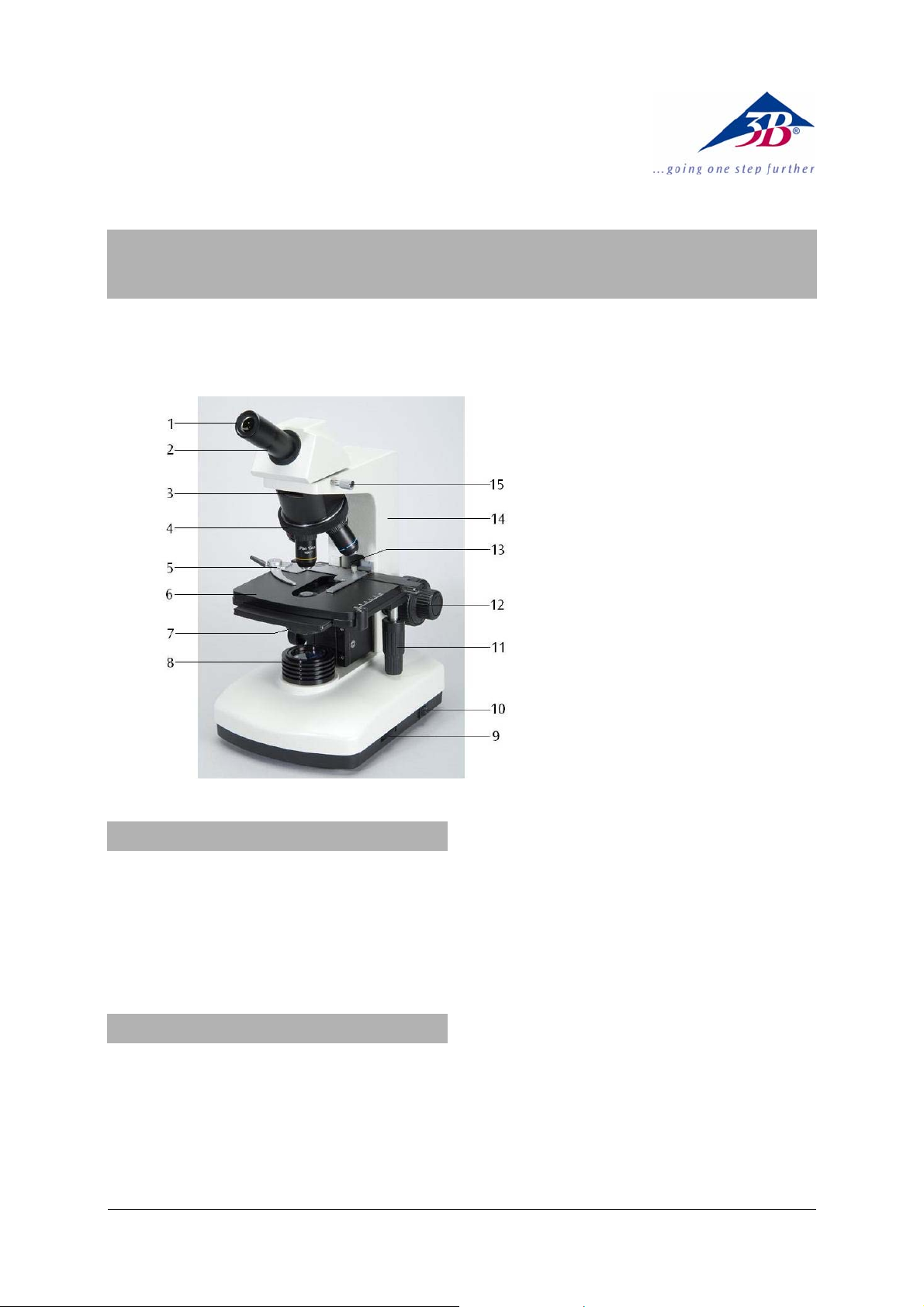
1 Eyepiece
2 Tube
3 Slot for inserting the analy-
ser
4 Revolver with objectives
5 Object guide
6 Object stage
7 Condensor with iris diaph-
ragm and filter holder
8 Lamp housing
9 Illumination control
10 Mains switch
11 1Coaxial movement control
for the specimen stage
12 Coarse and fine movement
controls with holding brake
13 Lock screw for object stage
14 Stand
15 Head lock screw
1. Safety notes
• For power supply use only electrical sockets
with ground contact.
Caution! The Stirling engine becomes hot during
use. Risk of burns!
• Do not touch the lamp during or immediately
after use.
2. Description, technical data
The monocular microscope allows twodimensional viewing of objects (thin sections of
plant or animal specimen) in 40x to 1500x magnification. It is fitted with polarisation equipment.
Stand: Robust, all metal stand with arm permanently connected to the base. Focussing by
means of separate knobs for coarse and fine
adjustment located on either side of the stand
and operated by rack and pinion drive with ball
bearings and retaining lever, adjustable stopper
for protecting the object slides and objective.
Focus range: 15mm, resolution of fine focussing
adjustment: 0.002 mm
Tube: Monocular inclined 30°, head rotation
360°
Polarisation equipment: Polariser and analyser
Eyepiece: Wide field eyepieces WF 10x 18 mm
and 15x 13 mm
Objectives: Inverted objective revolver with 4
plan achromatic objectives 4x / 0.10, 10x / 0.25,
40x / 0.65, 100x / 1.25 (oil)
Magnification: 40x – 1500x
Object stage: x-y cross table, 155 x 145 mm
with object guide and coaxial adjustment knobs
1
2
,
Page 2

perpendicular to the object stage, adjustment
range 50 x 76 mm
2
Illumination: Adjustable 6 V, 20 W halogen
lamp incorporated into the base, universal 85 to
265 V, 50/60 Hz power supply
Condenser: Abbe condenser N.A.1.25 NA 0.65
with iris diaphragm , filter holder and blue filter,
focussed via rack and pinion drive
Dimensions: 256 x 190 x 378 mm³ approx.
Weight: 6 kg approx.
3. Unpacking and assembly
The microscope is packed in a molded styrofoam container.
• Take the container out of the carton remove
the tape and carefully lift the top half off the
container. Be careful not to let the optical
items (objectives and eyepieces) drop down.
• To avoid condensation on the optical com-
ponents, leave the microscope in the original
packing to allow it to adjust to room temperature.
• Using both hands (one around the pillar and
one around the base), lift the microscope
from the container and put it on a stable
desk.
• The objectives will be found within individual
protective vials. Install the objectives into the
microscope nosepiece from the lowest
magnification to the highest, in a clockwise
direction from the rear.
• Put the head onto the top of the stand and
tighten the head-lock-screw. Insert the eyepiece into the tube.
4. Operation
4.1 General information
• Set the microscope on a level table.
• Place the object to be observed in the centre
of the specimen stage and clamp it to the
object guide.
• Connect the mains cable to the net and turn
on the switch to get the object illuminated.
• Make certain that the specimen is centered
over the opening in the stage.
• To obtain a high contrast, adjust the back-
ground illumination by means of the iris diaphragm and the variable illumination control.
• Rotate the nosepiece until the objective with
the lowest magnification is pointed at the
specimen. There is a definite “click” when
each objective is lined up properly.
NOTE: It is best to begin with the lowest power
objective. This is important to reveal general
structural details with the largest field of view
first. Than you may increase the magnification
as needed to reveal small details. When 100x
(oil) objective is chosen, objective oil must be
dripped onto the slide.
To determine the magnification at which you are
viewing a specimen, multiply the power of the
eyepiece by the power of the objective.
• Adjust the holding brake to give a suitable
degree of tightness in the focusing mechanism.
• Adjust the coarse-focusing-knob which
moves the stage up until the specimen is focused. Be careful that the objective does not
make contact with the slide at any time. This
may cause damage to the objective and/or
crack your slide.
• Adjust the fine-focusing-knob to get the im-
age more sharp and more clear.
• Colour filters may be inserted into the filter
holder for definition of specimen parts.
Swing the filter holder out and insert colour
filters.
• Use the knobs of the mechanical stage to
move the slide side-, back- and forwards.
The vernier provides acc urate loc ation of the
specimen area.
• Always turn off the light immediately after
use.
• Be careful not to spill any liquids on the mi-
croscope.
• Do not mishandle or impose unnecessary
force on the microscope.
• Do not wipe the optics with your hands.
• Do not attempt to service the microscope
yourself.
4.2 Using the polarisation equipment
• Insert the analyser into the slot on the re-
volving nosepiece.
• Place the polarising filter on the rim aperture
of the light source.
• Rotate the polariser until the planes of the
polariser and the analyser are exa ctly crossed,
so that one sees a black background.
Any object with a doubly-refracting (birefringent)
structure should now appear brightly illuminated
against the dark background. If that does not
occur, it is possible that the direction of light
vibration of the object coincides with the polarisation direction. Whether or not that is the case
can be tested by rotating the polariser or the
specimen itself.
A birefringent object, when rotated continuously,
shows up brightly after each 90° rotation and is
2
Page 3

dark between these positions. In contrast, objects that are isotropic and not birefringent remain dark in all positions.
4.3 Changing the lamp and fuse
4.3.1 Changing the lamp
• Turn off the power switch, unplug the mains
plug and let the lamp cool down to avoid being burnt.
• For safety reasons, remove the eyepiece.
• To change the lamp lay the microscope on
its back to reach the lid on the bottom side.
• Loosen screw C of the lamp socket and
push it outwards so that it is in the position
shown in Fig.1.
• Loosen screw A and open the cover.
• To remove the halogen lamp, use a cloth or
similar material. Do not touch the bulb with
the bare hand.
• Lift out the halogen lamp and replace it with
a new one.
• Close the cover and secure it with the
screw.
• Push the lamp socket back into the original
position and tighten screw C.
C
5. Storage, cleaning and disposal
• Keep the microscope in a clean, dry and
dust free place.
• When not in use always cover the micro-
scope with the dust cover.
• Do not expose it to temperatures below 0°C
and above 40°C and a max. relative humidity of over 85%.
• Always unplug the mains plug before clean-
ing or maintenance.
• Do not clean the unit with volatile solvents or
abrasive cleaners.
• Do not disassemble objective or eyepieces
to attempt to clean them.
• Use a soft linen cloth and some ethanol to
clean the microscope.
• Use a soft lens tissue to clean the optics.
• The packaging should be disposed of at
local recycling points.
• Should you need to
dispose of the equipment itself, never throw
it away in normal domestic waste. Local
regulations for the disposal of electrical
equipment will apply.
B
A
Fig. 1 Lamp socket cover: A - knurled screw, B - ventilation slots, C - securing screws of lamp-holder
4.3.2 Changing the fuse
• Turn off the power switch and unplug the
mains plug.
• Unscrew the fuse holder on the back of the
stand base with a screwdriver.
• Replace the fuse and reinsert the holder in
its socket.
3B Scientific GmbH • Rudorffweg 8 • 21031 Hamburg • Germany • www.3bscientific.com
Subject to technical amendments
© Copyright 2013 3B Scientific GmbH
Page 4

 Loading...