

Page 1
3B SCIENTIFIC3B SCIENTIFIC
3B SCIENTIFIC®
3B SCIENTIFIC3B SCIENTIFIC
Low-temperature Stirling motor kit U10061
Instruction sheet
08/05 ALF
PHYSICSPHYSICS
PHYSICS
PHYSICSPHYSICS
cm
bo bp
bq
br
bs
bt
cp
bu
co
bn
bm
bl
9
cn
8
7
6
5
4
cr
cl
cq
ct
cs
1
2
3
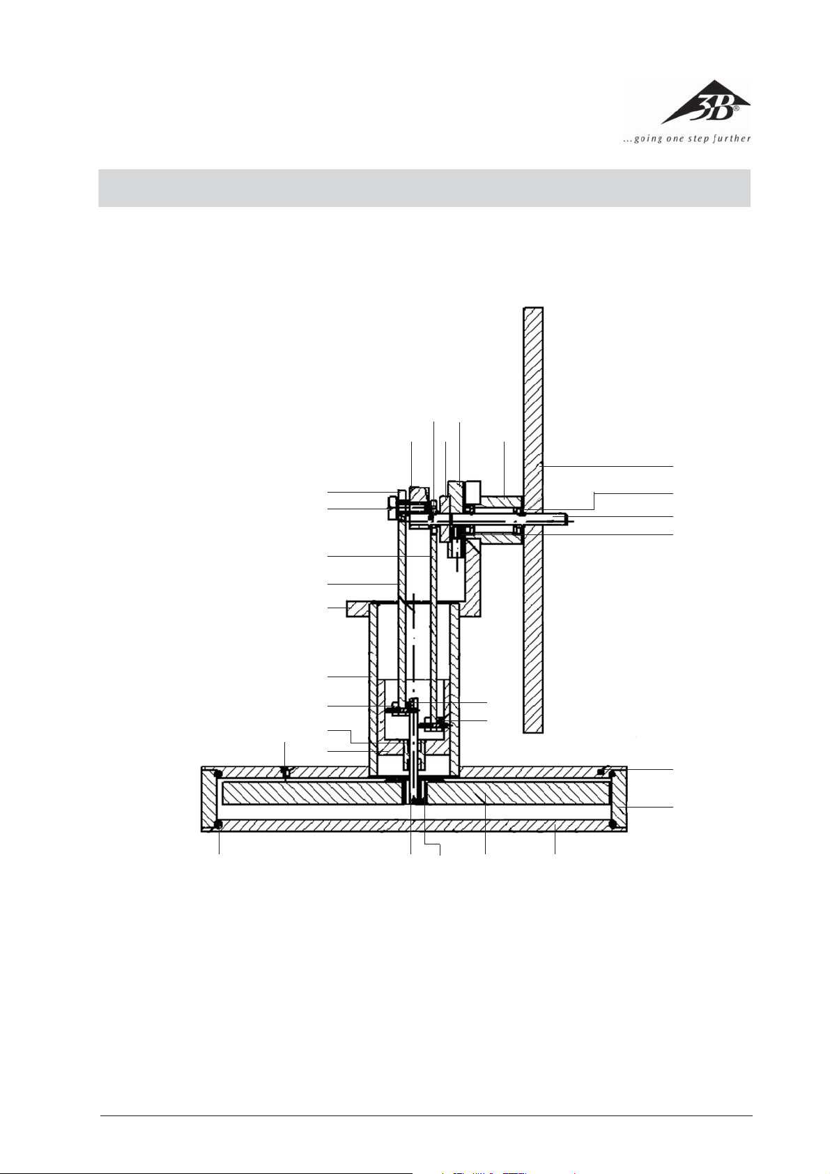
1 Top plate
2 Wall of housing
3 Bottom plate
4 Displacer
5 Displacer socket
6 Displacer rod
7 Main piston
8 Main piston socket
9 Main cylinder
bl Bracket
bm Short connecting rod
bn Long connecting rod
bo Crank face
bp Insert
bq Crank disc
br Bearing socket
bs Flywheel
bt Gaskets (2x)
bu Ball bearings (4x)
cl Crankshaft
cm Crankshaft journal
5
cn Cylinder rods 1x8 (2x)
co Cylinder head screw M3x8
cp Countersunk screw M2x3
cq Threaded rod M2x5
cr Washers (6x)
cs Wide clamping discs (3x)
ct Narrow clamping disc
Page 2

The low-temperature Stirling motor demonstrates how a
Stirling motor operates as well as the principles of its
design.
1. Description, technical data
The low-temperature Stirling motor is set in motion even
by the heat of the human hand. It only requires a temperature difference of 5°C between the ground and the
top plate. The main cylinder is made of precision glass.
The displacer cylinder and the flywheel are transparent
acrylic so that the motion of the main piston, the displacer piston and the crank drive can all be seen clearly.
The crankshaft and connecting rods have miniature precision bearings to minimise friction. Due to the matt black
coating of the top plate, the Stirling motor can also be
operated using solar power.
Speed: 80 rpm approx. at ∆T 10ºC
Flywheel: 110 mm Ø
Dimensions: 138 mm x 110 mm Ø
2. Assembly instructions
2.1 Finishing
• All components with burred edges should have their
burrs filed off using a flat or triangular file.
• File down the surfaces on any workpieces if desired.
2.2. Assembly
2.2.1. Making a permanent assembly
• We recommend use of “UHU plus endfest 300”, “UHU
plus schnellfest” or similar 2-component epoxy resin
adhesive. In order to prevent damage to the coating
of the top plate, avoid any contact with solvents.
Owing to the differing expansion coefficients of the
materials, do not allow any of the components to
increase temperature during the hardening of the
adhesive. Aluminium will contract much more on
cooling than the glass cylinder, thus creating tension
in the glass leading to a decrease in the internal diameter of the main cylinder or possibly even causing
it to break. Glueing together to make the connections
should generally be performed at a consistent temperature of approximately 20°C.
1. Glue the main cylinder 9 to the bracket bl at room
temperature, then glue it to the 1 top plate.
2. Fasten the bearings bu inside the bearing socket br.
Force the ball race bu onto the crankshaft cl and
apply a thin adhesive film to three points on its outer
surface. Then push the ball race bu into one of the
two recesses of the bearing socket br. Any surplus
adhesive should be removed with a cloth soaked in
white spirit. Always wipe towards the outside when
doing this to prevent adhesive penetrating into the
bearings. From the other side push another ball race
bu onto the crankshaft cl and proceed as before. To
achieve best alignment of the two ball races bu leave
the crankshaft cl in the same position until the
adhesive has hardened.
3. Glue the insert bp into its recess in the crank disc bq.
Make sure that both surfaces being adhered are flush
together. There is a marking on the outer surface of
the insert bp. Align this marking along the transverse
bore of the crank disc bq .
4. Next, glue the crank shaft journal cm into the bore of
the insert bp.
5. Glue cylinder rods cn into the bore of the displacer
rod 6 and the main piston 7. No adhesive residue
whatever may remain on the running surfaces of the
cylinder rods cn. Push the cylinder rods into the
relevant bores till about 2 mm protrudes and apply a
small amount of adhesive to the protruding end. Then
push the cylinder rod cn into its correct position and
remove any surplus adhesive as above. Make sure
the cylinder rod cn of the main piston 7 is glued so
that it is slightly recessed so that it does not damage
the running surface of the main cylinder 9 later on.
6. When glueing the displacer socket 5 into the bore
of the displacer 4 proceed as follows. Push the
displacer rod 6 into the main piston’s socket 8
then push the main piston 7 into the main cylinder
9. Next, attach the displacer socket 5 to the dis-
placer rod 6. Glue this into the bore of the displacer
4 and position the complete module on the under-
side of the displacer 4 so that the displacer 4 just
touches the top plate 1. Leave these components
in this position until the adhesive has fully hardened
to ensure that the displacer 4 and top plate 1
remain parallel.
7. Finally glue the bearing socket br into the bore of
the bracket bl.
2.2.2. Making a temporary assembly
1. Press the ball race bu into the bore of the connecting
rods bm and bn. All the bearings are supplied without lubricant. To ensure that the bearings bu run
smoothly always use the supplied, semi-spherical
washers cr in the assembly. The spherical side of the
washers cr should face the ball bearing bu.
2. Push the first washer cr, the long connecting rod
bn, the second washer cr and the face of the crank
bo onto the crankshaft journal cm.The small mark-
ing on the edge of the crank face bo should be to the
right of the crankshaft journal cm as seen in the
diagram.
3. Push the first wide clamping disc cs, the long connecting rod bn and the second wide clamping disc
cs onto the cylinder rod cn of the main piston 7,
having lubricated it slightly first. The diameter of the
6
Page 3

clamping disc’s cs bore is greater on one side than
the other so that it is easier to slide it onto the cylinder rod cn.
4. Slide the piston rod 7 into the main cylinder 9.
The main piston
with no lubrication so do not attempt to apply any
lubricant! The entire mechanism is also designed to
run with no lubrication so that no lubricant is necessary.
5. Now attach the crank disc bq with its threaded rod
77
7 moves inside the cylinder
77
99
9
99
cq to the crankshaft cl having first inserted a wash-
er cr. One more washer cr and the flywheel bs
should now be slid onto the other side of the crankshaft cl, making sure that there is as little axial play
as possible. If necessary, attach the flywheel bs to
the crankshaft cl with a little bit of glue.
6. The narrow clamping disc ct, the short connecting
rod bm, and the third wide clamping disc cs are next
to be slid onto the cylinder rod cn of the displacer
6, having first applied a little lubricant. Then slide
the displacer rod 6 into the main piston socket 8.
7. Now attach the short connecting rod bm to the crank
face bo separated by a washer cr using the cylinder
head screw co.
8. Carefully slide the displacer socket 5 onto the displacer rod 6, having first glued it into the displacer
4 itself.
9. Lay the O-ring gaskets bt inside the bottom plate
3 and press them into the side of the housing 2
using constant, firm pressure. To make this easier,
the O-ring gasket bt can first be lubricated with some
washing-up liquid.
10. Press the top plate 1 into the other side of the
housing 2 in a similar way. This connection can be
undone when necessary, by pushing a small wedge
(e.g. a small screwdriver) between the top plate 1
and the housing 2. If necessary a small opening
can be filed into the side of the housing 2 to make
inserting the tool easier.
2.3. Fine adjustment
• Fine adjustment is required to ensure that there is
only minimal separation between the displacer 4
and the top or bottom plate.
• After aligning the marking to the insert bp and the
crank face bo the stroke of the displacer should be
slightly too short. By turning the crank face bo on
the crankshaft journal a little bit it can be made longer (see exploded view, next page).
• Turning the flywheel bs afterward forces the dis-
placer socket 5 onto the displacer rod 6 when the
displacer 4 meets the top plate 1.
• Make the stroke of the displacer long enough so that
in one revolution the displacer 4 touches gently
against both the top plate and the bottom plate.
• Then shorten the stroke very slightly by turning the
crank face bo back a tiny bit.
• The displacer 4 and the top or bottom plate should
now be separated by a very small but even amount.
• Finally, turn the crankshaft cl so that the main pis-
ton 7 is in the middle of its stroke. Then firmly
screw the countersunk screw cp into the top plate
1.
3. Test of functionality
• Place the Stirling motor on the palm of your hand or
a surface that is heated, e.g. on top of a cup of hot
water.
• After about 1-2 minutes the base plate should have
heated up sufficiently. On hot days, the temperature
difference may not be great enough. If so cool the
top plate with a damp cloth.
• Spin the flywheel clockwise (looking towards the crank-
shaft).
• The Stirling motor rotates in an anti-clockwise direc-
tion when the top plate is heated, e.g. by sunlight or
by a lamp. In this instance, place the Stirling motor
on a cool surface such as a windowsill.
4. Storage and cleaning
• The Stirling motor requires no lubrication.
• Store the Stirling motor in a dust-free location.
• To clean the Stirling motor use a moist cloth, possibly
with some mild soap. Never clean acrylic components
using solvents or aggressive cleaning agents.
7
Page 4

6
co
cs
cn
5
cr
bu
cr
bo
ctbm
cr
bu
cm
cs
cr
bp
bq
cr
bu
bn
cs
cn
7
8
4
br
cr
cl
bu
bs
cq
bl
9
cp
1
V
V: Stroke increase;
M: Markers
bo
bt
2
bt
M
3
3B Scientific GmbH • Rudorffweg 8 • 21031 Hamburg • Germany • www.3bscientific.com • Technical amendments are possible
8
 Loading...