

Page 1
3B SCIENTIFIC
Instruction sheet
04/09 THL/ALF
1. Safety instructions
®
PHYSICS
Launcher S U8400930
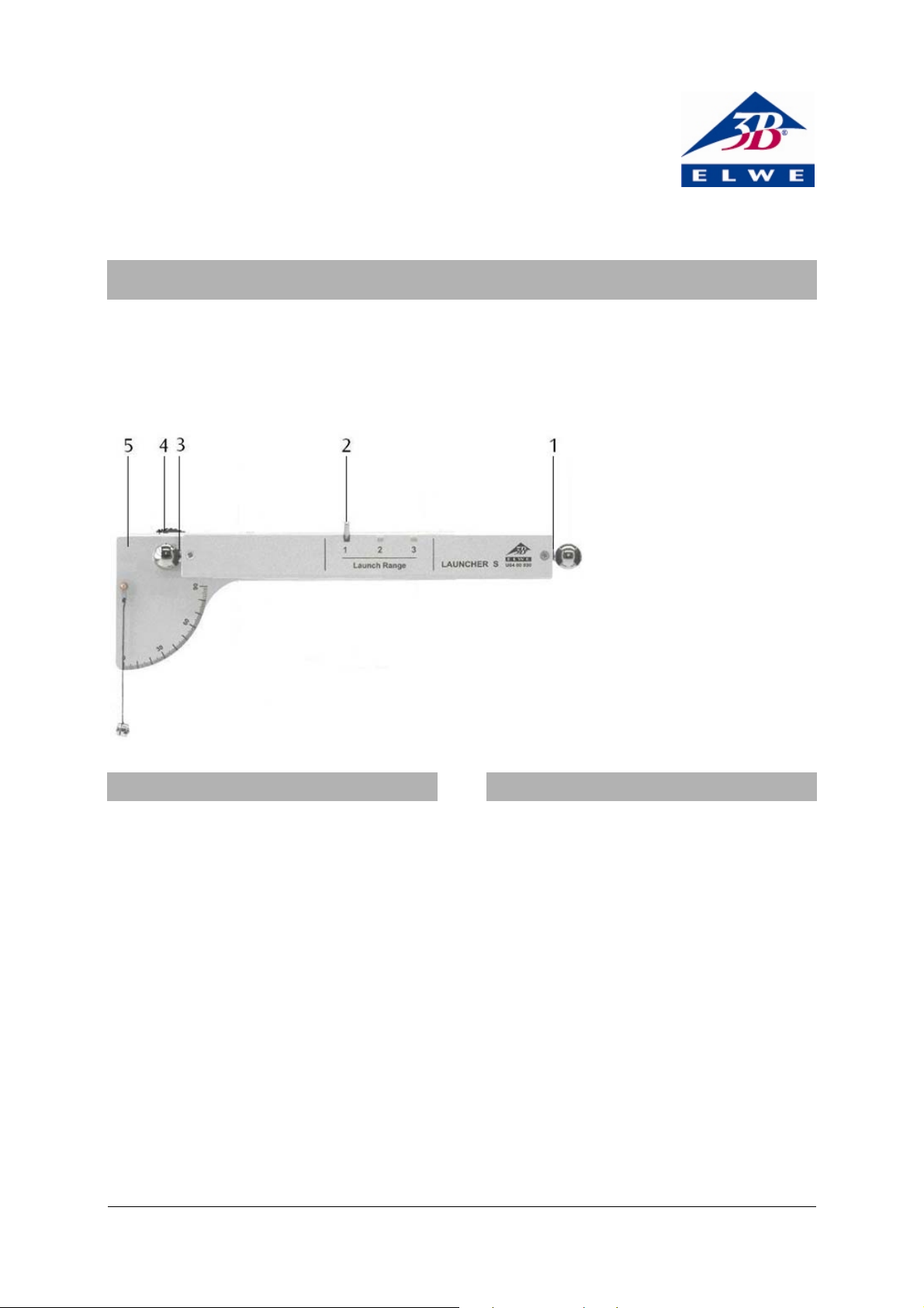
1 Rear magnetic holder with
ball
2 Release trigger
3 Front magnetic holder with
ball
4 Locking screw
5 Angle scale with plumbline
2. Description
The acceleration of the ball is quite small, and
therefore there is no risk of injuries. However, the
launcher must not be directed towards people
when it is loaded.
The target area of the ball must always be
uncluttered and clearly visible.
There must be no breakable articles in the target
area of the launcher.
• Ensure that there is a clear distance of at least
4 m in front of the launcher.
• Remove all breakable articles from the area in
front of the launcher.
When it is released, the trigger flies forward
rapidly.
• Only hold the part of the launcher behind the
release trigger.
The launcher S is used for investigating vertical,
oblique and horizontal throwing trajectories, and
for demonstrating the independent superposition
of horizontal and vertical components of motion.
A choice can be made between three different
launching accelerations by engaging the release
trigger in the corresponding notch. The angle of
elevation of the launch is continuously adjustable
and can be read on the angle scale by means of a
plumb-line.
Until the launch, the ball is held magnetically at
the launch position. When the angle is adjusted the
launch position remains unchanged, as the fulcrum
is on the horizontal axis of the ball. Thus, changing
the angle has no effect on the height from which
launching occurs. In the case of horizontal
launching of a ball, a second ball can be released
simultaneously from the rear end of the launcher
beam in free fall, and this lands on the table at the
same time as the launched ball.
1
Page 2
3. Equipment supplied
1 Launcher S
3 Steel balls
4. Technical data
Launch angle: 0° – 90°
Maximum range: 4 m
Projectile: steel ball, 16 mm dia.
Mass of ball: 16.7 g
Approx. dimensions: 280x90x90 mm³
Total weight: approx. 950 g
5. Apparatus also required
2 Stainless steel rods, 470 mm U15002
2 Table clamps U13260
or
2 Stand bases, A-shaped U8611150
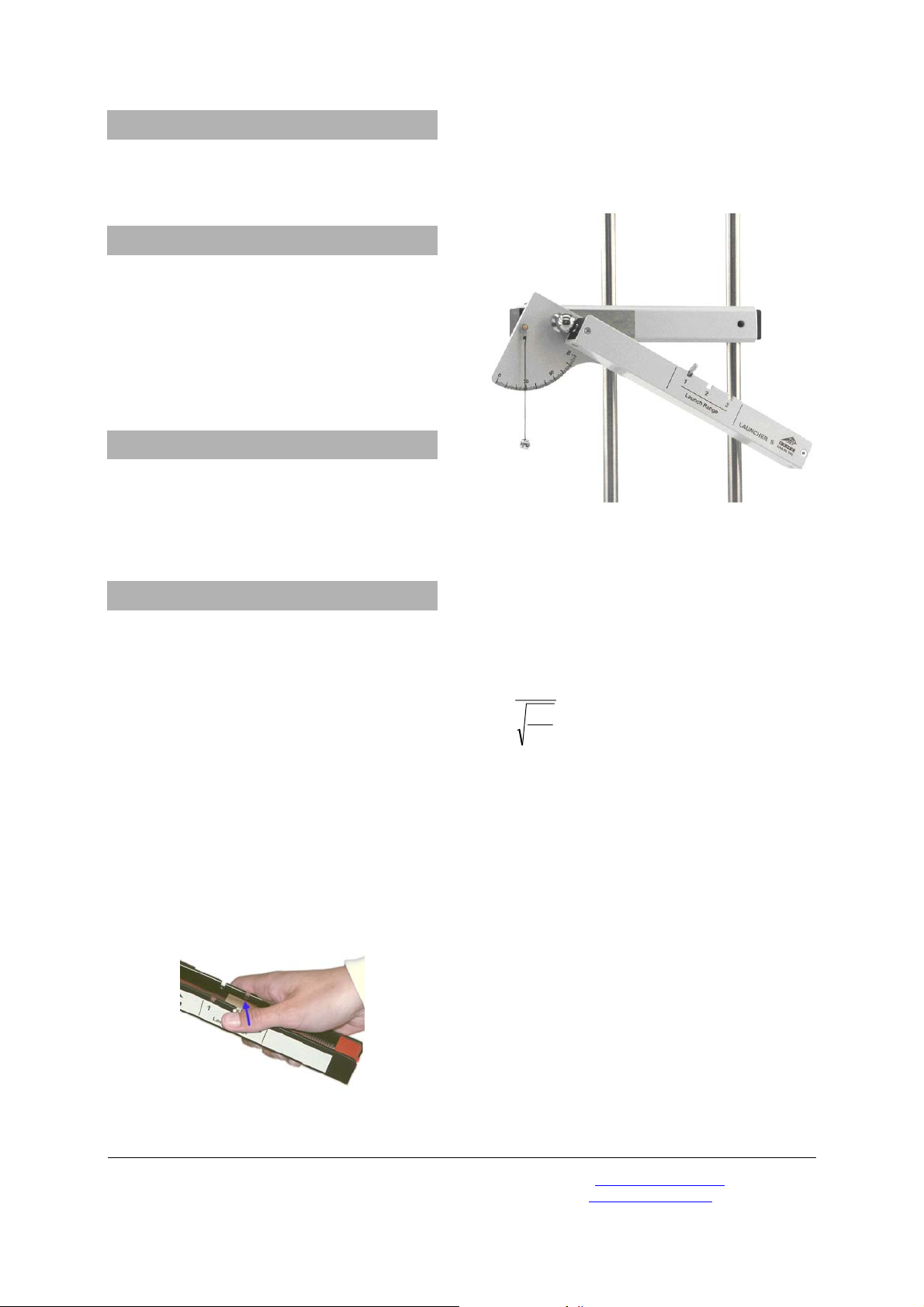
6. Operation
6.1 General instructions
• Using the clamps or stand bases, set up the
launcher securely on a level surface.
• Set the required launch angle by loosening the
locking screw slightly, adjusting the angle, and
re-tightening the screw.
• Stretch the launching spring by sliding the
release trigger and engaging it in notch 1, 2 or
3 according to the desired launching
acceleration.
• To release the ball, push the release trigger
upward by pressing on the side of it with your
thumb.
Fig. 1 Releasing the launch mechanism
6.2 Oblique, vertical and horizontal launching
• Place the ball on the front magnetic holder
and set the required launch angle.
• Release the ball.
Fig. 2 Experiment set-up for oblique launching
6.3 Determining the launch velocity
If the launcher is set in the horizontal launching
position, the launch velocity can be calculated
from the height of the launcher and the range. The
change of the horizontal velocity during the flight
can be neglected.
s
v⋅=
h
2
g
v = launch velocity
s = range (distance reached on table)
h = height of launcher
g = 9.81 m/s²
6.4 Comparison between free fall and
horizontal throw
• Place balls on both the front and the rear
magnetic holders, and set the launch angle to
0°.
• Release both balls simultaneously.
• Listen for the sound of the impact of the two
balls.
If the horizontal setting of the launcher is precise,
it is hardly possible to detect a difference between
the two impacts (i.e., the time of fall is the same for
both).
Elwe Didactic GmbH • Steinfelsstr. 6 • 08248 Klingenthal • Germany • www.elwedidactic.com
3B Scientific GmbH • Rudorffweg 8 • 21031 Hamburg • Germany • www.3bscientific.com
Subject to technical amendments
© Copyright 2009 3B Scientific GmbH
 Loading...