

Page 1

3B SCIENTIFIC
Bedienungsanleitung
04/09 THL/ALF
1. Sicherheitshinweise
®
PHYSICS
Wurfgerät S U8400930
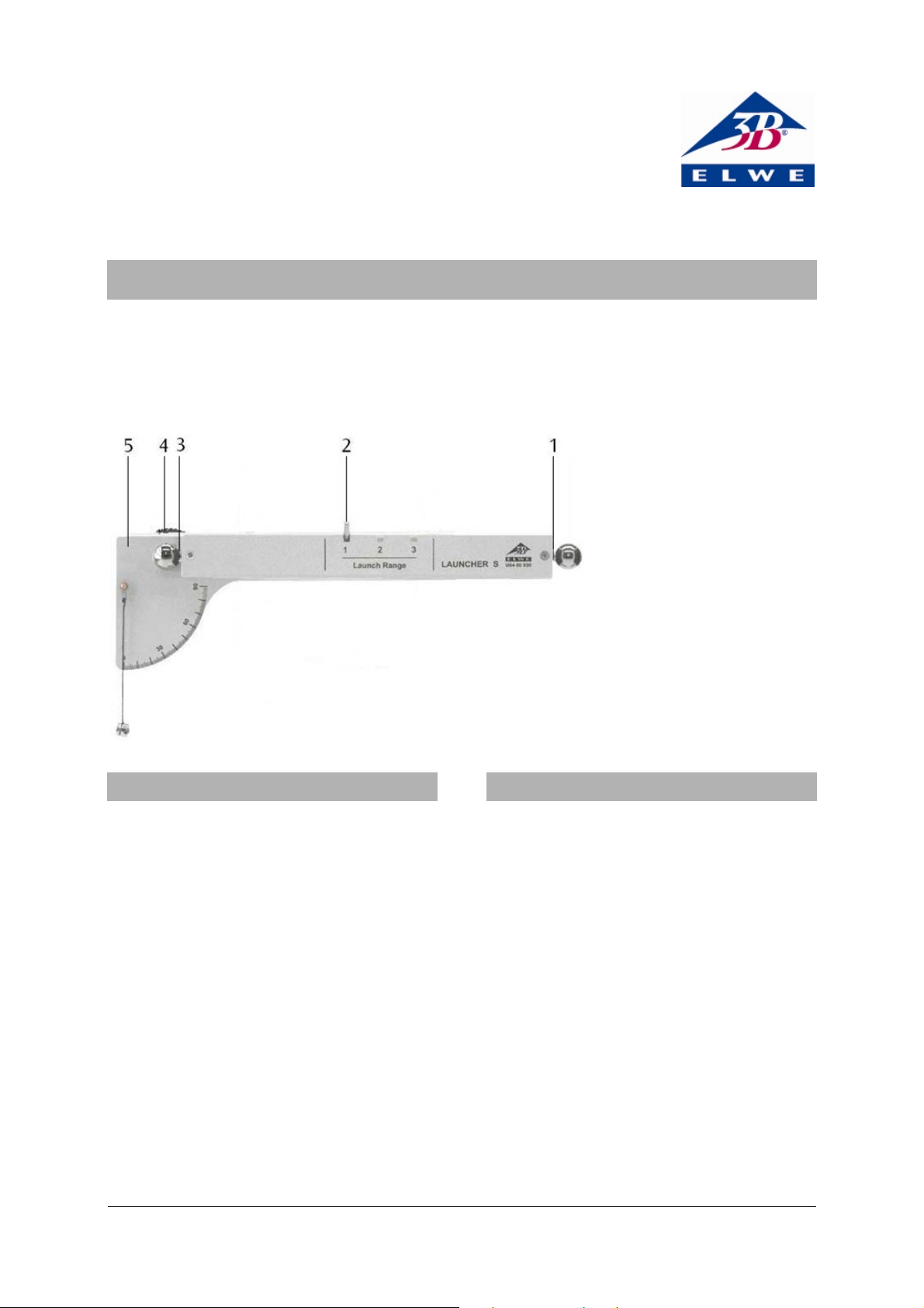
1 Hintere Magnetaufnahme mit
Kugel
2 Auslösestift
3 Vordere Magnetaufnahme
mit Kugel
4 Feststellschraube
5 Winkelskala mit Lot
2. Beschreibung
Die Beschleunigung der Kugel ist gering, so dass
Verletzungen für den Menschen auszuschließen
sind. Dennoch darf das schussbereite Wurfgerät
nicht auf Personen gerichtet werden.
Der Wurfbereich der Kugel muss stets gut überschaubar sein.
Zerbrechliche Gegenstände dürfen sich nicht im
Wurfbereich des Gerätes befinden.
• Vor dem Wurfgerät mindestens 4 m frei halten.
• Zerbrechliche Gegenstände vor dem Wurfgerät
entfernen.
Der Auslösestift schnellt nach dem Auslösen nach
vorn.
• Wurfgerät nur hinter dem Auslösestift anfassen
Das Wurfgerät S dient zur Untersuchung des senkrechten, schrägen und waagerechten Wurfes sowie
zur Demonstration der unabhängigen Überlagerung von horizontaler und vertikaler Bewegung.
Drei verschiedene Abwurfgeschwindigkeiten können durch Einrasten des Auslösestifts in die entsprechende Kerbe gewählt werden. Der Abschusswinkel ist stufenlos einstellbar und an der Winkelskala über einen Faden mit Lot ablesbar.
Die Kugel ist bis zum Abschuss magnetisch am
Abschusspunkt fixiert. Durch die Winkeleinstellung
bleibt die Abschussposition unverändert, da sich
der Drehpunkt auf der horizontalen Kugelachse
befindet. Eine Winkeländerung hat demnach keinen Einfluss auf die Abwurfhöhe. Beim waagrechten Abschuss einer Kugel kann zeitgleich an der
Rückseite des Schussbolzens eine zweite Kugel im
freien Fall ausgelöst werden, die auch zeitgleich
mit der abgeschossen Kugel aufschlägt.
1
Page 2
3. Lieferumfang
1 Wurfgerät S
3 Stahlkugeln
4. Technische Daten
Abwurfwinkel: 0° – 90°
Maximale Wurfweite: 4 m
Wurfkörper: Stahlkugel, 16 mm Ø
Kugelmasse: 16,7 g
Abmessungen : ca. 280x90x90 mm³
Gesamtmasse: ca. 950 g
5. Zusätzlich erforderliche Geräte
2 Stativstangen, 470 mm U15002
2 Tischklemmen U13260
oder
2 Stativfüße U8611150
6. Bedienung
6.1 Allgemeine Hinweise
• Wurfgerät mit Hilfe des Stativmaterials fest an
einer Arbeitsplatte montieren oder auf einer
ebenen Unterlage aufbauen.
• Zum Einstellen des Abschusswinkels die Fest-
stellschraube etwas lockern, Winkel einstellen
und Feststellschraube wieder anziehen.
• Abschussfeder mit dem Auslösestift spannen
und je nach gewünschter Abschussgeschwindigkeit in Kerbe 1, 2 oder 3 einrasten lassen.
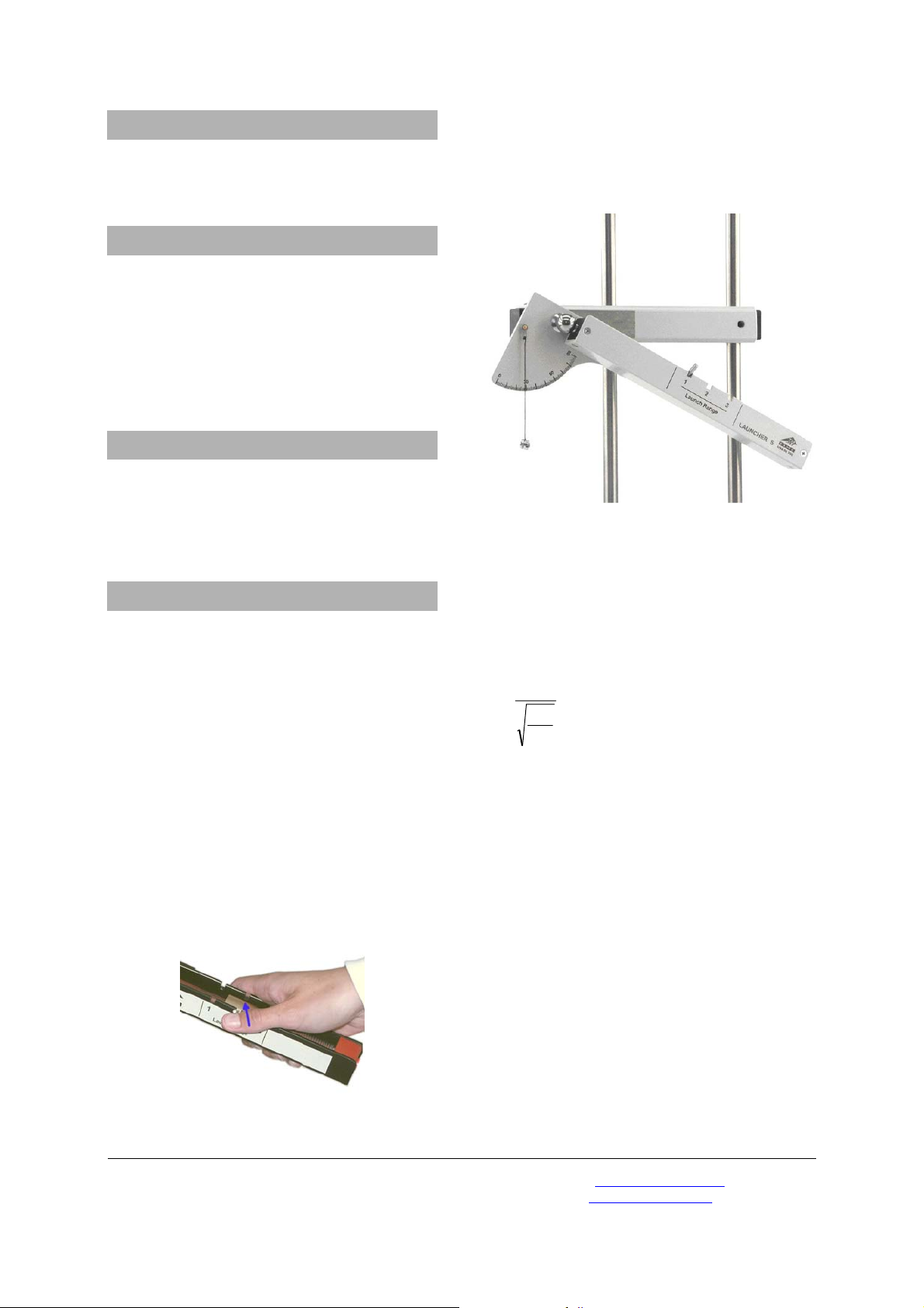
• Zum Auslösen der Kugel den Auslösestift mit
dem Daumen durch seitliches Drücken nach
oben schieben.
Fig. 1 Auslösen der Abschussvorrichtung
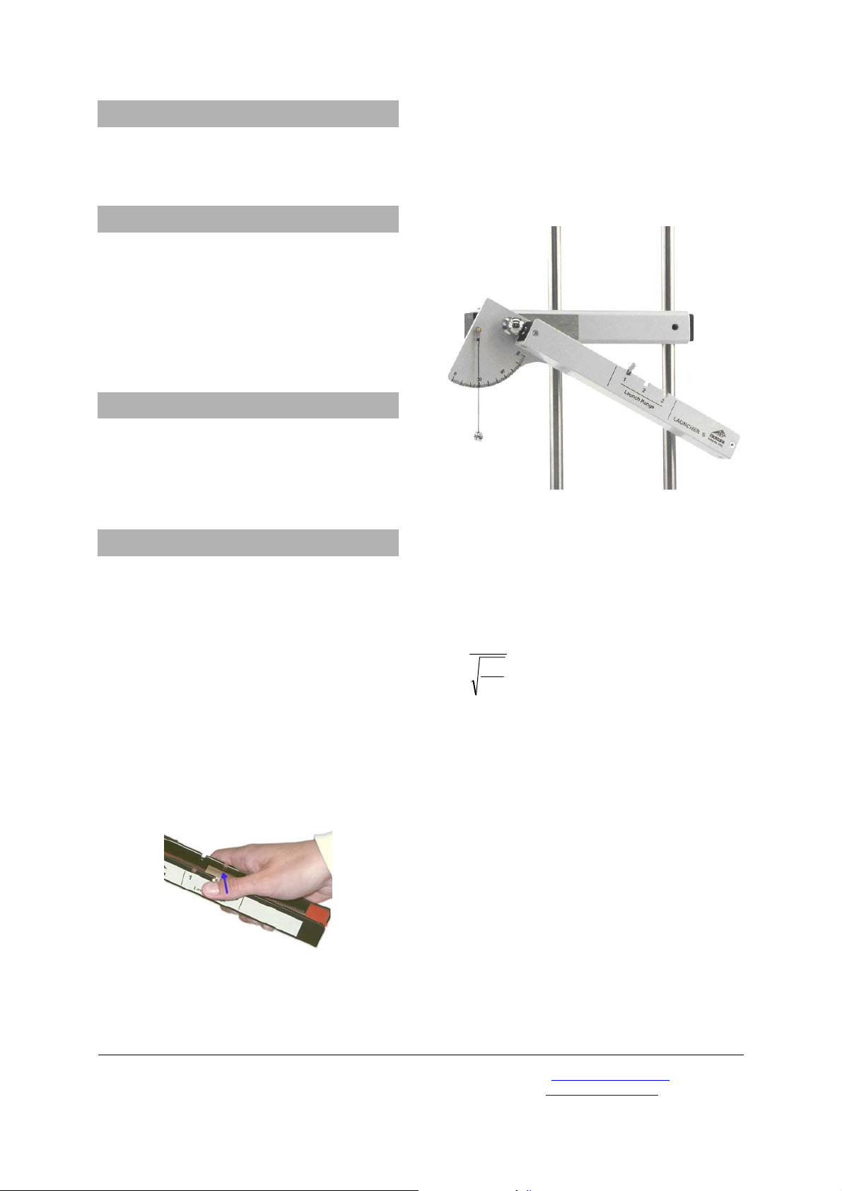
6.2 Schräger, senkrechter und waagrechter
Wurf
• Kugel an der vorderen Magnetaufnahme auf-
setzen und gewünschten Abschusswinkel einstellen.
• Kugel auslösen.
Fig. 2 Experimenteller Aufbau schräger Wurf
6.3 Bestimmung der Abwurfgeschwindigkeit
Die Abwurfgeschwindigkeit kann über die Wurfweite und Abwurfhöhe bei waagerechter Abschussposition ermittelt werden. Die Geschwindigkeitsänderung während des Wurfes ist vernachlässigbar.
s
v⋅=
h
2
g
v = Abwurfgeschwindigkeit
s = Wurfweite
h = Abwurfhöhe
g = 9,81 m/s²
6.4 Vergleich zwischen Freiem Fall und waagerechtem Wurf
• Kugeln sowohl an der vorderen als auch an der
hinteren Magnetaufnahme aufsetzen und Abschusswinkel auf 0° einstellen.
• Kugeln auslösen.
• Auf das Aufschlaggeräusch beider Kugeln ach-
ten.
• Die akustische Trennung der beiden Ereignisse
ist bei guter horizontaler Ausrichtung des
Wurfgerätes kaum noch möglich (gleiche Fallzeiten).
Elwe Didactic GmbH • Steinfelsstr. 6 • 08248 Klingenthal • Deutschland • www.elwedidactic.com
3B Scientific GmbH • Rudorffweg 8 • 21031 Hamburg • Deutschland • www.3bscientific.com
Technische Änderungen vorbehalten
© Copyright 2009 3B Scientific GmbH
Page 3
3B SCIENTIFIC
Instruction sheet
04/09 THL/ALF
1. Safety instructions
®
PHYSICS
Launcher S U8400930
1 Rear magnetic holder with
ball
2 Release trigger
3 Front magnetic holder with
ball
4 Locking screw
5 Angle scale with plumbline
2. Description
The acceleration of the ball is quite small, and
therefore there is no risk of injuries. However, the
launcher must not be directed towards people
when it is loaded.
The target area of the ball must always be
uncluttered and clearly visible.
There must be no breakable articles in the target
area of the launcher.
• Ensure that there is a clear distance of at least
4 m in front of the launcher.
• Remove all breakable articles from the area in
front of the launcher.
When it is released, the trigger flies forward
rapidly.
• Only hold the part of the launcher behind the
release trigger.
The launcher S is used for investigating vertical,
oblique and horizontal throwing trajectories, and
for demonstrating the independent superposition
of horizontal and vertical components of motion.
A choice can be made between three different
launching accelerations by engaging the release
trigger in the corresponding notch. The angle of
elevation of the launch is continuously adjustable
and can be read on the angle scale by means of a
plumb-line.
Until the launch, the ball is held magnetically at
the launch position. When the angle is adjusted the
launch position remains unchanged, as the fulcrum
is on the horizontal axis of the ball. Thus, changing
the angle has no effect on the height from which
launching occurs. In the case of horizontal
launching of a ball, a second ball can be released
simultaneously from the rear end of the launcher
beam in free fall, and this lands on the table at the
same time as the launched ball.
1
Page 4
3. Equipment supplied
1 Launcher S
3 Steel balls
4. Technical data
Launch angle: 0° – 90°
Maximum range: 4 m
Projectile: steel ball, 16 mm dia.
Mass of ball: 16.7 g
Approx. dimensions: 280x90x90 mm³
Total weight: approx. 950 g
5. Apparatus also required
2 Stainless steel rods, 470 mm U15002
2 Table clamps U13260
or
2 Stand bases, A-shaped U8611150
6. Operation
6.1 General instructions
• Using the clamps or stand bases, set up the
launcher securely on a level surface.
• Set the required launch angle by loosening the
locking screw slightly, adjusting the angle, and
re-tightening the screw.
• Stretch the launching spring by sliding the
release trigger and engaging it in notch 1, 2 or
3 according to the desired launching
acceleration.
• To release the ball, push the release trigger
upward by pressing on the side of it with your
thumb.
Fig. 1 Releasing the launch mechanism
6.2 Oblique, vertical and horizontal launching
• Place the ball on the front magnetic holder
and set the required launch angle.
• Release the ball.
Fig. 2 Experiment set-up for oblique launching
6.3 Determining the launch velocity
If the launcher is set in the horizontal launching
position, the launch velocity can be calculated
from the height of the launcher and the range. The
change of the horizontal velocity during the flight
can be neglected.
s
v⋅=
h
2
g
v = launch velocity
s = range (distance reached on table)
h = height of launcher
g = 9.81 m/s²
6.4 Comparison between free fall and
horizontal throw
• Place balls on both the front and the rear
magnetic holders, and set the launch angle to
0°.
• Release both balls simultaneously.
• Listen for the sound of the impact of the two
balls.
If the horizontal setting of the launcher is precise,
it is hardly possible to detect a difference between
the two impacts (i.e., the time of fall is the same for
both).
Elwe Didactic GmbH • Steinfelsstr. 6 • 08248 Klingenthal • Germany • www.elwedidactic.com
3B Scientific GmbH • Rudorffweg 8 • 21031 Hamburg • Germany • www.3bscientific.com
Subject to technical amendments
© Copyright 2009 3B Scientific GmbH
Page 5

3B SCIENTIFIC
Lanceur balistique S U8400930
Instructions d’utilisation
04/09 THL/ALF
1. Consignes de sécurité
®
PHYSICS
1 Logement aimanté arrière
avec bille
2 Mécanisme déclencheur
3 Logement aimanté avant
avec bille
4 Vis de fixation
5 Échelle angulaire graduée
avec fil à plomb
2. Description
L'accélération de la bille est tellement faible qu'il
n'existe aucun risque de dommages corporels. Il
faudra toutefois veiller à ne pas diriger le lanceur
balistique prêt au lancement vers des personnes.
Il est indispensable que la zone de projection de la
bille reste toujours bien contrôlable.
Des objets fragiles ne doivent pas se trouver dans la
zone de projection de l'appareil.
• Veillez à respecter une distance libre d'au
moins 4 mètres devant le lanceur balistique.
• Retirez les objets fragiles se trouvant devant le
lanceur balistique.
Après son actionnement, le mécanisme
déclencheur bondit vers l'avant.
• Ne touchez donc le lanceur balistique que
derrière le mécanisme déclencheur.
Le lanceur balistique S sert à étudier la projection
verticale, oblique et horizontale ainsi qu'à faire
une démonstration de la superposition
indépendante des mouvements horizontaux et
verticaux.
Il est possible de sélectionner trois vitesses de
projection différentes en engageant le mécanisme
déclencheur dans l'encoche correspondante.
L'angle de lancement est réglable en continu et
peut être relevé sur l'échelle angulaire graduée
grâce à un fil à plomb.
Jusqu'à son lancement, la bille reste fixée
magnétiquement au point de lancement. Grâce au
réglage angulaire, la position de lancement ne
subit aucun changement, l'angle de rotation se
trouvant sur l'axe horizontal de la bille. Une
modification angulaire n'a donc aucune influence
sur la hauteur de lancement. Lors du lancement
horizontal d'une bille, il est possible de déclencher
simultanément (sur la face arrière du rivet pop) la
chute libre d'une deuxième bille qui percutera
simultanément la surface avec la bille lancée.
1
Page 6

3. Étendue de la livraison
1 lanceur balistique S
3 billes d'acier
4. Caractéristiques techniques
Angle de projection : Entre 0 et 90 degrés
Portée de projection maximale : 4 m
Projectile : Bille d'acier, diamètre de 16 mm
Masse de la bille : 16,7 g
Dimensionnements : d'environ 280 x 90 x 90
mm³
Masse totale : d'environ 950 g
5. Appareils supplémentaires nécessaires
2 tiges de statif, 470 mm U15002
2 étaux de fixation U13260
ou
2 pieds en forme de A U8611150
6. Manipulation
6.1 Remarques générales
• Montez le lanceur balistique à demeure sur un
plan de travail en utilisant les tiges de statif ou
montez-le sur une surface plane.
• Pour régler l'angle de lancement, desserrez
légèrement la vis de fixation, réglez l'angle,
puis resserrez cette vis.
• Serrez le ressort de lancement à l'aide du
mécanisme déclencheur, puis en fonction de la
vitesse de lancement souhaitée, engagez-le
dans l'encoche 1, 2 ou 3.
• Pour déclencher le lancement de la bille,
poussez le mécanisme déclencheur vers le haut
en exerçant une pression latérale avec votre
pouce.
Fig. 1 Déclenchement du mécanisme de lancement
6.2 Projection oblique, verticale et horizontale
• Placez la bille sur le logement aimanté avant,
puis réglez l'angle de lancement souhaité.
• Déclenchez le lancement de la bille.
Fig. 2 : Appareillage expérimental pour la projection
oblique
6.3 Détermination de la vitesse de projection
Pour une position verticale de lancement, il est
possible de déterminer la vitesse de projection en
faisant appel à la portée de projection et à la
hauteur de lancement. La modification de vitesse
au cours de la projection est négligeable.
s
v⋅=
h
2
g
v = vitesse de projection
s = portée de projection
h = hauteur de lancement
g = 9,81 m/s²
6.4 Comparaison entre la chute libre et la
projection verticale
• Placez une bille sur le logement aimanté avant
et l'autre sur le logement aimanté arrière, puis
réglez l'angle de lancement à 0 degré.
• Déclenchez le lancement des billes.
• Faites attention au bruit d'impact des deux
billes.
En présence d'un bon alignement horizontal du
lanceur balistique, il devient alors presque
impossible de distinguer acoustiquement les deux
événements (mêmes temps de chute).
Elwe Didactic GmbH • Steinfelsstr. 6 • 08248 Klingenthal • Allemagne • www.elwedidactic.com
3B Scientific GmbH • Rudorffweg 8 • 21031 Hamburg • Allemagne • www.3bscientific.com
Sous réserve de modifications techniques
© Copyright 2009 3B Scientific GmbH
Page 7

3B SCIENTIFIC
Apparecchio di lancio S U8400930
Istruzioni per l'uso
04/09 THL/ALF
1. Norme di sicurezza
®
PHYSICS
1 Supporto magnetico
posteriore con sfera
2 Perno di rilascio
3 Supporto magnetico anteriore
con sfera
4 Vite di bloccaggio
5 Scala angolare con piombo
2. Descrizione
L'accelerazione della sfera è ridotta, per cui si
possono escludere lesioni per le persone.
L'apparecchio di lancio, tuttavia, non deve essere
diretto verso persone.
L'area di lancio della sfera deve sempre essere ben
visibile.
Nell'area di lancio dell'apparecchio non devono
esservi oggetti fragili.
• Tenere liberi almeno 4 m davanti
all'apparecchio di lancio.
• Rimuovere eventuali oggetti fragili davanti
all'apparecchio di lancio.
Dopo il rilascio, il perno di rilascio scatta in avanti.
• Afferrare l'apparecchio di lancio soltanto
dietro al perno di rilascio.
L'apparecchio di lancio S consente l'analisi del
lancio verticale, obliquo e orizzontale e la
dimostrazione della sovrapposizione indipendente
di movimenti orizzontali e verticali.
Innestando il perno di rilascio nelle corrispondenti
tacche si possono selezionare tre diverse velocità di
lancio. L'angolo di lancio può essere impostato in
modo continuo e letto sulla scala angolare tramite
un filo con piombo.
La sfera è fissata in modo magnetico in
corrispondenza del punto di lancio fino al lancio.
Impostando l'angolo la posizione di lancio rimane
invariata, poiché il punto di rotazione si trova
sull'asse orizzontale della sfera. Una variazione
dell'angolo non ha quindi nessuna influenza
sull'altezza di lancio. Durante il lancio orizzontale
di una sfera, dalla parte posteriore del perno di
lancio è possibile lanciare contemporaneamente
una seconda sfera in caduta libera, la quale sempre
contemporaneamente si scontra con la sfera
lanciata.
1
Page 8

3. Fornitura
1 apparecchio di lancio S
3 sfere d'acciaio
4. Dati tecnici
Angolo di lancio: 0° – 90°
Gittata massima: 4 m
Corpo di lancio: Sfera d'acciaio, 16 mm Ø
Peso sfera: 16,7 g
Dimensioni: ca. 280x90x90 mm³
Peso totale: ca. 950 g
5. Altri apparecchi necessari:
2 aste di supporto, 470 mm U15002
2 morsetti da tavolo U13260
o
2 basi di supporto U8611150
6. Utilizzo
6.1 Indicazioni generali
• Montare l'apparecchio di lancio fisso su una
piastra di lavoro o una base piana mediante il
materiale di supporto
• Per impostare l'angolo di lancio allentare un
po' la vite di bloccaggio, impostare l'angolo e
stringere di nuovo la vite di bloccaggio.
• Tensionare la molla di lancio con il perno di
rilascio e innestarla in base alla velocità di
lancio desiderata nella tacca 1, 2 o 3.
• Per rilasciare la sfera con il pollice spostare
verso l'alto il perno di rilascio premendo
lateralmente verso l'alto.
Fig. 1 Rilascio del dispositivo di lancio
6.2 Lancio obliquo, verticale e orizzontale
• Collocare la sfera sul supporto magnetico
anteriore e impostare l'angolo di lancio
desiderato.
• Rilasciare la sfera
Fig. 2 Struttura sperimentale lancio obliquo
6.3 Determinazione della velocità di lancio
La velocità di lancio può essere determinata con la
gittata e l'altezza di lancio in caso di posizione di
lancio orizzontale. La variazione di velocità durante
il lancio è trascurabile.
s
v⋅=
h
2
g
v = velocità di lancio
s = gittata
h = altezza di lancio
g = 9,81 m/s²
6.4 Confronto tra caduta libera e lancio
orizzontale
• Collocare le sfere sia sul supporto magnetico
anteriore sia su quello posteriore e impostare
l'angolo di lancio a 0°.
• Rilasciare le sfere.
• Considerare il rumore dell'impatto delle due
sfere.
La distinzione acustica dei due eventi non è
possibile in caso di un buon allineamento
orizzontale.
Elwe Didactic GmbH • Steinfelsstr. 6 • 08248 Klingenthal • Germania • www.elwedidactic.com
3B Scientific GmbH • Rudorffweg 8 • 21031 Amburgo • Germania • www.3bscientific.com
Con riserva di modifiche tecniche
© Copyright 2009 3B Scientific GmbH
Page 9

3B SCIENTIFIC
Aparato de tiro S U8400930
Instrucciones de uso
04/09 THL/ALF
1. Advertencias de seguridad
®
PHYSICS
1 Alojamiento magnético
posterior, con esfera
2 Espiga disparadora
3 Alojamiento magnético
delantero, con esfera
4 Tornillo de fijación
5 Escala angular
con plomada
2. Descripción
La aceleración de la esfera es baja, así que se
pueden descartar lesiones para las personas. Sin
embargo el aparato de tiro listo a ser disparado no
se debe orientar hacia las personas.
El alcance del tiro de la esfera debe ser siempre
previsible.
Objetos frágiles no se deben encontrar en el
alcance del tiro del aparato.
• El frente del aparato de tiro se debe mantener
siempre libre por lo menos en 4 metros.
• Objetos frágiles se deben retirar de la parte
delantera del aparato de tiro.
Después del lanzamiento la espiga de disparo salta
rápidamente hacia adelante.
• El aparato de tiro sólo se debe tocar por detrás
de la espiga de disparo.
El aparato de tiro S sirve para el estudio de los tiros
perpendicular, oblicuo y horizontal así como para
demostración de la superposición independiente
de los movimientos horizontal y vertical.
Se pueden seleccionar tres velocidades de disparo,
enclavando la espiga de disparo en la
correspondiente hendidura. El ángulo de tiro se
puede ajustar sin saltos en la escala angular y se
puede leer por medio de un hilo con plomada.
La esfera está fijada magnéticamente en el punto
de disparo hasta que se realice el lanzamiento.
Debido al ajuste angular, la posición de disparo
permanece invariable, porque el punto de rotación
se encuentra en el eje horizontal de la esfera. Por
lo tanto un cambio del ángulo no tiene ninguna
influencia sobre la altura de tiro. Al disparar
horizontalmente una esfera se puede al mismo
tiempo dejar caer libremente una segunda en la
parte trasera de la espiga de disparo, la cual cae y
golpea en el piso simultáneamente con la esfera
lanzada.
1
Page 10

3. Volumen de suministro
1 Aparato de tiro S
3 Esferas de acero
4. Datos técnicos
Ángulo de tiro: 0° – 90°
Alcance máximo de tiro: 4 m
Cuerpo de tiro: Esfera de acero, 16 mm Ø
Masa de la esfera: 16,7 g
Dimensiones: aprox. 280x90x90 mm³
Masa total: aprox. 950 g
5. Aparatos requeridos adicionalmente
2 Varillas soporte, 470 mm U15002
2 Pinzas de mesa U13260
alternativamente
2 Pies soporte U8611150
6. Manejo
6.1 Observaciones generales
• El aparato de tiro se monta en una mesa de
trabajo utilizando material de soporte del
laboratorio o sobre una base de trabajo plana.
• Para el ajuste del ángulo de disparo se afloja
un poco el tornillo de fijación, se ajusta el
ángulo y se vuelve a apretar.
• Se tensa el muelle de disparo con la espiga de
tiro y, dependiendo de la velocidad de tiro
deseada, se enclava en la ranura 1, 2 ó 3.
• Para disparar la esfera, se desliza hacia arriba
la espiga de disparo presionando lateralmente
con el pulgar.
Fig. 1 Liberación del dispositivo de lanzamiento
6.2 Tiros, oblicuo, perpendicular y horizontal
• Se coloca la esfera en el alojamiento
magnético delantero y se ajusta el ángulo de
lanzamiento deseado.
• Se libera la esfera.
Fig. 2 Montaje experimental para el tiro oblicuo
6.3 Determinación de la velocidad de tiro
La velocidad de lanzamiento o tiro se puede
determinar a partir del alcance del tiro y de la
altura de lanzamiento en una posición de
lanzamiento horizontal. El cambio de la velocidad
durante el tiro se puede despreciar.
s
v⋅=
h
2
g
v = Velocidad de lanzamiento
s = Alcance del tiro
h = Altura de lanzamiento
g = 9,81 m/s²
6.4 Comparación entre la caída libre y el tiro
horizontal
• Se coloca una esfera en el alojamiento
magnético delantero y una en el alojamiento
trasero y se ajusta un ángulo de lanzamiento
de 0°.
• Se lanzan las esferas.
• Se presta atención a los sonidos de los golpes
de las esferas sobre el piso.
• La separación acústica de ambos eventos, con
una orientación horizontal exacta del aparato
de tiro es casi imposible (tiempos de caída
iguales).
Elwe Didactic GmbH • Steinfelsstr. 6 • 08248 Klingenthal • Alemania • www.elwedidactic.com
3B Scientific GmbH • Rudorffweg 8 • 21031 Hamburgo • Alemania • www.3bscientific.com
Nos reservamos el derecho a modificaciones técnicas
© Copyright 2009 3B Scientific GmbH
Page 11

3B SCIENTIFIC
Aparelho de lançamento S U8400930
Instruções de uso
04/09 THL/ALF
1. Indicações de segurança
®
FÍSICA
1 Receptor magnético
posterior com esfera
2 Pino de disparo
3 Receptor magnético dianteiro
com esfera
4 Parafuso de fixação
5 Escala angular com prumo
2. Descrição
A aceleração da esfera é mínima, de maneira que
os ferimentos para seres humanos podem ser
excluídos. Não obstante, o aparelho de lançamento
pronto para o disparo não deve ser apontado em
direção de pessoas.
A distância do lançamento da esfera deve ser
sempre visualmente bem abrangível.
Objetos frágeis não podem estar dentro do alcance
do lançamento do aparelho.
• Deixar pelo menos 4 m livres na frente do
aparelho.
• Retirar objetos frágeis da frente do aparelho de
lançamento.
O pino de disparo pula rapidamente para frente
após da soltura.
• Tocar o aparelho de lançamento somente atrás
do pino de disparo.
O aparelho de lançamento S serve para a pesquisa
do lançamento vertical, diagonal e horizontal,
assim como para a demonstração da superposição
independente do movimento horizontal e vertical.
Três velocidades de lançamentos diferentes podem
ser escolhidas por meio de ajuste do pino de
disparo no entalho correspondente. O ângulo de
lançamento é ajustável de forma continua e é
legível na escala angular por meio de um prumo de
linha.
A esfera é fixada magneticamente na posição de
lançamento até o momento do disparo. Através de
o ajuste angular a posição de lançamento fica
inalterada, devido a que o ponto de giro se
encontra no eixo horizontal da esfera. Por isso,
uma alteração do ângulo não tem nenhuma
influência sobre a altura do lançamento. No
lançamento horizontal de uma esfera, na parte
posterior do pino de disparo pode ser liberada
mesmo tempo uma segunda esfera em queda livre, a
qual faz impacto em forma simultânea com a
esfera lançada.
1
ao
Page 12

3 Fornecimento
1 Aparelho de lançamento S
3 Esferas de aço
4. Dados técnicos
Ângulo de lançamento: 0° – 90°
Distância máxima
de lançamento: 4 m
Corpo de lançamento: Esferas de aço,
16 mm Ø
Massa da esfera: 6,7 g
Dimensões: aprox. 280x90x90 mm³
Massa total: aprox. 950 g
5. Aparelhos adicionais necessários
2 Varas de apoio, 470 mm U15002
2 Fixadores de mesa U13260
ou
2 Pés de apoio U8611150
6. Operação
6.1 Indicações gerais
• Montar o aparelho de lançamento seguro com
a ajuda dos materiais de apoio numa placa de
trabalho ou montar-lo sobre uma base plana.
• Para ajustar o ângulo de lançamento afrouxar
um pouco o parafuso de fixação, ajustar o
ângulo e apertar de novo o parafuso de
fixação.
• Armar a mola de lançamento com o pino de
disparo e dependendo da velocidade de
lançamento desejada, encaixar-lo na fenda 1, 2
ou 3.
• Para liberar a esfera com o pino de disparo,
empurrar este com o polegar lateralmente
para acima.
Fig. 1 Desengate do mecanismo de lançamento
6.2 Lançamento diagonal, vertical e horizontal
• Colocar a esfera sobre o receptor magnético
dianteiro e ajustar o ângulo de lançamento
desejado.
• Disparar a esfera.
Fig. 2 Montagem da experiência do lançamento diagonal
6.3 Determinação da velocidade de lançamento
A velocidade de lançamento pode ser determinada
pela distância e altura do lançamento na posição
horizontal de lançamento. A variação de
velocidade durante o lançamento é insignificante.
s
v⋅=
h
2
g
v = Velocidade de lançamento
s = Distância de lançamento
h = Altura de lançamento
g = 9,81 m/s²
6.4 Comparação entre a queda livre e
lançamento horizontal
• Colocar as esferas tanto no receptor magnético
dianteiro, como no posterior e ajustar o ângulo
de lançamento para 0°.
• Disparar as esferas.
• Prestar atenção ao ruído de impacto de ambas
às esferas.
• A separação acústica dos dois eventos é, no
caso de uma boa montagem horizontal do
aparelho de lançamento, quase impercebível
(Tempos de queda iguais).
Elwe Didactic GmbH • Steinfelsstr. 6 • 08248 Klingenthal • Alemanha • www.elwedidactic.com
3B Scientific GmbH • Rudorffweg 8 • 21031 Hamburgo • Alemanha • www.3bscientific.com
Modificações técnicas reservadas
© Copyright 2009 3B Scientific GmbH
 Loading...