


2N Access Unit
®
Access Control
Installation manual
Firmware:
Version: 2.11
cie-group.com

The 2N TELEKOMUNIKACE a.s. is a Czech manufacturer and supplier of
telecommunications equipment.
The product family developed by 2N TELEKOMUNIKACE a.s. includes GSM gateways,
private branch exchanges (PBX), and door and lift communicators. 2N
TELEKOMUNIKACE a.s. has been ranked among the Czech top companies for years
and represented a symbol of stability and prosperity on the telecommunications
market for almost two decades. At present, we export our products into over 120
countries worldwide and have exclusive distributors on all continents.
2N is a registered trademark of 2N TELEKOMUNIKACE a.s. Any product and/or other
®
names mentioned herein are registered trademarks and/or trademarks or brands
protected by law.
2N TELEKOMUNIKACE a.s. administers the FAQ database to help you quickly find
information and to answer your questions about 2N products and services. On www.
faq.2n.cz you can find information regarding products adjustment and instructions for
optimum use and procedures „What to do if...".
2N TELEKOMUNIKACE a.s. hereby declares that the 2N product complies with all
®
basic requirements and other relevant provisions of the 1999/5/EC directive. For the
full wording of the Declaration of Conformity see the CD-ROM (if enclosed) or our
website at www.2n.cz.
The 2N TELEKOMUNIKACE a.s. is the holder of the ISO 9001:2009 certificate. All
development, production and distribution processes of the company are managed by
this standard and guarantee a high quality, technical level and professional aspect of
all our products.

Content:
1. Product Overview
1.1 Components and Associated Products
1.2 Terms and Symbols
2. Description and Installation
2.1 Before You Start
2.2 Mechanical Installation
2.2.1 One Module Box
2.2.2 Two Module Box
2.2.3 Module dimensions
2.3 Electric Installation
2.4 Extending Module Connection
2.5 Mounting Completion
3. Maintenance
4. Technical Parameters
5. Supplementary Information
5.1 Troubleshooting
5.2 Directives, Laws and Regulations
5.3 General Instructions and Cautions
3/98

1. Product Overview
Here is what you can find in this section:
1.1 Components and Associated Products
1.2 Terms and Symbols
4/98

Basic Properties
2N Access Unit
®
is an elegant and reliable access IP system equipped with a number
of useful functions, which are not always common in devices of this category.
2N Access Unit®is a modular access system that meets all individual user needs.
Unlike other access systems available on the market, is not a single-2N Access Unit
®
module system with a fixed functionality, but a user friendly modular system, allowing
the user to assemble required modules and accessories on a “plug and play” basis.
This approach provides individual configuration options and increase in functionality
as necessary.
Keypad is a numeric keypad module that allows you to use the device for code lock
switch activation.
Integrated card reader module provides the RFID card access control functionality.
With additional software settings, you can control more functions than the door lock
using the card.
Electric lock switch – this switch can be can be controlled via a numeric keypad or
Automation actions. The switch can be completed with additional output modules if
necessary. A wide range of the switch mode settings provide an infinite number of
applications.
Resistance – is designed as a robust, mechanically resistant access 2N Access Unit
®
system, which withstands any weather conditions without requiring additional
accessories.
Installation of is very easy. All you have to do is assemble the 2N Access Unit
®
required modules and connect the system to your LAN via a mains cable. Being of the
“plug and play” type, the modules need not be configured individually. Feed the
intercom either from a 12 V power supply or directly from your PoE-supporting LAN.
To configure 2N Access Unit®, you need a PC equipped with any Internet browser. To
manage extensive intercom installations easily, use the .2N Access Commander
®
5/98

Advantages of Use
Elegant design
Weather resistance
Variable mounting options (brick/plasterboard flush mounting, wall mounting)
Optional numeric keypad with backlight
Use of multiple modules of the same type – e.g. building entrance/exit card
reader
Integrated electronic lock switches with wide setting options
Integrated RFID card reader module or Bluetooth module
LAN (PoE) or external 12 V power supply
Configuration via web interface
HTTP server for configuration
SNTP client for server time synchronisation
SMTP client for e-mail sending
TFTP/HTTP client for automatic configuration and firmware update
6/98
1.1 Components and Associated Products
Basic Units
Part No. 916009
2N Access Unit 125 kHz
®
Part No. 916010
13.56 MHz + NFC2N Access Unit
®
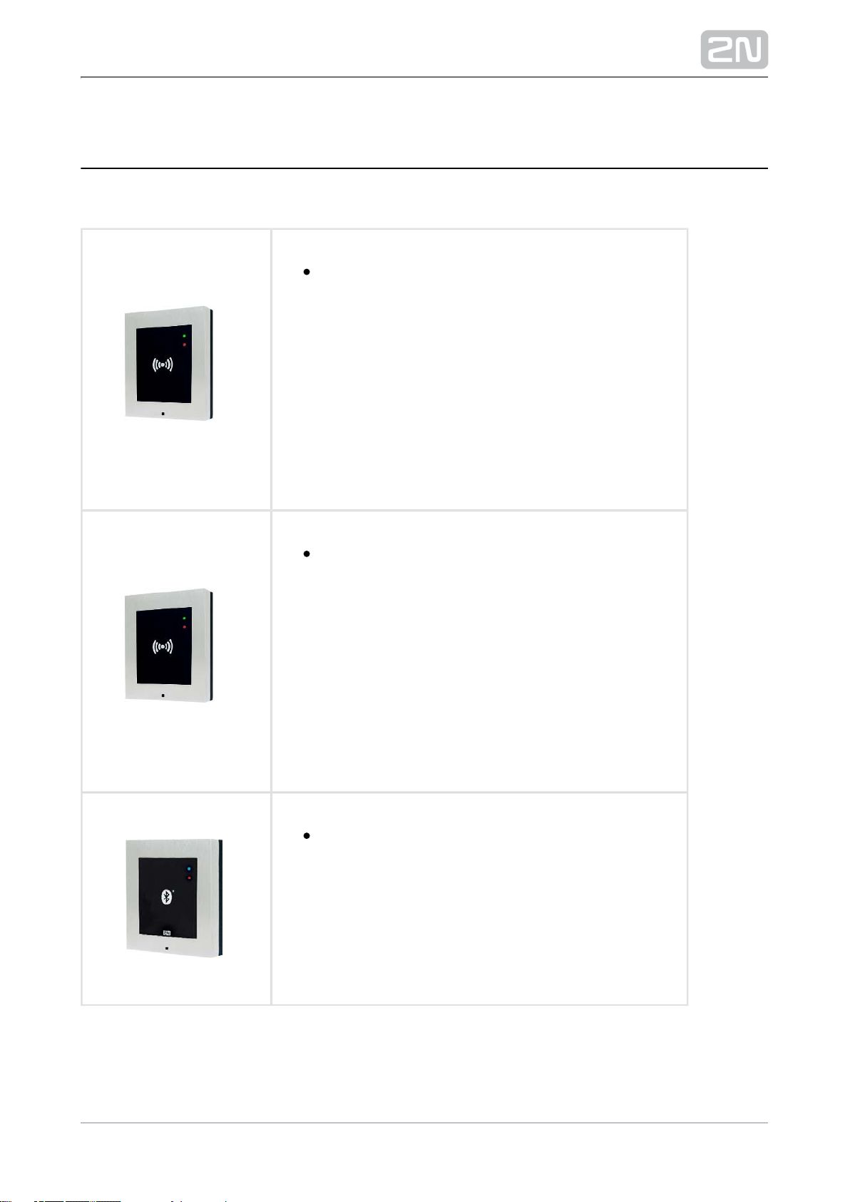
Part No. 916013
2N Access Unit Bluetooth
®
7/98
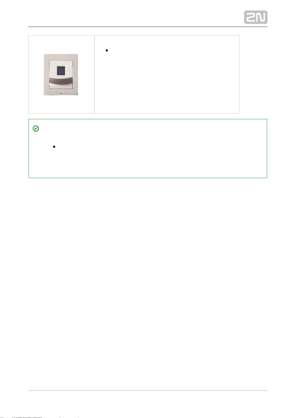
Part No. 916019
2N Access Unit Fingerprint reader
®
Tip
Supported auxiliary modules: 2N Helios IP Verso modules are
®
– RFID card reader (125 kHz; 13.56 MHz), keypad, 5-button supported
module, Wiegand, etc.
8/98
Frames
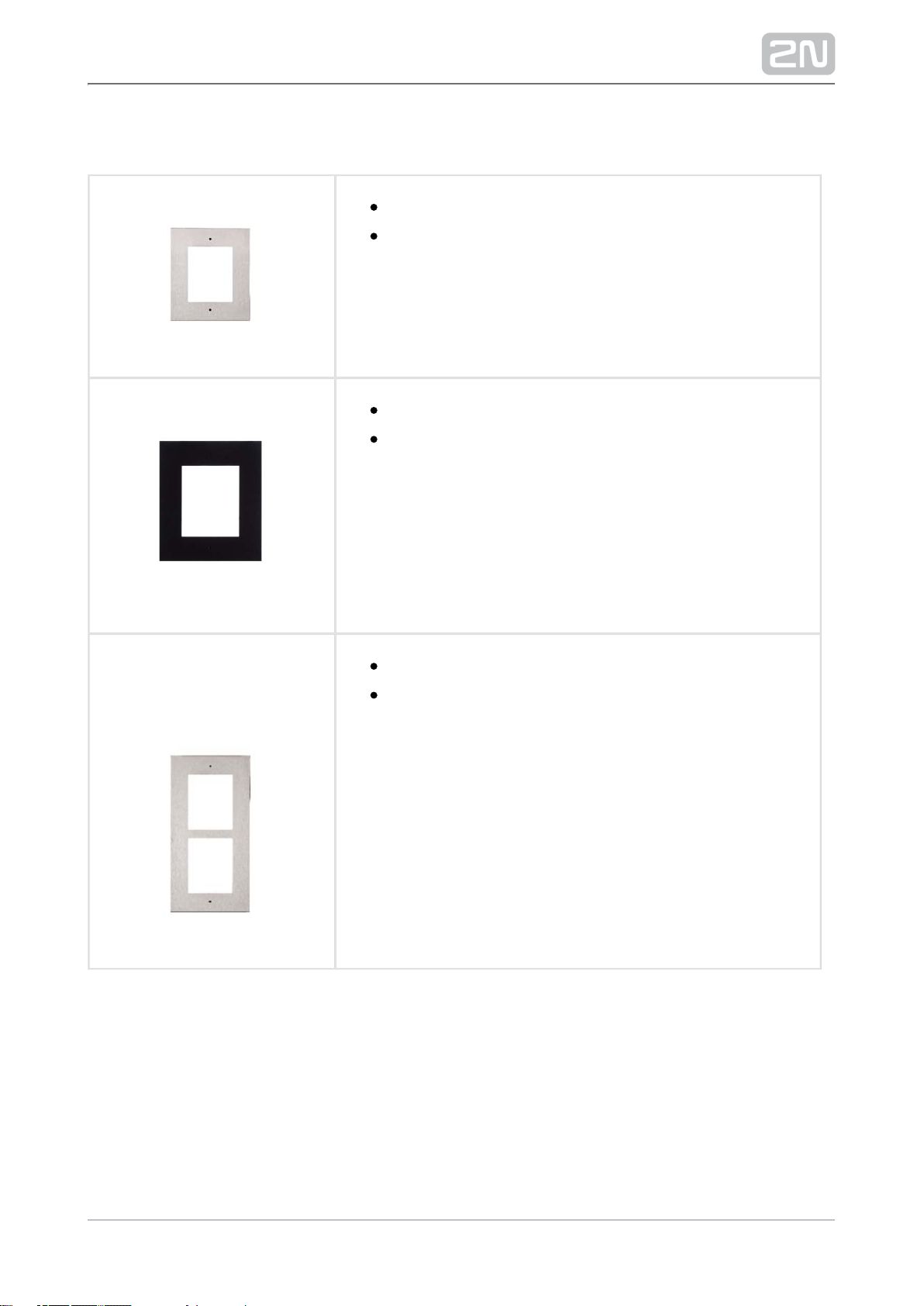
9155011 Part No.
Flush mounting frame, 1-module
Covering frame for the 1-module brick/plasterboard
flush mounting box. This 1-module frame is used for
connection of an OUT card reader or keypad, for
example. Remember to order the frame when you order
a 1-module flush mounting box, Part No. 9155014.
9155011BPart No.
Flush mounting frame, 1-module
Covering frame for the 1-module brick/plasterboard
flush mounting box. This 1-module frame is used for
connection of an OUT card reader or keypad, for
example. Remember to order the frame when you order
a 1-module flush mounting box, Part No. 9155014.
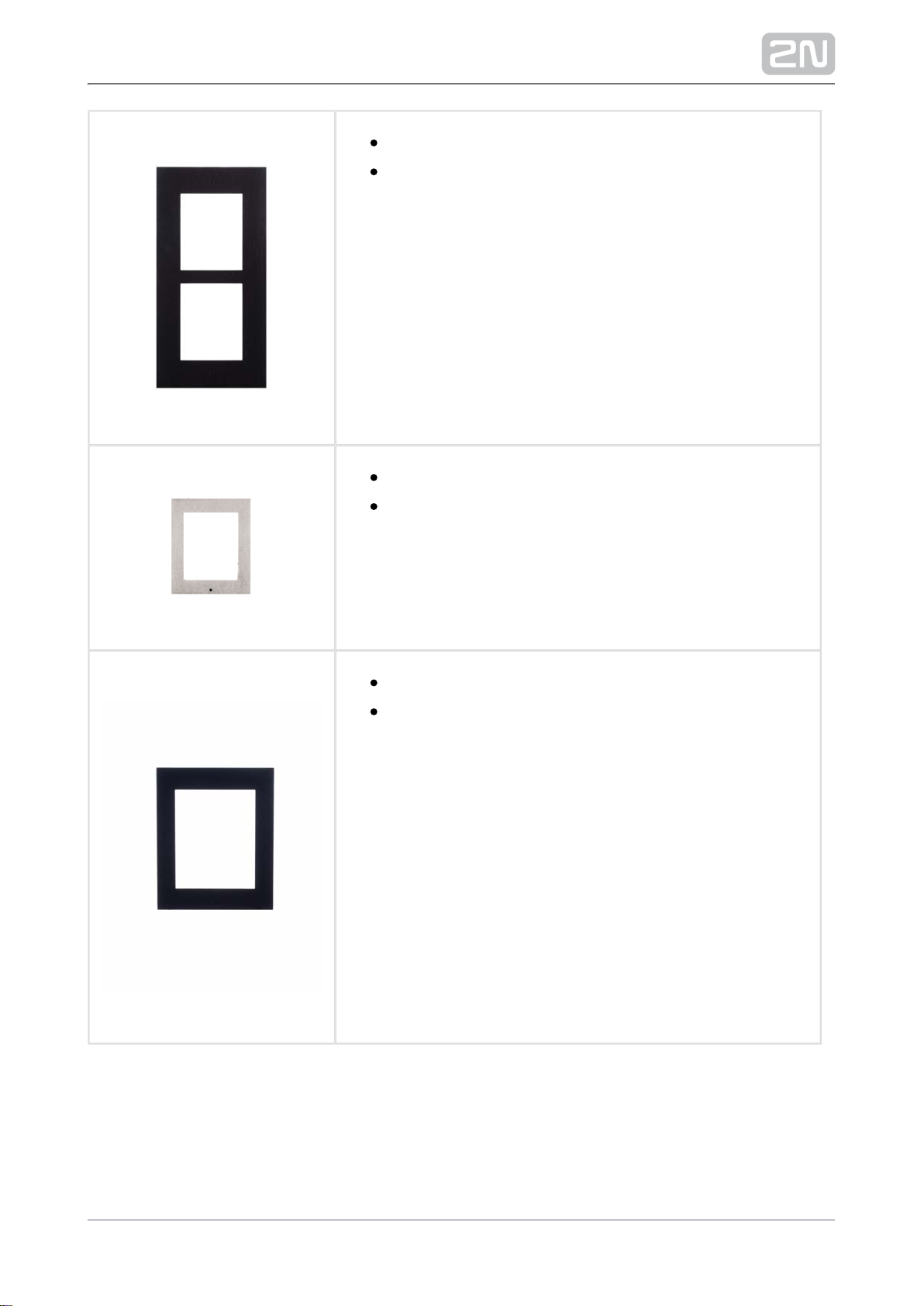
9155012 Part No.
Flush mounting frame, 2-module
Covering frame for the 2-module brick/plasterboard
flush mounting box. Remember to order the frame when
you order a 2-module flush mounting box, Part No.
9155015.
9/98
9155012BPart No.
Flush mounting frame, 2-module
Covering frame for the 2-module brick/plasterboard
flush mounting box. Remember to order the frame when
you order a 2-module flush mounting box, Part No.
9155015.
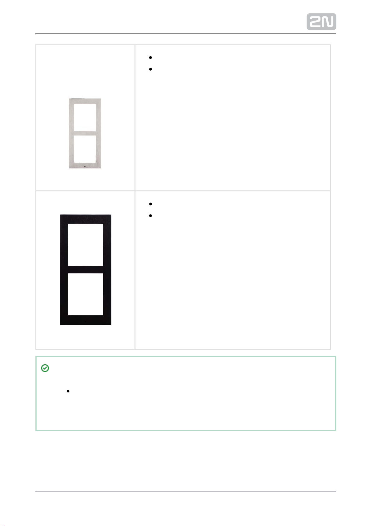
9155021 Part No.
Wall mounting frame, 1-module
Covering frame for wall (surface) mounting.This 1module frame is used for connection of an OUT card
reader or keypad, for example.
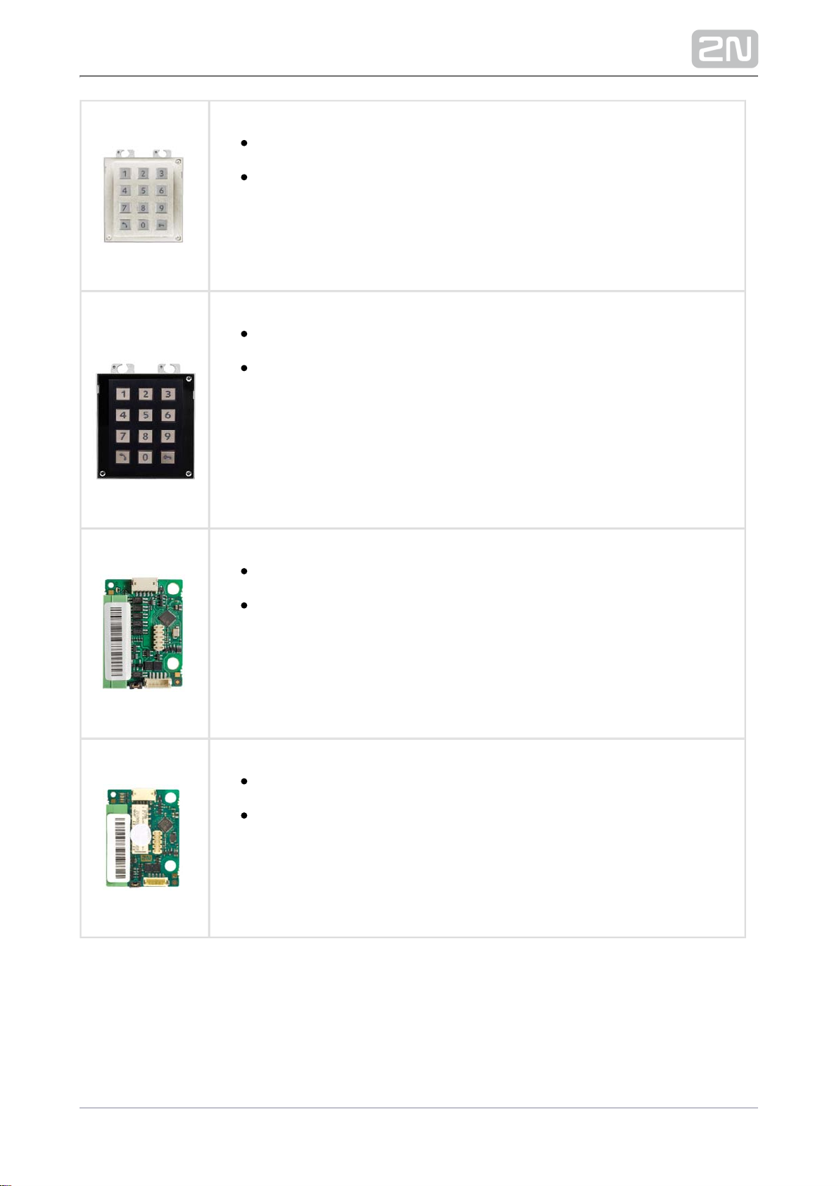
9155021BPart No.
Wall mounting frame, 1-module
Covering frame for wall (surface) mounting.This 1module frame is used for connection of an OUT card
reader or keypad, for example.
10/98
9155022 Part No.
Wall mounting frame, 2-module
Covering frame for wall (surface) mounting.
9155022BPart No.
Wall mounting frame, 2-module
Covering frame for wall (surface) mounting.
Tip
The 1-module frame is used when an auxiliary module from 2N Helios
®
is mounted onto an extended interconnecting cable, for an OUT IP Verso
card reader or keypad, for example.
11/98

Tip
Remember to order the flush mounting frame when you order a brick
/plasterboard flush mounting box:
1-module frame, Part No. – 1-module flush mounting box, 9155011
Part No. .9155014
2-module frame, Part No. – 2-module flush mounting box, 9155012
Part No. .9155015
12/98

Extending Modules
Part No. 916020
RJ-45 adapter
Part No. 9155033
2N Helios IP Verso ®– 13.56 MHz RFID Card Reader
The card reader module works with
2N Access Unit® as an OUT card reader. The module supports cards,
key fobs and/or other 13.56 MHz standard carriers (only card serial
number is read):
ISO/IEC 14443A Mifare Classic 1k & 4k, DESFire EV1, Mini, Plus
S&X, Ultralight, Ultralight C
ISO/IEC 14443B CEPAS, HID iCLASS
JIS X 6319 Felica
Part No. 9155040
Helios IP Verso 2N
®
– 13.56 MHz RFID Card Reader, NFC Preparation
The card reader module works with as an OUT card 2N Access Unit
®
reader. The module supports cards, key fobs and/or other 13.56 MHz
standard carriers (only card serial number is read):
ISO/IEC 14443A Mifare Classic 1k & 4k, DESFire EV1, Mini, Plus
S&X, Ultralight, Ultralight C
ISO/IEC 14443B CEPAS, HID iCLASS
JIS X 6319 Felica
ISO/IEC 18092 SmartPhone with NFC/HCE support, since
Android version 4.3
9155032 Part No.
2N Helios IP Verso ® – 125 kHz RFID Card Reader
The card reader module works with as an OUT card 2N Access Unit
®
reader. The module supports cards, key fobs and/or other 125 kHz
standard carriers: or .EM-41xx HID Proximity
13/98
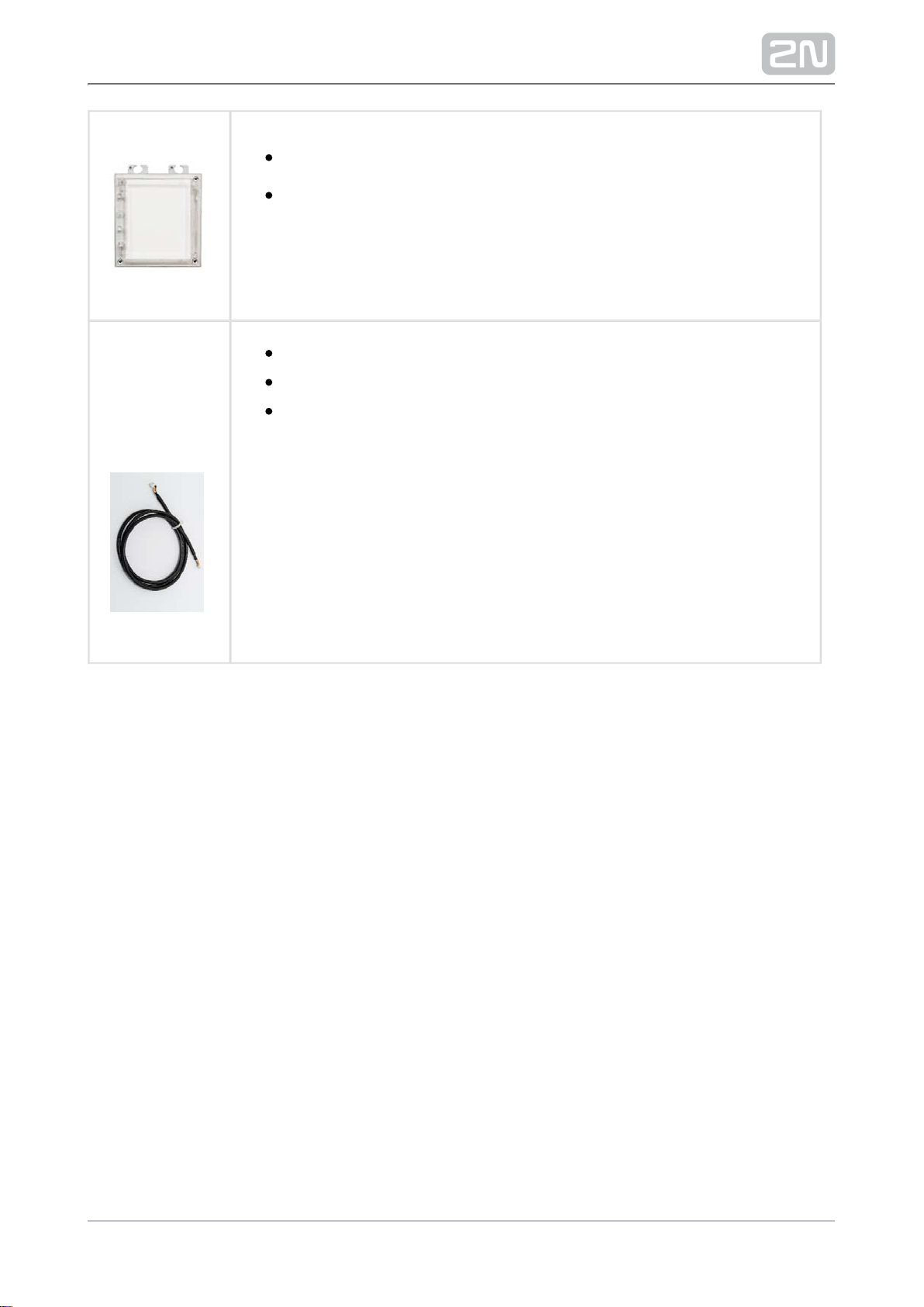
9155031Part No.
2N Helios IP Verso ® – keypad
The numeric keypad module helps enter a numeric entrance code. Use
the keypad for departures or double entrance authentication. The
keypad digits and symbols are backlit.
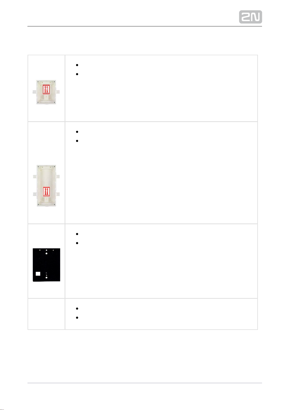
Part No.
9155031B
2N Helios IP Verso ® – keypad
The numeric keypad module helps enter a numeric entrance code. Use
the keypad for departures or double entrance authentication. The
keypad digits and symbols are backlit.
Part No. 9155037
2N Helios IP Verso ® – Wiegand Module
The Wiegand module helps you interconnect your system with other
systems (access, security) via the Wiegand interface. The module is
installed under another module, i.e. cannot be installed directly into the
(must be mounted outside).2N Access Unit
®
Part No. 9155034
2N Helios IP Verso ®– I/O Module
The logic input/output module helps you integrate various sensors and
control doors or other equipment. The module is installed under
another module, i.e. cannot be installed directly into the 2N Access
®
(must be mounted outside).Unit
14/98
9155030Part No.
2N Helios IP Verso ® – Infopanel
The Infopanel module helps you add your company logo, opening
hours and similar information to the access unit. The Infopanel has
software-controlled backlight.
Part Numbers:
1550509
9155054
9155055
1 m Interconnecting Cable
3 m Interconnecting Cable
5 m Interconnecting Cable
15/98
Mounting Accessories
Part No.
9155014
Flush mounting box, 1-module
The box is designed for brick/plasterboard flush mounting of a 1-module
installation. Supplied including accessories for multiple box assemblies.
Part No.
9155015
Flush mounting box, 2-module
The box is designed for brick/plasterboard flush mounting of a 2-module
installation. Supplied including accessories for multiple box assemblies.
Part No.
9155061
Backplate, 1 module
A backplate for glass or uneven surface mounting.
Part No.
9155062
Backplate, 2 modules
A backplate for glass or uneven surface mounting.
16/98

For the choose the appropriate mounting frame and box 2N® Access Unit installation
if necessary. The is designed for outdoor applications and requires 2N® Access Unit
no additional roof.
17/98
Electric Locks
932071EPart No.
BEFO 11211
12 V / 230 mA DC
low consumption
932081EPart No.
BEFO 11221 with momentum pin
12 V / 230 mA DC
low consumption
For opening of the lock a short electrical impuls is sufficient,
which unlocks the lock. Lock is then open until someone closes
the door.
932091EPart No.
BEFO 11211MB with mechanical blocking
12 V / 230 mA DC
low consumption
Enables mechanically close or open the lock. When opened,
the lock is open all the time. When closed, it behaves as
standart electrical lock.
Part No. 932061E
211211 door signalling, low consumption
12 V / 230 mA
A regular lock with a built-in contact to indicate whether the
door is open or closed.
18/98
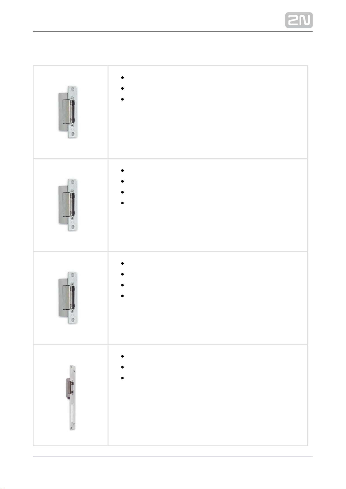
Part No. 932072E
31211 fail-safe
12 V / 170 mA DC
The failsafe lock is closed when electricity is switched on.
When electricity is interrupted, the lock is opened.
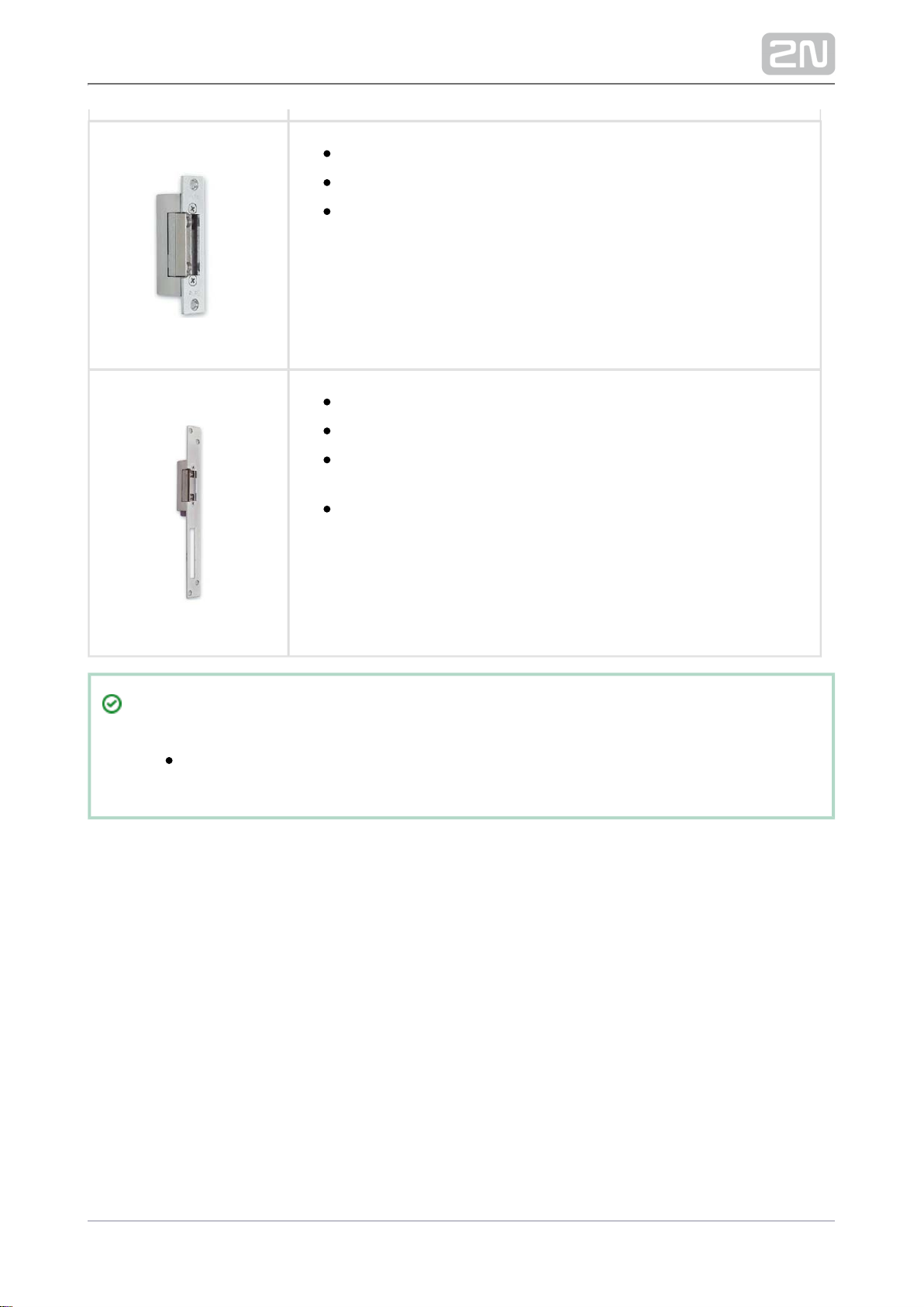
Part No. 932062E
321211 fail-safe, door signalling
12 V / 170 mA
The failsafe lock is closed when electricity is switched on.
When electricity is interrupted, the lock is opened.
It contains a built-in contact to indicate whether the door is
open or closed.
Tip
FAQ:Electric locks – Differences between locks for 2N Helios IP
®
19/98
Power Supply
Part Numbers:
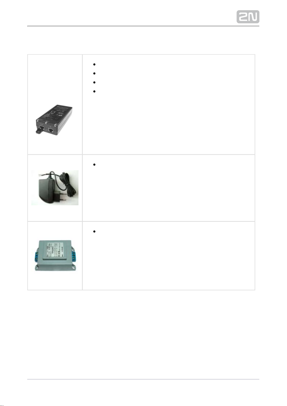
91378100
91378100E
91378100US
PoE injector – without cable
PoE injetor – with EU cable
PoE injector – with US cable
For power supply of intercom via ethernet cable when PoE switch
is not available.
91341481EPart No.
Stabilised 12 V / 2 A power supply needs to be used when no PoE
is available.
932928Part No.
For external power supply of the lock with 12 V AC voltage.
20/98

Additional Modules
9159010 Part No.
Security relay
A simple, security enhancing add-on. Prevents lock tampering.
Installed between the intercom, from which it is also supplied,
and the lock to be controlled.
Part No. 9159013
Departure button
Connects the logic input for door unlocking from inside the
building.
Part No. 9159012
Magnetic door contact
A door installation set for door opening status identification.
Used for door protection, open door or violent door opening
detection.
9134173 Part No.
13.56 MHz Mifare RFID card
21/98

Part No. 9134174
13.56 MHz Mifare RFID key fob
9134165E Part No.
125 kHz RFID card of type EM4100
9134166E Part No.
125 kH RFID key fob
9137420E Part No.
External RFID card reader for connection to PC using a USB
interface.
Suitable for system administration and adding of 125 kHz
EM41xx cards using a web interface or the 2N Access
®
Commander .
Part No. 9137421E
13.56 MHz and 125 kHz USB RFID card reader
External RFID card reader for connection to PC using a USB
interface. Suitable for system administration and adding of
13.56 MHz and 125 kHz cards using a web interface or the
.2N Access Commander
®
22/98
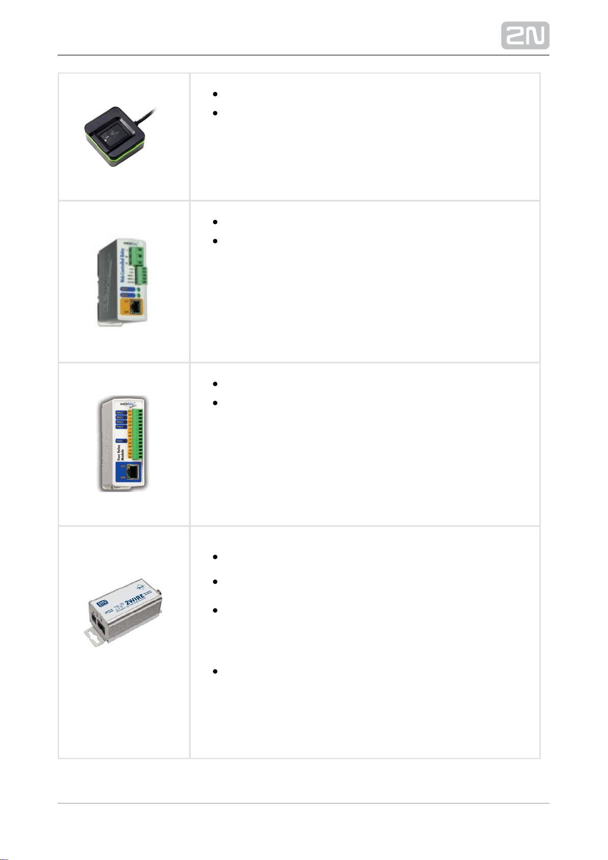
Part No. 9137423E
External Fingerprint reader ( USB interface )
Intended for administration and adding user fingerprints.
9137410E Part No.
External IP relay – 1 output
A stand-alone IP device, which can be controlled from an IP
intercom via HTTP commands. Helps control a device remotely.
9137411E Part No.
External IP relay – 4 outputs, PoE
A stand-alone IP device, which can be controlled from an IP
intercom via HTTP commands. Helps control a device remotely.
Part No. 9159014EU/US
/UK
2N 2Wire
®
(set of 2 adapters plus EU/US/UK power supply)
Converter helps you connect any IP device to your 2N 2Wire
®
existing two-wire cabling from the original door bell/phone
without reconfiguring. All you have to do is have one
2N 2Wire ® unit at each end of the cable and connect one of
them at least to the power supply.
The then provides supply not only to the 2N 2Wire unit
®
PoE
other converter, but also to all the IP terminal equipment
connected.
23/98
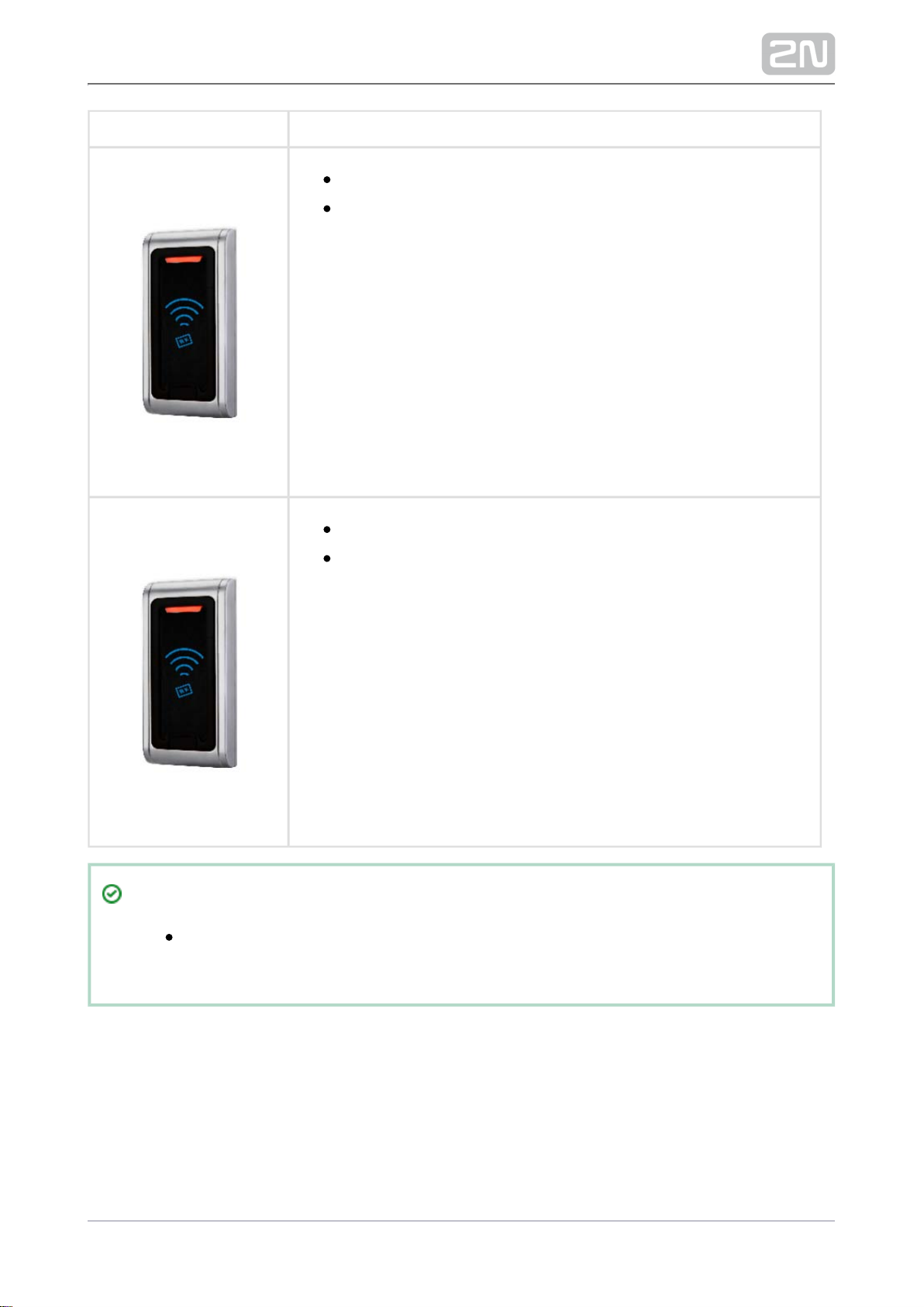
Part No. 9159030
External 125 kHz RFID card reader
Secondary reader for connection to an internal reader. Allows
for control of card entry from both sides of the door. IP67
cover, also suitable for exteriors. Reads EM4100 and EM4102
cards.
Part No. 9159031
External 13.56MHz Mifare RFID card reader, Wiegand
Secondary reader for connection to an internal reader. Allows
for control of card entry from both sides of the door. IP68
cover, also suitable for exteriors. Reads Mifare cards.
Tip
Refer to the local 2N distributor for more accessories and
recommendations please.
24/98

1.2 Terms and Symbols
The following symbols and pictograms are used in the manual:
Safety
Always abide by this information to prevent persons from injury.
Warning
Always abide by this information to prevent damage to the device.
Caution
Important information for system functionality.
Tip
Useful information for quick and efficient functionality.
Note
Routines or advice for efficient use of the device.
25/98

2. Description and Installation
Here is what you can find in this section:
2.1 Before You Start
2.2 Mechanical Installation
2.3 Electric Installation
2.4 Extending Module Connection
2.5 Mounting Completion
26/98

Product Completeness Check
Check your package for completeness before installation.2N Access Unit
®
1x 2N Access Unit
®
1x Hex key
Brief manual
27/98
2.2 Mechanical Installation
Mounting Types Overview
Refer to the table below for a list of mounting types and necessary components. You
can assemble multiple units in all the mounting types.
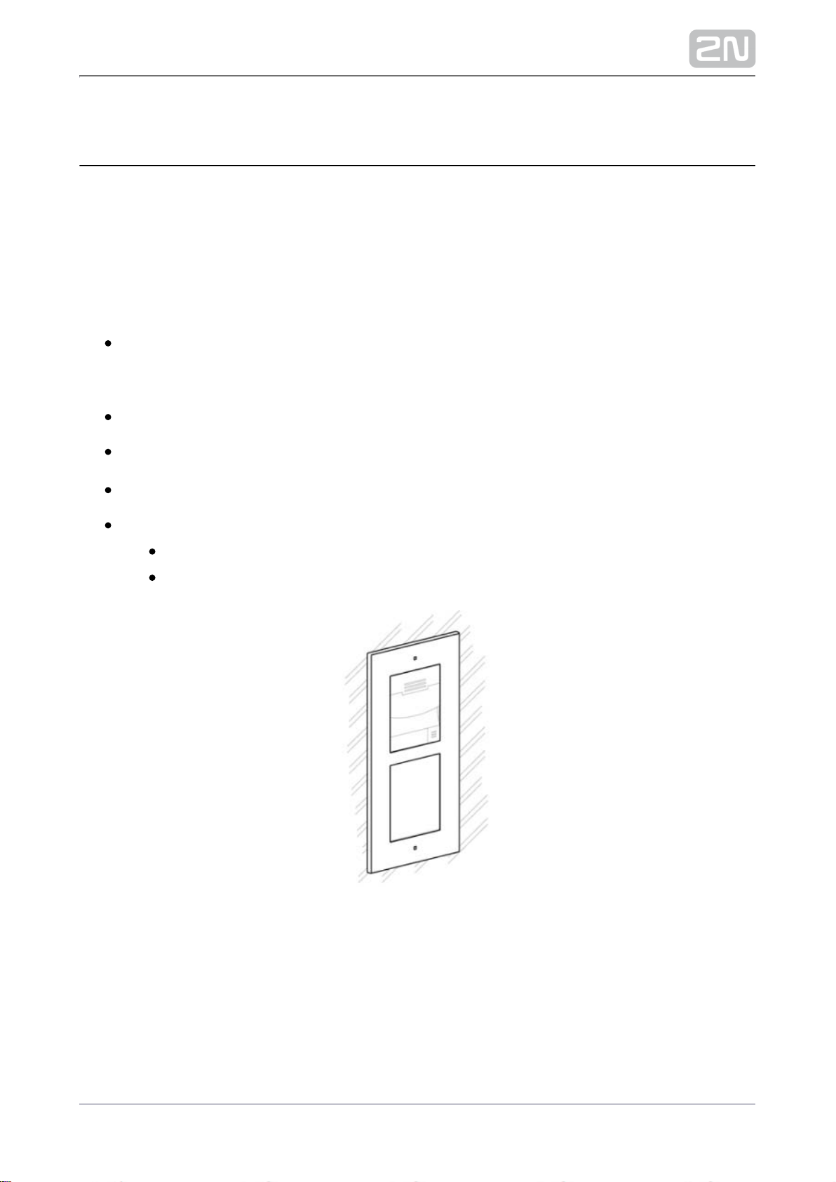
Flush mounting – classic bricks
incl. hollow bricks, thermally insulated walls, etc.
What you need for mounting:
a properly cut hole as instructed in the box package
plaster, mounting glue, mounting foam or mortar as necessary
2N Access Unit
®
flush mounting box and frame
1 module: box Part No. , frame part No. 9155014 9155011
2 modules: box Part No. , frame part No. 9155015 9155012
28/98
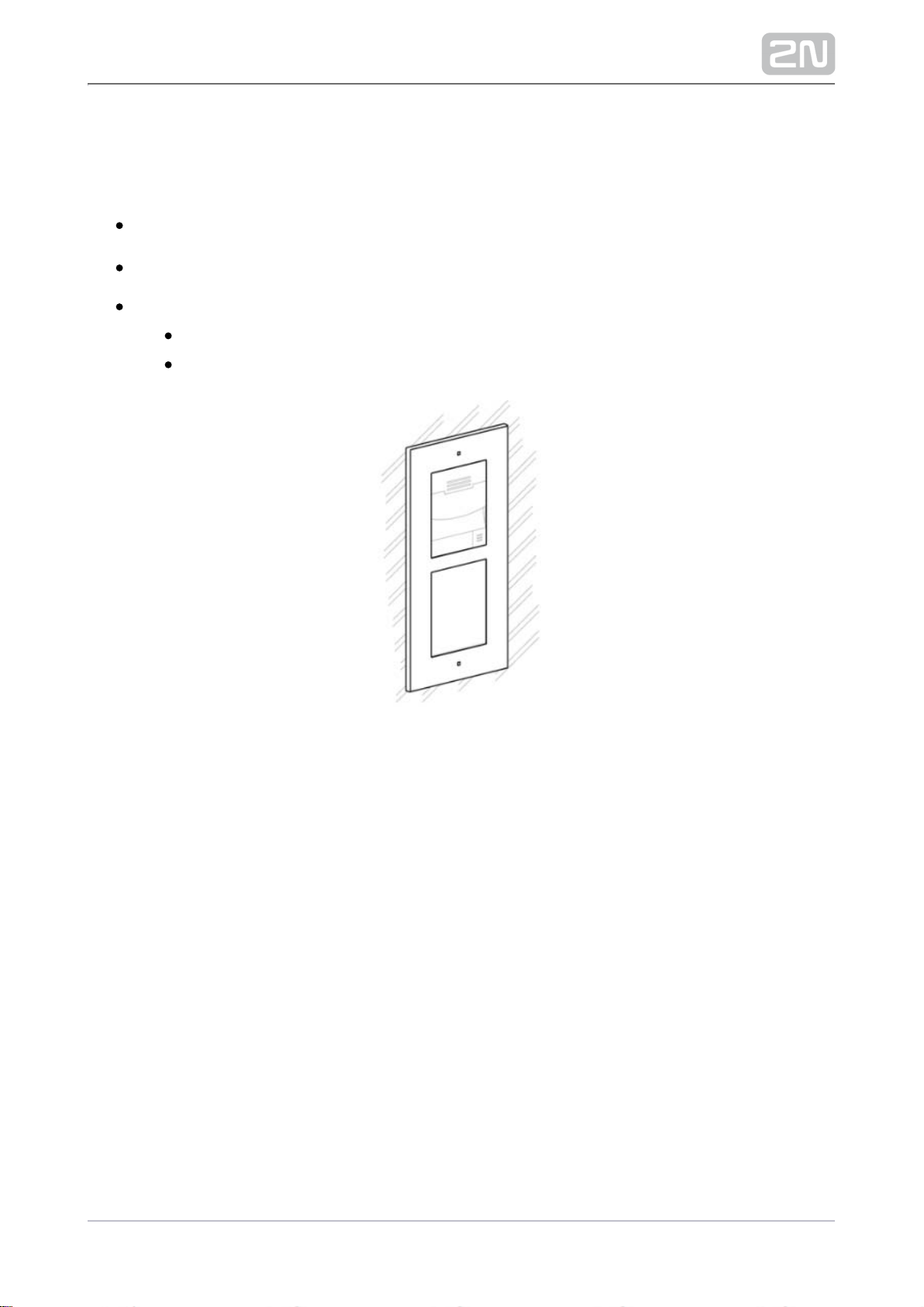
Flush mounting – plasterboard
What you need for mounting:
a properly cut hole as instructed in the box package
2N Access Unit
®
flush mounting box and frame
1 module: box Part No. , frame part No. 9155014 9155011
2 modules: box Part No. , frame part No. 9155015 9155012
29/98
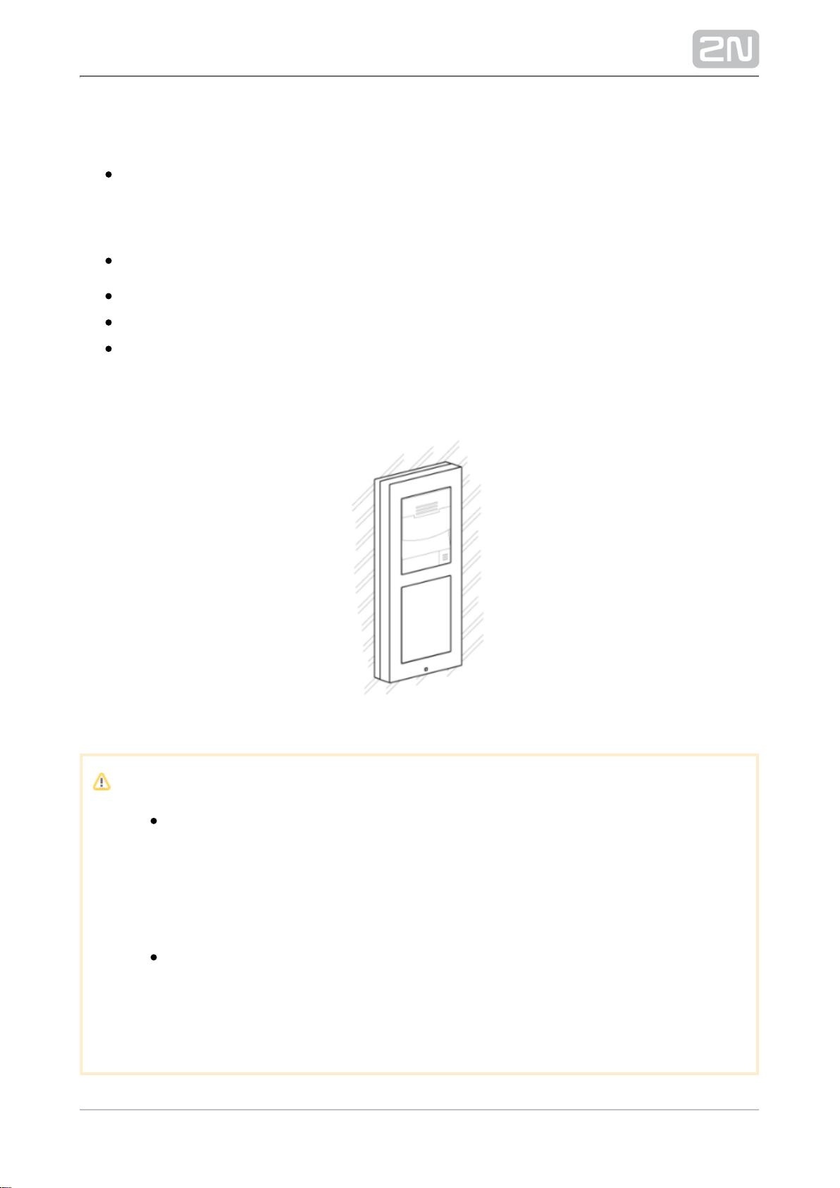
Wall (surface) mounting
(concrete and steel structures, entry barrier columns, interiors, etc.)
What you need for mounting:
2N Access Unit
®
a proper frame
1 module: frame Part No. 9155021
2 modules: frame Part No. 9155022
For uneven surfaces use a backplate for the required count of modules, Part Nos.
–9155061 9155062
Caution
The warranty does not apply to the product defects and failures arisen
as a result of improper mounting (in contradiction herewith). The
manufacturer is neither liable for damage caused by theft within an area
that is accessible after the attached electric lock is switched on. The
product is not designed as a burglar protection device except when
used in combination with a standard lock, which has the security
function.
When the proper mounting instructions are not met, water might get in
and destroy the electronics. It is because the intercom circuits are under
continuous voltage and water infiltration causes an electro-chemical
reaction. The manufacturer’s warranty shall be void for products
damaged in this way!
30/98

General Mounting Principles
Tip
Select flush mounting where possible to make your product elegant
looking, more vandal resistant and more secure.
You are advised to buy the flush mounting box in advance and
commission a building company to do the masonry for you, for example.
The mounting box also helps you put your intercom exactly in the
vertical position.
31/98

Caution
Make sure that the diameter of the dowel holes is accurate to avoid
falling out of the dowels! Use the mounting glue to secure the dowels if
necessary.
Make sure that the depth of the dowel holes is accurate!
Do not use low-quality dowels to avoid falling out of the dowels of the
wall!
Having removed the front panel, make sure that no dirt gets inside the
product (especially onto the sealing surface).
Never turn an assembly of devices after mounting. 2N Access Unit
®
Make sure that the flush mounting boxes have been installed accurately.
Check the plasterboard wall and room interior pressure values. If the
difference between the values is too great (as a result, e.g., of
overpressure ventilation), separate the intercom using, for example, the
mounting box enclosed and seal the cable passage.
Surface mounting may cause problems on places exposed to potential
vandalism (such as public garages, etc.). In this case, use steel anchoring
elements instead of the dowels and screws included in the delivery.
The wall mounting surface must be flat with the maximum inequality of
0.5 mm (e.g. prefabricated boards, glass, cut stone, etc.). If the surface is
uneven, use flush mounting and a backplate, – , Part Nos. 9155061 9155062
or equalise the wall surface.
32/98

Risk of personal injury
Eliminate the risk of personal injury! Wall mounting is not recommended
for narrow passages or places where people’s attention is distracted by
something else. The manufacturer shall not be liable for injuries in such
cases!
Module Installation
2.2.1 One Module Box
2.2.2 Two Module Box
2.2.3 Module dimensions
33/98

2.2.1 One Module Box
Flush mounting – classic bricks
34/98

35/98

Flush mounting – plasterboard
36/98

37/98

38/98

Module flush mounting
39/98

40/98

41/98

42/98

43/98

Wall (surface) mounting
44/98

45/98

46/98

47/98

48/98

2.2.2 Two Module Box
Flush mounting – classic bricks
49/98

50/98

51/98

52/98

Flush mounting – plasterboard
53/98

54/98

55/98

Module flush mounting
56/98

57/98

58/98

59/98

60/98

Wall (surface) mounting
61/98

62/98

63/98

64/98

65/98

2.2.3 Module dimensions
Frames
9155011 – Flush mounting frame, 1 module
9155012 – Flush mounting frame, 2 modules
9155021 – Surface mounting frame, 1 module
9155022 – Surface mounting frame, 2 modules
Backplates
9155061 – 1 module
9155062 – 2 modules
66/98

1.
2.
1.
2.
3.
4.
2.3 Electric Installation
This subsection describes how to install the modules and connect the 2N Access Unit
®
to the power supply and LAN and how to connect other elements.
Version A – Stand-alone Access Unit
Place the on the flush mounting box / pre-drilled holes with 2N Access Unit
®
dowels and pull the cables through the bottom holes. Pull the Ethernet cable
through the bottom hole to the left if necessary.
Insert the metal fitting elements up and down and screw the access unit tight.
You can level the unit slightly in this mounting type.
Version B – Access Unit with an additional module
Unscrew the upper part of the additional base – keypad, RFID reader, etc.
Use a flat screwdriver to take the upper part out.
Slide the additional module to the access unit. Secure its position with small side
wedges and screws.
Place the assembled modules on the flush mounting box / predrilled holes with
dowels and pull the cables through the access unit bottom holes. Feed the
Ethernet cable without the connector from the additional module to the access
unit base if necessary.
2N ® Access Unit
Power Supply Connection
2N Access Unit ®can be powered either from an external 12 V / 2 A DC source or
directly from the LAN equipped with PoE 802.3af supporting network elements.
External power supply
For reliability reasons, use a 12 V ±15 % SELV supply dimensioned to the current
consumption as required for feeding of the access unit and connected modules.
67/98

Current consumption
[A]
Part No. Available power output
[W]
2 91341481E 24
3 36
PoE power supply
2N Access Unit ®is compatible with the PoE 802.3af (Class 0–12.95 W) technology and
can be fed directly from the LAN via the compatible network elements. If your LAN
does not support this technology, insert a PoE injector, Part No. 91378100, between
and the nearest network element. This power supply provides2N Access Unit
®
with 12 W for feeding of itself and the connected modules.2N Access Unit
®
Combined power supply
2N Access Unit ®can be fed from an external power supply and PoE at the same time.
In this configuration, the maximum power for the connected modules is available.
LAN Connection
2N Access Unit ®is connected to the Local Area Network (LAN) via the UTP/STP
cable (Cat 5e or higher) terminated with a terminal board as shown in the figure
below. As the device is equipped with the Auto-MDIX function, either the straight or
crossed cable can be used.
Caution
We recommend the use of a LAN surge protection.
68/98

Caution
There may be connectivity problems in version 586v2 if a 2N Access Unit
®
cable longer than 30 m is used for LAN connection. If this happens, we
recommend you to:
integrate another network element (switch) to shorten the jump
feed the device from an external 12 V supply
change the PoE phantom supply (typically TP-LINK) to spare-pair supply
– Phihong injector, Part No. 91378100
change the Ethernet bitrate to Half Duplex – 10 mbps
UTP Cable Connection to Access Unit Terminal Board
Legend to the figure
PoE,
RD, TD
LAN (PoE according to 802.1af) terminals
IN1,
IN2,
IN3
IN1, IN2 and IN3 terminals used as an input in the passive/active mode (−30 V to +30 V
DC) for departure button, open door sensor, ESS etc. connection
OFF = open OR U > 1.5 V
IN
ON = closed contact OR U < 1.5 V
IN
69/98

OUT1
OUT1 active output terminals for connection of or 2N Helios IP Security Relay
®
electric lock: 8 up to 12 V DC depending on power supply (PoE: 10 V; adapter: power
supply voltage minus 2 V), up to 400 mA
RELAY1 RELAY1 terminals with accessible 30 V / 1 A AC/DC NO/NC contact
12V/2A
External supply terminals for – 12 V / 2 A DC (3 A for multiple 2N Access Unit
®
modules)
RESET RESET / FACTORY RESET button
RJ-45 RJ-45 adapter connector – no need to use the PoE, RD and TD terminals for this
connector
Tip
Wiring diagram of IN1, IN2 and IN3 terminals in active mode
Wiring diagram of IN1, IN2 and IN3 terminals in passive mode
Device Restart
Press the RESET button (between the LED indicators in the right-hand upper part)
shortly to restart the device.
70/98

Factory Reset
is equipped with a button, which is 2N Access Unit
®
RESET located between the LED
(LED1 and LED2 as shown in the figure below) indicators in the right-hand upper part
. in version . of the unit The button is located in the middle of the lower part 586v4
Press the button shortly (< 1 s) to restart the system without changing configuration.
2N Access Unit ®Connectors, PCB Version 586v2
71/98

2N Access Unit ®Connectors, PCB Version 586v4
To follow the instructions below:get the current IP address,
Press and hold the RESET button.
Wait for approx. 20 s until the red and green LEDs in the right-hand bottom part
(LED8 and LED9 in the figure above).of the motherboard shine simultaneously
Release the RESET button.
The device announces the current IP address via the speaker automatically.
To switch on the (DHCP OFF), follow the instructions below:static IP address mode
Press and hold the RESET button.
Wait untilthe red and green LEDs in the right-hand bottom part of the
(approx. 20 s).motherboard shine simultaneously
Wait until the red LED goes off (approx. 5 s).
72/98

Release the RESET button.
The following network parameters will be set after restart:
IP address: 192.168.1.100
Network mask: 255.255.255.0
Default gateway: 192.168.1.1
To switch on the (DHCP ON), follow the instructions below:dynamic IP address mode
Press the RESET button.
Wait untilthe red and green LEDs in the right-hand bottom part of the
(approx. 20 s).motherboard shine simultaneously
Wait until the red LED goes off (approx. 5 s).
Wait until the green LED goes off and the red LED comes on again (another 5 s).
Release the RESET button.
To reset follow the instructions below:the factory values,
Press the RESET button.
Wait untilthe red and green LEDs in the right-hand bottom part of the
(approx. 20 s).motherboard shine simultaneously
Wait until the red LED goes off (approx. 5 s).
Wait until the green LED goes off and the red LED comes on again (another 5 s).
Wait until the red LED goes off (approx. 5 s).
Release the RESET button.
73/98

Caution
In case of resetting the factory default settings on a device with a
version of firmware 2.18 or higher it is necessary to reprogram the
using the instructions from section .2N Helios IP Security Relay
®
2.4
Available Switches
Location Name Description
Basic
unit
Relay 1 Passive switch: NO/NC contact, up to 30 V / 1 A AC/DC
Output 1Active switch output: 8 up to 12 V DC depending on power supply (PoE: 10
V; adapter: power supply voltage minus 2 V), up to 400 mA
Warning
When you connect a device containing a coil, such as a relay or an
electromagnetic lock, it is necessary to protect the intercom output
againstvoltage peak while switching off the induction load. For this way of
protection we recommend a 1 A / 1000 V diode (e.g., 1N4007, 1N5407,
1N5408) connected antiparallel to the device.
74/98

2.4 Extending Module Connection
2N Access Unit ®allows to connect following extending modules:
Infopanel
Keypad
125 kHz RFID card reader
13.56 MHz RFID card reader
Bluetooth module
Fingerprint reader
I/O module
Electronic buttons
Wiegand module
Security relay
Module Bus Interconnection
All the modules that can be connected to are interconnected via a 2N Access Unit
®
bus. The bus starts on the basic unit and goes over all the modules. The order of
modules on the bus is irrelevant. And it also irrelevant which bus connector on the
module is used as the input and which is used as the output.
The modules include a 220 mm long bus interconnecting cable; Part No. 9155037
Wiegand modules and I/O modules include an 80 mm long bus Part No. 9155034
cable. These two modules can be hidden inside one of the modules described below
(Infopanel, Keypad, RFID card reader, Bluetooth) and/or placed freely behind a
standalone access unit (in a mounting box, e.g.).
You can order a separate bus cable ( , , ) of the Part Nos. 9155050 9155054 9155055
length of 1 m, 3 m or 5 m for remote module installation. Typically, it helps install an
RFID card reader on the opposite side of the wall on which is 2N Access Unit
®
installed. This long cable can only be used once on the bus.
Module Power Supply
All the modules connected to , except for the Tamper Switch, are 2N Access Unit
®
powered from the bus. The available bus power output depends on the power supply
type. The basic unit can use a 2 A power supply to increase the bus power available to
the modules connected.
75/98

Power supply Specification Available power output
External supply 12 V ±15% / 2 A (3 A) 24 W (36 W)
PoE 802.3af (Class 0–12.95 W) 12 W
Combined External supply + PoE 30 W (42 W)
The count of modules on the bus is limited by the available power supply output. The
maximum count of the modules on the bus is 30.
Basic unit
(571v3)
Consumption [W]
(Maximum value)
At relax 1.2
OUT 1 4.8
Total 6
Module Idle consumption
[W]
(Minimum value)
Full load [ ]W
(Maximum
value)
[Special elements W
]
Basic unit (586v3) 1.2 6
Infopanel (580v2) 0.17 0.64
Keypad (579v2) 0.20 1.55
125 kHz RFID card reader (584v2)
13.56 MHz RFID card reader
(583v2)
0.42 0.89
Bluetooth module (2271v2) 0.15 0.3
I/O module (577v2) 0.35 0.66 Closed relay 0.13
76/98

Module Idle consumption
[W]
(Minimum value)
Full load [ ]W
(Maximum
value)
[Special elements W
]
Wiegand module (581v1)
Specimen configuration consumption computation:
Module Minimum consumption
[W]
Maximum consumption
[W]
Basic unit 1.2 6
13.56 MHz RFID card reader (583v2) 0.42 0.89
I/O module (577v2) 0.35 0.66
Tamper switch 0 0
Wiegand module (581v1) x x
Total 2.07 7.55
It is obvious from the specimen configuration that all the modules have sufficient
outputs when an external power supply is used. When a PoE supply is used, the power
output is insufficient for all the modules, which results in automatic decrease in
backlight level, active output current supply, volume and LED intensity.
Some modules need a specific power output for their specific activities: the I/O
module, e.g., requires 0.13 W for relay closing (not included in the minimum
consumption).
Keypad Module
The Keypad module ( ) is used for a numeric access to the system.Part No. 9155031
The module contains two bus connectors for .2N Access Unit
®
These two connectors are fully interchangeable and can be used either as inputs
from the basic unit or outputs to other modules.
If this module is the last one on the bus, one of the connectors remains
unconnected.
The module package includes a 220 mm long interconnecting cable.
77/98

125 kHz RFID Card Reader Module
The 125kHz RFID card reader module ( ) is used for reading RFID Part No. 9155032
card Ids in the 125 kHz band.
The module contains two bus connectors for .2N Access Unit
®
These two connectors are fully interchangeable and can be used either as inputs
from the basic unit or outputs to other modules.
If this module is the last one on the bus, one of the connectors remains
unconnected.
The module package includes a 220 mm long interconnecting cable.
The following RFID cards can be read:
EM4100, EM4102, HID Proximity
13.56 MHz RFID Card Reader Module
The 13.56 MHz RFID card reader module ( ) is used for reading RFID Part No. 9155033
card Ids in the 13.56 MHz band.
The module contains two bus connectors for .2N Access Unit
®
These two connectors are fully interchangeable and can be used either as inputs
from the basic unit or outputs to other modules.
If this module is the last one on the bus, one of the connectors remains
unconnected.
The module package includes a 220 mm long interconnecting cable.
The following RFID cards can be read (only card serial number is read):
ISO 14443A
Mifare Classic 1k & 4k, DESFire EV1, Mini, Plus S&X, Ultralight, Ultralight C
ISO 14443B
CEPAS, HID iCLASS
JIS X 6319
Felica
78/98

Bluetooth Module
The Bluetooth module ( ) helps authenticate and subsequently Part No. 9155046
open doors using Android and iOS based smartphones via the Bluetooth
protocol 4.0 as RFID card replacement. Install the application 2N ®Mobile Key
and to m from Google Play Appstore ake authentication work properly. The
application requires phones with Android OS 4.4 and higher and iOS 9 and
higher.
The module contains two bus connectors.2N ®Access Unit
The two connectors are fully interchangeable and can be used both as inputs
from the main unit or outputs to other modules.
If this module is the last one on the bus, one of the connectors remains
unconnected.
The package includes a 220 mm long interconnecting cable.
The module uses the 2.4 GHz frequency.
IDs from the following smart phones can be read:
Android 4.4 and higher
iPhone 4S with iOS 8 and higher and higher
Fingerprint reader
The is used for automated verification of human fingers for access Fingerprint reader
control and intercom control.
The module contains two bus connectors.2N ®Access Unit
These two connectors are fully interchangeable and can be used both as inputs
from the main unit and outputs to other modules.
If this module is the last one on the bus, one of the connectors remains
unconnected.
The module package includes a 220 mm long interconnecting cable.
Important module properties:
FBI PIV and Mobile ID certification – FAP20
Durable glass touch surface
Rejects spoof fingerprints
-20 to 55 ºC operating temperature range,
0–90% relative humidity, noncondensing
79/98

I/O Module
The I/O module ( ) is used for extending of the number of inputs and Part No. 9155034
outputs.
The module contains two bus connectors for .2N Access Unit
®
These two connectors are fully interchangeable and can be used either as inputs
from the basic unit or outputs to other modules.
If this module is the last one on the bus, one of the connectors remains
unconnected.
The module package includes an 80 mm long interconnecting cable.
The inputs / outputs are addressed as follows:<module_name>.<input
, e.g. module5.relay1. Configure the module name in the Module /output_name>
name parameter in the Hardware / Extenders menu.
RELAY1 RELAY1 terminals with accessible 30 V / 1 A AC/DC NO/NC contact
RELAY2 RELAY2 terminals with accessible 30 V / 1 A AC/DC NO/NC contact
IN1 IN1 terminals for input in passive/ active mode (−30 V to +30 V DC)
OFF = open or U > 1.5 V
IN
ON = short-circuit or U < 1.5 V
IN
80/98

IN2 IN2 terminals for input in passive/active mode (−30 V to +30 V DC)
OFF = open or U > 1.5 V
IN
ON = short-circuit or U < 1.5 V
IN
TAMPER Tamper switch input, Part No. 9155038
Infopanel Module
The Infopanel module ( ) is used for inserting and backlighting of Part No. 9155030
printed information.
The module contains two bus connectors for .2N Access Unit
®
These two connectors are fully interchangeable and can be used either as inputs
from the basic unit or outputs to other modules.
If this module is the last one on the bus, one of the connectors remains
unconnected.
The module package includes a 220 mm long interconnecting cable.
Name tag dimensions: 69.2 (W) x 86.7 (H) mm (dimensional tolerance: +0; -0.5
mm).
For the printing template refer to www.2n.cz
Wiegand Module
The Wiegand module ( ) helps connect an external Wiegand device Part No. 9155037
(RFID card reader, fingerprint or other biometric data reader) and/or connect 2N
®
to an external security exchange. All the inputs and outputs are Access Unit
galvanically isolated from with the insulation strength of 500 V DC.2N Access Unit
®
The module contains two bus connectors for .2N Access Unit
®
These two connectors are fully interchangeable and can be used either as inputs
from the basic unit or outputs to other modules.
If this module is the last one on the bus, one of the connectors remains
unconnected.
The module package includes an 80 mm long interconnecting cable.
Configure the module name in the Module name parameter in the Hardware /
Extenders menu.
The LED IN input is addressed as follows: , e.g. <module_name>.<input1>
module2.input1.
81/98

The Tamper input is addressed as follows: , e.g. <module_name>.<tamper>
module2.tamper.
The LED OUT (negated)output is addressed as follows: <module_name>.
, e.g. module2.output1.<output1>
Reader W0 W1 GNDIN, IN, 1 Isolated 2-wire WIEGAND IN
LEDOUT Isolated open LED OUT switched against GND (up to 24 V 1
/ 50 mA)
Control
Panel
+UIN +U (5 to 15 V DC) WIEGAND OUT power supply input
W0 W1 GNDOUT, OUT,
2
Isolated 2-wire WIEGAND OUT
LEDIN (negated) Isolated input for open LED IN, input activated by GND
2
LEDIN Isolated input for open LED IN, input activated by +U
G active supply LED indicator +U WIEGAND OUTIN
TAMPER Tamper switch input, Part No. 9155038
82/98

Security Relay
The ( ) is used for enhancing security between the Security relay Part No. 9159010
access unit and the connected electric lock. It significantly enhances security of the
connected electric lock as it prevents unlocking by forced opening of the 2N Access
®
.Module
Function:
The is a device installed between the access unit (outside the secured Security relay
area) and an electric lock (inside the secured area). The includes a relay Security relay
that can only be activated if the valid opening code is received from the access unit.
Specifications:
Passive switch: NO and NC contacts, up to 30 V / 1 A AC / DC
Active switch output: 9 to 13 V DC according to power source (PoE: 9 V;
adapter: power supply voltage minus 1 V), up to 700 mA
Dimensions: (56 x 31 x 24) mm
Weight: 20 g
Installation:
The is installed onto a two-wire cable between the access unit and the Security relay
electric lock inside the area to be secured (typically behind the door). The device is
powered and controlled via this two-wire cable and so can be added to an existing
installation. Thanks to its compact dimensions, the device can be installed into a
standard mounting box.
Connection:
Connect the to the as follows: Security relay 2N Access Unit
®
To the active output (OUT1 or OUT2), or
To the relay output (RELAY1 or RELAY 2) in series with a 12 V DC external power
supply.
83/98

Connect the electric lock to the as follows: Security relay
To the active 12 V / 700 mA DC output, or
To the passive output in series with an external power supply.
The device also supports a Departure button connected between the ‘PB’ and ‘HeliosIP’ terminals. Press the Departure button to activate the output for 5 seconds.
Status signalling
Green LED Red LED Status
flashing off Operational mode
on off Activated output
flashing flashing Programming mode – waiting for initialisation
on flashing Error – wrong code received
Configuration:
Connect the to the properly set access unit security output. For Security relay
settings refer to the is installed. Make 2N Access Unit®Configuration Manual
sure that one LED at least is on or flashing.
Press and hold the Reset button for 5 seconds to put the device in Security relay
the programming mode (both the red and green LEDs are flashing).
Activate the output switch using the keypad, telephone, etc. The first code sent
from the intercom will be stored in the memory and considered valid. After code
initialisation, the will pass into the operational mode (green LED Security relay
flashing).
Caution
In case of resetting the factory default settings on a device with a
version of firmware 2.18 or higher, it is necessary to reprogram the
using the instructions above.2N Helios IP Security Relay
®
84/98

Tip
FAQ: 2N Helios IP Security Relay device description and use with 2N
® ®
Helios IP
Tip
Video Tutorial Door intercoms 2N Helios IP – Security Relay
®
Connection:
85/98

2.5 Mounting Completion
Mounting Completion
Check the connection of all wires and the RJ-45 plug to the pigtail (adapter)
connected to the motherboard.
Caution
Make sure that the terminals of all the unused connectors are tightened
properly to avoid sound vibrations.
Frame Mounting
Check the frame sealing before fitting the frame.
Version A
Screw the flush mounting frame in the upper and bottom parts.
Version B
Hang the wall mounting frame on the hook in the upper part and then screw it tight in
the bottom part.
Caution
Improper mounting may deteriorate the 2N Access Unit
®
waterproofness. Water infiltration may damage the electronic part.
Make sure that all the holes are filled with some waterproof material –
the top part, around the cables and the screws.
Use silicone or some other sealant to seal the box against the wall if
uneven to avoid water leakage and wall damping.
86/98

Most Frequent Mounting Errors
At first, mount the metal bolts, level the bases on an even surface and tighten the
screws.
Caution
Make sure that the bases are levelled properly to avoid water leakage
and electronic damage.
The examples in the figures below show incorrectly assembled bases. This happens, in
particular, where the screws are tightened first.
87/98

88/98

Cleaning
If used frequently, the device surface, the keypad in particular, gets dirty. Use a piece
of soft cloth moistened with clean water to clean the device. You are recommended to
follow the principles below while cleaning:
Do not use aggressive detergents (such as abrasives or strong disinfectants).
Clean the device in dry weather in order to make waste water evaporate quickly.
Warning
Prevent water from getting inside the access unit.
Do not use Alcohol-based cleaners.
89/98

4. Technical Parameters
Audio
Speaker: 0.8 W / 8 Ω
Interface
Power supply: 12 V ±15 % / 2 A DC (3 A if there is a larger number of modules)
and/or PoE
PoE: PoE 802.3af (Class 0–12.95 W)
LAN: 10/100BASE-TX with Auto-MDIX, RJ-45, connecting block or pigtail RJ-45
Recommended cabling: Cat-5e or higher
Supported protocols: DHCP opt. 66, SMTP, 802.1x, TFTP, HTTP, HTTPS, Syslog
Passive switch: make and break contact, up to 30 V / 1 A AC/DC
Active switch output: 8 to 12 V DC according to power supply (PoE: 10 V;
adapter: source voltage minus 2 V), up to 400 mA
is part of the Tamper switch 2N Access Unit
®
Inputs: passive / active mode (-30 V to +30 V DC)
OFF = open or U > 1.5 V
in
ON = short-circuit or U < 1.5 V
in
RFID card reader
Frequency: 13.56 MHz & 125 kHz
Supported 13.56 MHz cards (only card serial number is read):
ISO/IEC 14443A: Mifare Classic 1k & 4k, DESFire EV1, Mini, Plus S&X,
Ultralight, Ultralight C
ISO/IEC 14443B: CEPAS, HID iCLASS
JIS X 6319: Felica
ISO/IEC 18092: SmartPhone with NFC/HCE support, since Android version
4.3
Supported 125 kHz cards: EM4100, EM4102, HID Prox
90/98

Mechanical properties
Cover: Robust zinc cast with surface finish
Operating temperature: -40 °C to 60 °C
Operating relative humidity: 10 % – 95 % (non-condensing)
Storage temperature: -40 °C to 70 °C
Dimensions:
Wall (surface) mounting frame:
1 module: 107 (W) x 130 (H) x 28 (D) mm
2 modules: 107 (W) x 234 (H) x 28 (D) mm
Flush mounting frame:
1 module: 130 (W) x 153 (H) x 5 (D) mm
2 modules: 130 (W) x 257 (H) x 5 (D) mm
Flush mounting box (minimum hole dimensions):
1 module: 108 (W) x 131 (H) x 45 (D) mm
2 modules: 108 (W) x 238 (H) x 45 (D) mm
Weight: Max net weight: 2 kg / max gross weight: 0.5 kg – based on
configuration
Cover rating: IP54
91/98

5. Supplementary Information
Here is what you can find in this section:
5.1 Troubleshooting
5.2 Directives, Laws and Regulations
5.3 General Instructions and Cautions
92/98

5.1 Troubleshooting
For the most frequently asked questions refer to .faq.2n.cz
93/98

5.2 Directives, Laws and Regulations
Europe
2N Access Unit® conforms to the following directives and regulations:
Directive 1999/5/EC of the European Parliament and of the Council, of 9 March 1999 on radio equipment and telecommunications terminal equipment and the mutual
recognition of their conformity
Directive 2006/95/EC of the European Parliament and of the Council of 12 December
2006 on the harmonisation of the laws of Member States relating to electrical
equipment designed for use within certain voltage limits
Directive 2004/108/EC of the Council of 15 December 2004 on the harmonisation of
the laws of Member States relating to electromagnetic compatibility
Commission Regulation (EC) No. 1275/2008, of 17 December 2008, implementing
Directive 2005/32/EC of the European Parliament and of the Council with regard to
ecodesign requirements for standby and off mode electric power consumption of
electrical and electronic household and office equipment
Directive 2011/65/EU of the European Parliament and of the Council of 8 June 2011 on
the restriction of the use of certain hazardous substances in electrical and electronic
equipment
Regulation (EC) No. 1907/2006 of the European Parliament and of the Council of 18
December 2006 concerning the Registration, Evaluation, Authorisation and Restriction
of Chemicals (REACH), establishing a European Chemicals Agency, amending
Directive 1999/45/EC and repealing Council Regulation (EEC) No. 793/93 and
Commission Regulation (EC) No. 1488/94 as well as Council Directive 76/769/EEC
and Commission Directives 91/155/EEC, 93/67/EEC, 93/105/EC and 2000/21/EC
Directive 2012/19/EC of the European Parliament and of the Council of 4 July 2012 on
waste electrical and electronic equipment.
Industry Canada
This Class B digital apparatus complies with Canadian ICES-003. / Cet appareil
numérique de la classe B est conforme a la norme NMB-003 du Canada.
FCC
NOTE: This equipment has been tested and found to comply with the limits for a Class
B digital device, pursuant to part 15 of the FCC Rules. These limits are designed to
provide reasonable protection against harmful interference in a residential installation.
94/98

This equipment generates, uses and can radiate radio frequency energy and, if not
installed and used in accordance with the instructions, may cause harmful interference
to radio communications. However, there is no guarantee that interference will not
occur in a particular installation. If this equipment does cause harmful interference to
radio or television reception, which can be determined by turning the equipment off
and on, the user is encouraged to try to correct the interference by one or more of the
following measures:
Reorient or relocate the receiving antenna
Increase the separation between the equipment and receiver
Connect the equipment into an outlet on a circuit different from that to which
the receiver is connected
Consult the dealer or an experienced radio/TV technician for help.
Changes or modifications to this unit not expressly approved by the party responsible
for compliance could void the user's authority to operate this equipment.
95/98

5.3 General Instructions and Cautions
Please read this User Manual carefully before using the product. Follow all instructions
and recommendations included herein.
Any use of the product that is in contradiction with the instructions provided herein
may result in malfunction, damage or destruction of the product.
The manufacturer shall not be liable and responsible for any damage incurred as a
result of a use of the product other than that included herein, namely undue
application and disobedience of the recommendations and warnings in contradiction
herewith.
Any use or connection of the product other than those included herein shall be
considered undue and the manufacturer shall not be liable for any consequences
arisen as a result of such misconduct.
Moreover, the manufacturer shall not be liable for any damage or destruction of the
product incurred as a result of misplacement, incompetent installation and/or undue
operation and use of the product in contradiction herewith.
The manufacturer assumes no responsibility for any malfunction, damage or
destruction of the product caused by incompetent replacement of parts or due to the
use of reproduction parts or components.
The manufacturer shall not be liable and responsible for any loss or damage incurred
as a result of a natural disaster or any other unfavourable natural condition.
The manufacturer shall not be held liable for any damage of the product arising during
the shipping thereof.
The manufacturer shall not make any warrant with regard to data loss or damage.
The manufacturer shall not be liable and responsible for any direct or indirect damage
incurred as a result of a use of the product in contradiction herewith or a failure of the
product due to a use in contradiction herewith.
All applicable legal regulations concerning the product installation and use as well as
provisions of technical standards on electric installations have to be obeyed. The
manufacturer shall not be liable and responsible for damage or destruction of the
product or damage incurred by the consumer in case the product is used and handled
contrary to the said regulations and provisions.
The consumer shall, at its own expense, obtain software protection of the product.
The manufacturer shall not be held liable and responsible for any damage incurred as
a result of the use of deficient or substandard security software.
96/98

The consumer shall, without delay, change the access password for the product after
installation. The manufacturer shall not be held liable or responsible for any damage
incurred by the consumer in connection with the use of the original password.
The manufacturer also assumes no responsibility for additional costs incurred by the
consumer as a result of making calls using a line with an increased tariff.
Electric Waste and Used Battery Pack Handling
Do not place used electric devices and battery packs into municipal waste containers.
An undue disposal thereof might impair the environment!
Deliver your expired electric appliances and battery packs removed from them to
dedicated dumpsites or containers or give them back to the dealer or manufacturer
for environmental-friendly disposal. The dealer or manufacturer shall take the product
back free of charge and without requiring another purchase. Make sure that the
devices to be disposed of are complete.
Do not throw battery packs into fire. Battery packs may not be taken into parts or
short-circuited either.
97/98

Bringing
Registered
UVDB
technology
to life.
CIE-Group Ltd 3 Widdowson Close Blenheim Ind Est Bulwell Nottingham NG6 8WB England
T: +44(0)115 9770075 F: +44(0)115 9770081 E: info@cie-group.com W: www.cie-group.com
Registered in England No. 2761780
@ciegroup facebook.com/ciegroupCIE-Group
FS 31532
 Loading...