


ELECTROMAGNETIC FLOWMETER DETECTOR
MODEL GF630, GF632
INSTRUCTION MANUAL
for FM Approval and CSA Certification
© TOSHIBA Corporation 2008
All Rights Reserved.
NOTES
Before using the equipment, please read this manual carefully and understand the contents, and then use the equipment correctly.
•NEVER attempt to operate the equipment in any ways that are not described in this instruction manual.
•After reading this manual, store it with care in a place where it can be referred to whenever needed.
•Please be sure that this manual is delivered to the personnel who will use this product.
NOTICE
We thank you very much for your purchase of our GF630 series electromagnetic flowmeter detector.
Integral type GF630/LF600F and GF630/LF610F Separate type detector GF632
This instruction manual describes the notes on using an electromagnetic flowmeter detector, installation, configuration and maintenance. It is intended for the personnel in charge of installation, operation and maintenance.
To use this product properly and safely, read this manual (6F8A0883) carefully before using this product. After reading this manual, store it in a place where it can be referred to whenever needed.
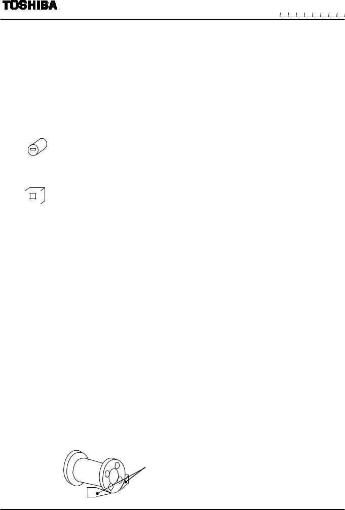
This manual uses the following markers to identify the integral type or separate type when it describes items specific to the integrated type or separate type. Items without this marker are common items to the integral type and separate type.
Integral type GF630/LF600F and GF630/LF610F:
Integral
Separate type detector GF632:
Separate
Toshiba GF63* electromagnetic flowmeter detectors can be used in combination with various types of electromagnetic flowmeter converters (LF600F, LF610F, LF602F and LF612F).
For the notes on usage, connecting, wiring, installation, configuration and maintenance of the combined converter, check the model number of the combined converter and read the instruction manual of the relevant converter.
About Safety Precautions
Read the Safety Precautions described at the front carefully and understand the contents before using this product.
The “Safely symbols” used in the “Safety Precautions” are shown in a location such as in the margin to the left of the corresponding commentary in the main text.
NOTES
1.The reproduction of the contents of this Manual in any form, whether wholly or in part, is not permitted without explicit prior consent and approval.
2.The information contained in this Manual is subject to change or review without prior notice.
3.Be sure to follow all safety, operating and handling precautions described in this Manual and the regulations in force in the country in which this product is to be used.
4.For the detail of the converter, Please refer to the converter LF600F, LF610F instruction manual.
8th Edition |
August, 2008 |
SAFETY PRECAUTIONS
Safety signs and labels affixed to the product and/or described in this manual give important information for using the product safely. They help prevent damage to property and obviate hazards for persons using the product. Make yourself familiar with signal words and symbols used for safety signs and labels. Then read the safety precautions that follow to prevent an accident involving personal injury, death or damage to property.
Explanation of signal words
The signal word or words are used to designate a degree or level of hazard seriousness.
The signal words used for the product described in this manual are WARNING and CAUTION.
Indicates a potentially hazardous situation which,
if not avoided, could result in death or serious
WARNING injury.
CAUTION |
Indicates a potentially hazardous situation which, |
if not avoided, may result in minor to moderate |
|
|
injuries or in property damage. |
Safety symbols
The following symbols are used in safety signs and labels affixed to a product and/or in the manual for giving safety instructions.
Indicates an action that is prohibited. Simply DON’T do this action.
The prohibited action is indicated by a picture or text inside or next to the circle
Indicates an action that is mandatory. DO this action.
The mandatory action is indicated by a picture or text inside or next to the circle (white letters on a colored background).
Indicates a potential hazard. The potentially hazardous situation is indicated by a picture or text inside or next to the triangle.
SAFETY PRECAUTIONS
Safety Precautions for Installation and Wiring
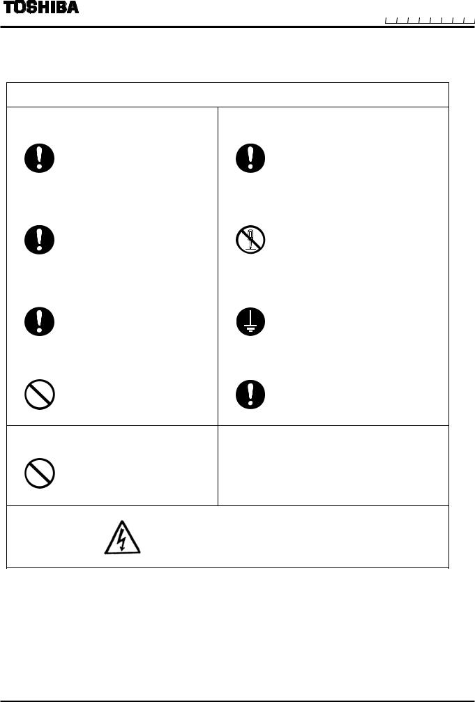
 WARNING
Do not disconnect while circuit is live unless location is known to be nonhazardous.
Live part of electric circuit or a high temperature department can cause explosion.
DON’T
Do not modify or disassemble the enclosure.
Strength degradation and defects of enclosure can cause explosion.
DON’T
Do not use parts of other products.
Protective performance degradation for hazardous location can cause explosion.
DON’T
Do not touch live circuits until assembly of all components is not over.
Protective performance degradation for hazardous location can cause explosion.
DON’T
Install per the National Electrical Code for the US (NEC, ANSI/NFPA 70) and the Canadian Electrical code for Canada (CEC, CAN/CSA-C22.1) and the drawing Appendix 1.
Unsuitable conduit connections for hazardous location can cause explosion.
DO
SAFETY PRECAUTIONS(continued)
Safety Precautions for Installation and Wiring
 CAUTION
Install a switch and fuse to isolate the |
Use an appropriate device to carry and install |
||
GF630/LF600F, GF630/LF610F and GF632 |
the GF630/LF600F, GF630/LF610F and GF632. |
||
from mains power. |
|
|
|
|
Power supply from mains power |
|
If this product falls to the ground, |
|
can cause electric shock or |
|
injury, or malfunction of or damage |
DO |
circuit break-down. |
DO |
to the product, can be caused. |
|
|
||
Turn off mains power before conducting |
Do not modify or disassemble the |
||
wiring work. |
GF630/LF600F, GF630/LF610F and GF632 |
||
|
|
unnecessarily. |
|
|
Wiring while power is applied |
|
Modifying or disassembling this |
|
can cause electric shock. |
|
product can cause |
DO |
|
DON’T |
electric shock, malfunction of or |
|
damage to this product. |
||
Turn off mains power before working on |
Ground the GF630/LF600F, GF630/LF610F and |
||
pipes. |
|
GF632 independently from power equipment. |
|
|
|
(100 ohm or less ground resistance) |
|
|
Working on pipes while power |
|
Operating this product |
|
is applied can cause |
|
without grounding can cause |
DO |
electric shock. |
DO |
electric shock or malfunction. |
|
|
||
Do not conduct wiring work with bare |
Use crimped terminal lugs for the terminal |
||
hands. |
|
board and GND terminal. |
|
|
Remaining electric charge |
|
Loose connections can cause |
|
even if power is turned off can |
|
electric shock, fire from |
DON’T |
still cause electric shock. |
DO |
excessive current or system |
|
malfunction. |
||
Do not work on piping and wiring with wet hands.
Wet hands may result in electric shock.
DON’T
The label shown left is placed near the terminal board for power supply on the converter.
(A black border and symbol on yellow triangle) Be alert to electric shock.
SAFETY PRECAUTIONS (continued)
Safety Precautions for Maintenance and Inspection
 CAUTION
Do not conduct wiring work with wet hands. |
Do not conduct wiring work when power is |
||
|
|
applied. |
|
|
Wet hands may result in |
|
Wiring while power is applied can |
|
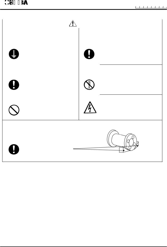
electric shock. |
|
cause electric shock. |
DON’T |
|
DON’T |
|
Do not touch the GF630/LF600F, |
|
The label shown left is placed near |
|
GF630/LF610F and GF632 main body when |
|
the terminal board for power input |
|
high temperature fluid is being measured. |
|
of the converter. (A black border |
|
|
The fluid raises the main body |
|
and symbol on yellow triangle) |
|
temperature and can cause burns |
|
Be alert to electric shock. |
DON’T |
when touched. |
|
|
|
|
|
|
Usage limitation
This product is not manufactured for applying to a system requiring safety directly involved human life as follows. Please contact your nearest Toshiba reprehensive if there is a possibility of using this product for such use.
-Main control systems of nuclear power plants, safety protection systems in nuclear facilities or other important systems requiring safety
-Medical control systems relating to life support
Warranty and Limitation of Liability
Toshiba does not accept liability for any damage or loss, material or personal, caused as a direct or indirect result of the operation of this product in connection with, or due to, the occurrence of any event of force majeure (including fire or earthquake) or the misuse of this product, whether
intentional or accidental.

Handling Precautions
To obtain the optimum performance from the GF630/LF600F, GF630/LF610F and GF632 for years of continuous operation, observe the following precautions.
(1) Do not store or install the flowmeter in:Where there is direct sunlight.
Where there is snow and ice
Infrared switches may not function correctly.
Where excessive vibration or mechanical shock occurs.Where high temperature or high humidity conditions obtain.Where corrosive atmospheres exist.
That can be submerged under water.
Where there is a sloped floor. To put the flowmeter temporarily on the floor, place it carefully with something, such as a block, to support it so that the flowmeter will not topple over.
Places where there is following factors.
Factors to impede infrared switch to operate properly
Intense light such as direct sunlight and reflected sunlight by window glass or metal platePlace where brightness changes suddenly such as ON/OFF of lighting
Dense smoke or steam near the control panel
Those attached on the control panel such as rain (dew drop), snow, ice, mud and oil, and haze due to their attachment
Light reflecting object near the control panel, or reflecting object such as metal plate placed opposing to the control panel
When any of above factors is considered, take a measure for the proper operation of infrared switch such as to place a cover or to secure a space for at least a person to stand in front of the control panel.
When unable to avoid above factors, operate the EMF converter removing the factor by covering the control panel by hand so that light does not shine on it, by cleaning those attached on the control panel, or by standing in-between the reflecting object and the control panel to block the light.
(2)In the case that the piping is grounding rings(option) to each piping.
non-conductive material, make sure to install the flange of detector using the M3 or M4 screw before
(3) Wire cables correctly and securely.
Be sure to ground at the converter side (grounding resistance 100 ohm or less).
Avoid a common ground used with other equipment where earth current may flow. An independent ground is preferable
(4)Select cable paths away from electrical equipment (motors, transformers, or radio transmitters), which causes electromagnetic or electrostatic interference.
(5)The apparatus does not be provided with the cable connections.
Please prepare yourself for the cable connections which could be used in Division2 hazardous locations.
The cable lead-in section must be tightened securely to keep air tightness.

Handling Precautions (continued)
(6)If the inside of the converter and detector's terminal box are wetted or humidified, it may cause insulation deterioration, which can result in fault or noise occurrence. So do not conduct wiring in the open air on rainy days.
Also, be careful not to wet down the converter and detector's terminal box even in the case of indoor wiring, and complete wiring work in a short period of time.
(7)Make sure the fluid to be measured will not freeze in the detector pipe. This can cause damage to the detector pipe.
(8)Select appropriate wetted materials suited for the process fluid to be measured. Otherwise, fluid leakage due to corrosion can be caused.
(9)Observe the following precautions when you open the converter housing cover:
•Do not open the cover in the open air unprotected against rain or wind. This can cause electric shock or cause damage to the flowmeter electronics.
Do not open the cover under high ambient temperature or high humidity
conditions or in corrosive atmospheres. This can cause deterioration of system accuracy or cause damage to the flowmeter electronics.
(10)Since a varistor is built in converter, do not conduct a withstand voltage test for the converter.
In addition, the voltage for checking the insulation of the converter must be 250VDC or lower.
(11)This product may cause interference to radio and television sets if they are used near the installation site. Use metal conduits etc. for cables to prevent this interference.
(12)Radio transmitters such as transceivers or cellular phones may cause interference to the flowmeter if they are used near the installation site. Observe the following precautions when using them:
•Close a transmitter cover before using a transceiver.
•Do not use a transceiver whose output power is more than 5 W.
•Move the antenna of a transceiver or a cellular phone at least 50 cm away from the flowmeter and signal cables when using it.
•Do not use a radio transmitter or a cellular phone near the flowmeter while it is operating online. The transmitter or cellular phone’s output impulse noise may interfere with the flowmeter.
•Do not install a radio transmitter antenna near the flowmeter and signal cables.
(13)For reasons of flowmeter failure, inappropriate parameters, unsuitable cable connections or poor installation conditions, the flowmeter may not operate properly. To prevent any of these problems causing a system failure, it is recommended that you have preventive measures designed and installed on the flowmeter signal receiving side.
(14)For installation and connectirn of the converter, check the model number of converter and read the instruction manual of the relevant converter.
*We assume no responsibility for nonconformity caused by violation of precautions described in this manual or used in violation of the installation method and the operation method stipulated in a relevant ordinance or other regulations.
About disposal
When you dispose of this electromagnetic flowmeter detector, follow the ordinance or regulations of your state.

Table of Contents
SAFETY PRECAUTIONS ····················································································· 2 Handling Precautions ······························································································ 6
1.Product Inspection and Storage ······································································ 9 1.1 Product Inspection ······················································································· 9
1.2 Storage ········································································································ 9
2.Overview ·········································································································· 10
3.Names of Parts ································································································· 11
4.Installation ······································································································· 14
4.1 |
Notes on Selecting the Installation Location ············································· 16 |
4.2 |
Mounting Procedure···················································································· 16 |
4.3 |
Piping Connections ··················································································· 22 |
4.4 |
Grounding ································································································· 25 |
5.Wiring ·············································································································· 27
5.1Cables ········································································································ 29
5.2External Device Connections and Grounding ············································ 30
5.3 |
Notes on Wiring ······················································································ 30 |
5.4 |
Wiring ····································································································· 31 |
6.Operation ········································································································· 34
7. Maintenance and Troubleshooting ································································· 35
7.1 |
Maintenance ······························································································ 36 |
7.2 |
Troubleshooting ························································································ 37 |
8.Principle of Operation ··················································································· 40
9.Specifications ·································································································· 41
9.1 |
Flowmeter Specifications |
··········································································· 41 |
9.2 |
Type Specification Code |
············································································ 46 |
10. Outline Dimensions ························································································· 47
Appendix 1
1-1 A system diagram for GF630/LF600F and GF630/LF610F ···························· 52 1-2 A system diagram for GF632·········································································· 53
1. Product Inspection and Storage
1.1 Product Inspection
GF630 series electromagnetic flowmeter is shipped in a cardboard container filled with shock-absorbing materials. Open the package carefully and check as follows:
Make sure the following items are included in the package.
For the integral type (when a converter and detector are united)
|
|
|
|
|
Electromagnetic flowmeter main unit |
--------------------------------- 1 unit |
|
|
|
|
|
|
Instruction manuals |
One each for the converter and detector |
|
|
Integral |
||||||
|
Ground cable ------------------------------------------------------------- |
|
2 pieces |
||||
|
For the separate type (when a converter and detector are separated) |
||||||
|
|
|
|
|
Electromagnetic flowmeter converter---------------------------------- |
1 unit |
|
|
|
|
|
|
|||
|
|
|
|
|
-----------------------------------Electromagnetic flowmeter detector |
1 unit |
|
|
|
|
|
Instruction manuals |
|
each for the converter and detector |
|
Separate |
|
||||||
|
|
|
|
|
Ground cable ------------------------------------------------------------- |
|
2 pieces |
Inspect the flowmeter for indications of damage that may have occurred during shipment.
Make sure the type and specifications of the flowmeter are in accordance with the ordered specifications.
If you cannot find the items listed above or any problem exists, contact your nearest Toshiba representative.
1.2 Strage
To store the electromagnetic flowmeter after opening the package, select a storing place as follows and keep it under the conditions described below:
 CAUTION
(1)Avoid places where there is direct sunlight, rain or wind.
(2)Store the product in a well-ventilated place. Avoid places of extremely high humidity or extremely high or low temperature. The following environment is recommended:
•Humidity range: 10 to 90% RH (no condensation)
•Storage temperature: –25 to +65° C
(3)Avoid places where vibrations or mechanical shock occur.
(4)If the cover of the converter is left open while being stored, gradual deterioration of circuit isolation can be caused. Therefore don’t open the cover until it is connected with wires.
(5)To put the flowmeter temporarily on the floor, place it carefully with something, such as block or stopper, to support it so that the flowmeter will not topple over.
flowmeter |
Stopper, etc. to prevent from toppling over it. |
2. Overview
The GF630/LF600F, GF630/LF610F and GF632 electromagnetic flowmeter can be use in the following hazardous (classified) locations.
Class , Division 2, Groups A, B, C and D,
Class , Division 2, Groups E, F and G
Class
The GF630 and GF632 electromagnetic flowmeter measures the volumetric flow rates of electrically conductive materials on the basis of Faraday's Law of electromagnetic induction.
The device consists of two units: the GF630 and GF632 detector, through which the fluid to be measured flows, and the converter, which receives the electromotive force signals from the detector, then converts the
signals into the 4–20 mA dc signal.
Features
Every type of electromagnetic flowmeter has the following features:
Fluid flow is not obstructed and pressure loss is negligible.
The process fluid's temperature, pressure, density or flow conditions has no effect on the accuracy of the flowmeter.
The flowmeter output is directly proportional to the process flow rate, thus it is easy to read its output.

3. Names of Parts
3.1 Appearance
3.1.1 Appearance of GF630/LF600F and GF630/LF610F
Integral
|
for Power cable |
|
1/2-14NPT |
Terminal block cover |
for I/Ol cable |
1/2-14NPT |
Ground terminal for converter
Ground terminal for detector
For the detail of the converter, check the converter LF600F and LF610F instruction manual.
|
|
Hanging hook |
Converter LF600F and LF610F |
*Provided for upper 8 inch |
|
(200mm to 600mm) |
||
|
|
|
|
|
|
Flow direction arrow
GF630 Detector
Flange 
Ground cable*
Grounding ring
( Provided for PTFE lining only )
Figure 3.1.1 Appearance of GF630/LF600F and GF630/LF610F
Note: The ground cables are included in the package, so install them to flanges as shown in the Fig.4.5 as needed. (The screws are equipped to detector flanges.)
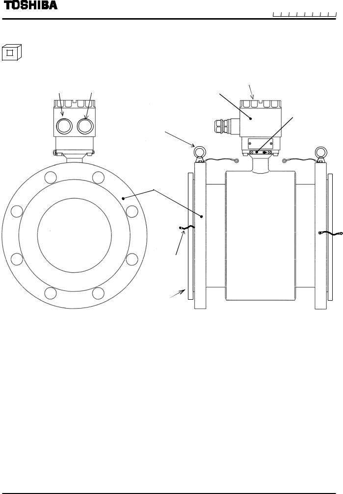
3.1.2 Appearance of Detector GF632
Separate
for Excitation cable 1/2 – 14 NPT
Ground terminal for detector 
for Signal cable |
|
|
|
Terminal Box Cover |
||||||
1/2 – 14 NPT |
Terminal Box |
|||||||||
|
||||||||||
Hanging hook |
|
|
|
|
|
|
|
|
Flow direction arrow |
|
|
|
|
|
|||||||
*Provided for upper 8 inch |
|
|
|
|
|
|
|
|
|
|
(200mm to 600mm) |
|
|
|
|
|
|
|
|
|
|
|
|
|
|
|
|
|
|
|
|
|
|
|
|
|
|
|
|
|
|
|
|
|
|
|
|
|
|
|
|
|
|
|
|
|
|
|
|
|
|
|
|
|
|
|
|
|
|
|
|
|
|
|
|
|
|
|
|
|
|
|
|
|
|
|
|
Flange
Ground cable*
Grounding ring
( Provided for PTFE lining only )
Figure 3.1.2 Appearance of Detector GF632
Note: The ground cables are included in the package, so install them to flanges as shown in the Fig.4.5 as needed. (The screws are equipped to detector flanges.)
3.2 Construction of the terminal blocks
3.2.1 Terminal Block Construction of GF630/LF600F and GF630/LF610F Type
For the detail of the converter, check the converter LF600F and LF610F instruction manual.
Integral
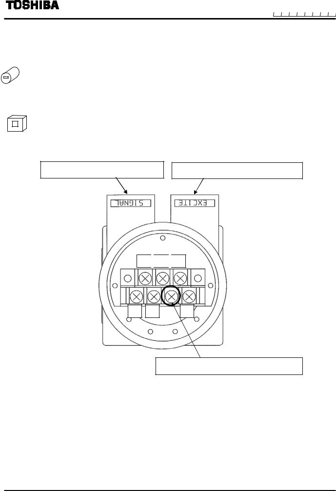
3.2.2 Terminal Block Construction of GF632 Type
Separate
To signal cable terminal (A,B and G)
To excitation cable terminal(X,Y and E)
B 
 E
E 
 Y
Y
A |
G |
X |
Don’t connect wiring to this terminal.
Figure 3.2.2 Terminal Block of GF632
4. Installation
Safety Precautions for Installation
 WARNING
Do not active live circuits under environment of explosive atmospheres.
Live part of electric circuit or a high temperature department can cause explosion.
DON’T
Do not use parts of other products.
Protective performance degradation for hazardous location can cause explosion.
DON’T
Do not active live circuits While assembly of all components is not over.
Protective performance degradation for hazardous location can cause explosion.
DON’T
Install per the National Electrical Code for the US (NEC, ANSI/NFPA 70) and the Canadian Electrical code for Canada (CEC, CAN/CSA-C22.1) and the drawing Appendix 1.
Unsuitable conduit connections for hazardous location can cause explosion.
DO
|
|
|
|
|
|
|
|
|
|
|
|
|
|
|
|
|
|
|
|
|
|
|
|
|
|
|
|
|
|
|
|
|
|
|
|
|
|
|
|
|
|
|
|
|
|
||
|
|
|
|
|
|
|
|
|
|
|
|
|
|
|
|
|
|
|
|
|
|
||
|
|
|
|
|
|
|
|
|
|
|
|
|
|
|
|
|
|
|
|
|
|
|
|
|
|
|
|
|
|
|
|
|
|
|
|
|
|
|
|
|
|
|
|
|
CAUTION |
||
|
|
Ground the GF630/LF600F, |
Use an appropriate device to carry and install |
||||||||||||||||||||
|
|
|
|
|
|
|
GF630/LF610F and GF632 independently |
the GF630/LF600F, GF630/LF610F and GF632 . |
|||||||||||||||
|
|
|
|
|
|
|
from power equipment. (100 ohm or less |
|
|
|
|||||||||||||
|
|
|
|
|
|
|
ground resistance) |
|
If his product falls to the ground, |
||||||||||||||
|
|
|
|
|
|
|
|
|
|
|
|
|
|
|
|
|
|
|
|
Operating this product without |
|
||
|
|
|
|
|
|
|
|
|
|
|
|
|
|
|
|
|
|
|
|
|
injury, or malfunction of or damage to |
||
|
|
|
|
|
|
|
|
|
|
|
|
|
|
|
|
|
|
|
|
grounding can cause electric |
|
||
|
|
|
|
|
|
|
|
|
|
|
|
|
|
|
|
|
|
|
|
|
the product, can be caused. |
||
|
|
|
|
|
|
|
|
DO |
|
|
|
|
|
shock or malfunction. |
DO |
||||||||
|
|
|
|
|
|
|
|
|
|
|
|
|
|
|
|||||||||
|
|
|
|
|
|||||||||||||||||||
|
|
Install a switch and fuse to isolate the |
Do not modify or disassemble the |
||||||||||||||||||||
|
|
|
|
|
|
|
GF630/LF600F, GF630/LF610F and GF632 |
GF630/LF600F, GF630/LF610F and GF632 |
|||||||||||||||
|
|
|
|
|
|
|
from mains power. |
||||||||||||||||
|
|
|
|
|
|
|
unnecessarily. |
||||||||||||||||
|
|
|
|
|
|
|
|
|
|
|
|
|
|
|
|
|
|
|
|
Power supply from mains power |
|||
|
|
|
|
|
|
|
|
|
|
|
|
|
|
|
|
|
|
|
|
|
Modifying or disassembling this product |
||
|
|
|
|
|
|
|
|
|
|
|
|
|
|
|
|
|
|
|
|
can cause electric shock or |
|
can cause electric shock, malfunction |
|
|
|
|
|
|
|
|
|
DO |
|
|
|
|
|
circuit break-down. |
DON’T |
or damage to this product. |
|||||||
|
|
|
|
|
|
|
|
|
|
|
|
|
|
|
|
||||||||
|
|
Do not work on piping and wiring with wet |
|
The label shown left is placed near the |
|||||||||||||||||||
|
|
|
|
|
hands. |
|
|
|
|
|
|
|
|||||||||||
|
|
|
|
|
|
|
|
|
|
|
|
terminal board for power supply to the |
|||||||||||
|
|
|
|
|
|
|
|
|
|
|
|
|
|
|
|
|
|
|
|
Wet hands may result in electric |
|
||
|
|
|
|
|
|
|
|
|
|
|
|
|
|
|
|
|
|
|
|
|
converter. |
||
|
|
|
|
|
|
|
|
|
|
|
|
|
|
|
|
|
|
|
|
shock |
|
||
|
|
|
|
|
|
|
|
|
|
|
|
|
|
|
|
|
|
|
|
|
Be alert to electric shock |
||
|
|
|
|
|
|
|
|
|
|
|
|
|
|
|
|
|
|
|
|
|
|
||
DON’T
To put the flowmeter temporarily on the floor, place it carefully with something, such as stopper, to support it so that GF630/LF600F, GF630/LF610F and GF632
will not topple over. |
flowmeter |
Stopper, etc. to prevent
from toppling over it.
DO
4.1Notes on Selecting the Installation Location
1.Avoid places within the immediate proximity of equipment producing electrical interference (such as motors, transformers, radio transmitters, electrolytic cells, or other equipment causing electromagnetic or electrostatic interference).
2.Avoid places where excessive pipe vibration occurs.
3.Avoid places where fluid is pumped in a pulsating manner
4.Avoid places where there is direct sunlight. If this is unavoidable, use an appropriate shade
5.Avoid places where corrosive atmospheres or high humidity conditions obtain.
6.Avoid places where there may be limited access such as pipes installed next to high ceilings or constricted areas where clearance for installation or maintenance work is not provided.
7.Design piping so that the detector pipe is always filled with fluid, whether the fluid is flowing or not.
8.The detector has no adjustable piping mechanism. Install an adjustable short pipe where needed.
9.Chemical injections should be conducted on the downstream side of the flowmeter.
10. The maximum length of the cable that connects the detector and converter is 300m. Select the
converter installation location so that the distance between the detector and converter dose not exceed
Separate 300m.
4.2 Mounting Procedure
4.2.1 Pipe checks
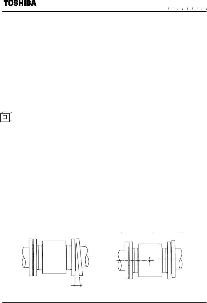
(1) Before installing pipes, check for any leaning, misplacement or eccentricity as illustrated in Figure 4.1. An attempt to unreasonably connect pipes that are inclined may lead to a detector breakdown or fluid leakage. Connecting pipes in an eccentric state may also cause wears and tear of linings and grounding rings, as well as measurement errors.
Before installing pipes, make sure to flush the interior of the pipes to remove deposited material.
(a) Pipe leaning |
(b) Pipe axis misplacement (or eccentricity) |
Eccentricity
Inclination
Figure 4.1 Pipe leaning and axis misplacement
 Loading...